EP0629010A2 - Cover for a lead-acid battery - Google Patents
Cover for a lead-acid battery Download PDFInfo
- Publication number
- EP0629010A2 EP0629010A2 EP94108117A EP94108117A EP0629010A2 EP 0629010 A2 EP0629010 A2 EP 0629010A2 EP 94108117 A EP94108117 A EP 94108117A EP 94108117 A EP94108117 A EP 94108117A EP 0629010 A2 EP0629010 A2 EP 0629010A2
- Authority
- EP
- European Patent Office
- Prior art keywords
- cover
- battery
- header
- pipes
- electrolyte
- Prior art date
- Legal status (The legal status is an assumption and is not a legal conclusion. Google has not performed a legal analysis and makes no representation as to the accuracy of the status listed.)
- Ceased
Links
Images


Classifications
-
- H—ELECTRICITY
- H01—ELECTRIC ELEMENTS
- H01M—PROCESSES OR MEANS, e.g. BATTERIES, FOR THE DIRECT CONVERSION OF CHEMICAL ENERGY INTO ELECTRICAL ENERGY
- H01M4/00—Electrodes
- H01M4/02—Electrodes composed of, or comprising, active material
- H01M4/14—Electrodes for lead-acid accumulators
- H01M4/16—Processes of manufacture
- H01M4/22—Forming of electrodes
-
- H—ELECTRICITY
- H01—ELECTRIC ELEMENTS
- H01M—PROCESSES OR MEANS, e.g. BATTERIES, FOR THE DIRECT CONVERSION OF CHEMICAL ENERGY INTO ELECTRICAL ENERGY
- H01M50/00—Constructional details or processes of manufacture of the non-active parts of electrochemical cells other than fuel cells, e.g. hybrid cells
- H01M50/10—Primary casings, jackets or wrappings of a single cell or a single battery
- H01M50/147—Lids or covers
-
- H—ELECTRICITY
- H01—ELECTRIC ELEMENTS
- H01M—PROCESSES OR MEANS, e.g. BATTERIES, FOR THE DIRECT CONVERSION OF CHEMICAL ENERGY INTO ELECTRICAL ENERGY
- H01M50/00—Constructional details or processes of manufacture of the non-active parts of electrochemical cells other than fuel cells, e.g. hybrid cells
- H01M50/30—Arrangements for facilitating escape of gases
- H01M50/35—Gas exhaust passages comprising elongated, tortuous or labyrinth-shaped exhaust passages
-
- H—ELECTRICITY
- H01—ELECTRIC ELEMENTS
- H01M—PROCESSES OR MEANS, e.g. BATTERIES, FOR THE DIRECT CONVERSION OF CHEMICAL ENERGY INTO ELECTRICAL ENERGY
- H01M50/00—Constructional details or processes of manufacture of the non-active parts of electrochemical cells other than fuel cells, e.g. hybrid cells
- H01M50/70—Arrangements for stirring or circulating the electrolyte
- H01M50/77—Arrangements for stirring or circulating the electrolyte with external circulating path
-
- Y—GENERAL TAGGING OF NEW TECHNOLOGICAL DEVELOPMENTS; GENERAL TAGGING OF CROSS-SECTIONAL TECHNOLOGIES SPANNING OVER SEVERAL SECTIONS OF THE IPC; TECHNICAL SUBJECTS COVERED BY FORMER USPC CROSS-REFERENCE ART COLLECTIONS [XRACs] AND DIGESTS
- Y02—TECHNOLOGIES OR APPLICATIONS FOR MITIGATION OR ADAPTATION AGAINST CLIMATE CHANGE
- Y02E—REDUCTION OF GREENHOUSE GAS [GHG] EMISSIONS, RELATED TO ENERGY GENERATION, TRANSMISSION OR DISTRIBUTION
- Y02E60/00—Enabling technologies; Technologies with a potential or indirect contribution to GHG emissions mitigation
- Y02E60/10—Energy storage using batteries
Definitions
- the subject of the present invention is a cover for a lead-acid starter battery, which, in known manner, comprises a rigid container substantially in the form of a tank and divided by baffles into a plurality of cells in each of which a plurality of electrode plates are accommodated immersed in an electrolyte and intended to be subjected to an electrochemical process for forming the active material, in which the battery is coupled to a system for recirculating and cooling the electrolyte present in the container.
- the cover according to the invention is characterised in that, in its wall, it has a first and a second header pipe from which respective pluralities of branch pipes emerge, protruding from the face of the cover intended to face the interior of the battery container, in respective positions such that, when the cover is coupled to the container, at least one branch pipe from the first header pipe and at least one branch pipe from the second header pipe face each cell of the battery; these header pipes are accessible through corresponding respective apertures disposed in an outer surface of the cover.
- the cover is made in a single part of moulded plastics material.
- the access apertures in the header pipes are adjacent one another and associated therewith is a single removable closing element having a passage in which a filtering element of porous material is disposed.
- the header pipes can advantageously contain elements which can define a labyrinth path for the gases which are evolved when the electrolyte is in use and can restrain any particles of electrolyte carried by these gases.
- the coupling of a battery provided with a cover according to the invention to a system for recirculating and cooling the electrolyte when the electrochemical process for forming the active material is being performed is extremely simple: the first header pipe is used as a pipe for drawing in the electrolyte from the battery cell whilst the second header pipe is used for conveying the treated electrolyte back to the cells.
- the access apertures in the above header pipes are closed again and these pipes advantageously act as breather pipes for the gases evolved when the electrolyte is in use.
- the cover according to the invention has a small number of apertures giving access to the cells and a correspondingly small number of plugs. This can be brought about by means of a single moulding operation, resulting in a simple structure which is cheap to produce.
- a cover for a battery according to the invention is generally indicated 1.
- This cover is advantageously produced by moulding a plastics material.
- the cover 1 is generally rectangular and has on its periphery an edge or flange 2 to be coupled and heat-sealed to the upper edge of a battery container, not shown.
- the cover 1 has a raised part 3 which is generally T-shaped in plan view. Adjacent this raised part of the cover, two tubular elements 4, defining passages or seats for the extension of a respective pole of the battery, extend from the lower part of the cover. As Figure 2 shows, each tubular element 4 is inserted in a corresponding aperture 5 in the cover.
- An integral formation extends from the lower face of the raised part 3 of the cover.
- This formation contains two header pipes 7 and 8 which are adjacent one another and extend parallel to the raised wall 3 of the cover.
- the header pipes 7 and 8 have respective ends 7a and 8a which are blind.
- the other ends 7b and 8b of these header pipes communicate with respective apertures 9 and 10 which lead into a common embedded seat 11 produced in a side wall 12 which connects the raised wall 3 to the edge or flange 2 of the cover (see also Figures 1 and 5).
- Respective pluralities of branch pipes 13 and 14 respectively emerge from the lower walls of the header pipes 7 and 8.
- the branch pipes 13 and 14 extend at right-angles to the axes of the associated header pipes 7 and 8.
- the branch pipes 13 preferably have an extension which is greater than the branch pipes 14, as shown in the drawings.
- a closure element or plug 15 ( Figures 1, 6 and 7) of complementary shape is associated with the seat 11 of the cover.
- the face of this plug which is to face the header pipes 7 and 8 has a recess indicated 16 in Figures 6 and 7.
- the plug 15 has a central aperture 17 in which a pad 18 of porous material is disposed.
- the header pipes 7 and 8 enable an electrochemical process for forming the active material of the plates to be performed easily.
- these header pipes are connected to an external system for recirculating, cooling and controlling the density of the electrolyte, external to the battery, by two tubes (not illustrated).
- the pipe 7 acts as a collector for drawing in the electrolyte to the processing system, whilst the pipe 8 acts a collector for conveying the treated electrolyte back to the battery cells.
- the length of the branch pipes 13 of the intake collector 7 is such that, at the end of the formation process, the level of the electrolyte in the battery reaches the lower end of the pipe. After the formation, the level of the electrolyte in the battery progressively drops, following its degassification, by a substantially predetermined measure, generally of the order of a few millimetres.
- the length of the branch pipes 13 thus indirectly determines the definitive level of the electrolyte in a battery.
- the seat 11 of the cover is closed with the plug 15 and, when the battery is subsequently used, the header pipes 7 and 8 advantageously act as breather pipe manifolds for the gases evolved from the electrolyte. These gases are vented to the exterior of the battery through the porous pad 18 carried by the plug 15.
- respective shaped elements capable of defining a labyrinth path for these gases, can be disposed in the header pipes 7 and 8.
- shaped element 20 substantially has a rod 21 from which transverse walls 22 extend which are at an axial spacing along the rod and offset transversely and at an angle, so as to define respective labyrinth paths for the gases inside the associated header pipes 7 and 8. Any particles of electrolyte conveyed by these gases condense on the walls 22.
- the access apertures in the header pipes can be produced at a spacing from one another and provided with respective closure elements which can vent the gases evolved from the electrolyte.
- the closure element or elements of the apertures can comprise a pad of porous material, as described above, or can consist of conventional plugs provided with breather pipes.
Abstract
Description
- The subject of the present invention is a cover for a lead-acid starter battery, which, in known manner, comprises a rigid container substantially in the form of a tank and divided by baffles into a plurality of cells in each of which a plurality of electrode plates are accommodated immersed in an electrolyte and intended to be subjected to an electrochemical process for forming the active material, in which the battery is coupled to a system for recirculating and cooling the electrolyte present in the container.
- The cover according to the invention is characterised in that, in its wall, it has a first and a second header pipe from which respective pluralities of branch pipes emerge, protruding from the face of the cover intended to face the interior of the battery container, in respective positions such that, when the cover is coupled to the container, at least one branch pipe from the first header pipe and at least one branch pipe from the second header pipe face each cell of the battery; these header pipes are accessible through corresponding respective apertures disposed in an outer surface of the cover.
- Advantageously, the cover is made in a single part of moulded plastics material.
- Preferably, the access apertures in the header pipes are adjacent one another and associated therewith is a single removable closing element having a passage in which a filtering element of porous material is disposed.
- The header pipes can advantageously contain elements which can define a labyrinth path for the gases which are evolved when the electrolyte is in use and can restrain any particles of electrolyte carried by these gases.
- The coupling of a battery provided with a cover according to the invention to a system for recirculating and cooling the electrolyte when the electrochemical process for forming the active material is being performed is extremely simple: the first header pipe is used as a pipe for drawing in the electrolyte from the battery cell whilst the second header pipe is used for conveying the treated electrolyte back to the cells.
- Following the electrochemical formation of the active material, the access apertures in the above header pipes are closed again and these pipes advantageously act as breather pipes for the gases evolved when the electrolyte is in use.
- The cover according to the invention has a small number of apertures giving access to the cells and a correspondingly small number of plugs. This can be brought about by means of a single moulding operation, resulting in a simple structure which is cheap to produce.
- Further characteristics and advantages of the cover according to the invention will appear from the following detailed description, provided purely by way of non-limiting example, with reference to the appended drawings, in which:
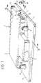
- Figure 1 is a perspective view of a cover according to the invention;
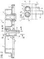
- Figure 2 is a sectional view according to the line II-II in Figure 1;
- Figures 3 and 4 are sectional views along the lines III-III and IV-IV respectively of Figure 2;
- Figure 5 is a front view on enlarged scale of a detail shown by the arrow V in Figure 1;
- Figure 6 is a front view according to the arrow VI of Figure 1, of a closure plug associated with the cover;
- Figure 7 is a sectional view according to the line VII-VII of Figure 6; and
- Figure 8 is a perspective view showing an embodiment of an element shaped so as to define a labyrinth path in the header pipes of the cover according to the invention.
- In Figures 1 to 5, a cover for a battery according to the invention is generally indicated 1. This cover is advantageously produced by moulding a plastics material.
- In the embodiment illustrated by way of example, the cover 1 is generally rectangular and has on its periphery an edge or
flange 2 to be coupled and heat-sealed to the upper edge of a battery container, not shown. - As can be seen in particular in Figure 1, in the embodiment illustrated, the cover 1 has a raised part 3 which is generally T-shaped in plan view. Adjacent this raised part of the cover, two
tubular elements 4, defining passages or seats for the extension of a respective pole of the battery, extend from the lower part of the cover. As Figure 2 shows, eachtubular element 4 is inserted in acorresponding aperture 5 in the cover. - An integral formation, generally indicated 6 in Figure 2, extends from the lower face of the raised part 3 of the cover. This formation contains two
header pipes 7 and 8 which are adjacent one another and extend parallel to the raised wall 3 of the cover. As is shown in Figures 3 and 4, theheader pipes 7 and 8 haverespective ends other ends respective apertures 9 and 10 which lead into a common embeddedseat 11 produced in aside wall 12 which connects the raised wall 3 to the edge orflange 2 of the cover (see also Figures 1 and 5). - Respective pluralities of
branch pipes header pipes 7 and 8. In the embodiment illustrated, thebranch pipes header pipes 7 and 8. - The
branch pipes 13 preferably have an extension which is greater than thebranch pipes 14, as shown in the drawings. - A closure element or plug 15 (Figures 1, 6 and 7) of complementary shape is associated with the
seat 11 of the cover. The face of this plug which is to face theheader pipes 7 and 8 has a recess indicated 16 in Figures 6 and 7. - The
plug 15 has acentral aperture 17 in which apad 18 of porous material is disposed. - In a battery provided with a cover of the type described above, the
header pipes 7 and 8 enable an electrochemical process for forming the active material of the plates to be performed easily. For this purpose, these header pipes are connected to an external system for recirculating, cooling and controlling the density of the electrolyte, external to the battery, by two tubes (not illustrated). During this operation, the pipe 7 acts as a collector for drawing in the electrolyte to the processing system, whilst thepipe 8 acts a collector for conveying the treated electrolyte back to the battery cells. - The length of the
branch pipes 13 of the intake collector 7 is such that, at the end of the formation process, the level of the electrolyte in the battery reaches the lower end of the pipe. After the formation, the level of the electrolyte in the battery progressively drops, following its degassification, by a substantially predetermined measure, generally of the order of a few millimetres. The length of thebranch pipes 13 thus indirectly determines the definitive level of the electrolyte in a battery. - When the electrochemical formation of the active material associated with the battery electrodes has been completed, the
seat 11 of the cover is closed with theplug 15 and, when the battery is subsequently used, theheader pipes 7 and 8 advantageously act as breather pipe manifolds for the gases evolved from the electrolyte. These gases are vented to the exterior of the battery through theporous pad 18 carried by theplug 15. - Advantageously, in order to restrain any particles of electrolyte which these gases may entrain, respective shaped elements, capable of defining a labyrinth path for these gases, can be disposed in the
header pipes 7 and 8. One embodiment of such an element is shown in Figure 8. In the embodiment illustrated in this drawing, theshaped element 20 substantially has arod 21 from whichtransverse walls 22 extend which are at an axial spacing along the rod and offset transversely and at an angle, so as to define respective labyrinth paths for the gases inside the associatedheader pipes 7 and 8. Any particles of electrolyte conveyed by these gases condense on thewalls 22. - Naturally, the principle of the invention remaining the same, the forms of embodiment and details of production can be widely varied with respect to what has been described and illustrated purely by way of non-limiting example, without departing from the scope of the present invention.
- Thus, for example, the access apertures in the header pipes can be produced at a spacing from one another and provided with respective closure elements which can vent the gases evolved from the electrolyte.
- The closure element or elements of the apertures can comprise a pad of porous material, as described above, or can consist of conventional plugs provided with breather pipes.
Claims (8)
- A cover for a lead-acid starter battery which comprises in known manner a rigid container, substantially in the form of a tank, divided by baffles into a plurality of cells, in each of which is accommodated a plurality of electrode plates immersed in an electrolyte and intended to be subjected to an electrochemical formation process in which the battery is coupled to a system for recirculating and cooling the electrolyte present in the container; the cover (1) being characterised in that, in its wall (3), it has a first and a second header pipe (7, 8) from which respective pluralities of branch pipes (13, 14) protruding from the cover face (1) which is intended to face the interior of the battery container emerge, in respective positions such that, when the cover (1) is coupled to the container, at least one branch pipe from the first header pipe and at least one branch pipe from the second header pipe face each cell of the battery; the header pipes (7, 8) being accessible through corresponding respective apertures (9, 10) disposed in an outer surface of the cover (1).
- A cover according to Claim 1, characterised in that the branch pipes (13) extending from the first header pipe (7) have an extension which is greater than that of the branch pipes (14) extending from the second header pipe (8).
- A cover according to Claim 1 or 2, characterised in that it is produced in a single part of moulded plastics material.
- A cover according to any one of the preceding claims, characterised in that the apertures (9, 10) in the header pipes (7, 8) are adjacent one another.
- A cover according to Claim 4, characterised in that a single removable closure element (15) is associated with the apertures (9, 10).
- A cover according to Claim 5, characterised in that the closure element (15) has a passage (17) in which a filtering element (18) of porous material is disposed.
- A cover according to any one of the preceding claims, characterized in that the apertures (9, 10) of the header pipes (7, 8) are provided in a side surface (12) of the cover (1) such that the apertures (9, 10) are accessible on one side of the battery when the cover (1) is coupled to the container.
- A cover according to any one of the preceding claims, characterised in that the header pipes (7, 8) are provided with shaped elements (20) which can define a labyrinth path for the gases evolved during use of the electrolyte and which can restrain any particles of electrolyte conveyed by these gases.
Applications Claiming Priority (2)
| Application Number | Priority Date | Filing Date | Title |
|---|---|---|---|
| ITTO930403A IT1270423B (en) | 1993-06-04 | 1993-06-04 | COVER FOR LEAD-ACID BATTERIES |
| ITTO930403 | 1993-06-04 |
Publications (2)
| Publication Number | Publication Date |
|---|---|
| EP0629010A2 true EP0629010A2 (en) | 1994-12-14 |
| EP0629010A3 EP0629010A3 (en) | 1995-03-29 |
Family
ID=11411537
Family Applications (1)
| Application Number | Title | Priority Date | Filing Date |
|---|---|---|---|
| EP94108117A Ceased EP0629010A3 (en) | 1993-06-04 | 1994-05-26 | Cover for a lead-acid battery. |
Country Status (2)
| Country | Link |
|---|---|
| EP (1) | EP0629010A3 (en) |
| IT (1) | IT1270423B (en) |
Cited By (3)
| Publication number | Priority date | Publication date | Assignee | Title |
|---|---|---|---|---|
| WO1996011505A1 (en) * | 1994-10-11 | 1996-04-18 | Olimpio Stocchiero | A lid for accumulator batteries and charging devices co-operating with said lid |
| WO2008056859A1 (en) | 2006-11-07 | 2008-05-15 | Global Battery Co., Ltd. | Battery case cover |
| WO2015092960A1 (en) * | 2013-12-16 | 2015-06-25 | パナソニックIpマネジメント株式会社 | Lead storage battery |
Citations (4)
| Publication number | Priority date | Publication date | Assignee | Title |
|---|---|---|---|---|
| US2678344A (en) * | 1951-03-31 | 1954-05-11 | Electric Storage Battery Co | Storage battery filling and venting device |
| GB1378622A (en) * | 1972-12-26 | 1974-12-27 | Japan Storage Battery Co Ltd | Electric storage battery with automatic water filling |
| US4087592A (en) * | 1977-04-19 | 1978-05-02 | Japan Storage Battery Company Limited | Wafer supply structure for liquid storage battery |
| EP0514918A1 (en) * | 1991-05-23 | 1992-11-25 | Olimpio Stocchiero | Device for exhausting the fumes forming inside accumulator batteries |
-
1993
- 1993-06-04 IT ITTO930403A patent/IT1270423B/en active IP Right Grant
-
1994
- 1994-05-26 EP EP94108117A patent/EP0629010A3/en not_active Ceased
Patent Citations (4)
| Publication number | Priority date | Publication date | Assignee | Title |
|---|---|---|---|---|
| US2678344A (en) * | 1951-03-31 | 1954-05-11 | Electric Storage Battery Co | Storage battery filling and venting device |
| GB1378622A (en) * | 1972-12-26 | 1974-12-27 | Japan Storage Battery Co Ltd | Electric storage battery with automatic water filling |
| US4087592A (en) * | 1977-04-19 | 1978-05-02 | Japan Storage Battery Company Limited | Wafer supply structure for liquid storage battery |
| EP0514918A1 (en) * | 1991-05-23 | 1992-11-25 | Olimpio Stocchiero | Device for exhausting the fumes forming inside accumulator batteries |
Cited By (7)
| Publication number | Priority date | Publication date | Assignee | Title |
|---|---|---|---|---|
| WO1996011505A1 (en) * | 1994-10-11 | 1996-04-18 | Olimpio Stocchiero | A lid for accumulator batteries and charging devices co-operating with said lid |
| US6120929A (en) * | 1994-10-11 | 2000-09-19 | Stocchiero; Olimpio | Lid for accumulator batteries and charging devices co-operating with said lid |
| WO2008056859A1 (en) | 2006-11-07 | 2008-05-15 | Global Battery Co., Ltd. | Battery case cover |
| EP2080239A1 (en) * | 2006-11-07 | 2009-07-22 | Global Battery Co., Ltd. | Battery case cover |
| EP2080239A4 (en) * | 2006-11-07 | 2010-11-17 | Global Battery Co Ltd | Battery case cover |
| WO2015092960A1 (en) * | 2013-12-16 | 2015-06-25 | パナソニックIpマネジメント株式会社 | Lead storage battery |
| JP5838382B2 (en) * | 2013-12-16 | 2016-01-06 | パナソニックIpマネジメント株式会社 | Lead acid battery |
Also Published As
| Publication number | Publication date |
|---|---|
| IT1270423B (en) | 1997-05-05 |
| ITTO930403A0 (en) | 1993-06-04 |
| EP0629010A3 (en) | 1995-03-29 |
| ITTO930403A1 (en) | 1994-12-04 |
Similar Documents
| Publication | Publication Date | Title |
|---|---|---|
| US4444853A (en) | Storage battery construction | |
| DE69925067T2 (en) | Monoblock battery with heat exchange device by passing a liquid | |
| GB1574085A (en) | Storage batteries | |
| US4215186A (en) | Battery plate separator and battery containing the same | |
| DE60109130T2 (en) | Electric accumulator battery | |
| JP2002510125A (en) | Battery case for metal thin film cells | |
| DE2906538B2 (en) | Device for degassing a rechargeable battery | |
| EP2766940B1 (en) | Case system, battery and battery rack with improved stacking | |
| EP1280214B1 (en) | A leak resistant automotive battery | |
| KR20130099991A (en) | Rechargeable battery having a wall element, and wall element therefor | |
| CA1177115A (en) | Battery intercell connector manifold | |
| EP0629010A2 (en) | Cover for a lead-acid battery | |
| WO2000055929A9 (en) | Battery with container compartment and end wall stiffening block | |
| US4009322A (en) | Battery cover for facilitating the draining of liquid from the battery when inverted | |
| EP0692828A2 (en) | Battery cover and manifold system providing spew resistance and explosion attenuation capabilities | |
| DE2624773C2 (en) | accumulator | |
| JP4715091B2 (en) | Lead acid battery | |
| GB2129193A (en) | Manufacturing recombination electric storage cells | |
| US4675991A (en) | Method of assembling electric storage batteries | |
| KR20040005022A (en) | Case for secondary battery and die forming the same | |
| US4008355A (en) | Storage battery with common expansion and filler chamber | |
| CA1101930A (en) | Venting device for forming lead-acid battery plates | |
| EP0438044B1 (en) | Galvanic cell, especially a rechargeable zinc/bromine battery | |
| JP2015153678A (en) | Lead storage battery | |
| US5731103A (en) | Method and apparatus for positioning a battery terminal strap |
Legal Events
| Date | Code | Title | Description |
|---|---|---|---|
| PUAI | Public reference made under article 153(3) epc to a published international application that has entered the european phase |
Free format text: ORIGINAL CODE: 0009012 |
|
| AK | Designated contracting states |
Kind code of ref document: A2 Designated state(s): AT CH DE ES FR GB LI SE |
|
| PUAL | Search report despatched |
Free format text: ORIGINAL CODE: 0009013 |
|
| AK | Designated contracting states |
Kind code of ref document: A3 Designated state(s): AT CH DE ES FR GB LI SE |
|
| 17P | Request for examination filed |
Effective date: 19950630 |
|
| 17Q | First examination report despatched |
Effective date: 19960119 |
|
| GRAG | Despatch of communication of intention to grant |
Free format text: ORIGINAL CODE: EPIDOS AGRA |
|
| STAA | Information on the status of an ep patent application or granted ep patent |
Free format text: STATUS: THE APPLICATION HAS BEEN REFUSED |
|
| 18R | Application refused |
Effective date: 19970419 |