EP0628755A2 - Transmission control - Google Patents
Transmission control Download PDFInfo
- Publication number
- EP0628755A2 EP0628755A2 EP94201357A EP94201357A EP0628755A2 EP 0628755 A2 EP0628755 A2 EP 0628755A2 EP 94201357 A EP94201357 A EP 94201357A EP 94201357 A EP94201357 A EP 94201357A EP 0628755 A2 EP0628755 A2 EP 0628755A2
- Authority
- EP
- European Patent Office
- Prior art keywords
- valve
- pressure
- fluid
- passage
- trim
- Prior art date
- Legal status (The legal status is an assumption and is not a legal conclusion. Google has not performed a legal analysis and makes no representation as to the accuracy of the status listed.)
- Granted
Links
Images


Classifications
-
- F—MECHANICAL ENGINEERING; LIGHTING; HEATING; WEAPONS; BLASTING
- F16—ENGINEERING ELEMENTS AND UNITS; GENERAL MEASURES FOR PRODUCING AND MAINTAINING EFFECTIVE FUNCTIONING OF MACHINES OR INSTALLATIONS; THERMAL INSULATION IN GENERAL
- F16H—GEARING
- F16H61/00—Control functions within control units of change-speed- or reversing-gearings for conveying rotary motion ; Control of exclusively fluid gearing, friction gearing, gearings with endless flexible members or other particular types of gearing
- F16H61/12—Detecting malfunction or potential malfunction, e.g. fail safe; Circumventing or fixing failures
-
- F—MECHANICAL ENGINEERING; LIGHTING; HEATING; WEAPONS; BLASTING
- F16—ENGINEERING ELEMENTS AND UNITS; GENERAL MEASURES FOR PRODUCING AND MAINTAINING EFFECTIVE FUNCTIONING OF MACHINES OR INSTALLATIONS; THERMAL INSULATION IN GENERAL
- F16H—GEARING
- F16H61/00—Control functions within control units of change-speed- or reversing-gearings for conveying rotary motion ; Control of exclusively fluid gearing, friction gearing, gearings with endless flexible members or other particular types of gearing
- F16H61/02—Control functions within control units of change-speed- or reversing-gearings for conveying rotary motion ; Control of exclusively fluid gearing, friction gearing, gearings with endless flexible members or other particular types of gearing characterised by the signals used
- F16H61/0262—Control functions within control units of change-speed- or reversing-gearings for conveying rotary motion ; Control of exclusively fluid gearing, friction gearing, gearings with endless flexible members or other particular types of gearing characterised by the signals used the signals being hydraulic
- F16H61/0265—Control functions within control units of change-speed- or reversing-gearings for conveying rotary motion ; Control of exclusively fluid gearing, friction gearing, gearings with endless flexible members or other particular types of gearing characterised by the signals used the signals being hydraulic for gearshift control, e.g. control functions for performing shifting or generation of shift signals
- F16H61/0267—Layout of hydraulic control circuits, e.g. arrangement of valves
-
- F—MECHANICAL ENGINEERING; LIGHTING; HEATING; WEAPONS; BLASTING
- F16—ENGINEERING ELEMENTS AND UNITS; GENERAL MEASURES FOR PRODUCING AND MAINTAINING EFFECTIVE FUNCTIONING OF MACHINES OR INSTALLATIONS; THERMAL INSULATION IN GENERAL
- F16H—GEARING
- F16H61/00—Control functions within control units of change-speed- or reversing-gearings for conveying rotary motion ; Control of exclusively fluid gearing, friction gearing, gearings with endless flexible members or other particular types of gearing
- F16H61/12—Detecting malfunction or potential malfunction, e.g. fail safe; Circumventing or fixing failures
- F16H2061/122—Avoiding failures by using redundant parts
-
- F—MECHANICAL ENGINEERING; LIGHTING; HEATING; WEAPONS; BLASTING
- F16—ENGINEERING ELEMENTS AND UNITS; GENERAL MEASURES FOR PRODUCING AND MAINTAINING EFFECTIVE FUNCTIONING OF MACHINES OR INSTALLATIONS; THERMAL INSULATION IN GENERAL
- F16H—GEARING
- F16H61/00—Control functions within control units of change-speed- or reversing-gearings for conveying rotary motion ; Control of exclusively fluid gearing, friction gearing, gearings with endless flexible members or other particular types of gearing
- F16H61/12—Detecting malfunction or potential malfunction, e.g. fail safe; Circumventing or fixing failures
- F16H2061/1256—Detecting malfunction or potential malfunction, e.g. fail safe; Circumventing or fixing failures characterised by the parts or units where malfunctioning was assumed or detected
- F16H2061/126—Detecting malfunction or potential malfunction, e.g. fail safe; Circumventing or fixing failures characterised by the parts or units where malfunctioning was assumed or detected the failing part is the controller
- F16H2061/1264—Hydraulic parts of the controller, e.g. a sticking valve or clogged channel
-
- F—MECHANICAL ENGINEERING; LIGHTING; HEATING; WEAPONS; BLASTING
- F16—ENGINEERING ELEMENTS AND UNITS; GENERAL MEASURES FOR PRODUCING AND MAINTAINING EFFECTIVE FUNCTIONING OF MACHINES OR INSTALLATIONS; THERMAL INSULATION IN GENERAL
- F16H—GEARING
- F16H61/00—Control functions within control units of change-speed- or reversing-gearings for conveying rotary motion ; Control of exclusively fluid gearing, friction gearing, gearings with endless flexible members or other particular types of gearing
- F16H61/12—Detecting malfunction or potential malfunction, e.g. fail safe; Circumventing or fixing failures
- F16H2061/1256—Detecting malfunction or potential malfunction, e.g. fail safe; Circumventing or fixing failures characterised by the parts or units where malfunctioning was assumed or detected
- F16H2061/126—Detecting malfunction or potential malfunction, e.g. fail safe; Circumventing or fixing failures characterised by the parts or units where malfunctioning was assumed or detected the failing part is the controller
- F16H2061/1268—Electric parts of the controller, e.g. a defect solenoid, wiring or microprocessor
-
- F—MECHANICAL ENGINEERING; LIGHTING; HEATING; WEAPONS; BLASTING
- F16—ENGINEERING ELEMENTS AND UNITS; GENERAL MEASURES FOR PRODUCING AND MAINTAINING EFFECTIVE FUNCTIONING OF MACHINES OR INSTALLATIONS; THERMAL INSULATION IN GENERAL
- F16H—GEARING
- F16H61/00—Control functions within control units of change-speed- or reversing-gearings for conveying rotary motion ; Control of exclusively fluid gearing, friction gearing, gearings with endless flexible members or other particular types of gearing
- F16H61/04—Smoothing ratio shift
- F16H61/06—Smoothing ratio shift by controlling rate of change of fluid pressure
- F16H61/065—Smoothing ratio shift by controlling rate of change of fluid pressure using fluid control means
- F16H61/067—Smoothing ratio shift by controlling rate of change of fluid pressure using fluid control means using an accumulator
-
- Y—GENERAL TAGGING OF NEW TECHNOLOGICAL DEVELOPMENTS; GENERAL TAGGING OF CROSS-SECTIONAL TECHNOLOGIES SPANNING OVER SEVERAL SECTIONS OF THE IPC; TECHNICAL SUBJECTS COVERED BY FORMER USPC CROSS-REFERENCE ART COLLECTIONS [XRACs] AND DIGESTS
- Y10—TECHNICAL SUBJECTS COVERED BY FORMER USPC
- Y10S—TECHNICAL SUBJECTS COVERED BY FORMER USPC CROSS-REFERENCE ART COLLECTIONS [XRACs] AND DIGESTS
- Y10S477/00—Interrelated power delivery controls, including engine control
- Y10S477/906—Means detecting or ameliorating the effects of malfunction or potential malfunction
Definitions
- the present invention relates generally to transmission controls. More particularly, the present invention relates to transmission controls having electrical and hydraulic controls.
- Power-shifting automatic transmissions of both the planetary type and countershaft type use hydraulically actuated, friction torque devices to effect the selection of sequential drive ranges.
- Planetary type transmissions use friction torque transfer devices of both the clutch and brake variety.
- Countershaft type transmissions use friction torque transfer devices of only the clutch variety.
- the control mechanism which determines the shift sequence and timing for these transmissions can be either hydraulic control valving or the more recently introduced electro-hydraulic control valving.
- electro-hydraulic controls a pre-programmed digital computer is generally provided to determine both the shift schedules and pressure levels of the hydraulic actuating fluid within the transmission.
- the computer employs a look-up table which has the necessary data to determine the shift points in response to input signals from vehicle parameter detectors such as the vehicle and engine speed sensors, engine torque level sensors, throttle position sensors, and the like.
- the computer analyses the input signals and refers to the look-up table to determine the appropriate ratio interchange.
- the computer can also provide the necessary control signals to establish the output pressure of the solenoid valve.
- the solenoid valves are either of the off-on type or the pulse width modulated (PWM) type. With either type, the output signal is delivered to either a valve, which will control the ratio interchange, or to the friction devices directly.
- PWM pulse width modulated
- the control devices currently known have a governor and throttle signal to control the ratio interchange. In some instances this signal is combined by the electronics to provide a single electrical output signal which will determine the output pressure of the solenoid control valving. Should the solenoid have a malfunction, the transmission control includes a limp-home feature which causes the transmission to select a fixed gear ratio until proper repairs are undertaken. This feature prevents the driver from being stranded due to an electric or mechanical malfunction of the solenoids.
- a primary object of the present invention to provide an improved transmission control having full redundancy to permit continued full feature operation in the event of a solenoid or valve malfunction.
- a transmission control in accordance with the present invention is characterised by the features specified in Claim 1.
- the present invention can provide an improved transmission control, as above, wherein a driver alert to a single point malfunction is signalled by harsh shifts which result from increased trim boost pressure.
- the present invention can also provide an improved transmission control, as above, wherein an electronic governor and trim valve provide operation in a fifth range under some malfunction mode conditions in order to prevent transmission overspeed.
- the present invention can further provide an improved transmission control, as above, wherein conventional but harsh upshifting and downshifting continues even after the driver comes to a stop and selects reverse.
- the present invention can still further provide an improved transmission control, as above, wherein multiple accumulators are provided with trim pressures from a single regulator valve.
- the present invention provides full range shifting in the forward ratios as well as in reverse operation in the event of a malfunction by one of the solenoid valves which control a particular ratio interchange in the transmission.
- This control scheme assumes the existence of a cascading hydraulic control circuit that actuate the friction torque transfer devices in an automatic transmission. Also required are a manual selector valve, trimmer valves or accumulators and fluid operated friction torque transmitters.
- This invention preferably consists of hydraulic control valves referred to as:
- the purpose of the governor shuttle valve is to direct the higher of the two solenoid pressures to the governor pressure passage and to the boost side of a plug valve on the trim boost valve. It also directs the lower of the two solenoid pressures to the other side of the plug on the trim boost valve.
- Trim boost pressure is maintained at a level determined by a spring which is set by the differential pressure between solenoids "A" and "B” which act on the plug through a pin and stop structure.
- the "B" solenoid is operated at a lower level than the "A" solenoid so that a differential pressure exists on the trim boost plug resulting in the desired trim boost pressure.
- the "B" solenoid pressure rises to the same level as the "A" solenoid.
- the "A" solenoid continues to supply governor pressure.
- the interlock valve provides a control that will "lock-out” a solenoid if a malfunction occurs that provides a pressure continuously greater than zero.
- the "lock-out” is introduced when the transmission is shifted to reverse, thereby insuring that the vehicle speed is essentially zero to prevent any unscheduled downshifts.
- the control will permit the operator to resume normal operation although the upshifts will be harsh because of the high trim boost. This will remind the operator that some service is needed.
- This hydraulic control scheme allows the control of shifts and trim boost pressure in any transmission control which utilises cascaded relay valves and trimmers or accumulators for shift logic when controlling the ratio interchange in a transmission.
- the control provides full redundancy in the event of a solenoid valve malfunction.
- a single regulator valve provides trim pressure bias for multiple accumulators
- the overall power transmission and transmission control embodying the concepts of the present invention is depicted diagrammatically, and designated by the numeral 10, in Figure 1.
- the gearing portion of the transmission is represented at 11 and is preferably constructed in accordance with the teaching of US Patent No. 5,009,118, incorporated herein by reference.
- Pressurised hydraulic fluid is provided to the transmission control by a conventional, positive displacement pump 14 which draws hydraulic fluid from a reservoir 15 through a passage 17 for delivery to a main line conduit 18.
- a conventional pressure regulator 20 controls the fluid pressure in the main line conduit 18.
- the excess fluid -- that is, fluid not needed for transmission control and clutch operation -- delivered by the pump 14 is directed by an overage passage 21 to a conventional torque converter and clutch assembly 23.
- a conventional exhaust regulator valve 22 limits the fluid pressure at the torque converter and clutch assembly 23.
- the fluid flowing from the assembly 23 is directed through a cooler and a lubrication distribution (LUBE) system, so designated on Figures 1 and 2A of the drawings.
- the pressure in the lubrication system circuit is established by a conventional regulator valve 26.
- the main line conduit 18 is connected, by branch 18 A with a manual selector valve 24, by branch 18 B to a forward-reverse control assembly 25, by branch 18 C to the torque converter and clutch assembly 23, and by branch 18 D to first and second normally open pulse width modulated (PWM) solenoid valves 27 and 28 and an accumulator trim boost control valve 30.
- PWM pulse width modulated
- the main line pressure distributed to the torque converter and clutch assembly 23 is utilised to engage the clutch in a well known manner.
- the manual selector valve 24 is adapted to be manipulated in a well known manner to distribute the pressurised hydraulic fluid in the main line conduit 18 in accordance with the drive ratio selected by the operator.
- the manual selector valve 24 has a longitudinal bore 31 in which a spool valve member 33 is slidably disposed.
- the spool valve member 33 has spaced lands 34 and 35 which are adapted to selectively control the flow of main line, pressured hydraulic fluid from branch 18 A of the main line conduit 18 to a reverse passage 37 when reverse drive "R” is selected by the operator and to a forward passage 38 when any forward drive “D1" through “D5" is selected by the operator.
- the manual selector valve 24 can be manipulated to the forward drive conditions "D4" through “D1".
- the "D4" condition main pressure is distributed to a "D4" passage 40 as well as the forward passage 38. All of the other passages leading from the selector valve 24 are exhausted.
- the "D3" condition main line pressure is distributed to a "D3" passage 41, as well as the "D4" passage 40 and the forward passage 38.
- the "D2” condition main line pressure is distributed to a "D2" passage 43 as well as the "D3" passage 41, the "D4" passage 40 and the forward passage 38.
- the forward passage 38 and the reverse passage 37 as well as the main line conduit 18 are distributed to the forward-reverse control assembly 25 which is effective to establish the power flow through the transmission in a well known manner.
- the above described US Patent No. 5,009,118 utilises a synchroniser to establish the forward or reverse power path.
- the forward-reverse control assembly 25 is preferably constructed in accordance with the assembly described in US Patent No. 5,233,878, incorporated herein by reference.
- the transmission control provides for controlling the engagement and disengagement of the friction torque transfer devices required to establish the ratios from the gearing 11 in the transmission.
- the ratio interchange control is provided by four shift valves 47A through 47D, four exhaust valves 48A through 48D and five accumulators 50A through 50E.
- the transmission has five friction torque transfer devices in the nature of clutches designated “C1" through “C5". One of the clutches is engaged for each drive ratio while the remaining clutches are disengaged.
- the clutch “C3" provides both the third forward speed and the reverse speed.
- a two position shuttle valve 51 is operable to connect the proper passage to the "C3" clutch.
- the shift valve 47A controls the one/two ratio interchange and employs a spool valve member 53A having spaced lands 54A, 55A and 57A that are slidably disposed in a bore 58A which communicates with a first clutch feed passage 60, a first clutch apply passage 61, a second clutch feed passage 63A, a first clutch exhaust passage 64A, the hydraulic fluid return line 65A, the "D1" passage 44 and a governor passage 67.
- the spool 53A is biased toward the governor passage 67 by a spring 68A, disposed in a chamber 70, that is located at one end of the bore 58A adjacent the land 57A.
- the first clutch feed passage 60 is connected with the forward-reverse control assembly 25 which is effective to distribute main line hydraulic pressure thereto when the forward passage 38 is pressurised.
- the shift valve 47A distributes main pressure in the first clutch feed passage 60 between lands 55A and 57A to the first clutch apply passage 61 to effect engagement of the clutch "C1".
- the first clutch apply passage 61 is also connected with an accumulator chamber 71A which is a component of the accumulator 50A.
- the accumulator 50A also includes a plug 73A, a trim chamber 74A and a spring 75A. The accumulator 50A is effective to control the pressure rise in the clutch "C1" during engagement in a well known manner.
- the trim chamber 74A is pressurised by a controlled pressure in a trim passage 77, which has an effect on the pressure rise in the accumulator chamber 71A and therefore the engagement time of the clutch "C1" as represented by the pressure in first clutch apply passage 61.
- the pressure in the second clutch feed passage 63 is also ported to react with a spool valve member 81A in the exhaust valve 48A.
- the spool valve member 81A includes a pair of spaced lands 83A and 84A.
- a spring 85A biases the spool valve member 81A to one end of a bore 87A in valve 48A.
- the first clutch exhaust passage 64A communicates with the bore 87A through a restriction 88A which is connected with an exhaust, or hydraulic fluid return line, 90A.
- first clutch exhaust passage 64A directly to the hydraulic return line passage 90A freely to exhaust the clutch "C1".
- the trigger pressure of the exhaust valve 48A is substantially equal to the minimum pressure required for the clutch "C2" to begin transmitting torque.
- the reverse ratio is engaged by the manual selector valve 24 being shifted to the reverse position to pressurise a reverse apply passage 93 which is fed through the forward-reverse control assembly 25.
- the reverse apply passage 93 is pressurised, the shuttle valve 51 is moved to close the third clutch apply passage 61C from the shift valve 47C and simultaneously connect the reverse apply passage 93 with the clutch "C3" and the accumulator 50C.
- the reverse apply passage 93 is also connected with first and second interlock valves 94 and 95, respectively, which are in fluid communication with the respective solenoid valves 27 and 28 for a purpose that will be hereinafter described.
- the solenoid valves 27 and 28 are of the modulating type such that each is capable of establishing a variable pressure output.
- the pressure output of the solenoid valves 27 and 28 will be termed a governor pressure.
- the pressure established by each solenoid valve 27 and 28 is affected by a number of vehicle parameters including vehicle speed and throttle setting or fuel feed. Other parameters may be provided, as desired.
- the signals controlling the PWM solenoid valves 27 and 28 are preferably established by a conventional pre-programmed digital computer which is incorporated in the transmission and transmission control 10 and programmed in a conventional manner to establish the various pressures. Such computers and the operating or control algorithms are well known.
- the solenoid valve 27 is controlled at one pressure schedule while the solenoid valve 28 is controlled at another pressure schedule during upshifting.
- the first interlock valve 94 includes a spool valve member 100 having spaced lands 101, 103 and 104 slidably disposed in a stepped diameter bore 105.
- the second and third lands 103 and 104 are of a larger diameter than the first land 101 and cooperate with the stepped diameter bore 105 to define an interlock chamber 107.
- the spool valve member 100 is urged toward one end of the bore 105 by a spring 108 disposed in chamber 110 and compressed between a plug 111 and the land 104.
- solenoid valve 27 In the spring set position shown, the output pressure of solenoid valve 27 is in fluid communication with the bore 105 between the lands 103 and 104 to provide controlled fluid pressure to a control passage 113 which is in fluid communication with a control chamber 114 formed on a governor shuttle valve 115.
- a governor feed passage 117 branches from the control passage 113 and is also connected with the governor shuttle valve 115 between lands 141 and 143 when spool valve member 136 is disposed in the position best depicted in Figure 2A.
- the second interlock valve 95 includes a spool valve member 118 having spaced lands 120, 121 and 123 slidably disposed in a stepped diameter bore 125.
- the second and third lands 121 and 123 are of a larger diameter than the first land 120 and cooperate with the stepped diameter bore 125 to define an interlock chamber 126.
- the spool valve member 118 is urged toward one end of the bore 125 by a spring 127 disposed in a chamber 128 and compressed between a plug 130 and the land 123.
- the output pressure of the solenoid valve 28 is in fluid communication with the bore 125 between the lands 121 and 123 to provide controlled fluid pressure to a control passage 131 which is in fluid communication with a control chamber 133 formed on the governor shuttle valve 115.
- a governor feed passage 134 branches from the control passage 131 and is also connected with the governor shuttle valve 115.
- the interlock valves 94 and 95 are both connected with the reverse apply passage 93 which, as previously explained, is pressurised through the manual selector valve 24 and the forward-reverse control assembly 25 when the reverse drive is selected by the operator.
- the reverse apply passage 93 communicates with the face of the lands 101 and 120 to impose a bias pressure thereon whenever the reverse drive is selected.
- the chambers 107 and 126 are in fluid communication with an exhaust, or hydraulic fluid return line, 135.
- the spring chambers 110 and 128 are also in fluid communication with an exhaust, or hydraulic fluid return line 137.
- the spool valve members 100 and 118 When the reverse apply passage 93 is pressurised, the spool valve members 100 and 118 will be moved to a pressure set position. In the pressure set position the exhaust 135 will be closed by the lands 101 and 120 from interlock valves 94 and 95, respectively. Also in the pressure set position, the interlock chambers 107 and 126 will be connected with the output pressure of respective solenoid valves 27 and 28 and the control passages 113 and 131 will be connected with the exhaust 137. During normal operation, the solenoid valves 27 and 28 will not provide a pressure output during reverse operation.
- the governor shuttle valve 115 includes a spool valve member 138 having three lands 140, 141 and 143 which are slidably disposed in a bore 144 between the control chambers 114 and 133.
- the bore 144 is disposed in fluid communication with the governor feed passages 117 and 134 as well as a pair of governor pressure passages 145 and 147, and a secondary trim boost passage 148.
- Both governor pressure passages 145 and 147 are connected with a primary boost passage 150 which, in turn, communicates with the primary governor passage 67.
- the spool valve member 138 in governor shuttle valve 115 is positioned by the pressure in the opposed control chambers 114 and 133. It is evident from Figure 5, that the pressure from solenoid valve 27 increases before the pressure from solenoid valve 28.
- the governor shuttle valve 115 during normal forward operation, will be disposed in the position shown in Figures 1 and 2A. So disposed, the pressure from solenoid valve 27 is directed via passages 113, 117 and 145 to the governor passage 67 and the primary boost passage 150. The governor pressure passage 147 is closed at the land 140 and the output pressure of the solenoid valve 28 is directed via passages 131 and 134 to the secondary trim boost passage 148.
- the secondary trim boost passage 148 is connected for fluid communication with one side of a boost plug 151, and primary boost passage 150, through governor passage 67 is connected for fluid communication with the opposite side of boost plug 151.
- the boost plug 151 is a component of the accumulator trim boost control valve 30, as depicted in Figure 2A.
- the boost plug 151 co-operates with a bore 153 to define a primary chamber 154, connected with governor passage 67 and thereby indirectly with primary boost passage 150.
- a secondary chamber 155 is connected in fluid communication with the secondary trim boost passage 148.
- the accumulator trim boost control valve 30 also includes a regulator valve 157 which is connected with the boost plug 151 through a pin and stop 158, and a spring 160.
- the regulator valve 157 includes a valve spool member 161 having spaced lands 163 and 164 slidably disposed in a bore 165.
- the bore 165 is connected with the main line pressure conduit branch 18 D , the trim passage 77 and a pair of exhaust, or hydraulic fluid return lines 167.
- the trim passage 77 is connected to a control chamber 170 defined between the lands 163 and 164 through a restriction 168.
- Fluid pressure in trim passage 77 will urge the valve spool member 161 against the spring 160 in a direction to close the main line pressure conduit branch 18 D at land 163 and open the exhaust 167 previously closed by land 164. This action will control the pressure in the trim passage 77 in a well-known manner. Fluid pressure operating on the boost plug 151 will control the amount of compression in the spring 160 and therefore, the pressure level at which the regulator valve 157 maintains the pressure in trim passage 77. When the boost plug 151 is urged against the spring 160 by pressure in primary chamber 154, as determined by the solenoid valve 27, the pressure level in trim passage 77 will be at a high level, and when both chambers 154 and 155 are pressurised, the pressure level in trim passage 77 will be at a low level. The pressure level in trim passage 77 will provide a bias pressure for the trim chamber 74 in the accumulators 50 (through trim passage 77) -- thereby providing a control pressure for the clutches "C1" through "C5" in a well-known manner.
- the pump 14 in conjunction with the pressure regulator 20, provides pressurised hydraulic fluid.
- the selector valve 24 positioned for "D5", the vehicle will respond to a throttle increase by the operator to provide forward motion.
- the solenoid valve 27 will produce an output pressure in accordance with the curves shown in Figures 3 to 5.
- Figure 3 depicts the pressure output of the solenoid valves 27 and 28 for fifty (50%) percent throttle by virtue of line 171 and for one-hundred (100%) percent throttle by line 173.
- Figure 3 also depicts curves, or lines, which define the engine speed range for the ratios selected in the transmission. With reference to lines 172 in Figure 3 the engine speed will decrease when an upshift occurs.
- the on-coming clutch for example: clutch "C2" during a one/two shift, must absorb the engine inertia.
- the clutch timing is controlled by the trim boost pressure reflected in the trim chamber 74 of the appropriate accumulator 50.
- the curves shown in Figure 4 represent values similar to those in Figure 3 during downshifts. The curves shown here, however, represent closed throttle and one-hundred (100%) percent throttle positions.
- the solenoid valve 27 is controlled to provide a pressure increase, during upshifting, before the solenoid valve 28.
- This function is provided in a well-known manner by the digital computer which provides the control function of the vehicle in response to various input signals or data as previously described.
- the governor shuttle valve 115 assumes the position shown in Figures 1 and 2. The governor shuttle valve 115 will not be shifted from this position, during forward operation, as long as the solenoid valves 27 and 28 do not malfunction.
- the output pressure of the solenoid valve 27 is directed to the governor passage 67, to act on the shift valves 47, and to the primary chamber 154 in the accumulator trim boost control valve 30, to establish the output pressure level of the regulator valve 157 and the boost pressure at each accumulator 50, as communicated through trim passage 77. As seen in Figures 3 and 5, this creates a step function for the governor pressure while the accumulator trim boost pressure cycles between high and low values.
- the pressure output level of the solenoid valve 28 lags that of solenoid valve 27, but achieves the same levels.
- the pressure output of the solenoid valve 28 is directed to the secondary boost chamber 155.
- the trim boost pressure will be at a minimum as established by the biasing action of the spring 160 and the reduction in the projected area of the boost plug 151 resulting from the cross sectional area of pin and stop 158. This permits the use of a single accumulator trim boost control valve 30 for all of the accumulators 50. Because the shift valves 47A through 47D are cascaded, the trim boost pressure on the respective accumulators 50A through 50D is effective only during the shift sequence controlled by the upshifting valve.
- equal diameter pin extensions can be incorporated on both sides of the boost plug 151 with one pin end passing into the bore 165 and the other pin end disposed in a bore in the bottom of primary chamber 154 and being connected to exhaust.
- the pressure in governor passage 67 will increase in accordance with the schedule depicted in Figure 3.
- the output pressure of solenoid valve 27 will be increased to effect upshifting of the shift valve 47A -- thereby causing the clutch "C2" to be pressurised and the clutch “C1” to be exhausted through the exhaust valve 48A to exhaust 90A.
- the boost plug 151 is forced against the spring 160 to established an appropriate pressure, depending on vehicle parameters, within the trim chamber 74B of the accumulator 50B to control the pressure rise schedule of the clutch "C2".
- the remaining trim chambers 74 will also be pressurised but the accumulators 50 connected therewith are inoperative at that stage.
- the pressure output of the solenoid valve 28 will then be increased to cause the boost plug 151 to be pressure balanced and the output pressure of the regulator valve 157 to reduce to the minimum value.
- the shift valve 47C will reach the shift point to control the three/four ratio interchange through the engagement of clutch "C4", as controlled by the accumulator 50D, while the exhaust valve 48C controls the disengagement of the clutch "C3".
- the trim boost pressure will be controlled in the manner previously described.
- the four/five ratio interchange, resulting from an upshift at the shift valve 47D, represented by the engagement of the clutch "C5", as controlled by the accumulator 50E, and the disengagement of the clutch "C4" will occur in the manner as described above for the other ratio interchanges.
- the accumulator trim boost control valve 30 is effective to control the trim pressure at each upshift ratio interchange.
- the combination of the boost plug 151 and the solenoid valves 27 and 28 assist the accumulator trim boost control valve 30 in providing this feature. Closed throttle downshift ratio interchanges are made without trim boost inasmuch as engine torque is minimal during this event.
- the curves of Figure 5 also show the hysteresis "H" between the upshift and the downshift schedule. For example, the one/two upshift begins at the point 177A on curve 97 while the two/one downshift begins at the point 178A on curve 97. Likewise, the two/three upshift occurs at the point 177B while the three/two downshift occurs at the point 178B. The other upshift and downshift points are evident on the curve 97.
- the difference between the upshift and downshift points represents the hysteresis.
- This function (hysteresis) is provided to prevent "hunting" by the transmission control when the vehicle is operated close to any shift point. While the hysteresis function can be provided in many ways, the most common is to provide a differential area on the shift valve which is subjected to the on-coming clutch pressure after the shift. With this structure, the forces holding the valve in the upshifted position are greater after the shift such that the control pressure in governor passage 67 must be at a lower level when a downshift occurs.
- the upshift schedules at fifty percent and one-hundred percent throttle represented by governor pressure schedules and engine speed curves, are shown in Figure 3.
- the downshift schedules of zero percent and one-hundred percent throttle represented by governor pressure schedules and engine speed curve, are shown in Figure 4.
- the downshift vehicle speed increases as the throttle position is increased.
- the transmission can be limited to less than all of the forward speed ratios by manipulation of the manual selector valve 24.
- the manual valve will be moved to the "D4" position. In this position, the "D4" passage 40 will be pressurised. The pressure in this "D4" passage 40 is directed to the chamber 70D of the shift valve 47D. This pressure acts on the land 57D to assist the spring 85D in resisting the upshifting of the shift valve 47D. The pressure in the governor passage 67 will not be sufficient to force the upshifting of the shift valve 47D.
- Manipulation of the manual selector valve 24 to the other forward ratio positions represented by “D3” through “D1” will result in limiting the upshifting of the transmission to the third forward through first forward ratios respectively.
- the "D3" passage 41 and therefore chamber 70C will be pressurised to prevent the upshifting of the shift valve 47C such that the transmission control cannot energise the clutches "C4" and “C5".
- the pressurisation of the "D2" and “D3" passages 43 and 41 respectively to prevent the shifting of shift valves 47B and 47A, respectively.
- the operator can control the upshifting to some extent by starting in “D1" and upshifting to successive gears as desired.
- the upshift will occur if the other parameters are satisfied, that is the pressure in governor passage 67 is sufficient to shift the respective valves.
- the operator can downshift from any forward to a lower forward ratio through the manipulation of the manual selector valve 24.
- the purpose of the governor shuttle valve 115 is to direct the higher pressure output of the two solenoid valves 27 and 28 to the lower end of the boost plug 151 and to the governor passage 67.
- the solenoid valve 27 will, at a predetermined portion of the cycle, provide a higher pressure than the solenoid valve 28 during the upshift cycle.
- the control chamber 133 will be at a higher pressure resulting in the governor shuttle valve 115 being forced into the control chamber 114.
- control passage 131 is connected to the governor pressure passage 147 between lands 140 and 141 and the governor feed passage 117 is connected with the secondary trim boost passage 148 between the lands 141 and 143.
- the pressure in reverse apply passage 93 will also act on the lands 120 and 101 to shift the spool valve members 118 and 100 against the respective springs 127 and 108.
- the interlock chambers 126 and 107 are connected with the output pressures from the solenoid valves 28 and 27, respectively. If one of these solenoid valves 27,28 has malfunctioned in a high output pressure condition, the respective interlock valve 94 or 95 will remain in the shifted position because of the pressure bias in the respective interlock chamber 107 or 126.
- only one solenoid valve pressure output will be available to the governor passage 67 and primary boost passage 150. This will result in maximum trim boost pressure at the accumulators 50 such that the operator will experience harsh shifting at all throttle conditions. This shift feel will continually remind the operator that some repair is required. However the operator will have the entire range of operation until the repairs are effected.
Abstract
Description
- The present invention relates generally to transmission controls. More particularly, the present invention relates to transmission controls having electrical and hydraulic controls.
- Power-shifting automatic transmissions of both the planetary type and countershaft type use hydraulically actuated, friction torque devices to effect the selection of sequential drive ranges. Planetary type transmissions use friction torque transfer devices of both the clutch and brake variety. Countershaft type transmissions use friction torque transfer devices of only the clutch variety. The control mechanism which determines the shift sequence and timing for these transmissions can be either hydraulic control valving or the more recently introduced electro-hydraulic control valving. With electro-hydraulic controls, a pre-programmed digital computer is generally provided to determine both the shift schedules and pressure levels of the hydraulic actuating fluid within the transmission. The computer employs a look-up table which has the necessary data to determine the shift points in response to input signals from vehicle parameter detectors such as the vehicle and engine speed sensors, engine torque level sensors, throttle position sensors, and the like.
- The computer analyses the input signals and refers to the look-up table to determine the appropriate ratio interchange. The computer can also provide the necessary control signals to establish the output pressure of the solenoid valve. Generally the solenoid valves are either of the off-on type or the pulse width modulated (PWM) type. With either type, the output signal is delivered to either a valve, which will control the ratio interchange, or to the friction devices directly.
- The control devices currently known have a governor and throttle signal to control the ratio interchange. In some instances this signal is combined by the electronics to provide a single electrical output signal which will determine the output pressure of the solenoid control valving. Should the solenoid have a malfunction, the transmission control includes a limp-home feature which causes the transmission to select a fixed gear ratio until proper repairs are undertaken. This feature prevents the driver from being stranded due to an electric or mechanical malfunction of the solenoids.
- It is, therefore, a primary object of the present invention to provide an improved transmission control having full redundancy to permit continued full feature operation in the event of a solenoid or valve malfunction.
- To this end, a transmission control in accordance with the present invention is characterised by the features specified in Claim 1.
- The present invention can provide an improved transmission control, as above, wherein a driver alert to a single point malfunction is signalled by harsh shifts which result from increased trim boost pressure.
- The present invention can also provide an improved transmission control, as above, wherein an electronic governor and trim valve provide operation in a fifth range under some malfunction mode conditions in order to prevent transmission overspeed.
- The present invention can further provide an improved transmission control, as above, wherein conventional but harsh upshifting and downshifting continues even after the driver comes to a stop and selects reverse.
- The present invention can still further provide an improved transmission control, as above, wherein multiple accumulators are provided with trim pressures from a single regulator valve.
- The present invention provides full range shifting in the forward ratios as well as in reverse operation in the event of a malfunction by one of the solenoid valves which control a particular ratio interchange in the transmission.
- This control scheme assumes the existence of a cascading hydraulic control circuit that actuate the friction torque transfer devices in an automatic transmission. Also required are a manual selector valve, trimmer valves or accumulators and fluid operated friction torque transmitters. This invention preferably consists of hydraulic control valves referred to as:
- 1. a trim boost valve
- 2. a governor shuttle valve
- 3. an "A" solenoid interlock valve
- 4. a "B" solenoid interlock valve
- 5. two normally open (N/O) pressure regulating three-way solenoid valves.
- The purpose of the governor shuttle valve is to direct the higher of the two solenoid pressures to the governor pressure passage and to the boost side of a plug valve on the trim boost valve. It also directs the lower of the two solenoid pressures to the other side of the plug on the trim boost valve. Trim boost pressure is maintained at a level determined by a spring which is set by the differential pressure between solenoids "A" and "B" which act on the plug through a pin and stop structure. During upshifts, the "B" solenoid is operated at a lower level than the "A" solenoid so that a differential pressure exists on the trim boost plug resulting in the desired trim boost pressure. Between upshifts, the "B" solenoid pressure rises to the same level as the "A" solenoid. The "A" solenoid continues to supply governor pressure. The interlock valve provides a control that will "lock-out" a solenoid if a malfunction occurs that provides a pressure continuously greater than zero. The "lock-out" is introduced when the transmission is shifted to reverse, thereby insuring that the vehicle speed is essentially zero to prevent any unscheduled downshifts. The control will permit the operator to resume normal operation although the upshifts will be harsh because of the high trim boost. This will remind the operator that some service is needed.
- This hydraulic control scheme allows the control of shifts and trim boost pressure in any transmission control which utilises cascaded relay valves and trimmers or accumulators for shift logic when controlling the ratio interchange in a transmission. The control provides full redundancy in the event of a solenoid valve malfunction. During normal operation, because of the delayed pressure rise in the "B" solenoid, a single regulator valve provides trim pressure bias for multiple accumulators
- The present invention will now be described, by way of example, with reference to the accompanying drawings, in which:-
- Figure 1 is a diagrammatic representation of a transmission and control embodying the present invention;
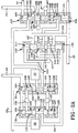
- Figure 2A is an enlarged portion of Figure 1, the outline of which is delineated by the chain line identified as "FIG-2A" and depicting a representative control valving arrangement incorporating the present invention;
- Figure 2B is also an enlarged portion of Figure 1, the outline of which is delineated by the chain line identified as "FIG-2B" and depicting the source of hydraulic pressure, a pressure regulator assembly, a clutch assembly, the transmission gearing, a cooler and a lube system;
- Figure 2C is also an enlarged portion of Figure 1, the outline of which is delineated by the chain line identified as "FIG-2C" and depicting a selector valve, a forward-reverse control assembly and two of the cascaded shift valves and their related accumulators;
- Figure 2D is also an enlarged portion of Figure 1, the outline of which is delineated by the chain line identified as "FIG-2D" and depicting the remaining two cascaded selector valves and their associated accumulators;
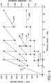
- Figure 3 is a graph representing operating parameter values present during upshifts in a transmission control incorporating the present invention;
- Figure 4 is a graph representing operating parameter values present during downshifts in a transmission control incorporating the present invention; and
- Figure 5 is a graph representing typical pressure curves from the solenoid valves that control the ratio interchanges and trim pressure bias of the transmission control incorporating the present invention.
- The overall power transmission and transmission control embodying the concepts of the present invention is depicted diagrammatically, and designated by the
numeral 10, in Figure 1. The gearing portion of the transmission is represented at 11 and is preferably constructed in accordance with the teaching of US Patent No. 5,009,118, incorporated herein by reference. However, other transmissions can also benefit from the present invention. Pressurised hydraulic fluid is provided to the transmission control by a conventional,positive displacement pump 14 which draws hydraulic fluid from areservoir 15 through apassage 17 for delivery to amain line conduit 18. Aconventional pressure regulator 20 controls the fluid pressure in themain line conduit 18. The excess fluid -- that is, fluid not needed for transmission control and clutch operation -- delivered by thepump 14 is directed by anoverage passage 21 to a conventional torque converter andclutch assembly 23. A conventionalexhaust regulator valve 22 limits the fluid pressure at the torque converter andclutch assembly 23. The fluid flowing from theassembly 23 is directed through a cooler and a lubrication distribution (LUBE) system, so designated on Figures 1 and 2A of the drawings. The pressure in the lubrication system circuit is established by aconventional regulator valve 26. - The
main line conduit 18 is connected, bybranch 18A with amanual selector valve 24, bybranch 18B to a forward-reverse control assembly 25, bybranch 18C to the torque converter andclutch assembly 23, and bybranch 18D to first and second normally open pulse width modulated (PWM)solenoid valves boost control valve 30. The main line pressure distributed to the torque converter andclutch assembly 23 is utilised to engage the clutch in a well known manner. Themanual selector valve 24 is adapted to be manipulated in a well known manner to distribute the pressurised hydraulic fluid in themain line conduit 18 in accordance with the drive ratio selected by the operator. Themanual selector valve 24 has alongitudinal bore 31 in which aspool valve member 33 is slidably disposed. Thespool valve member 33 has spacedlands branch 18A of themain line conduit 18 to areverse passage 37 when reverse drive "R" is selected by the operator and to aforward passage 38 when any forward drive "D1" through "D5" is selected by the operator. - When the operator desires to limit the number of forward drive ratios to less than the maximum number available (five with the depicted control), the
manual selector valve 24 can be manipulated to the forward drive conditions "D4" through "D1". In the "D4" condition, main pressure is distributed to a "D4"passage 40 as well as theforward passage 38. All of the other passages leading from theselector valve 24 are exhausted. In the "D3" condition, main line pressure is distributed to a "D3"passage 41, as well as the "D4"passage 40 and theforward passage 38. In the "D2" condition, main line pressure is distributed to a "D2"passage 43 as well as the "D3"passage 41, the "D4"passage 40 and theforward passage 38. In the "D1" condition, main pressure is distributed to a "D1"passage 44 as well as the "D2"passage 43, the "D3"passage 41, the "D4"passage 40 and theforward passage 38. The effect of the pressure inpassages - The
forward passage 38 and thereverse passage 37 as well as themain line conduit 18 are distributed to the forward-reverse control assembly 25 which is effective to establish the power flow through the transmission in a well known manner. The above described US Patent No. 5,009,118 utilises a synchroniser to establish the forward or reverse power path. The forward-reverse control assembly 25 is preferably constructed in accordance with the assembly described in US Patent No. 5,233,878, incorporated herein by reference. - The transmission control provides for controlling the engagement and disengagement of the friction torque transfer devices required to establish the ratios from the
gearing 11 in the transmission. The ratio interchange control is provided by fourshift valves 47A through 47D, fourexhaust valves 48A through 48D and fiveaccumulators 50A through 50E. - The transmission has five friction torque transfer devices in the nature of clutches designated "C1" through "C5". One of the clutches is engaged for each drive ratio while the remaining clutches are disengaged. The clutch "C3" provides both the third forward speed and the reverse speed. A two
position shuttle valve 51 is operable to connect the proper passage to the "C3" clutch. - The
shift valve 47A controls the one/two ratio interchange and employs aspool valve member 53A having spacedlands bore 58A which communicates with a firstclutch feed passage 60, a first clutch apply passage 61, a secondclutch feed passage 63A, a firstclutch exhaust passage 64A, the hydraulicfluid return line 65A, the "D1"passage 44 and agovernor passage 67. Thespool 53A is biased toward thegovernor passage 67 by aspring 68A, disposed in a chamber 70, that is located at one end of thebore 58A adjacent theland 57A. The firstclutch feed passage 60 is connected with the forward-reverse control assembly 25 which is effective to distribute main line hydraulic pressure thereto when theforward passage 38 is pressurised. - In the spring set position shown, -- that is, when the spool valve members are disposed solely in response to the biasing action of the spring -- the
shift valve 47A distributes main pressure in the firstclutch feed passage 60 betweenlands accumulator chamber 71A which is a component of theaccumulator 50A. Theaccumulator 50A also includes aplug 73A, atrim chamber 74A and aspring 75A. Theaccumulator 50A is effective to control the pressure rise in the clutch "C1" during engagement in a well known manner. Thetrim chamber 74A is pressurised by a controlled pressure in atrim passage 77, which has an effect on the pressure rise in theaccumulator chamber 71A and therefore the engagement time of the clutch "C1" as represented by the pressure in first clutch apply passage 61. - In the pressure set position -- that is, the position of the spool valve members when the pressure in the
governor passage 67 overcomes thespring 68A --the firstclutch feed passage 60 is connected betweenlands clutch feed passage 63A which is in fluid communication with the two/threeshift valve 47B where it is closed byland 55B onspool valve member 53B. However, when thespool valve member 53B is in the spring set position depicted, an offsetpassage 78B connects the second clutch feed passage 63 and the space betweenlands passage 61B which is effective, when pressurised, to enforce engagement of the second clutch "C2". The engagement time of the second clutch "C2" is affected by theaccumulator 50B in the same manner as described previously herein with respect to theaccumulator 50A. - The pressure in the second clutch feed passage 63 is also ported to react with a
spool valve member 81A in theexhaust valve 48A. Thespool valve member 81A includes a pair of spacedlands spring 85A biases thespool valve member 81A to one end of abore 87A invalve 48A. The firstclutch exhaust passage 64A communicates with thebore 87A through arestriction 88A which is connected with an exhaust, or hydraulic fluid return line, 90A. When theshift valve 47A is initially moved to the pressure set position, the clutch "C1" will begin to exhaust through therestriction 88A. However, when the pressure in secondclutch feed passage 63A is at a level sufficient to overcome thespring 85A, thespool valve member 81A will connect firstclutch exhaust passage 64A directly to the hydraulicreturn line passage 90A freely to exhaust the clutch "C1". The trigger pressure of theexhaust valve 48A is substantially equal to the minimum pressure required for the clutch "C2" to begin transmitting torque. - As the pressure in the
governor passage 67 continues to increase, theshift valves respective accumulators 50 andexhaust valves 48 will control the timing of the interchanges. It should be appreciated that the higher ratio clutches cannot be engaged until the next lower clutch has first been engaged. This is commonly termed a cascading pressure control. It should also be evident that the shuttle valve 51 (Figure 2C) is effective to connect third clutch applypassage 61C to the clutch "C3" and thetrim chamber 74C in theaccumulator 50C during a two/three ratio interchange. During downshifting when a clutch is engaged, the higher ranking clutches will be disengaged. - If the transmission is in second gear --that is, the
shift valve 47A has upshifted, and the pressure in thegovernor passage 67 is reduced to a level sufficient to permit thespring 68A to reset (downshift) theshift valve 47A to the spring set position, the second clutch "C2" will be exhausted through thereturn line 65A while the clutch "C1" is engaged by pressure in firstclutch feed passage 60 being communicated betweenlands - The reverse ratio is engaged by the
manual selector valve 24 being shifted to the reverse position to pressurise a reverse applypassage 93 which is fed through the forward-reverse control assembly 25. When the reverse applypassage 93 is pressurised, theshuttle valve 51 is moved to close the third clutch applypassage 61C from theshift valve 47C and simultaneously connect the reverse applypassage 93 with the clutch "C3" and theaccumulator 50C. The reverse applypassage 93 is also connected with first andsecond interlock valves respective solenoid valves - The
solenoid valves solenoid valves solenoid valve PWM solenoid valves transmission control 10 and programmed in a conventional manner to establish the various pressures. Such computers and the operating or control algorithms are well known. Thesolenoid valve 27 is controlled at one pressure schedule while thesolenoid valve 28 is controlled at another pressure schedule during upshifting. The difference in the schedules permits thesolenoid valve 27 to operate along theline 97 of the curve shown in Figure 5 and also permits thesolenoid valve 28 to operate along theline 98 in that same figure. As seen in Figure 5, the pressure output ofsolenoid valve 27 increases before the pressure output of thesolenoid valve 28. The purpose for these different schedules will be explained in conjunction with the description ofvalves - The
first interlock valve 94 includes aspool valve member 100 having spacedlands diameter bore 105. As best seen in Figure 2A, the second andthird lands first land 101 and cooperate with the stepped diameter bore 105 to define aninterlock chamber 107. Thespool valve member 100 is urged toward one end of thebore 105 by aspring 108 disposed inchamber 110 and compressed between aplug 111 and theland 104. In the spring set position shown, the output pressure ofsolenoid valve 27 is in fluid communication with thebore 105 between thelands control passage 113 which is in fluid communication with acontrol chamber 114 formed on agovernor shuttle valve 115. Agovernor feed passage 117 branches from thecontrol passage 113 and is also connected with thegovernor shuttle valve 115 betweenlands - The
second interlock valve 95 includes aspool valve member 118 having spacedlands diameter bore 125. As best seen in Figure 2, the second andthird lands first land 120 and cooperate with the stepped diameter bore 125 to define aninterlock chamber 126. Thespool valve member 118 is urged toward one end of thebore 125 by aspring 127 disposed in achamber 128 and compressed between aplug 130 and theland 123. In the spring set position shown, the output pressure of thesolenoid valve 28 is in fluid communication with thebore 125 between thelands control passage 131 which is in fluid communication with acontrol chamber 133 formed on thegovernor shuttle valve 115. Agovernor feed passage 134 branches from thecontrol passage 131 and is also connected with thegovernor shuttle valve 115. - The
interlock valves passage 93 which, as previously explained, is pressurised through themanual selector valve 24 and the forward-reverse control assembly 25 when the reverse drive is selected by the operator. The reverse applypassage 93 communicates with the face of thelands spool valve members bores chambers spring chambers fluid return line 137. - When the reverse apply
passage 93 is pressurised, thespool valve members exhaust 135 will be closed by thelands interlock valves interlock chambers respective solenoid valves control passages exhaust 137. During normal operation, thesolenoid valves - The
governor shuttle valve 115 includes aspool valve member 138 having threelands bore 144 between thecontrol chambers bore 144 is disposed in fluid communication with the governor feedpassages governor pressure passages trim boost passage 148. Bothgovernor pressure passages primary boost passage 150 which, in turn, communicates with theprimary governor passage 67. Thespool valve member 138 ingovernor shuttle valve 115 is positioned by the pressure in theopposed control chambers solenoid valve 27 increases before the pressure fromsolenoid valve 28. Therefore, thegovernor shuttle valve 115, during normal forward operation, will be disposed in the position shown in Figures 1 and 2A. So disposed, the pressure fromsolenoid valve 27 is directed viapassages governor passage 67 and theprimary boost passage 150. Thegovernor pressure passage 147 is closed at theland 140 and the output pressure of thesolenoid valve 28 is directed viapassages trim boost passage 148. - The secondary
trim boost passage 148 is connected for fluid communication with one side of aboost plug 151, andprimary boost passage 150, throughgovernor passage 67 is connected for fluid communication with the opposite side ofboost plug 151. Theboost plug 151 is a component of the accumulator trimboost control valve 30, as depicted in Figure 2A. Theboost plug 151 co-operates with abore 153 to define aprimary chamber 154, connected withgovernor passage 67 and thereby indirectly withprimary boost passage 150. Asecondary chamber 155 is connected in fluid communication with the secondarytrim boost passage 148. The accumulator trimboost control valve 30 also includes aregulator valve 157 which is connected with theboost plug 151 through a pin and stop 158, and a spring 160. Theregulator valve 157 includes avalve spool member 161 having spacedlands bore 165. Thebore 165 is connected with the main linepressure conduit branch 18D, thetrim passage 77 and a pair of exhaust, or hydraulic fluid return lines 167. Thetrim passage 77 is connected to acontrol chamber 170 defined between thelands restriction 168. - Fluid pressure in
trim passage 77 will urge thevalve spool member 161 against the spring 160 in a direction to close the main linepressure conduit branch 18D atland 163 and open theexhaust 167 previously closed byland 164. This action will control the pressure in thetrim passage 77 in a well-known manner. Fluid pressure operating on theboost plug 151 will control the amount of compression in the spring 160 and therefore, the pressure level at which theregulator valve 157 maintains the pressure intrim passage 77. When theboost plug 151 is urged against the spring 160 by pressure inprimary chamber 154, as determined by thesolenoid valve 27, the pressure level intrim passage 77 will be at a high level, and when bothchambers trim passage 77 will be at a low level. The pressure level intrim passage 77 will provide a bias pressure for the trim chamber 74 in the accumulators 50 (through trim passage 77) -- thereby providing a control pressure for the clutches "C1" through "C5" in a well-known manner. - With the vehicle engine operating, the
pump 14, in conjunction with thepressure regulator 20, provides pressurised hydraulic fluid. With theselector valve 24 positioned for "D5", the vehicle will respond to a throttle increase by the operator to provide forward motion. Thesolenoid valve 27 will produce an output pressure in accordance with the curves shown in Figures 3 to 5. Figure 3 depicts the pressure output of thesolenoid valves line 171 and for one-hundred (100%) percent throttle byline 173. Figure 3 also depicts curves, or lines, which define the engine speed range for the ratios selected in the transmission. With reference tolines 172 in Figure 3 the engine speed will decrease when an upshift occurs. To accomplish the engine decrease, the on-coming clutch -- for example: clutch "C2" during a one/two shift, must absorb the engine inertia. To accommodate this, the clutch timing is controlled by the trim boost pressure reflected in the trim chamber 74 of theappropriate accumulator 50. The curves shown in Figure 4 represent values similar to those in Figure 3 during downshifts. The curves shown here, however, represent closed throttle and one-hundred (100%) percent throttle positions. - As best seen in Figure 5, the
solenoid valve 27 is controlled to provide a pressure increase, during upshifting, before thesolenoid valve 28. This function is provided in a well-known manner by the digital computer which provides the control function of the vehicle in response to various input signals or data as previously described. When the pressure level ofsolenoid valve 27 increased, thegovernor shuttle valve 115 assumes the position shown in Figures 1 and 2. Thegovernor shuttle valve 115 will not be shifted from this position, during forward operation, as long as thesolenoid valves solenoid valve 27 is directed to thegovernor passage 67, to act on the shift valves 47, and to theprimary chamber 154 in the accumulator trimboost control valve 30, to establish the output pressure level of theregulator valve 157 and the boost pressure at eachaccumulator 50, as communicated throughtrim passage 77. As seen in Figures 3 and 5, this creates a step function for the governor pressure while the accumulator trim boost pressure cycles between high and low values. - The pressure output level of the
solenoid valve 28 lags that ofsolenoid valve 27, but achieves the same levels. The pressure output of thesolenoid valve 28 is directed to thesecondary boost chamber 155. When the pressure ofsolenoid valve 28 is equal to the pressure ofsolenoid valve 27, the trim boost pressure will be at a minimum as established by the biasing action of the spring 160 and the reduction in the projected area of theboost plug 151 resulting from the cross sectional area of pin and stop 158. This permits the use of a single accumulator trimboost control valve 30 for all of theaccumulators 50. Because theshift valves 47A through 47D are cascaded, the trim boost pressure on therespective accumulators 50A through 50D is effective only during the shift sequence controlled by the upshifting valve. To eliminate the pin and stop 158 from the trim boost pressure determination, equal diameter pin extensions can be incorporated on both sides of theboost plug 151 with one pin end passing into thebore 165 and the other pin end disposed in a bore in the bottom ofprimary chamber 154 and being connected to exhaust. - As the vehicle speed increases, the pressure in
governor passage 67 will increase in accordance with the schedule depicted in Figure 3. At a predetermined speed, depending on throttle position, the output pressure ofsolenoid valve 27 will be increased to effect upshifting of theshift valve 47A -- thereby causing the clutch "C2" to be pressurised and the clutch "C1" to be exhausted through theexhaust valve 48A to exhaust 90A. Theboost plug 151 is forced against the spring 160 to established an appropriate pressure, depending on vehicle parameters, within thetrim chamber 74B of theaccumulator 50B to control the pressure rise schedule of the clutch "C2". The remaining trim chambers 74 will also be pressurised but theaccumulators 50 connected therewith are inoperative at that stage. The pressure output of thesolenoid valve 28 will then be increased to cause theboost plug 151 to be pressure balanced and the output pressure of theregulator valve 157 to reduce to the minimum value. - A further increase in the vehicle speed, at a constant throttle setting, will result in increased pressure in the
governor passage 67 at the desired shift speed as shown by the curves in Figures 3 and 5. At a predetermined pressure, theshift valve 47B will be upshifted and the trim boost pressure in thetrim passage 77 will be increased such that theaccumulator 50C will be effective to control the engagement pressure schedule at the clutch "C3" while the clutch "C2" is exhausted through thevalve 48B to theexhaust 90B. Figure 5 shows the output pressure ofsolenoid valve 27 atline portion 174, is at a pressure level greater than the output pressure ofsolenoid valve 28 at theline portion 175. This establishes the trim boost pressure "T" intrim passage 77 that is available in thetrim chamber 74C during the two/three ratio interchange. When the shift is completed and the output pressure ofsolenoid valve 28 is increased to a level equal to the outlet pressure ofsolenoid valve 27, the trim boost pressure intrim passage 77 will decrease to a minimum value as determined by the spring 160. - As the vehicle speed continues to increase, the
shift valve 47C will reach the shift point to control the three/four ratio interchange through the engagement of clutch "C4", as controlled by theaccumulator 50D, while theexhaust valve 48C controls the disengagement of the clutch "C3". The trim boost pressure will be controlled in the manner previously described. The four/five ratio interchange, resulting from an upshift at theshift valve 47D, represented by the engagement of the clutch "C5", as controlled by theaccumulator 50E, and the disengagement of the clutch "C4" will occur in the manner as described above for the other ratio interchanges. - It should be apparent that the accumulator trim
boost control valve 30 is effective to control the trim pressure at each upshift ratio interchange. The combination of theboost plug 151 and thesolenoid valves boost control valve 30 in providing this feature. Closed throttle downshift ratio interchanges are made without trim boost inasmuch as engine torque is minimal during this event. The curves of Figure 5 also show the hysteresis "H" between the upshift and the downshift schedule. For example, the one/two upshift begins at thepoint 177A oncurve 97 while the two/one downshift begins at thepoint 178A oncurve 97. Likewise, the two/three upshift occurs at thepoint 177B while the three/two downshift occurs at thepoint 178B. The other upshift and downshift points are evident on thecurve 97. - The difference between the upshift and downshift points represents the hysteresis. This function (hysteresis) is provided to prevent "hunting" by the transmission control when the vehicle is operated close to any shift point. While the hysteresis function can be provided in many ways, the most common is to provide a differential area on the shift valve which is subjected to the on-coming clutch pressure after the shift. With this structure, the forces holding the valve in the upshifted position are greater after the shift such that the control pressure in
governor passage 67 must be at a lower level when a downshift occurs. - The upshift schedules at fifty percent and one-hundred percent throttle, represented by governor pressure schedules and engine speed curves, are shown in Figure 3. As will be apparent from reviewing the curves shown, the engine speed is higher during the ratio interchange and the interchanges occur at higher engine speeds as the throttle setting is increased. The downshift schedules of zero percent and one-hundred percent throttle, represented by governor pressure schedules and engine speed curve, are shown in Figure 4. As is apparent from the curves, the downshift vehicle speed increases as the throttle position is increased. These are conventional shift schedules.
- The transmission can be limited to less than all of the forward speed ratios by manipulation of the
manual selector valve 24. For example, if the operator does not wish the transmission to reach the fifth forward speed ratio, the manual valve will be moved to the "D4" position. In this position, the "D4"passage 40 will be pressurised. The pressure in this "D4"passage 40 is directed to thechamber 70D of theshift valve 47D. This pressure acts on theland 57D to assist thespring 85D in resisting the upshifting of theshift valve 47D. The pressure in thegovernor passage 67 will not be sufficient to force the upshifting of theshift valve 47D. - Manipulation of the
manual selector valve 24 to the other forward ratio positions represented by "D3" through "D1" will result in limiting the upshifting of the transmission to the third forward through first forward ratios respectively. In "D3", the "D3"passage 41 and thereforechamber 70C will be pressurised to prevent the upshifting of theshift valve 47C such that the transmission control cannot energise the clutches "C4" and "C5". Likewise, the pressurisation of the "D2" and "D3"passages shift valves governor passage 67 is sufficient to shift the respective valves. The operator can downshift from any forward to a lower forward ratio through the manipulation of themanual selector valve 24. - The purpose of the
governor shuttle valve 115 is to direct the higher pressure output of the twosolenoid valves boost plug 151 and to thegovernor passage 67. When the control system is operating as intended, thesolenoid valve 27 will, at a predetermined portion of the cycle, provide a higher pressure than thesolenoid valve 28 during the upshift cycle. However, if thesolenoid valve 28 should inadvertently produce a higher pressure than thesolenoid valve 27, thecontrol chamber 133 will be at a higher pressure resulting in thegovernor shuttle valve 115 being forced into thecontrol chamber 114. In this position, thecontrol passage 131 is connected to thegovernor pressure passage 147 betweenlands governor feed passage 117 is connected with the secondarytrim boost passage 148 between thelands solenoid valves - If either
solenoid valve passage 93 is pressurised. This results in theshuttle valve 51 being moved to direct the fluid pressure in reverse applypassage 93 to the clutch "C3". Also during a shift to reverse, the forward-reverse control assembly 25 will condition the necessary mechanism (that is, a synchroniser) to the proper position. - The pressure in reverse apply
passage 93 will also act on thelands spool valve members respective springs spool valve members interlock chambers solenoid valves solenoid valves respective interlock valve respective interlock chamber governor passage 67 andprimary boost passage 150. This will result in maximum trim boost pressure at theaccumulators 50 such that the operator will experience harsh shifting at all throttle conditions. This shift feel will continually remind the operator that some repair is required. However the operator will have the entire range of operation until the repairs are effected. - Also with this control, if either
solenoid valve shuttle valve 51 should become stuck in either extreme condition, the transmission will undergo harsh shifting, again alerting the operator to the need for repair. If theshuttle valve 51 malfunctions in the centre position, all the transmission shifts will be soft, suggesting slipping clutches, which will alert the operator to the need for repair. Malfunctions in the accumulator trimboost valve 30 will result in harsh shifting when continual high trim boost pressure is present and in soft shifting if continual low trim boost pressure is present. As explained above, these conditions alert the operator to the need for repair. - The disclosures in United States patent application no. 073,238 from which this application claims priority, and the abstract accompanying this application, are incorporated herein by reference.
Claims (3)
- A transmission control comprising regulator valve means (157) for providing a trim pressure fluid for a plurality of accumulators (50) including a boost plug (151); a shuttle valve (51) for selectively directing pressurised fluid to first and second ends of the boost plug and for directing pressurised fluid to a governor passage (67); a first interlock valve (94) for selectively directing pressurised fluid from a first solenoid valve (27) through the shuttle valve to the first end of the boost plug and the governor passage; and a second interlock valve (95) for selectively directing pressurised fluid from a second solenoid valve (28) through the shuttle valve to the second end of the boost plug when the pressurised fluid from the first solenoid valve is at a level greater than the pressurised fluid from the second solenoid valve, the boost plug being responsive to the fluid from the first and second interlock valves to switch the fluid from the second interlock valve to the first end of the boost plug when the pressure level of the fluid directed from the second interlock valve is greater than the fluid directed from the first interlock valve.
- A transmission control as claimed in Claim 1 further comprising manual valve means (24) for directing fluid to establish forward and reverse drive ratios; and wherein the first interlock valve (94) includes a first interlock chamber (107) and the second interlock valve (95) includes a second interlock chamber (126), both the first and second interlock chambers being connected with the fluid from the first and second solenoid valves (27,28) respectively when the reverse drive ratio is selected by the manual valve means.
- A transmission control comprising a source of fluid pressure including a pump (14) and a system regulator valve (20); a plurality of fluid operated selectively engageable torque transmitting means (C1-5) for establishing a plurality of speed ratios in a transmission, respective ones of the torque transmitting means being interchanged during a change of ratios; a plurality of shift valves (47) for controlling the interchange of ratios each including an accumulator (50) for assisting in controlling interchange time, each accumulator having a trim chamber (74) for providing a reaction pressure during the interchanges; trim boost supply means (30) for supplying and controlling a trim boost pressure delivered to the trim chambers including a pressure regulator (157) for supplying pressurised fluid and a boost plug (151) having a first chamber (154) for increasing the fluid pressure at the pressure regulator and a second chamber (155) for counteracting the first chamber for counteracting the first chamber; and solenoid valve means (27,28) for selectively supplying pressure to the first chamber when each ratio interchange is initiated and to the second chamber prior to the occurrence of a subsequent ratio interchange.
Applications Claiming Priority (2)
| Application Number | Priority Date | Filing Date | Title |
|---|---|---|---|
| US73238 | 1993-06-07 | ||
| US08/073,238 US5399130A (en) | 1993-06-07 | 1993-06-07 | Transmission control with electronic governor and trim boost |
Publications (3)
| Publication Number | Publication Date |
|---|---|
| EP0628755A2 true EP0628755A2 (en) | 1994-12-14 |
| EP0628755A3 EP0628755A3 (en) | 1996-01-03 |
| EP0628755B1 EP0628755B1 (en) | 1998-08-12 |
Family
ID=22112578
Family Applications (1)
| Application Number | Title | Priority Date | Filing Date |
|---|---|---|---|
| EP94201357A Expired - Lifetime EP0628755B1 (en) | 1993-06-07 | 1994-05-13 | Transmission control |
Country Status (5)
| Country | Link |
|---|---|
| US (1) | US5399130A (en) |
| EP (1) | EP0628755B1 (en) |
| JP (1) | JPH06346965A (en) |
| CA (1) | CA2122462C (en) |
| DE (1) | DE69412364T2 (en) |
Families Citing this family (19)
| Publication number | Priority date | Publication date | Assignee | Title |
|---|---|---|---|---|
| US5509868A (en) * | 1994-09-13 | 1996-04-23 | General Motors Corporation | Governor interlock valve |
| US5492028A (en) * | 1994-09-22 | 1996-02-20 | General Motors Corporation | Trimmer valve with flow retention |
| US5492210A (en) * | 1994-09-22 | 1996-02-20 | General Motors Corporation | Ratio interchange control valving |
| US5640322A (en) * | 1994-12-15 | 1997-06-17 | General Motors Corporation | System for controlling the operation of a vehicular transmission |
| WO1997001310A1 (en) * | 1995-06-29 | 1997-01-16 | The Procter & Gamble Company | Elastic back wrap having diamond-shaped thermal pattern and anti-slip means |
| AU6173796A (en) * | 1995-06-29 | 1997-01-30 | Procter & Gamble Company, The | Thermal neck wrap having wing shape and means for position maintenance |
| US5728058A (en) * | 1995-06-29 | 1998-03-17 | The Procter & Gamble Company | Elastic knee wrap |
| US5738602A (en) * | 1995-10-24 | 1998-04-14 | Honda Giken Kogyo Kabushiki Kaisha | Oil pressure control system for automatic vehicle transmission |
| US5674270A (en) * | 1996-06-27 | 1997-10-07 | The Procter & Gamble Company | Thermal pad having a common attachment and oxygen permeable side |
| US5980562A (en) * | 1996-07-26 | 1999-11-09 | The Procter & Gamble Company | Elastic back wrap having diamond-shaped thermal pattern and anti-slip means |
| US5738608A (en) * | 1996-08-19 | 1998-04-14 | General Motors Corporation | Hydraulic control for a multi-ratio transmission |
| US6776736B1 (en) * | 2002-01-10 | 2004-08-17 | Sonnax Industries, Inc. | Self-regulating reverse boost valve assembly |
| US7735395B2 (en) * | 2004-07-20 | 2010-06-15 | Gm Global Technology Operations, Inc. | External speed sensor and method |
| US7938060B2 (en) * | 2004-09-13 | 2011-05-10 | Southeastern Mills, Inc. | Breadcrumb manufacturing system and method |
| DE102005050489A1 (en) * | 2005-10-21 | 2007-04-26 | Zf Friedrichshafen Ag | Control valve arrangement for controlling a starting clutch of an automatic transmission |
| DE102005050493A1 (en) * | 2005-10-21 | 2007-04-26 | Zf Friedrichshafen Ag | Control valve arrangement for controlling a starting clutch of an automatic transmission |
| US7621837B2 (en) * | 2005-12-28 | 2009-11-24 | Aisin Aw Co., Ltd. | Hydraulic control apparatus for an automatic transmission |
| WO2019005551A1 (en) | 2017-06-30 | 2019-01-03 | Allison Transmission, Inc. | Control system and method thereof for multispeed transmission |
| US11181193B2 (en) | 2019-11-27 | 2021-11-23 | Allison Transmission, Inc. | Power off hydraulic default strategy |
Citations (7)
| Publication number | Priority date | Publication date | Assignee | Title |
|---|---|---|---|---|
| US4827806A (en) * | 1988-08-11 | 1989-05-09 | General Motors Corporation | Logic valving for a transmission control |
| US4903551A (en) * | 1987-02-25 | 1990-02-27 | Mitsubishi Jidosha Kogyo Kabushiki Kaisha | Failsafe hydraulic control system for vehicle automatic transmission |
| EP0356036A2 (en) * | 1988-08-02 | 1990-02-28 | Toyota Jidosha Kabushiki Kaisha | Hydraulic control device for automatic transmission for vehicle having clutch operable in two speed stages and two parallel hydraulic pressure supply passages therefor |
| US4936430A (en) * | 1988-04-04 | 1990-06-26 | Kabushiki Kaisha Daikin Seisakusho | Control hydraulic circuit for speed change clutch |
| US5083481A (en) * | 1990-09-17 | 1992-01-28 | Ford Motor Company | Electronically controlled automatic transmission |
| EP0476832A2 (en) * | 1990-09-14 | 1992-03-25 | Ford Motor Company Limited | Electronic control system for multiple ratio transmission including circuit pressure control |
| EP0525725A1 (en) * | 1991-07-31 | 1993-02-03 | Honda Giken Kogyo Kabushiki Kaisha | Apparatus for controlling oil pressure for vehicular automatic transmission |
Family Cites Families (3)
| Publication number | Priority date | Publication date | Assignee | Title |
|---|---|---|---|---|
| US4308764A (en) * | 1978-10-30 | 1982-01-05 | Aisin Warner, K.K. | Shift control device for automatic transmission |
| JPS55149454A (en) * | 1979-05-10 | 1980-11-20 | Aisin Warner Ltd | Automatic transmission controller |
| JP2912009B2 (en) * | 1990-11-27 | 1999-06-28 | ジャトコ株式会社 | Transmission control device |
-
1993
- 1993-06-07 US US08/073,238 patent/US5399130A/en not_active Expired - Fee Related
-
1994
- 1994-04-28 CA CA002122462A patent/CA2122462C/en not_active Expired - Fee Related
- 1994-05-13 DE DE69412364T patent/DE69412364T2/en not_active Expired - Fee Related
- 1994-05-13 EP EP94201357A patent/EP0628755B1/en not_active Expired - Lifetime
- 1994-06-07 JP JP6125457A patent/JPH06346965A/en active Pending
Patent Citations (7)
| Publication number | Priority date | Publication date | Assignee | Title |
|---|---|---|---|---|
| US4903551A (en) * | 1987-02-25 | 1990-02-27 | Mitsubishi Jidosha Kogyo Kabushiki Kaisha | Failsafe hydraulic control system for vehicle automatic transmission |
| US4936430A (en) * | 1988-04-04 | 1990-06-26 | Kabushiki Kaisha Daikin Seisakusho | Control hydraulic circuit for speed change clutch |
| EP0356036A2 (en) * | 1988-08-02 | 1990-02-28 | Toyota Jidosha Kabushiki Kaisha | Hydraulic control device for automatic transmission for vehicle having clutch operable in two speed stages and two parallel hydraulic pressure supply passages therefor |
| US4827806A (en) * | 1988-08-11 | 1989-05-09 | General Motors Corporation | Logic valving for a transmission control |
| EP0476832A2 (en) * | 1990-09-14 | 1992-03-25 | Ford Motor Company Limited | Electronic control system for multiple ratio transmission including circuit pressure control |
| US5083481A (en) * | 1990-09-17 | 1992-01-28 | Ford Motor Company | Electronically controlled automatic transmission |
| EP0525725A1 (en) * | 1991-07-31 | 1993-02-03 | Honda Giken Kogyo Kabushiki Kaisha | Apparatus for controlling oil pressure for vehicular automatic transmission |
Also Published As
| Publication number | Publication date |
|---|---|
| CA2122462A1 (en) | 1994-12-08 |
| DE69412364D1 (en) | 1998-09-17 |
| US5399130A (en) | 1995-03-21 |
| EP0628755B1 (en) | 1998-08-12 |
| DE69412364T2 (en) | 1998-12-24 |
| EP0628755A3 (en) | 1996-01-03 |
| CA2122462C (en) | 1997-12-23 |
| JPH06346965A (en) | 1994-12-20 |
Similar Documents
| Publication | Publication Date | Title |
|---|---|---|
| EP0628755B1 (en) | Transmission control | |
| CA1168129A (en) | Hydraulic control for a power transmission | |
| EP0691487B1 (en) | Electronic and hydraulic control system of a 4-speed automatic transmission for automotive vehicle | |
| EP0294033B1 (en) | Transmission control circuit with a clutch priority valve | |
| KR0168298B1 (en) | Hydraulic control system of automatic transmission for a vehicle | |
| EP0626912B1 (en) | A shift control device of a hydraulic control system for automatic transmission | |
| EP0655036B1 (en) | Hydraulic control system for 4-speed automatic transmission | |
| EP0707163B1 (en) | Shift control system for a multiple ratio automatic transmission with manual ratio ranges | |
| EP1162392A2 (en) | Swap-shift control system for multiple ratio transmissions | |
| US5836845A (en) | Hydraulic pressure control apparatus for an automatic transmission | |
| EP1061292A2 (en) | Relay valve with latch area for controlling a friction device | |
| US5509868A (en) | Governor interlock valve | |
| US6464609B1 (en) | Hydraulic control for a six-speed automatic transmission | |
| US5540634A (en) | Hydraulic control system of four-speed automatic transmission for automotive vehicle | |
| US5375483A (en) | Directional control valve of a hydraulic control system for automatic transmission | |
| US4418587A (en) | Hydraulic system pressure control for a power transmission | |
| US5651751A (en) | Shift control system of an automatic transmission used in a vehicle | |
| EP0678690B1 (en) | Hydraulic control system of a 4-speed automatic transmission for vehicle | |
| US5496231A (en) | Hydraulic control for a multi-speed power transmission | |
| US5492210A (en) | Ratio interchange control valving | |
| US5569116A (en) | Electronic and hydraulic system of five speed automatic transmission | |
| US5492028A (en) | Trimmer valve with flow retention | |
| US5669853A (en) | Hydraulic control system for four-speed automatic transmission of automotive vehicle | |
| US5667453A (en) | Hydraulic control system of an automatic transmission used in a vehicle | |
| EP0684910B1 (en) | A hydraulic control system for automatic transmission |
Legal Events
| Date | Code | Title | Description |
|---|---|---|---|
| PUAI | Public reference made under article 153(3) epc to a published international application that has entered the european phase |
Free format text: ORIGINAL CODE: 0009012 |
|
| AK | Designated contracting states |
Kind code of ref document: A2 Designated state(s): DE FR GB IT |
|
| PUAL | Search report despatched |
Free format text: ORIGINAL CODE: 0009013 |
|
| AK | Designated contracting states |
Kind code of ref document: A3 Designated state(s): DE FR GB IT |
|
| 17P | Request for examination filed |
Effective date: 19960703 |
|
| GRAG | Despatch of communication of intention to grant |
Free format text: ORIGINAL CODE: EPIDOS AGRA |
|
| 17Q | First examination report despatched |
Effective date: 19971002 |
|
| GRAG | Despatch of communication of intention to grant |
Free format text: ORIGINAL CODE: EPIDOS AGRA |
|
| GRAH | Despatch of communication of intention to grant a patent |
Free format text: ORIGINAL CODE: EPIDOS IGRA |
|
| GRAH | Despatch of communication of intention to grant a patent |
Free format text: ORIGINAL CODE: EPIDOS IGRA |
|
| ITF | It: translation for a ep patent filed |
Owner name: BARZANO' E ZANARDO ROMA S.P.A. |
|
| GRAA | (expected) grant |
Free format text: ORIGINAL CODE: 0009210 |
|
| AK | Designated contracting states |
Kind code of ref document: B1 Designated state(s): DE FR GB IT |
|
| REF | Corresponds to: |
Ref document number: 69412364 Country of ref document: DE Date of ref document: 19980917 |
|
| ET | Fr: translation filed | ||
| PLBE | No opposition filed within time limit |
Free format text: ORIGINAL CODE: 0009261 |
|
| STAA | Information on the status of an ep patent application or granted ep patent |
Free format text: STATUS: NO OPPOSITION FILED WITHIN TIME LIMIT |
|
| 26N | No opposition filed | ||
| PGFP | Annual fee paid to national office [announced via postgrant information from national office to epo] |
Ref country code: GB Payment date: 20010424 Year of fee payment: 8 |
|
| PGFP | Annual fee paid to national office [announced via postgrant information from national office to epo] |
Ref country code: FR Payment date: 20010517 Year of fee payment: 8 |
|
| PGFP | Annual fee paid to national office [announced via postgrant information from national office to epo] |
Ref country code: DE Payment date: 20010626 Year of fee payment: 8 |
|
| REG | Reference to a national code |
Ref country code: GB Ref legal event code: IF02 |
|
| PG25 | Lapsed in a contracting state [announced via postgrant information from national office to epo] |
Ref country code: GB Free format text: LAPSE BECAUSE OF NON-PAYMENT OF DUE FEES Effective date: 20020513 |
|
| PG25 | Lapsed in a contracting state [announced via postgrant information from national office to epo] |
Ref country code: DE Free format text: LAPSE BECAUSE OF NON-PAYMENT OF DUE FEES Effective date: 20021203 |
|
| GBPC | Gb: european patent ceased through non-payment of renewal fee |
Effective date: 20020513 |
|
| PG25 | Lapsed in a contracting state [announced via postgrant information from national office to epo] |
Ref country code: FR Free format text: LAPSE BECAUSE OF NON-PAYMENT OF DUE FEES Effective date: 20030131 |
|
| REG | Reference to a national code |
Ref country code: FR Ref legal event code: ST |
|
| PG25 | Lapsed in a contracting state [announced via postgrant information from national office to epo] |
Ref country code: IT Free format text: LAPSE BECAUSE OF NON-PAYMENT OF DUE FEES;WARNING: LAPSES OF ITALIAN PATENTS WITH EFFECTIVE DATE BEFORE 2007 MAY HAVE OCCURRED AT ANY TIME BEFORE 2007. THE CORRECT EFFECTIVE DATE MAY BE DIFFERENT FROM THE ONE RECORDED. Effective date: 20050513 |