EP0628506B1 - Device to draw threads between a beam and a winding machine - Google Patents
Device to draw threads between a beam and a winding machine Download PDFInfo
- Publication number
- EP0628506B1 EP0628506B1 EP94107941A EP94107941A EP0628506B1 EP 0628506 B1 EP0628506 B1 EP 0628506B1 EP 94107941 A EP94107941 A EP 94107941A EP 94107941 A EP94107941 A EP 94107941A EP 0628506 B1 EP0628506 B1 EP 0628506B1
- Authority
- EP
- European Patent Office
- Prior art keywords
- thread
- threads
- shaped chamber
- broken
- box
- Prior art date
- Legal status (The legal status is an assumption and is not a legal conclusion. Google has not performed a legal analysis and makes no representation as to the accuracy of the status listed.)
- Expired - Lifetime
Links
- 238000004804 winding Methods 0.000 title claims description 30
- 238000002347 injection Methods 0.000 claims description 4
- 239000007924 injection Substances 0.000 claims description 4
- 230000001133 acceleration Effects 0.000 claims 1
- 239000004753 textile Substances 0.000 description 6
- 238000000034 method Methods 0.000 description 4
- 125000006850 spacer group Chemical group 0.000 description 2
- 238000004891 communication Methods 0.000 description 1
- 230000006835 compression Effects 0.000 description 1
- 238000007906 compression Methods 0.000 description 1
- 230000001419 dependent effect Effects 0.000 description 1
- 239000000428 dust Substances 0.000 description 1
- 239000011521 glass Substances 0.000 description 1
- 238000009434 installation Methods 0.000 description 1
- 238000009940 knitting Methods 0.000 description 1
- 239000000463 material Substances 0.000 description 1
- 239000002184 metal Substances 0.000 description 1
- 238000012856 packing Methods 0.000 description 1
- 230000001105 regulatory effect Effects 0.000 description 1
- 239000000126 substance Substances 0.000 description 1
- 239000002699 waste material Substances 0.000 description 1
- 238000009941 weaving Methods 0.000 description 1
Images

Classifications
-
- B—PERFORMING OPERATIONS; TRANSPORTING
- B65—CONVEYING; PACKING; STORING; HANDLING THIN OR FILAMENTARY MATERIAL
- B65H—HANDLING THIN OR FILAMENTARY MATERIAL, e.g. SHEETS, WEBS, CABLES
- B65H51/00—Forwarding filamentary material
- B65H51/16—Devices for entraining material by flow of liquids or gases, e.g. air-blast devices
-
- B—PERFORMING OPERATIONS; TRANSPORTING
- B65—CONVEYING; PACKING; STORING; HANDLING THIN OR FILAMENTARY MATERIAL
- B65H—HANDLING THIN OR FILAMENTARY MATERIAL, e.g. SHEETS, WEBS, CABLES
- B65H2701/00—Handled material; Storage means
- B65H2701/30—Handled filamentary material
- B65H2701/31—Textiles threads or artificial strands of filaments
Definitions
- This invention concerns a device to draw threads being unwound between a beam and a winding machine, as set forth in the main claim.
- the invention is employed advantageously in cooperation with winding machines fed by beams of yarns and used downstream of textile processes such as continuous mercerisation, for instance.
- a plurality of threads or yarns being fed parallel to each other and coming from one or more beams is taken up at the same time by these winding machines.
- the invention is set to work advantageously for a pre-set limited time before the beginning of the continuous unwinding operation while the individual ends of the plurality of threads or yarns have to be brought to their corresponding winding heads to be anchored.
- the invention is also advantageously set to work automatically whenever at least one thread or yarn of the plurality of threads or yarns being unwound from the beam is broken.
- textile threads or yarns are meant materials consisting of continuous or discontinuous fibres of a natural or chemical origin as normally included in processes of the textile field.
- each packaged beam whether it contains tens or thousands of threads or yarns, entails the problem of having to be unwound when those threads or yarns are to be used singly thereafter.
- the preferred package is a bobbin, whether cylindrical or tapered, of various gauges according to the specific use.
- EP-A-0 427 032 discloses a winding machine to take up a plurality of textile threads or yarns being unwound parallel to each other at the same time from one or more package supports; this winding machine is positioned advantageously downstream of apparatuses which process the plurality of parallel threads or yarns.
- This machine includes a headstock for taking up and unwinding the package support or supports holding the plurality of threads or yarns, the supports being beams advantageously, and includes also a supporting structure to hold a plurality of winding heads in a number coordinated with the number of threads or yarns to be wound.
- a device disclosed in EP-A-0 492 505 was embodied to overcome these problems and especially the problem linked to the interception, drawing and taking-up of broken threads automatically during the operations.
- This device comprises for each thread between the beam and thread package a first guide tube followed by a switch and by a second guide tube; the second guide tube follows substantially the first guide tube.
- An aspirator unit of a type that maintains a negative pressure and, advantageously, a shears unit to shear threads are associated with the second guide tube.
- the switch When a feeler that monitors single threads signals that a thread is broken, the switch is rotated and puts the first guide tube in communication with the second guide tube, which is kept under a negative pressure by the aspirator unit.
- the beam continues unwinding while the broken thread is removed through the aspirator unit.
- This device entails several problems linked to the high costs of its embodiment and the installation of the necessary plant inasmuch as a great number of switches, guide tubes and relative accessories such as solenoids, sensors, etc. are required.
- this device requires a great consumption of energy since all the aspirator units are always working to keep the second guide tubes always under a negative pressure.
- the beam is never halted and the broken thread is not re-used and is only taken up to prevent it possibly becoming entangled with the other threads being unwound.
- This invention enables the capacity of the winding heads to be fully exploited by increasing the average working speed without causing problems.
- the invention enables the ends of the single threads to be brought to their respective thread packages for anchorage for the subsequent winding step; it also makes possible the automatic interception and positioning of any broken thread.
- a plurality of guide tubes equal in number to the threads on the beam is provided between the beam unwinding assembly and the winding machine.
- each guide tube coincides with its own switch means, a small roller for instance, fitted so as to correspond with the relative thread package.
- the guide tubes may consist of glass or a plastic or of metal.
- a device to draw broken threads cooperates with the plurality of guide tubes and consists of thread aspiration/ejection means, which are momentarily actuated and then generate a current of aspiration air towards the switch means within each tube.
- the device according to the invention is actuated for the first time at the beginning of the operations to draw the ends of the single threads until they have been brought to their respective thread package and is also actuated whenever at least one of the threads breaks during the winding operations.
- the current of air producing a negative pressure draws all the threads on the beam, whereas, if at least one thread breaks, the current of air draws that at least one broken thread and makes it unwind regularly from the beam, thus preventing that thread becoming entangled with the other threads being unwound.
- the actuation of the device in the second case is governed by the breakage of at least one thread as detected by the relative feeler associated with the thread package.
- the breakage is signalled to a managing and control assembly, which governs the winding machine and sends a stop signal in this case; this signal causes the beam and the winding machine to be halted gradually with a pre-set gradient of descent of speed.
- the device according to the invention includes for each thread a thread aspiration/ejection means which extends to work within the guide tube in question from the outside in a position at an angle towards the outlet. In this way, while the unbroken threads continue being wound onto their respective thread packages, the broken thread is drawn into the respective guide tube and brought to the switch means by the current of air passing through that guide tube.
- the machine operator can take the broken thread from the switch means, shear the excess thread and knot the end to the end wound on the corresponding thread package.
- the beam and the winding machine are then re-started with a pre-set gradient of increase of speed until they reach the normal running speed of the winding machine, while the action of negative pressure in the device according to the invention is stopped.
- a thread take-up chamber is associated with, and positioned immediately downstream of, each switch means so as to prevent any problems being created by the broken thread unwinding from the beam and drawn by the current of air of the device according to the invention.
- an assembly holding a buffer stock of compressed air and acting as a compensator is included between the guide tubes and the beam.
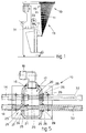
- a device 10 to draw threads 11 and/or broken threads 111 between a beam and a winding machine 13 is located between the beam and a plurality of guide tubes 14, which are positioned in close proximity to each otherso as not to take up space.
- Fig.1 is a part view of a winding machine 13 fed by a beam, which is not shown here but bears a plurality of threads 11; the threads 11 may be, for instance, fifty or one hundred in number or be in another determined number.
- the beam is positioned and set in rotation by a drive unit which controls its unwinding.
- the bundle of threads 11 leaving the beam passes through an assembly holding a buffer stock of thread of the type described in EP-A-0 492 505; this assembly has the purpose of compensating any differences in speed and consumption, or feed, between the beam and the units located downstream thereof.
- the bundle of threads 11 leaves the beam and is arranged fan-wise so as to take on a coordinated position at an alignment zone 15.
- a guide tube 14 corresponds with each single thread 11 in this alignment zone 15.
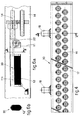
- the plurality of guide tubes 14 positioned side by side cooperates with the device 10 that draws broken threads 111; this device 10 comprises an aspirator/drawing assembly 16 consisting of a box-shaped chamber 17, which is substantially airtight and through which a plurality of conveyor tubes 32 passes from one side to the other side of the chamber 17, each conveyor tube 32 being associated with a corresponding guide tube 14.
- Each conveyor tube 32 is associated with means to aspirate/eject thread, these means consisting of at least one hole that connects at an angle the box-shaped chamber 17 to the inside of the conveyor tube 32.
- conveyor tubes 32 are installed removably in the box-shaped chamber 17 by means of the interposition of seal engagement means 24 consisting of an annular packing of an 0-ring type 25.
- Positioning and clamping means 26 consisting in this case of a flange 27, which cooperates with one sidewall of the box-shaped chamber 17, and of a spacer ring 28 associated with a resilient ring 29 cooperating with the opposite sidewall of the box-shaped chamber 17 are included to ensure proper positioning of the conveyor tubes 32 within the box-shaped chamber 17.
- the box-shaped chamber 17 includes at least one immission duct 18 associated with compression means consisting of an air compressor 19 in this case.
- Each conveyor tube 32 includes in its intermediate segment 20 within the box-shaped chamber 17 at least one injection hole 21 of a small diameter suitably facing in the direction of feed of the thread 11 within the guide tube 14.
- the air under pressure delivered into the box-shaped chamber 17 passes through the injection holes 21 and flows through the conveyor tubes 32 and guide tubes 14, thus creating a negative pressure which attracts the single threads 11 and draws them from the unwinding beam by a pre-set desired length.
- the device 10 When the threads 11 have been unwound by the desired length, the device 10 according to the invention is halted to enable the machine operator to knot the ends of the single threads 11 to the respective thread packages 23.
- the device 10 If one or more threads break during the winding operation, the device 10 according to the invention is actuated automatically and the negative pressure created in the guide tubes 14 attracts the broken thread 111 and draws it by unwinding it from the beam and thus preventing possible problems of entanglement with the other threads 11 being unwound.
- the drawing action ensures drawing of the end of the broken thread 111 with a speed equal to the winding speed so as to keep the broken thread 111 always under a slight tension to prevent it becoming entangled with the other threads 11.
- the air compressor 19 is such as will ensure the maintaining of a negative pressure at about the desired value, which will ensure substantially the drawing of a determined number of broken threads 111 at a pre-set speed for a pre-set time.
- the box-shaped chamber 17 contains a plurality of compartments, with each of which is associated its own immission duct 18 (Fig.4), so as to ensure a negative pressure and therefore a substantially equal drawing action within each conveyor tube 32 and therefore each guide tube 14.
- Each guide tube 14 cooperates at its end with switch means consisting in this case of a deflection plate 33 and switch roller 22 positioned in correspondence with each thread package 23; the switch roller 22 has the task of converting substantially horizontal motion of the thread 11 into substantially vertical motion.
- a take-up chamber 30 is associated with, and located downstream of, each switch roller 22; in this take-up chamber 30 is collected the broken thread 111 drawn by the current of air.
- the take-up chamber 30 has sidewalls consisting of a perforated mesh 12 to enable the drawing air to escape, while the broken thread 111 withheld by the perforated mesh 12 collects within the take-up chamber 30.
- a managing and control unit 31 which manages the winding machine 13 sends a halt signal, which slows the beam and the thread packages 23 according to a pre-set gradient of reduction of speed.
- the air compressor 19 which delivers compressed air into the box-shaped chamber 17 is actuated at the same time.
- shut-off valve means fitted to a tank holding a buffer stock of compressed air fed by the compressor 19 are opened.
- the compressed air passing through the injection holes 21 creates within the conveyor tubes 32 and therefore the guide tubes 14 a negative pressure, which draws the broken thread 111 within the guide tube 14 until the broken thread 111 has been brought to the relative switch roller 22.
- the broken thread 111 is diverted by the deflection plate 33 or else is collected within the take-up chamber 30.
- the machine operator now re-starts the winding machine 13 and beam according to a pre-set gradient of increase of speed until the normal working speed is reached.
Landscapes
- Replacing, Conveying, And Pick-Finding For Filamentary Materials (AREA)
- Tension Adjustment In Filamentary Materials (AREA)
Description
- Fig.1
- is a side diagrammatic view of a form of embodiment of a winding machine equipped with the device according to the invention;
- Fig.2
- is a partial plan view of the machine of Fig.1;
- Fig.3
- is a partial lengthwise view of the machine of Fig.2;
- Fig.4
- shows in an enlarged scale the conveyor assembly of the device according to the invention;
- Fig.5
- shows in a further enlarged scale a cross-section of the conveyor assembly along the line A-A of Fig.4;
- Fig.6a
- shows in an enlarged scale a variant of the detail C of Fig.3;
- Fig.6b
- shows a section along the line B-B of Fig.6a.
Claims (6)
- Device to draw threads (11) and/or broken threads (111) being unwound between a beam and a winding machine (13), the device comprising one guide tube (14) per each thread (11-111), the plurality of guide tubes (14) being in close proximity to each other, and each guide tube (14) including a conveyor tube (32) comprising means to aspirate and eject thread, which can be momentarily actuated and are associated with means that sense broken thread (111) and wherein the means to aspirate/eject thread are associated with an airtight box-shaped chamber (17) characterized in that the device comprises means for a controlled braking and acceleration of the beam and of the winding machine 13, the airtight box-shaped chamber containing a plurality of guide tubes (14) and being put momentarily under pressure, the thread aspiration/ejection means consisting of injection holes (21) which connect at an angle the box-shaped chamber (17) to the inside of each conveyor tube (32).
- Device as in Claim 1, in which each conveyor tube (32) can be replaced by being withdrawn from the box-shaped chamber (17).
- Device as in Claim 1 or 2, in which an assembly holding a buffer stock of thread is included between the beam and the plurality of guide tubes (14).
- Device as in any claim hereinbefore, in which each switch means (22) is associated with a specific deflection plate (33) (Fig.3).
- Device as in any of Claims 1 to 4 inclusive, in which each switch means (22) is associated with a thread take-up chamber (30) (Figs.6).
- Device as in any claim hereinbefore, in which the airtight box-shaped chamber (17) contains a plurality of compartments, with each of which is associated its own duct (18) for immission of air under pressure, the duct (18) being equipped with means to regulate the rate of flow of incoming air.
Applications Claiming Priority (2)
| Application Number | Priority Date | Filing Date | Title |
|---|---|---|---|
| ITUD930098A IT1262124B (en) | 1993-06-07 | 1993-06-07 | DEVICE FOR THE DRAGING OF THE WIRES BETWEEN SUBBIO AND WINDING MACHINE |
| ITUD930098 | 1993-06-07 |
Publications (2)
| Publication Number | Publication Date |
|---|---|
| EP0628506A1 EP0628506A1 (en) | 1994-12-14 |
| EP0628506B1 true EP0628506B1 (en) | 1998-01-21 |
Family
ID=11421301
Family Applications (1)
| Application Number | Title | Priority Date | Filing Date |
|---|---|---|---|
| EP94107941A Expired - Lifetime EP0628506B1 (en) | 1993-06-07 | 1994-05-24 | Device to draw threads between a beam and a winding machine |
Country Status (3)
| Country | Link |
|---|---|
| EP (1) | EP0628506B1 (en) |
| DE (1) | DE69408036T2 (en) |
| IT (1) | IT1262124B (en) |
Family Cites Families (3)
| Publication number | Priority date | Publication date | Assignee | Title |
|---|---|---|---|---|
| US3713572A (en) * | 1971-02-03 | 1973-01-30 | Goldsworthy Eng Inc | Material feeding system |
| US3930602A (en) * | 1974-10-04 | 1976-01-06 | Vorobiev Alexandr Kupriyanovic | Apparatus for transferring threads from the spinning and finishing part of a machine for continuous production of artificial threads to the take-up and winding arrangement thereof |
| IT1242696B (en) * | 1990-12-28 | 1994-05-17 | Cerit Spa | DEVICE FOR REFITTING WIRES BETWEEN SUBBIO AND ROCKING MACHINE. |
-
1993
- 1993-06-07 IT ITUD930098A patent/IT1262124B/en active IP Right Grant
-
1994
- 1994-05-24 DE DE69408036T patent/DE69408036T2/en not_active Expired - Fee Related
- 1994-05-24 EP EP94107941A patent/EP0628506B1/en not_active Expired - Lifetime
Also Published As
| Publication number | Publication date |
|---|---|
| IT1262124B (en) | 1996-06-19 |
| ITUD930098A0 (en) | 1993-06-07 |
| ITUD930098A1 (en) | 1994-12-07 |
| DE69408036T2 (en) | 1998-08-27 |
| DE69408036D1 (en) | 1998-02-26 |
| EP0628506A1 (en) | 1994-12-14 |
Similar Documents
| Publication | Publication Date | Title |
|---|---|---|
| CN103781951B (en) | Apparatus and method for producing knitwear | |
| CN101868570B (en) | Method and device for manufacturing knitwear | |
| US20080283655A1 (en) | Method and device for operating a winding device of a textile machine producing cross-wound bobbins | |
| US4944145A (en) | Spinning machine for producing feeding packages for twisting | |
| CN101177220B (en) | Method for operating winding head of textile machine for preparing cross-wound bobbin | |
| GB1486161A (en) | Method and apparatus for restarting spinning when a break occurs in an open-end spinning machine | |
| US4163357A (en) | Apparatus for cable-twisting two yarns | |
| US3902644A (en) | Apparatus for the treatment of yarn | |
| US2800762A (en) | Apparatus for making yarn packages | |
| US4389837A (en) | Ply yarn spinning assembly | |
| US5044150A (en) | Arrangement for producing packages used as feeding packages for twisting | |
| US4484435A (en) | Method and device for the production of textile fibre yarns | |
| US4958486A (en) | Process and an arrangement for piecing an air-spun yarn | |
| US5163279A (en) | Arrangement for producing feeding packages for a twisting operation | |
| DE102005010534A1 (en) | Weft feeder for weaving machines, in particular rapier weaving machines | |
| EP0628506A1 (en) | Device to draw threads between a beam and a winding machine | |
| JP2019214476A (en) | Method and device of affecting winding condition of ring spinning cop | |
| US3750922A (en) | Aspirator | |
| US4761946A (en) | Arrangement for the prestrengthening of thread components to be twisted together | |
| US20250042690A1 (en) | Thread-splicing device for a workstation of a textile machine producing cross-wound bobbins | |
| EP0492505B1 (en) | Device to piece up threads or yarns between a beam and a winding machine | |
| CZ281430B6 (en) | Process and apparatus for winding thread on to conical bobbins or tubes | |
| US5205118A (en) | Process and an arrangement for exchanging spools and packages at an individual spinning unit of a spinning machine | |
| US5161749A (en) | Device for correcting the variation in tension of the thread as it unwinds in a spooler | |
| CN116791248A (en) | Automatic splicing device and method for fabric ring spinning machine |
Legal Events
| Date | Code | Title | Description |
|---|---|---|---|
| PUAI | Public reference made under article 153(3) epc to a published international application that has entered the european phase |
Free format text: ORIGINAL CODE: 0009012 |
|
| AK | Designated contracting states |
Kind code of ref document: A1 Designated state(s): CH DE ES FR IT LI |
|
| 17P | Request for examination filed |
Effective date: 19950526 |
|
| GRAG | Despatch of communication of intention to grant |
Free format text: ORIGINAL CODE: EPIDOS AGRA |
|
| 17Q | First examination report despatched |
Effective date: 19970402 |
|
| GRAG | Despatch of communication of intention to grant |
Free format text: ORIGINAL CODE: EPIDOS AGRA |
|
| GRAH | Despatch of communication of intention to grant a patent |
Free format text: ORIGINAL CODE: EPIDOS IGRA |
|
| GRAH | Despatch of communication of intention to grant a patent |
Free format text: ORIGINAL CODE: EPIDOS IGRA |
|
| GRAA | (expected) grant |
Free format text: ORIGINAL CODE: 0009210 |
|
| ITF | It: translation for a ep patent filed | ||
| RAP1 | Party data changed (applicant data changed or rights of an application transferred) |
Owner name: JAEGGLI S.P.A. |
|
| AK | Designated contracting states |
Kind code of ref document: B1 Designated state(s): CH DE ES FR IT LI |
|
| PG25 | Lapsed in a contracting state [announced via postgrant information from national office to epo] |
Ref country code: FR Free format text: LAPSE BECAUSE OF FAILURE TO SUBMIT A TRANSLATION OF THE DESCRIPTION OR TO PAY THE FEE WITHIN THE PRESCRIBED TIME-LIMIT Effective date: 19980121 Ref country code: ES Free format text: THE PATENT HAS BEEN ANNULLED BY A DECISION OF A NATIONAL AUTHORITY Effective date: 19980121 |
|
| REG | Reference to a national code |
Ref country code: CH Ref legal event code: NV Representative=s name: R. A. EGLI & CO. PATENTANWAELTE Ref country code: CH Ref legal event code: EP |
|
| REF | Corresponds to: |
Ref document number: 69408036 Country of ref document: DE Date of ref document: 19980226 |
|
| EN | Fr: translation not filed | ||
| PLBE | No opposition filed within time limit |
Free format text: ORIGINAL CODE: 0009261 |
|
| STAA | Information on the status of an ep patent application or granted ep patent |
Free format text: STATUS: NO OPPOSITION FILED WITHIN TIME LIMIT |
|
| 26N | No opposition filed | ||
| REG | Reference to a national code |
Ref country code: CH Ref legal event code: PUE Owner name: JAEGGLI S.P.A. TRANSFER- REGGIANI MACCHINE S.P.A. |
|
| PG25 | Lapsed in a contracting state [announced via postgrant information from national office to epo] |
Ref country code: IT Free format text: LAPSE BECAUSE OF NON-PAYMENT OF DUE FEES;WARNING: LAPSES OF ITALIAN PATENTS WITH EFFECTIVE DATE BEFORE 2007 MAY HAVE OCCURRED AT ANY TIME BEFORE 2007. THE CORRECT EFFECTIVE DATE MAY BE DIFFERENT FROM THE ONE RECORDED. Effective date: 20050524 |
|
| PGFP | Annual fee paid to national office [announced via postgrant information from national office to epo] |
Ref country code: CH Payment date: 20070615 Year of fee payment: 14 |
|
| PGFP | Annual fee paid to national office [announced via postgrant information from national office to epo] |
Ref country code: DE Payment date: 20070622 Year of fee payment: 14 |
|
| REG | Reference to a national code |
Ref country code: CH Ref legal event code: PL |
|
| PG25 | Lapsed in a contracting state [announced via postgrant information from national office to epo] |
Ref country code: LI Free format text: LAPSE BECAUSE OF NON-PAYMENT OF DUE FEES Effective date: 20080531 Ref country code: CH Free format text: LAPSE BECAUSE OF NON-PAYMENT OF DUE FEES Effective date: 20080531 |
|
| PG25 | Lapsed in a contracting state [announced via postgrant information from national office to epo] |
Ref country code: DE Free format text: LAPSE BECAUSE OF NON-PAYMENT OF DUE FEES Effective date: 20081202 |
|
| PGRI | Patent reinstated in contracting state [announced from national office to epo] |
Ref country code: IT Effective date: 20090501 |
|
| PGFP | Annual fee paid to national office [announced via postgrant information from national office to epo] |
Ref country code: IT Payment date: 20070619 Year of fee payment: 14 |
|
| PGRI | Patent reinstated in contracting state [announced from national office to epo] |
Ref country code: IT Effective date: 20090501 |