EP0628339A1 - Method for extraction of undesirable substances in a gas - Google Patents
Method for extraction of undesirable substances in a gas Download PDFInfo
- Publication number
- EP0628339A1 EP0628339A1 EP94109124A EP94109124A EP0628339A1 EP 0628339 A1 EP0628339 A1 EP 0628339A1 EP 94109124 A EP94109124 A EP 94109124A EP 94109124 A EP94109124 A EP 94109124A EP 0628339 A1 EP0628339 A1 EP 0628339A1
- Authority
- EP
- European Patent Office
- Prior art keywords
- gas
- metal
- compounds
- react
- process step
- Prior art date
- Legal status (The legal status is an assumption and is not a legal conclusion. Google has not performed a legal analysis and makes no representation as to the accuracy of the status listed.)
- Granted
Links
Images




Classifications
-
- C—CHEMISTRY; METALLURGY
- C10—PETROLEUM, GAS OR COKE INDUSTRIES; TECHNICAL GASES CONTAINING CARBON MONOXIDE; FUELS; LUBRICANTS; PEAT
- C10L—FUELS NOT OTHERWISE PROVIDED FOR; NATURAL GAS; SYNTHETIC NATURAL GAS OBTAINED BY PROCESSES NOT COVERED BY SUBCLASSES C10G OR C10K; LIQUIFIED PETROLEUM GAS; USE OF ADDITIVES TO FUELS OR FIRES; FIRE-LIGHTERS
- C10L3/00—Gaseous fuels; Natural gas; Synthetic natural gas obtained by processes not covered by subclass C10G, C10K; Liquefied petroleum gas
- C10L3/06—Natural gas; Synthetic natural gas obtained by processes not covered by C10G, C10K3/02 or C10K3/04
- C10L3/10—Working-up natural gas or synthetic natural gas
-
- B—PERFORMING OPERATIONS; TRANSPORTING
- B01—PHYSICAL OR CHEMICAL PROCESSES OR APPARATUS IN GENERAL
- B01D—SEPARATION
- B01D53/00—Separation of gases or vapours; Recovering vapours of volatile solvents from gases; Chemical or biological purification of waste gases, e.g. engine exhaust gases, smoke, fumes, flue gases, aerosols
- B01D53/34—Chemical or biological purification of waste gases
- B01D53/46—Removing components of defined structure
- B01D53/48—Sulfur compounds
- B01D53/52—Hydrogen sulfide
-
- B—PERFORMING OPERATIONS; TRANSPORTING
- B01—PHYSICAL OR CHEMICAL PROCESSES OR APPARATUS IN GENERAL
- B01D—SEPARATION
- B01D53/00—Separation of gases or vapours; Recovering vapours of volatile solvents from gases; Chemical or biological purification of waste gases, e.g. engine exhaust gases, smoke, fumes, flue gases, aerosols
- B01D53/34—Chemical or biological purification of waste gases
- B01D53/46—Removing components of defined structure
- B01D53/54—Nitrogen compounds
- B01D53/58—Ammonia
-
- B—PERFORMING OPERATIONS; TRANSPORTING
- B01—PHYSICAL OR CHEMICAL PROCESSES OR APPARATUS IN GENERAL
- B01D—SEPARATION
- B01D53/00—Separation of gases or vapours; Recovering vapours of volatile solvents from gases; Chemical or biological purification of waste gases, e.g. engine exhaust gases, smoke, fumes, flue gases, aerosols
- B01D53/34—Chemical or biological purification of waste gases
- B01D53/46—Removing components of defined structure
- B01D53/62—Carbon oxides
-
- B—PERFORMING OPERATIONS; TRANSPORTING
- B01—PHYSICAL OR CHEMICAL PROCESSES OR APPARATUS IN GENERAL
- B01D—SEPARATION
- B01D53/00—Separation of gases or vapours; Recovering vapours of volatile solvents from gases; Chemical or biological purification of waste gases, e.g. engine exhaust gases, smoke, fumes, flue gases, aerosols
- B01D53/34—Chemical or biological purification of waste gases
- B01D53/74—General processes for purification of waste gases; Apparatus or devices specially adapted therefor
- B01D53/75—Multi-step processes
-
- Y—GENERAL TAGGING OF NEW TECHNOLOGICAL DEVELOPMENTS; GENERAL TAGGING OF CROSS-SECTIONAL TECHNOLOGIES SPANNING OVER SEVERAL SECTIONS OF THE IPC; TECHNICAL SUBJECTS COVERED BY FORMER USPC CROSS-REFERENCE ART COLLECTIONS [XRACs] AND DIGESTS
- Y02—TECHNOLOGIES OR APPLICATIONS FOR MITIGATION OR ADAPTATION AGAINST CLIMATE CHANGE
- Y02C—CAPTURE, STORAGE, SEQUESTRATION OR DISPOSAL OF GREENHOUSE GASES [GHG]
- Y02C20/00—Capture or disposal of greenhouse gases
- Y02C20/40—Capture or disposal of greenhouse gases of CO2
-
- Y—GENERAL TAGGING OF NEW TECHNOLOGICAL DEVELOPMENTS; GENERAL TAGGING OF CROSS-SECTIONAL TECHNOLOGIES SPANNING OVER SEVERAL SECTIONS OF THE IPC; TECHNICAL SUBJECTS COVERED BY FORMER USPC CROSS-REFERENCE ART COLLECTIONS [XRACs] AND DIGESTS
- Y02—TECHNOLOGIES OR APPLICATIONS FOR MITIGATION OR ADAPTATION AGAINST CLIMATE CHANGE
- Y02P—CLIMATE CHANGE MITIGATION TECHNOLOGIES IN THE PRODUCTION OR PROCESSING OF GOODS
- Y02P20/00—Technologies relating to chemical industry
- Y02P20/151—Reduction of greenhouse gas [GHG] emissions, e.g. CO2
Definitions
- the present invention relates to a method of separating undesirable compounds, primarily carbon dioxide, sulphurous and nitrogen compounds, from a gas, including atmospheric air.
- DE patent 424,596-A1 uses low concentrations of formalin which, combined with said metallic salts, shifts the balance of the ammonium carbonate in the manure on one hand towards ammonium chloride and on the other hand towards calcium- or magnesium carbonate , both of which are precipitated, and the ammonia is bound in an ammonium form which is free of smell and no longer volatile.
- the amount of formalin binds ammonia as a water-soluble product NH2CH2OH analogously with DE 3,412,581 A1.
- GB patents 673,187 and 879,112 do not describe a regenerating method of removing hydrogen sulphide, but rather use an iron(II)sulphate in an alcaline solution for the formation of iron(III).
- DE patent 1,050,013 and US patent 2,641,526 both use a ferric oxy compound which may be regenerated by means of adding air, whereby sulphur is precipitated simultaneously.
- This object is achieved by a method which is characterized in that the undisrable compounds of the gas are transformed into end products, preferably into sulphur, precipitate fertilizers and metallic hydrogen carbonates by treating the gas in at least one process step wherein the undesirable compounds in the gas are caused to react with aqueous solutions of chemical reaction means, catalysts and surface-active substances during formation of the end products.
- ammonia or other nitrogen compounds present e.g. in animal manure, waste water or other highly polluted liquids by performing a so-called ammonium stripping followed by the use of the method according to the present invention.
- ammonia together with other volative gases, may be converted into useful fertilizers in such a manner that the ammoinium evaporation is completely eliminated.
- the resulting precipitate fertilizers are particularly valuable compared to ordinary water-soluble fertilizers which are more or less liable to be washed out.
- the method is particularly useful for biogas since today there is no simple and economical way of purifying biogas so that one obtains the quality of natural gas, i.e. the biogas being purified of mercaptans, hydrogen sulphide, amines, ammonia and carbon dioxide so that the remaining product will be pure methane.
- the known methods of purifying biogas all operate primarily with physical parametres such as changing pressure and temperature, which may, however, be followed by a subsequent chemical treatment for purification and seperation of the condensed products, such as described in GB patents 692,804 and 734,577.
- Fig. 1 shows a flow diagram of the method according to the invention.
- the diagram comprises a first, second, third and fourth process step 1, 2, 3 and 4.
- the diagram comprises two additional process steps 5 and 6 wherein end products are extracted.
- the diagram also comprises a seventh process step 7 wherein the gas may be burned, an eighth process step 8 wherein waste gas is dehydrated, and a nineth process step 9 comprising an oven.
- each of the process steps 1, 2, 3, 4 and 6 there is provided a stirrer and a strainer or a filter for distribution of the substances added in the process steps.
- a heat exchanger is provided so that it is possible to add or remove heat from the process.
- the process steps are connected with each other as indicated by lines between the individual steps. Whether the lines are bold or thin depends on whether the gas is treated in all or just a few process steps. Valves between the individual process steps are illustrated by circles on the lines.
- the gas contains nitrogen compounds R1R2R3 and sulphurous coumpunds, SR1R2.
- the nitrogen and sulphurous may be e.g. ammonia, NH3, respectively hydrogen sulphide, H2S, which two substances will be used in the following as a basis for the description of the individual process steps.
- the gas is led through a valve to the first process step containing an aqueous solution of either an aldehyde, a ketone, organic acids or acid chlorides, phosphate ions, metallic ions or an acid, e.g. phosphoric acid, H3PO4, or a mixture of these substances.
- an aqueous solution of either an aldehyde, a ketone, organic acids or acid chlorides, phosphate ions, metallic ions or an acid, e.g. phosphoric acid, H3PO4, or a mixture of these substances.
- the aqueous solution used will be a solution of formaldehyde, H2CO.
- the gas is bubbled through the aqueous solution while the latter is being stirred.
- Hexamethylene tetramine, C6H12N4, and trithio formaldehyde, C3H6S3, are transferred to process step 5.
- the aqueous reaction solution is precipitated at low-temperature heating and under reduced pressure. Small amounts of thio compounds are removed through reaction with formalin. If one of the radicals in SR1R2 is constituted by anything but hydrogen, H, the following reaction will take place between the sulphurous compound and the aqueous solution of formaldehyde: R1SH + H2CO --> R1SCH2OH or (R1S)2CHOH
- Process step 4 contains an aqueous solution of a metallic salt, preferably Fe2SO4(NO)2 whereby metallic nitrogen oxide salt is formed in a chemical process. This salt may be heated and recirculated.
- a metallic salt preferably Fe2SO4(NO)2 whereby metallic nitrogen oxide salt is formed in a chemical process. This salt may be heated and recirculated.
- Fig. 2 shows a second flow of a process according to the invention.
- the gas has a high content of sulphurous compounds, SR1R2, and carbon dioxide, CO2.
- the contents of nitrogen compounds, NR1R2R3, is insignificantly small.
- H2S will be used as a basis for the sulphurous compound.
- the gas is firstly treated in process step 2. If nitrogen compounds are present in the gas, it must first be treated in process step 1 in order to remove these compounds which would otherwise accumulate in process step 2.
- Process step 2 contains an aqueous solution of ferric oxyhydroxyde, FeO(OH), and the gas containing H2S will react with ferric oxyhydroxyde, resulting in the following reactions: 3 H2S + 2 Fe3+ + 3 OH ⁇ --> Fe2S3 + 3 H+ + 3 H2O 2 Fe2S3 + 3 O2 + 2 H2O --> 4 FeO(OH) + 6 S
- the precipitated ferric sulphide, Fe2S3, is led to process step 6 where atmospheric air is bubbled under stirring whereby ferric sulphide is oxidized into ferric oxyhydroxyde, FeO(OH), during liberation of free sulphur, S, as stated in the second equation.
- the ferric oxyhydroxyde is recycled to process step 2 and the process is repeated.
- pH is adjusted by adding suitable chemical means. pH should preferably be between 5 and 8.
- the gas contains nigrogen compounds, NR1R2R3, e.g. ammonia NH3, the ammonia will react with the ferric oxyhydroxyde, FeO(OH), resulting in the following reactions: Fe3+ + 3 NH3 + 3 H2O --> Fe(OH)3 + 3 NH + 4 Fe(OH)3 --> FeO(OH) + H2O
- the gas is now free of undesirable, malodorous and poisonous substances and may be led to process step 3 for removal of CO2. If it is not desired to have CO2 removed, the gas is led directly to process step 7 for burning, alternatively directly to the recipient.
- Removal of CO2 in process step 3 is accomplished by bubbling the gas while stirring with a chemically active solution of a suitable precipitation means, which is added to the process continuously.
- a chemically active solution of a suitable precipitation means which is added to the process continuously.
- process step 3 contains a metallic chloride as chemically active means, it will be consumed by bubbling with CO2 during formation of metallic hydrogen carbonate, metal(HCO3) y , which is precipitated and removed from the process.
- the following reactions will happen, capital M signifying a metal: MCl y + y CO2 + y NH3 + y H2O --> M(HCO3) y + y NH4Cl M(OH) y + y NH4Cl --> MCl y + y NH3 + y H2O
- ammonium chloride NH4Cl
- a base such as metallic hydroxyde, M(OH) y
- ammonia and metallic carbonate may be used for adjusting pH in process 2.
- Removal of carbon dioxide, CO2 is a cyclical process and requires no continuous addition of ammonia, NH3.
- the gas After the gas has been treated in process step 2 and process step 3, it is free of sulphurous compounds and of CO2. Afterwards the gas may optionally be led to process step 7 for burning. After burning the waste gas will only contain carbon dioxide, CO2, and water, H2O, as the acid oxides have been removed from the gas prior to the burning.
- the process may be performed with many different types of biological fuel, e.g. straw. If the waste gas contains compounds comprising NO X , e.g. caused by a high burning temperature, these may be removed by first dehydrating the gas in process step 8 and then leading it to one of the following processes:
- Fig. 3 shows another flow diagram for a method according to the invention.
- the gas contains a large share of nitrogen compounds, NR1R2R3 and a low content of sulphurous compounds, SR1R2.
- the gas is led to process step 1 where the nitrogen compounds are removed by reaction with metal(II)hydrogen phosphate, MHPO4, whereby metal(II)ammonium phosphate, NH4MPO4, is formed.
- the mol relationship between ammonia, metal(II) and phosphate may be 1:1:1, 2:1:2 or 4:1:2, respectively.
- the formed metal(II)ammonium phosphate may, by heating or by chemical treatment, be caused to liberate ammonia, NH3, which may be used in process step 3 for the removal of carbon dioxide, CO2. Excessive metal(II)hydrogen phosphate may be recirculated to process step 1 for repeated reaction with ammonia or amines.
- process step 2 contains metal(III)oxyhydroxide, MO(OH).
- MO(OH) metal(III)oxyhydroxide
- SR1R2 metal(III)oxyhydroxide
- M2S3 metal(III)sulphide
- Fe2S3 may be reformed into ferric oxyhydroxide, FeO(OH), and free sulphur, S, during the following reactions: 3 H2S + 2 Fe3+ + 3 OH ⁇ --> Fe2S3 + 3 H+ + 3 H2O 2 Fe2S3 + 3 O2 + 2 H2O --> 4 FeO(OH) + 6 S
- the sulphur is removed from the surface of the aqueous phase or by means of centrifugation. After regeneration, the water containing ferric oxyhydroxide, FeO(OH), is led back to process step 2, whereupon the process is repeated.
- the gas is led on to process step 3 for removal of CO2 as described in the text of Fig. 2. If removal of CO2 is not desired, the gas is led directly to process step 7, alternatively directly to the recipient.
- the process step contains an aqueous solution of formaldehyde, H2CO, whereby the contents of ammonia, NH3, and hydrogen sulphide, H2S, in the gas are removed.
- the composition of the gas prior to treatment is as follows:
- composition of the gas after treatment is as follows:
- biogas is not led through process step 2 as H2S has been removed by 99.99%. Whether carbon dioxide CO2 is removed, depends on whether it is profitable in respect of the difference in sales price existing for biogas with and without carbon dioxide, respectively.
- Waste water from a fish plant is stripped, e.g. by ventilation, whereby the volatile compounds are driven off the waste water.
- the resulting gas with the volatile compounds is led to process step 2 where the gas is bubbled through a solution containing ferric oxyhydroxyde, FeO(OH).
- ferric sulphides, Fe2S3, are formed and precipitated. If process step 2 takes place at a temperature of approx. 50°C, and if atmospheric air is added simultaneously, the nitrogen compounds will be driven off and they are subsequently led from process step 2 to process step 1.
- Phosphoric acid, H3PO4, is added in process step 1.
- process step 1 is saturated with the nitrogen compounds, calcium carbonate, CaCO3, is added for adjustment of pH to approx. 7.5. Then a phosphate compound will be precipitated, having the following composition: (NR1R2R3)2Ca(HPO4)2, 2 H2O
- N, P and Ca, respectively, in the precipitated substances confirms the structure.
- a measure of N and P prior to the addition of calcium carbonate is necessary in order to establish the correct stoichiometric relationship between N and P and calcium carbonate, respectively.
- Other metallic ions than calcium e.g. potassium K or magnesium Mg, may be added; it is merely a question of price and of the micro nutrient the finished fertilizer is supposed to contain. If for example magnesium carbonate is used, there is a possibility of a mixture of precipitated metallic phosphates: I) (NR1R2R3H)2Mg(HPO4)2, x H2O II) NR1R2R3H2MgPO4, 1-6 H2O
- the waste water is free of malodorous substances, and an analysis shows a reduction of NR1R2R3 and SR1R2 of between 98% and 99.9%.
- Manure either degased in order to reduce excess ammonia or not, is subjected to ammonia stripping. After the stripping, the manure is free of most of the nitrogen compounds and therefore, usually on exemption, it may be spread on suitable areas.
- the stripped ammonia is of approximately 30%, which is an increase of the concentration from approximately 0.4% in the raw manure.
- the stripping is preferably accomplished by adding metalphosphate to the manure whereby metalammonium phosphate is precipitated.
- the precipitated metalammonium phosphate is subjected to a chemical or thermal treatment by addition of base or by heating, whereby the ammonia is liberated in a gaseous form.
- metalphosphate ions are precipitated which may be recirculated in the stripping process, or which may be reused in process step 1 according to the present invention.
- the stripped ammonia is treated by the method according to the invention.
- a crystalline substance e.g. in the form of C6H12N4, (NH4)2M(HPO4)2 or NH4MPO4, is formed. This leaves a remaining concentration of the stripped 30% ammonia of 0.1 - 10 ppm.
- fertilizer precipitate depends on local conditions, including the possibility of buying phosphor. If the option of buying phosphor is available, ammonia from the manure stripping is treated in process step 1 with phosphate by addition of acid in the form of phosphorous acid or by addition of other phosphate substances such as metal(II)hydrophosphate. If there is excess phosphor in the area where the fertilizer precipitate is to be spread, one may add formaldehyde in process step 1 so that a non-phosphate precipitate is precipitated.
- the ammonium chloride solution may be led to process 1 and is processed in process step 2 or as non-phosphate fertilizer precipitate.
- a mixture of divalent metallic ions may advantageously be used for precipitation of amines such as ammonia and ammonium ions as considerably lower concentrations of nitrogen and phosphor will remain at a lower pH than if the metal alone were present in the solution.
- the waste gas may contain acid oxides such as NO x , which may be removed as described in Fig. 2.
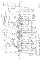
- Fig. 4 illustrates a first embodiment of a process plant for use by the method according to the invention.
- the reaction speed is increased approximately 10 times by adding sodium hydroxide.
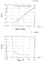
- the change of the surface tension increases the speed approximately 3 times, see Fig. 6.
- the result has appeared by keeping the pressure, the temperature and the rate of flow constant through a chemically active solution.
- the biogas may contain traces of ammonia small amounts of NH2CH2OH and (CH2)6N4 may be formed when the biogas is bubbled through the chemically active solution.
- An increase of the hydroxide ion concentration accelerates the process further and reduces the solubility of methane in the formalin, and restrains simultaneously the forming of (CH2)6N4.
- Fig. 7 shows the surface tension as a function of the concentration of the surface-active agent.
- the biogas is at the bottom pumped into a tank A* and the gas is dispersed in small bubbles through a diffuser in such a way that the surface of the gas is as large as possible. Simultaneously with the biogas-bubbles upward direction, these are met by a downward water current consisting of the chemical active solution. By using said procedure the contact time of the biogas with the chemical active solution is increased.
- tank A* When the concentration of formalin in tank A* is below a specified level a valve is closed and the biogas is led to tank A.
- the tank A contains the same chemical active solution as tank A* and the cleaning process is continued in tank A as in tank A*.
- the solution in tank A* with the formed cyclic trimer (C3H6S3) is pumped into the reaction tank A2.
- the tank A3 contains the same dissolved chemicals which are/were present in tank A*.
- the purpose of pumping liquid from tank A3 into tank A*, so that the latter is completely full, serves as certainty that all the biogas is removed from A* before the resultant liquid is transferred to A2 during air intake in tank A*. Hereby the danger of explosion is avoided.
- tank A* When the whole amount in tank A* is transferred into tank A2 the latter is heated to a temperature of 55°C and the pressure is reduced to 0.5 atm. of pressure. Water is distilled off to approximately half volume. The remaining part of the liquid containing the cyclic trimer (C3H6S3) is pumped to a strain, where the cyclic trimer (C3H6S3) is separated from the chemical active solution, which is led back into tank A*, where the equivalent amount of formalin is added, corresponding to the cyclic trimer (C3H6S3) removed from the solution. The distillate from A2 is led back into tank A*. A* is now once more ready for biogas cleaning.
- the biogas When the biogas has passed A* and the hydrogen sulphide is removed, the biogas is pumped into tank B* where the gas is pressed through a diffuser to obtain a surface as large as possible.
- the upward bubbles meet a strong counter-current of a chemical active solution, which increases the contact time between the carbon dioxide of the biogas and the solution.
- the aqueous solution consists primarily of ammonia and an inorganic salt where the cation may be mono- or bivalent.
- the anion may be halogen, sulphate or phosphate.
- the speed with which the carbon dioxide may be removed from the biogas is partly dependent on the biogas speed through the solution, the diameter of the biogas bubbles and the speed with which the carbon dioxide reacts with the chemically active solution. Physical parameters such as pressure and temperature obviously also have an influence on the reaction speed.
- Fig. 6 shows the diameters of the bubbles are directly proportional to the surface tension of the chemically active solution. Simultaneously, it is shown that the removal of the carbon dioxide follows the bubble diameter for the biogas, Fig. 8. It means that the reaction speed between the carbon dioxide and the chemically active solution is increased. As shown in Fig. 9 the removal of carbon dioxide is inversely proportional to the surface tension, which is of great importance for the biogas flow through the plant and accordingly for the size of the plant.
- Fig. 9 is produced in such a way that 100% CO2 represents a certain biogas flow through the chemically active solution where the carbon dioxide of the biogas is removed.
- the biogas flow is increased in such a way that the carbon dioxide of the biogas just is removed. 200% CO2 are equivalent to a doubling of the biogas flow.
- the tanks B* and B2* work at the same time, i.e. after the biogas has left B* it is pumped into B2* in which the same process is repeated as in B*, as it is the same chemically active solutions.
- Two tanks are used of practical reasons.
- the chemically active solution in e.g. tank B* is consumed (i.e. the carbon dioxide is precipitated as a sparingly soluble carbonate)
- the whole content of the tank is pumped to a strain where the sparingly soluble carbonate is removed and the liquid is led back to tank B* for regeneration and adjusting by adding new chemicals so that the process may be repeated.
- Tank B2* undergoes the same procedure as tank B*.
- Tank B* is processed more often than tank B2* as the majority of the carbon dioxide is removed by passage of the first tank B*.
- Tank B3 pumps water into tank B* as well as into tank B2* in order to prevent forming of methane pockets in the tanks before the pumping out of the resulting chemically active liquids for cleaning, regeneration and adjusting. While said cleaning procedure, regeneration and adjusting has taken place for the tanks B* and B2* the biogas is led to the tanks B and B2 for the removal of carbon dioxide.
- these tanks (B and B2) have reacted completely, i.e. the precipitate material is used, they undergo the same procedure as for the tanks B* and B2*.
- a constant measuring of ammonia and carbon dioxide in the tanks B*,-B2*,B and B2 takes care that the concentration in the chemically active solutions all the time are at a maximum, which simultaneously reduces the solubility of the methan in the liquids.
- the sparingly soluble carbonate is regenerated in the heater and is transferred to silo 3 in order to be re-used in the process as a base (metaloxide).
- Silo 1 contains ammonia (alkali) and silo 2 metalsalt, e.g. CaCl2, MgCl2, NaCl etc.
- CaCl2 is used for this example CaCl2 is used.
- the Biogas is now free of hydrogen sulphide, ammonia and carbon dioxide, but because of the volatility of ammonia the methane contains small amounts of ammonia from the tanks (B*,B,B2* and B2) which are removed in tank C.
- Tank C contains phosphoric acid by which the ammonia is catched.
- a sparingly soluble double salt (NH4)2Ca(HPO4)2,H2O is precipitated, at a pH value between 5.2 and 8.0.
- process step C may run continuously with a constant removal of the precipitated diammonium-calcium-diphosphate.
- diammonium-calcium-diphosphate has great interest, as the crops grow surprisingly better than a corresponding fertilizer with the same content of nitrogen and phosphor in percentages. If magnesium oxide had been used as a base, the corresponding diammonium-magnesium-diphosphate would have been precipitated with the same interesting fertilizing effect as described above. Mixing of the bases is also possible as the fertilizer product thereby changes the water-solubility.
- the biogas is now converted into pure methane and may be led on to a natural gas system. All process steps for the whole system are measured and automatically controlled by PLC. The plant is controlled on the basis of the following measurings: hydrogen sulphide, carbon dioxide, ammonia, water, nitrogen and methane and the pH value, conductivity and the surface tension.
- the precipitated products from the tanks A*, A and C are used as sulphurous, nitrogenous and phosphorous fertilizer and are produced as precipitates.
- Fig. 5 shows a second embodiment where the content of A* and A is replaced with ferrioxysulphate or ferrioxyhydroxide in stead of formalin.
- the A* and A solution also consists of surface-active substances.
- the surface-active substances are primarily non-ionic, non-foaming and are primarily chosen among the surface-active substances containing silicones and fluorine, as only extremely small amounts are necessary in order to obtain the desired effect.
- the advantage of using a tervalent oxysalt, as e.g. ferrioxysulphate and ferrioxyhydroxide is that they can be regenerated again after having reacted during precipitation with the hydrogen sulphide of the biogas.
- iron(III)chloride in an acid environment wherein iron(III) is converted into iron(II) and free sulphur. Iron(II) may then be regenerated into acid iron(III).
- Said method aims at using the acid oxide in the biogas as a buffer in connection with the precipitation of hydrogen sulphide in an acid environment according to the following: 4Fe3 ⁇ + 2H2S --> Fe2+ + 2S + 4H+
- a non-ionic silicone-containing surface-active substance has been added, which is inactive with regard to iron(II)/(III).
- the purpose of the surface-active substance is as earlier described.
- the biogas is pumped into tank A* in which the above described reaction takes place (1A).
- the content is pumped from A* to a strain or separator where the sulphur is removed.
- the resulting solution which is now free from sulphur is pumped into tank A2.
- tank A2 atmospheric air is pumped through the diffuser and the regeneration takes place after reaction (2A). After the regeneration the content in A2 is pumped back into tank A*.
Landscapes
- Chemical & Material Sciences (AREA)
- Engineering & Computer Science (AREA)
- Oil, Petroleum & Natural Gas (AREA)
- Chemical Kinetics & Catalysis (AREA)
- General Chemical & Material Sciences (AREA)
- Environmental & Geological Engineering (AREA)
- Biomedical Technology (AREA)
- Analytical Chemistry (AREA)
- Health & Medical Sciences (AREA)
- Organic Chemistry (AREA)
- Gas Separation By Absorption (AREA)
- Treating Waste Gases (AREA)
- Medicines Containing Plant Substances (AREA)
- Medicines Containing Material From Animals Or Micro-Organisms (AREA)
- Fertilizers (AREA)
- Sampling And Sample Adjustment (AREA)
Abstract
Description
- The present invention relates to a method of separating undesirable compounds, primarily carbon dioxide, sulphurous and nitrogen compounds, from a gas, including atmospheric air.
- Various methods wherein a purification of gases is performed are known from SU 814,414, SU 768,440 and JP 54,100,975. All of these publications relate to removal of H₂S during formation of ferric hydroxide. Further methods are known for removal of mercaptans and for removal of NOx, e.g. with the use of active carbon.
- The disadvantage of the known methods is that they do not to a sufficient extent permit the removal of many of the undesirable substances comprised in gases of the above-mentioned kind. Besides, many of the processes used in the prior art are very complicated and unsuitable for use in situ, e.g. on a farm. Finally, the prior art does not show how substances that are removed may be reused.
- Various patents, such as DE 3,412,581-A1 are known wherein formalin is used for various objects and wherein the use of formalin serves to remove ammonia and hydrogen cyanide during formation of (CH₂)₆N₄ and CH₂(OH)CN. While both ammonia and HCN are excellent nucleophile reagents which both react readily with formal in, hydrogen sulphide is a comparatively less ready nucleophile and will, therefore, react very slowly unless a catalyst is present.
- DE patent 424,596-A1 uses low concentrations of formalin which, combined with said metallic salts, shifts the balance of the ammonium carbonate in the manure on one hand towards ammonium chloride and on the other hand towards calcium- or magnesium carbonate , both of which are precipitated, and the ammonia is bound in an ammonium form which is free of smell and no longer volatile. Here the amount of formalin binds ammonia as a water-soluble product NH₂CH₂OH analogously with DE 3,412,581 A1.
- The patents PCT W0 93/006063 and GB 1,538,661 are prior art wherein ammonia is captured in an acid solution during formation of ammonium ions and respective anions, here sulphate and phosphate which are both water-soluble, that means they are not precipitated as precipitates.
- As disclosed in DK patents 17,226 and 19,403, these both use a different regeneration procedure for the trivalent metallic oxyhydroxyde (Fe00H). The precipitated sulphurous compounds are also of a different type.
- GB patents 673,187 and 879,112 do not describe a regenerating method of removing hydrogen sulphide, but rather use an iron(II)sulphate in an alcaline solution for the formation of iron(III). DE patent 1,050,013 and US patent 2,641,526 both use a ferric oxy compound which may be regenerated by means of adding air, whereby sulphur is precipitated simultaneously.
- Thus, it is the object of the present invention to disclose a method which will permit the removal of several of the substances comprised in gases from agriculture, industry, purification plants and others from other contexts, and which will at the same time ensure that the removal of those substances may take place in a simple manner so that the mehtod is not dependent on complicated technical installations, while it is ensured at the same time that the extracted substances may be reused as end products or recirculated in the process.
- This object is achieved by a method which is characterized in that the undisrable compounds of the gas are transformed into end products, preferably into sulphur, precipitate fertilizers and metallic hydrogen carbonates by treating the gas in at least one process step wherein the undesirable compounds in the gas are caused to react with aqueous solutions of chemical reaction means, catalysts and surface-active substances during formation of the end products.
- By this method it now becomes possible, by means of relatively simple chemical processes and with the use of simple reaction means, to remove several of the substances comprised in gases from the above-mentioned contexts. Moreover, the method according to the invention will ensure that most of the substances extracted by removal of the undesired substances may be reused as fertilizers in forestry, horticulture or agriculture or as other end products.
- It will for example be possible to use the ammonia or other nitrogen compounds present e.g. in animal manure, waste water or other highly polluted liquids by performing a so-called ammonium stripping followed by the use of the method according to the present invention. In this manner the ammonia, together with other volative gases, may be converted into useful fertilizers in such a manner that the ammoinium evaporation is completely eliminated. The resulting precipitate fertilizers are particularly valuable compared to ordinary water-soluble fertilizers which are more or less liable to be washed out.
- Furthermore, it will be possible completely to remove hydrogen sulphide or other sulphurous compounds from the treated gas. Many of these substances, like the nitrogen compounds, present environmental risks but they are also undesirable because of noxious smells. The hydrogen sulphide is removed in such a manner, that pure sulphur is extracted which may be reused as raw matter.
- Finally, procedures for use with the method according to the present invention are disclosed wherein it is further possible to remove carbon dioxide, if any. If the gas is burned, it is also possible to remove NOx compounds from the treated gas. Thus, all the poisonous, environmentally detrimental or unpleasant gases present in the gas are decomposed while at the same a considerable part of the substances being removed are precipitated into chemical compounds which may be reused as fertilizers or as raw matter.
- As the content of carbon dioxide in biogas is typically between 30 and 50%, it is very essential that the chemically active solution through which the gas must pass in order to initially remove hydrogen sulphide, does not react with the carbon dioxide of the biogas and also cannot dissolve the methane of the biogas.
- As the amount of carbon dioxide in biogas is large, pH will fall in an aqueous solution and thus interfere with the elimination of H₂S from the biogas. For the preparation of a chemically active solution one may use e.g. strongly polar organic compounds such as aldehydes and ketones in combination with the adding of inorganic ions as these and will prevent the methane from dissolving in the organic compounds. Applicable cations may be natrium, calium, magnesium, manganese, iron etc. The anion may be sulphate, halogenide, oxide, hydroxide etc.
- With the method according to the invention it is easy and fast to change the contencts of individual reactants in the different process steps depending on the composition of the gas to be treated. Furthermore, removal of the chemical compounds contained in the gas may in several cases be performed in a random order.
- The method is particularly useful for biogas since today there is no simple and economical way of purifying biogas so that one obtains the quality of natural gas, i.e. the biogas being purified of mercaptans, hydrogen sulphide, amines, ammonia and carbon dioxide so that the remaining product will be pure methane. The known methods of purifying biogas all operate primarily with physical parametres such as changing pressure and temperature, which may, however, be followed by a subsequent chemical treatment for purification and seperation of the condensed products, such as described in GB patents 692,804 and 734,577.
- The invention will now be described in further detail with reference to the accompanying drawing, wherein
- fig. 1
- shows a flow diagram for a process passage according to the invention
- fig. 2
- shows a second flow diagram of a process passage according to the invention,
- fig. 3
- shows an additional flow diagram of a process passage according to the invention,
- fig. 4
- shows a first embodiment of a process plant for use by the method according to the invention
- fig. 5
- shows a second embodiment of a process plant for use by the method according to the invention
- fig. 6
- shows the surface tension as a function of relative bubble diameter,
- fig. 7
- shows the surface tension as a function of the concentration of a surface-active means,
- fig. 8
- shows the bubble diameter as a function of surface tension and carbon dioxide removal as a function of surface tension, and
- fig. 9
- shows surface tension as a function of the concentration of a surface-active means.
- Fig. 1 shows a flow diagram of the method according to the invention. The diagram comprises a first, second, third and
fourth process step additional process steps seventh process step 7 wherein the gas may be burned, aneighth process step 8 wherein waste gas is dehydrated, and anineth process step 9 comprising an oven. - In each of the
process steps - In fig. 1 the gas is treated in the following process steps as illustrated by the shown flow diagram.
- The gas contains nitrogen compounds R₁R₂R₃ and sulphurous coumpunds, SR₁R₂. The nitrogen and sulphurous may be e.g. ammonia, NH₃, respectively hydrogen sulphide, H₂S, which two substances will be used in the following as a basis for the description of the individual process steps.
- The gas is led through a valve to the first process step containing an aqueous solution of either an aldehyde, a ketone, organic acids or acid chlorides, phosphate ions, metallic ions or an acid, e.g. phosphoric acid, H₃PO₄, or a mixture of these substances. In the following the basis for the aqueous solution used will be a solution of formaldehyde, H₂CO. The gas is bubbled through the aqueous solution while the latter is being stirred. The gas containing NH₃ and H₂S will react with the formaldehyde, H₂CO, resulting in the reactions:


- Hexamethylene tetramine, C₆H₁₂N₄, and trithio formaldehyde, C₃H₆S₃, are transferred to process
step 5. Here the aqueous reaction solution is precipitated at low-temperature heating and under reduced pressure. Small amounts of thio compounds are removed through reaction with formalin. If one of the radicals in SR₁R₂ is constituted by anything but hydrogen, H, the following reaction will take place between the sulphurous compound and the aqueous solution of formaldehyde:
- Other suitable reaction means for precipitation of stripped amines such as ammonia will be described later. The gas that has been treated in
process step 1 is thus liberated of NH₃ and H₂S and then led directly to processstep 7 where the gas is burned. In this burning NOx compounds may be formed which are led out ofprocess step 7 as part of the waste gas from the burning. If the waste gas contains NOX compounds, a dehydration of the smoke gas is performed initially inprocess step 8 whereupon the waste gas is led toprocess step 4.Process step 4 contains an aqueous solution of a metallic salt, preferably Fe₂SO₄(NO)₂ whereby metallic nitrogen oxide salt is formed in a chemical process. This salt may be heated and recirculated. - Fig. 2 shows a second flow of a process according to the invention. The gas has a high content of sulphurous compounds, SR₁R₂, and carbon dioxide, CO₂. The contents of nitrogen compounds, NR₁R₂R₃, is insignificantly small. In the following H₂S will be used as a basis for the sulphurous compound. The gas is firstly treated in
process step 2. If nitrogen compounds are present in the gas, it must first be treated inprocess step 1 in order to remove these compounds which would otherwise accumulate inprocess step 2.Process step 2 contains an aqueous solution of ferric oxyhydroxyde, FeO(OH), and the gas containing H2S will react with ferric oxyhydroxyde, resulting in the following reactions:

- The precipitated ferric sulphide, Fe₂S₃, is led to
process step 6 where atmospheric air is bubbled under stirring whereby ferric sulphide is oxidized into ferric oxyhydroxyde, FeO(OH), during liberation of free sulphur, S, as stated in the second equation. The ferric oxyhydroxyde is recycled to processstep 2 and the process is repeated. Inprocess step 2 pH is adjusted by adding suitable chemical means. pH should preferably be between 5 and 8. - If, exeptionally, the gas contains nigrogen compounds, NR₁R₂R₃, e.g. ammonia NH₃, the ammonia will react with the ferric oxyhydroxyde, FeO(OH), resulting in the following reactions:


- The gas is now free of undesirable, malodorous and poisonous substances and may be led to
process step 3 for removal of CO₂. If it is not desired to have CO₂ removed, the gas is led directly to processstep 7 for burning, alternatively directly to the recipient. - Removal of CO₂ in
process step 3 is accomplished by bubbling the gas while stirring with a chemically active solution of a suitable precipitation means, which is added to the process continuously. E.g. ifprocess step 3 contains a metallic chloride as chemically active means, it will be consumed by bubbling with CO₂ during formation of metallic hydrogen carbonate, metal(HCO₃)y, which is precipitated and removed from the process. The following reactions will happen, capital M signifying a metal:

- To the formed ammonium chloride, NH₄Cl, is added, as stated in another equation, a base such as metallic hydroxyde, M(OH)y, whereby ammonia and metallic carbonate may be used for adjusting pH in
process 2. Removal of carbon dioxide, CO₂, is a cyclical process and requires no continuous addition of ammonia, NH₃. - After the gas has been treated in
process step 2 andprocess step 3, it is free of sulphurous compounds and of CO₂. Afterwards the gas may optionally be led toprocess step 7 for burning. After burning the waste gas will only contain carbon dioxide, CO₂, and water, H₂O, as the acid oxides have been removed from the gas prior to the burning. The process may be performed with many different types of biological fuel, e.g. straw. If the waste gas contains compounds comprising NOX, e.g. caused by a high burning temperature, these may be removed by first dehydrating the gas inprocess step 8 and then leading it to one of the following processes: - A) The waste gas is led through a filter containing concentrated sulphuric acid, H₂SO₄, and subsequently through an oven,
process step 9, formation FeX₂(s) as chemical reaction means. This will cause the formation of Fe(NO)nX, wherein the X may be any one of the substances SK, Cl, I, SR₁, and wherein n = 1, 2 or 3. If the oven contains e.g. ferric chloride, FeCl₂, a formation of Fe(NO)₃Cl will take place in the oven. - B) If the amount of NOX compounds formed during burning has a very low concentration, the waste gas may be led to
process step 4. Here the waste gas is bubbled during stirring through a solution containing sulphuric acid, H₂SO₄, and ferrous sulphate, FeSO₄. In this manner Fe₂SO₄(NO)₂ and FeSO₄NO are formed. - Fig. 3 shows another flow diagram for a method according to the invention. The gas contains a large share of nitrogen compounds, NR₁R₂R₃ and a low content of sulphurous compounds, SR₁R₂. The gas is led to
process step 1 where the nitrogen compounds are removed by reaction with metal(II)hydrogen phosphate, MHPO₄, whereby metal(II)ammonium phosphate, NH₄MPO₄, is formed. The mol relationship between ammonia, metal(II) and phosphate may be 1:1:1, 2:1:2 or 4:1:2, respectively. - The formed metal(II)ammonium phosphate may, by heating or by chemical treatment, be caused to liberate ammonia, NH₃, which may be used in
process step 3 for the removal of carbon dioxide, CO₂. Excessive metal(II)hydrogen phosphate may be recirculated to processstep 1 for repeated reaction with ammonia or amines. - After having been treated in
process step 1, the gas is led on to processstep 2, which contains metal(III)oxyhydroxide, MO(OH). The contents of sulphurous compounds, SR₁R₂, in the gas will react with the metallic ion during formation of metal(III)sulphide, M₂S₃. In the following, H₂S will be used as a basis for SR₁R₂, ferric oxyhydroxide, FeO(OH) will be used as a basis for metal(III)oxyhydroxide, and Fe₂S₃ will be used as a basis for metallic (III) sulphide. During addition of atmospheric air to processstep 6, Fe₂S₃ may be reformed into ferric oxyhydroxide, FeO(OH), and free sulphur, S, during the following reactions:

- The sulphur is removed from the surface of the aqueous phase or by means of centrifugation. After regeneration, the water containing ferric oxyhydroxide, FeO(OH), is led back to
process step 2, whereupon the process is repeated. - After NR₁R₂R₃ and SR₁R₂ have been removed from the gas, the gas is led on to process
step 3 for removal of CO₂ as described in the text of Fig. 2. If removal of CO₂ is not desired, the gas is led directly to processstep 7, alternatively directly to the recipient. - In the following individual specific tests and their results will be presented, which tests illustrate the effectiveness of the method according to the invention for treatment of gas from various sources.
- 10 litres of biogas are bubbled through an aqueous solution according to
process step 1. The process step contains an aqueous solution of formaldehyde, H₂CO, whereby the contents of ammonia, NH₃, and hydrogen sulphide, H₂S, in the gas are removed. The composition of the gas prior to treatment is as follows: - CH₄:
- 64,4%
- CO₂:
- 35,1%
- NH₃:
- 0,1% 1000 ppm
- H₂S:
- 0,3% 3000 ppm
- During treatment the following reactions take place:


- The composition of the gas after treatment is as follows:
- CH₄:
- 64,7%
- CO₂:
- 4 ppm
- NH₃:
- 0,0004% 4 ppm
- H₂S:
- 0,0002% 2 ppm
-
Analysis of C₆H₁₂N₄: calculated C: 51.43% H: 8.57% N:40.00% S: - analysed C: 51.21% H: - N: 39.94% S: - Analysis of C₃H₆S₃: calculated C: 26.09% H: 4.34% N: - S: 69.57% analysed C: 25.98% H: - N: - S: 69.62% - The biogas is not led through
process step 2 as H₂S has been removed by 99.99%. Whether carbon dioxide CO₂ is removed, depends on whether it is profitable in respect of the difference in sales price existing for biogas with and without carbon dioxide, respectively. - Waste water from a fish plant is stripped, e.g. by ventilation, whereby the volatile compounds are driven off the waste water. The resulting gas with the volatile compounds is led to
process step 2 where the gas is bubbled through a solution containing ferric oxyhydroxyde, FeO(OH). - The contents of nitrogen and sulphurous compounds in the gas prior to treatment are:
- NR₁R₂R₃:
- 2500 ppm
- SR₁R₂:
- 3100 ppm
- As the gas is bubbled in
process step 2, ferric sulphides, Fe₂S₃, are formed and precipitated. Ifprocess step 2 takes place at a temperature of approx. 50°C, and if atmospheric air is added simultaneously, the nitrogen compounds will be driven off and they are subsequently led fromprocess step 2 to processstep 1. Phosphoric acid, H₃PO₄, is added inprocess step 1. Whenprocess step 1 is saturated with the nitrogen compounds, calcium carbonate, CaCO₃, is added for adjustment of pH to approx. 7.5. Then a phosphate compound will be precipitated, having the following composition:
- An analysis of the percentages of N, P and Ca, respectively, in the precipitated substances confirms the structure. A measure of N and P prior to the addition of calcium carbonate is necessary in order to establish the correct stoichiometric relationship between N and P and calcium carbonate, respectively. Other metallic ions than calcium, e.g. potassium K or magnesium Mg, may be added; it is merely a question of price and of the micro nutrient the finished fertilizer is supposed to contain. If for example magnesium carbonate is used, there is a possibility of a mixture of precipitated metallic phosphates:
I) (NR₁R₂R₃H)₂Mg(HPO₄)₂, x H₂O
II) NR₁R₂R₃H₂MgPO₄, 1-6 H₂O
- It is possible to control the process so that only one of the compounds is precipitated. The process wherein I) is precipitated takes place at a lower pH than that of the process wherein II) is precipitated. Moreover, the two processes take place under different stoichiometric conditions. II) is precipitated at 1 mol water of crystallization at a temperature above 75°C. Below that temperaure, 6 mol water of crystallization will be the dominant compound.
- An anlysis of the percentages of N, P and Mg respectively confirm the two structures in the precipitat.
- After having been treated in
process step 2 andprocess step 1, the waste water is free of malodorous substances, and an analysis shows a reduction of NR₁R₂R₃ and SR₁R₂ of between 98% and 99.9%. - Manure, either degased in order to reduce excess ammonia or not, is subjected to ammonia stripping. After the stripping, the manure is free of most of the nitrogen compounds and therefore, usually on exemption, it may be spread on suitable areas. The stripped ammonia is of approximately 30%, which is an increase of the concentration from approximately 0.4% in the raw manure. The stripping is preferably accomplished by adding metalphosphate to the manure whereby metalammonium phosphate is precipitated. The precipitated metalammonium phosphate is subjected to a chemical or thermal treatment by addition of base or by heating, whereby the ammonia is liberated in a gaseous form. By the chemical or thermal treatment metalphosphate ions are precipitated which may be recirculated in the stripping process, or which may be reused in
process step 1 according to the present invention. - The stripped ammonia is treated by the method according to the invention. Hereby a crystalline substance, e.g. in the form of C₆H₁₂N₄, (NH₄)₂M(HPO₄)₂ or NH₄MPO₄, is formed. This leaves a remaining concentration of the stripped 30% ammonia of 0.1 - 10 ppm.
- The choice of fertilizer precipitate depends on local conditions, including the possibility of buying phosphor. If the option of buying phosphor is available, ammonia from the manure stripping is treated in
process step 1 with phosphate by addition of acid in the form of phosphorous acid or by addition of other phosphate substances such as metal(II)hydrophosphate. If there is excess phosphor in the area where the fertilizer precipitate is to be spread, one may add formaldehyde inprocess step 1 so that a non-phosphate precipitate is precipitated. - The gas from the biogas is led to
process step 2 where the sulphurous compounds are removed as described in Fig. 1. - If part of the stripped ammonia from the manure is led directly to process
step 3, the content of carbon dioxide in the biogas will, under stirring, bubble up through the chemically active solution of metallic chloride wherein preferably natrium chloride, NaCl, will be used. In this manner natrium hydrogen carbonate, NaHCO₃, is precipitated from the resulting solution containing ammonium chloride. The ammonia is regenerated by adding natrium hydroxide whereby the regenerated ammonia and natrium chloride may be reused for removal of carbon dioxide. The following reactions will take place:

- The ammonium chloride solution may be led to
process 1 and is processed inprocess step 2 or as non-phosphate fertilizer precipitate. The formed natrium hydrogen carbonate may be used for pH adjustment inprocess step 1 if a fertilizer precipitate having the structure (NH₄)xMyHz(PO₄)v is to be precipitated, wherein M is one of the following divalent metals: Mg, Ca, Ba, Mn, Fe, Cu, Co, and wherein, for x = 1, 2 or 4, y = 1, z = 0, 1 or 2, and v = 1 or 2. - It has turned out surprisingly that a mixture of divalent metallic ions may advantageously be used for precipitation of amines such as ammonia and ammonium ions as considerably lower concentrations of nitrogen and phosphor will remain at a lower pH than if the metal alone were present in the solution.
- After burning e.g. biogas or solid biofuel at high temperatures, the waste gas may contain acid oxides such as NOx, which may be removed as described in Fig. 2.
- NOx is added to a 50% solution of ferrous sulphate in concentrated sulphurous acid by bubbling through the solution under simultaneous stirring. Hereby FeSO₄NO is precipitated at
process step 4. The precipitated FeSO₄NO may be recycled under liberation of nitrogen oxide, which reacts with the oxygen of the air under formation of nitrogen dioxide, NO₂, which, through reaction with water, is transformed into fertilizers in the following reactions:

- The flows that are illustrated and described in the Figures and the above tests are only examples of how the method according to the invention may be used for removal of undesirable substances in a gas and for formation of substances which may be reused as end products or for recycling. The variation of substances that may be extracted is considerable, and generally the extractable substances have the following composition:
CxHyNzMx1Py1Oz1SvKt
wherein x, y, z, x1, z1, v, t may have the following values:
x = 0, 1, 2, 3, 4 ....
y = 0, 2, 4, 6, 8 ....
z = 0, 1, 2, 3, 4 ....
x1 = 0, 1, 2
y1 = 0, 1, 2, 3, 4 ....
z1 = 0, 2, 4, 6, 8 ....
v = 0, 1, 2, 3, 4 ....
t = 0, 1, 2, 3 - If x=6, y=12, z=12 and x1=y1=z1=v=t=0, the result is C₆H₁₂N₄.
- If x=2, y=4, z=2, z1=2 and x1=y1=v=t=0, the result is C₂H₄O₂N₂.
- If x=3, y=6, v=3 and z=x1=y1=z1=t=0, the result is C₃H₆S₃.
- All processes will take place at pH between 3 and 14 and at a temperature of between -5°C and 150°C.
- Fig. 4 illustrates a first embodiment of a process plant for use by the method according to the invention.
- At first the biogas is led to A*, where the content of the hydrogen sulphide of the biogas is removed. For removing hydrogen sulphide it has surprisingly turned out that if formalin is used in which sodium hydroxide is dissolved sodium hydroxide gives a catalytic effect on the reaction speed. If a surface-active substance is added to the solution of formalin and sodium hydroxide, this will provide a reduction in the bubble-diameter, which causes an increase of the biogas concentration per volume unit of the chemical active solution. This results in a great increase of hydrogen sulphide removal from the biogas. Mixings of low- and high-ethoxylated surface-active substances may be used. A share too high of low-ethoxylated compounds will result in a removal of the methane of the biogas. When the biogas is led through a chemical active solution as described above, different products are made, i.a. gem-dithiolanes and a cyclic trimer C₃H₆S₃, the cyclic trimer is the predominant end product. However, it has turned out that the reaction speed between the formalin and the hydrogen sulphide is too slow to catch and form the trimer desired. Accordingly, an addition of alcali corresponding to 1/3 of the hydrogen sulphide amount and a surface-active agent is important for reducing the surface amount sion from 73 dyn/cm to 22 dyn/cm. The reaction speed is increased approximately 10 times by adding sodium hydroxide. The change of the surface tension increases the speed approximately 3 times, see Fig. 6. The result has appeared by keeping the pressure, the temperature and the rate of flow constant through a chemically active solution. As the biogas may contain traces of ammonia small amounts of NH₂CH₂OH and (CH₂)₆N₄ may be formed when the biogas is bubbled through the chemically active solution. An increase of the hydroxide ion concentration accelerates the process further and reduces the solubility of methane in the formalin, and restrains simultaneously the forming of (CH₂)₆N₄.
- Compounding before treatment:
methane 65.20% carbon dioxide 34.53% hydrogen sulphide 0.28% nitrogen 0.09%
the content of water has been neglegted - The compounding of the gas after treatment:


- Fig. 7 shows the surface tension as a function of the concentration of the surface-active agent.
- The biogas is at the bottom pumped into a tank A* and the gas is dispersed in small bubbles through a diffuser in such a way that the surface of the gas is as large as possible. Simultaneously with the biogas-bubbles upward direction, these are met by a downward water current consisting of the chemical active solution. By using said procedure the contact time of the biogas with the chemical active solution is increased.
- When the concentration of formalin in tank A* is below a specified level a valve is closed and the biogas is led to tank A. The tank A contains the same chemical active solution as tank A* and the cleaning process is continued in tank A as in tank A*.
- The solution in tank A* with the formed cyclic trimer (C₃H₆S₃) is pumped into the reaction tank A2. The tank A3 contains the same dissolved chemicals which are/were present in tank A*. The purpose of pumping liquid from tank A3 into tank A*, so that the latter is completely full, serves as certainty that all the biogas is removed from A* before the resultant liquid is transferred to A2 during air intake in tank A*. Hereby the danger of explosion is avoided.
- When the whole amount in tank A* is transferred into tank A2 the latter is heated to a temperature of 55°C and the pressure is reduced to 0.5 atm. of pressure. Water is distilled off to approximately half volume. The remaining part of the liquid containing the cyclic trimer (C₃H₆S₃) is pumped to a strain, where the cyclic trimer (C₃H₆S₃) is separated from the chemical active solution, which is led back into tank A*, where the equivalent amount of formalin is added, corresponding to the cyclic trimer (C₃H₆S₃) removed from the solution. The distillate from A2 is led back into tank A*. A* is now once more ready for biogas cleaning.
- When the biogas has passed A* and the hydrogen sulphide is removed, the biogas is pumped into tank B* where the gas is pressed through a diffuser to obtain a surface as large as possible. The upward bubbles meet a strong counter-current of a chemical active solution, which increases the contact time between the carbon dioxide of the biogas and the solution.
- The aqueous solution consists primarily of ammonia and an inorganic salt where the cation may be mono- or bivalent. The anion may be halogen, sulphate or phosphate. The speed with which the carbon dioxide may be removed from the biogas is partly dependent on the biogas speed through the solution, the diameter of the biogas bubbles and the speed with which the carbon dioxide reacts with the chemically active solution. Physical parameters such as pressure and temperature obviously also have an influence on the reaction speed.
- Surprisingly, it has turned out that by changing the surface tension of the solution the dredging effect for the biogas is also changed, i.e. the speed is changed with which the carbon dioxide is removed.
- As Fig. 6 shows the diameters of the bubbles are directly proportional to the surface tension of the chemically active solution. Simultaneously, it is shown that the removal of the carbon dioxide follows the bubble diameter for the biogas, Fig. 8. It means that the reaction speed between the carbon dioxide and the chemically active solution is increased. As shown in Fig. 9 the removal of carbon dioxide is inversely proportional to the surface tension, which is of great importance for the biogas flow through the plant and accordingly for the size of the plant.
- Fig. 9 is produced in such a way that 100% CO₂ represents a certain biogas flow through the chemically active solution where the carbon dioxide of the biogas is removed. By adding a surface-active substance the biogas flow is increased in such a way that the carbon dioxide of the biogas just is removed. 200% CO₂ are equivalent to a doubling of the biogas flow.
- The tanks B* and B2* work at the same time, i.e. after the biogas has left B* it is pumped into B2* in which the same process is repeated as in B*, as it is the same chemically active solutions. Two tanks are used of practical reasons. When the chemically active solution in e.g. tank B* is consumed (i.e. the carbon dioxide is precipitated as a sparingly soluble carbonate), the whole content of the tank is pumped to a strain where the sparingly soluble carbonate is removed and the liquid is led back to tank B* for regeneration and adjusting by adding new chemicals so that the process may be repeated. Tank B2* undergoes the same procedure as tank B*. Tank B* is processed more often than tank B2* as the majority of the carbon dioxide is removed by passage of the first tank B*. Tank B3 pumps water into tank B* as well as into tank B2* in order to prevent forming of methane pockets in the tanks before the pumping out of the resulting chemically active liquids for cleaning, regeneration and adjusting. While said cleaning procedure, regeneration and adjusting has taken place for the tanks B* and B2* the biogas is led to the tanks B and B2 for the removal of carbon dioxide. When these tanks (B and B2) have reacted completely, i.e. the precipitate material is used, they undergo the same procedure as for the tanks B* and B2*.
- A constant measuring of ammonia and carbon dioxide in the tanks B*,-B2*,B and B2 takes care that the concentration in the chemically active solutions all the time are at a maximum, which simultaneously reduces the solubility of the methan in the liquids.
- The sparingly soluble carbonate is regenerated in the heater and is transferred to
silo 3 in order to be re-used in the process as a base (metaloxide).Silo 1 contains ammonia (alkali) andsilo 2 metalsalt, e.g. CaCl₂, MgCl₂, NaCl etc. For this example CaCl₂ is used. - The Biogas is now free of hydrogen sulphide, ammonia and carbon dioxide, but because of the volatility of ammonia the methane contains small amounts of ammonia from the tanks (B*,B,B2* and B2) which are removed in tank C.
- Tank C contains phosphoric acid by which the ammonia is catched. By adding the just precipitated and produced base CaO (from the tanks B*, B2*, B and B2) a sparingly soluble double salt (NH₄)₂Ca(HPO₄)₂,H₂O is precipitated, at a pH value between 5.2 and 8.0. By precipitating the ammonia as a sparingly soluble phosphate, process step C may run continuously with a constant removal of the precipitated diammonium-calcium-diphosphate.
- With regard to fertilizing diammonium-calcium-diphosphate has great interest, as the crops grow surprisingly better than a corresponding fertilizer with the same content of nitrogen and phosphor in percentages. If magnesium oxide had been used as a base, the corresponding diammonium-magnesium-diphosphate would have been precipitated with the same interesting fertilizing effect as described above. Mixing of the bases is also possible as the fertilizer product thereby changes the water-solubility.
- The biogas is now converted into pure methane and may be led on to a natural gas system. All process steps for the whole system are measured and automatically controlled by PLC. The plant is controlled on the basis of the following measurings: hydrogen sulphide, carbon dioxide, ammonia, water, nitrogen and methane and the pH value, conductivity and the surface tension.
- The precipitated products from the tanks A*, A and C are used as sulphurous, nitrogenous and phosphorous fertilizer and are produced as precipitates.
- Fig. 5 shows a second embodiment where the content of A* and A is replaced with ferrioxysulphate or ferrioxyhydroxide in stead of formalin. Besides ferrioxyhydroxide the A* and A solution also consists of surface-active substances. The surface-active substances are primarily non-ionic, non-foaming and are primarily chosen among the surface-active substances containing silicones and fluorine, as only extremely small amounts are necessary in order to obtain the desired effect. The advantage of using a tervalent oxysalt, as e.g. ferrioxysulphate and ferrioxyhydroxide, is that they can be regenerated again after having reacted during precipitation with the hydrogen sulphide of the biogas. However, it has to be noted that at a high content of carbon dioxide it may be more practical to use iron(III)chloride in an acid environment wherein iron(III) is converted into iron(II) and free sulphur. Iron(II) may then be regenerated into acid iron(III).
- Said method aims at using the acid oxide in the biogas as a buffer in connection with the precipitation of hydrogen sulphide in an acid environment according to the following:

-

and the process may be repeated. - A non-ionic silicone-containing surface-active substance has been added, which is inactive with regard to iron(II)/(III). The purpose of the surface-active substance is as earlier described.
- The biogas is pumped into tank A* in which the above described reaction takes place (1A). When the entire amount of iron(III) has been converted into iron(II) the content is pumped from A* to a strain or separator where the sulphur is removed. The resulting solution which is now free from sulphur is pumped into tank A2. In tank A2 atmospheric air is pumped through the diffuser and the regeneration takes place after reaction (2A). After the regeneration the content in A2 is pumped back into tank A*.
- During the regeneration the biogas is pumped into tank A for removal of hydrogen sulphide. When the chemically active solution in tank A has ended the same procedure as described for tank A* is carried out.
- After the removal of hydrogen sulphide the remaining part of the biogas is pumped into the tanks B*,B2*,B,B2 and C where the same procedure as in Fig. 4 takes place.
Claims (10)
- A method of separating undesirable compounds, primarily carbon dioxide, sulphurous and nitrogen compounds, from a gas, charac terized in that the undesirable compounds in the gas are transformed into end products, preferably sulphur, precipitate fertilizers containing carbon-nitrogen, nitrogen metal phosphates, metal carbonates, and metal hydrogen carbonates, by treating the gas in at least one process step wherein the undesirable compounds in the gas are caused to react with aqueous solutions of chemical reaction means, catalysts and surface-active substances during formation of the end products.
- A method according to claim 1, characterized in that contents of NR₁R₂R₃ and SR₁R₂ in the gas is caused, during a first process step, to react with chemical reaction means chosen among aldehydes, ketones, organic acids, acid chlorides and sulphurous compounds in order to transform nitrogenous and sulphurous compounds during formation of nitrogeneous and sulphurous end products, preferably fertilizers.
- A method according to claim 2, characterized in that the contents of nitrogeneous and sulphurous compounds in the gas are caused to react with formaldehyde during formation of hexamethylene tetramine and trithioformaldehyde.
- A method according to claim 1, characterized in that the gas is caused, during a first process step, to react with chemical reaction means chosen among compounds containing metals and phosphates for transformation of nitrogeneous compounds during formation of nitrogeneous and phosphatic fertilizers, and that the contents of nitrogeneous compounds in the gas are caused to react with metal(II)hydrogen phosphate during formation of metal(II)ammonium phosphate.
- A method according to claim 1, characterised in that, in the case of high carbon dioxide content, the gas is treated in a further process step for transformation of sulphurous compounds, which are caused to react with metal(III)ions in an acid solution, preferably iron(III)ions during formation of free sulphur and ferrous ions, and that the ferrous ions are oxidized by atmospheric air into ferric ions, which may optionally be recycled.
- A method according to claim 1, characterized in that, in the case of low carbon dioxide content, the gas is treated in a further process step for transformation of sulphurous compounds, which are caused to react with metal(III)oxyhydroxyde, preferably ferric oxyhydroxyde, during formation of metal(III)sulphide, preferably iron(III)sulphide, and that one or more of the reaction means are atmospheric air, amines or ammonia which are caused to react with the formed metal(III)sulphide during formation of free sulphur and metal(III)oxyhydroxyde, which may optionally be recycled.
- A method according to any of the preceding claims, charac terized in that the gas is treated in a further process step for liberation of carbon dioxide by causing the content of carbon dioxide in the gas to react with metallic salts, preferably metallic halogenides in an alcaline solution, preferably ammonia, during precipitation of metal hydrogen carbonate or metal carbonate.
- A method according to claim 1, characterized in that the content of carbon dioxide in the gas is caused to react with sulphates, phosphates or a metallic salt, preferably metallic halogenides, wherein the metal ion is chosen among Na⁺, Mg²⁺, Ca²⁺, Ba²⁺, Be²⁺, Co²⁺, Zn²⁺, Mn²⁺, Fe²⁺, Fe³⁺, Cu⁺, Cu²⁺, and during formation of metal hydrogen carbonate or metal carbonate which is precipitated, whereupon a base with a given number of said anions is added to the remaining chemical reaction means which are subsequently recycled.
- A method according to claim 8, characterized in that simultaneously with causing the carbon dioxide content of the gas to react with metallic halogenides, the contents of nitrogeneous ions in the gas are caused to react with metallic halogenides, wherein the metal ion is chosen among Mg²⁺, Ca²⁺, Be²⁺, Co²⁺, Zn²⁺, Mn²⁺ Mn³⁺, Fe²⁺, Fe³⁺, Cu⁺, Cu²⁺, and during formation of ammonia and compounds containing phosphate.
- A method according to any of the preceding claims, charac terized in that the gas is burned, and that the waste gas is treated in a further process step for transformation of compounds containing NOx which are caused to react with a metallic salt and pure metal in a solid or dissolved state for formation of metal nitrogen oxide salt, which may optionally be heated and recycled.
Applications Claiming Priority (3)
| Application Number | Priority Date | Filing Date | Title |
|---|---|---|---|
| DK70693 | 1993-06-14 | ||
| DK93706A DK70693D0 (en) | 1993-06-14 | 1993-06-14 | PROCEDURE FOR REMOVAL OF UNUSUAL SUBSTANCES IN A GAS TYPE |
| DK706/93 | 1993-06-14 |
Publications (2)
| Publication Number | Publication Date |
|---|---|
| EP0628339A1 true EP0628339A1 (en) | 1994-12-14 |
| EP0628339B1 EP0628339B1 (en) | 1999-09-08 |
Family
ID=8096603
Family Applications (1)
| Application Number | Title | Priority Date | Filing Date |
|---|---|---|---|
| EP94109124A Expired - Lifetime EP0628339B1 (en) | 1993-06-14 | 1994-06-14 | Method for extraction of undesirable substances in a biogas |
Country Status (7)
| Country | Link |
|---|---|
| EP (1) | EP0628339B1 (en) |
| AT (1) | ATE184210T1 (en) |
| DE (1) | DE69420463T2 (en) |
| DK (2) | DK70693D0 (en) |
| ES (1) | ES2138637T3 (en) |
| GR (1) | GR3032029T3 (en) |
| NO (1) | NO313037B1 (en) |
Cited By (11)
| Publication number | Priority date | Publication date | Assignee | Title |
|---|---|---|---|---|
| FR2740355A1 (en) * | 1995-10-27 | 1997-04-30 | Cos Ingenierie | Decontaminating effluent containing ammoniacal pollutant |
| NL1006200C2 (en) * | 1997-06-02 | 1998-12-03 | Procede Twente B V | Method and system for the selective removal of contaminants from gas flows. |
| EP2236586A1 (en) * | 2009-04-01 | 2010-10-06 | R3PC DI Roman Reder | CO2 drain |
| EP2383030A4 (en) * | 2008-12-30 | 2012-06-27 | Beijing Sanju Environmental Prot & New Material Co Ltd | Method for removing h2s from gaseous stream at normal temperature |
| US8585993B2 (en) | 2008-12-30 | 2013-11-19 | Beijing Sanju Enviromental Protection and New Material Co., Ltd. | Method for regenerating amorphous iron oxide hydroxide and desulfurizer containing amorphous iron oxide hydroxide as active component |
| US8603215B2 (en) | 2006-08-28 | 2013-12-10 | Beijing Sanju Environmental Protection and New Material Co., Ltd. | Composition of amorphous iron oxide hydroxide, desulfurizer comprising the same, and methods for preparing and regenerating the desulfurizer |
| US8647600B2 (en) | 2008-12-30 | 2014-02-11 | Beijing Sanju Environmental Protection and New Material Co., Ltd. | Methods for preparing and regenerating materials containing amorphous iron oxide hydroxide and desulfurizer comprising the same |
| US8652427B2 (en) | 2008-12-30 | 2014-02-18 | Beijing Sanju Environmental Protection and New Material Co., Ltd. | Preparation and repeated regeneration of material containing amorphous iron oxide hydroxide, desulfurization agents containing the material, and preparation and repeated regeneration thereof |
| KR101447048B1 (en) * | 2007-04-20 | 2014-10-06 | 가부시키가이샤 한도오따이 에네루기 켄큐쇼 | Method for manufacturing soi substrate and semiconductor device |
| CN108970353A (en) * | 2018-07-16 | 2018-12-11 | 西安华大骄阳绿色科技有限公司 | A kind of synthesis desulfurating method of denitration being catalyzed flue gas and the sour gas containing ammonia |
| CN116769841A (en) * | 2023-06-20 | 2023-09-19 | 江苏集萃工业生物技术研究所有限公司 | Method for producing biogas by straw anaerobic fermentation |
Families Citing this family (27)
| Publication number | Priority date | Publication date | Assignee | Title |
|---|---|---|---|---|
| DE19943157B4 (en) * | 1999-09-09 | 2004-10-28 | Herhof Umwelttechnik Gmbh | Method and device for the biological treatment of waste |
| US7735274B2 (en) | 2007-05-24 | 2010-06-15 | Calera Corporation | Hydraulic cements comprising carbonate compound compositions |
| JP2010531732A (en) | 2007-06-28 | 2010-09-30 | カレラ コーポレイション | Desalination method including precipitation of carbonate compounds |
| US7753618B2 (en) | 2007-06-28 | 2010-07-13 | Calera Corporation | Rocks and aggregate, and methods of making and using the same |
| US7749476B2 (en) | 2007-12-28 | 2010-07-06 | Calera Corporation | Production of carbonate-containing compositions from material comprising metal silicates |
| US7754169B2 (en) | 2007-12-28 | 2010-07-13 | Calera Corporation | Methods and systems for utilizing waste sources of metal oxides |
| JP2012513944A (en) | 2007-12-28 | 2012-06-21 | カレラ コーポレイション | How to capture CO2 |
| US20100239467A1 (en) | 2008-06-17 | 2010-09-23 | Brent Constantz | Methods and systems for utilizing waste sources of metal oxides |
| DE102008018698A1 (en) | 2008-04-09 | 2009-10-22 | Durtec Gmbh | New mineral gas adsorber for biogas plants |
| EP2212033A4 (en) | 2008-07-16 | 2013-04-24 | Calera Corp | LOW ENERGY 4-CELL ELECTROCHEMICAL SYSTEM COMPRISING CARBON DIOXIDE GASEOUS |
| KR20110038691A (en) | 2008-07-16 | 2011-04-14 | 칼레라 코포레이션 | How to use CO2 in electrochemical systems |
| US7993500B2 (en) | 2008-07-16 | 2011-08-09 | Calera Corporation | Gas diffusion anode and CO2 cathode electrolyte system |
| AU2009287461A1 (en) | 2008-09-11 | 2010-04-08 | Calera Corporation | CO2 commodity trading system and method |
| US7939336B2 (en) | 2008-09-30 | 2011-05-10 | Calera Corporation | Compositions and methods using substances containing carbon |
| US7815880B2 (en) | 2008-09-30 | 2010-10-19 | Calera Corporation | Reduced-carbon footprint concrete compositions |
| TW201026597A (en) | 2008-09-30 | 2010-07-16 | Calera Corp | CO2-sequestering formed building materials |
| US8869477B2 (en) | 2008-09-30 | 2014-10-28 | Calera Corporation | Formed building materials |
| US9133581B2 (en) | 2008-10-31 | 2015-09-15 | Calera Corporation | Non-cementitious compositions comprising vaterite and methods thereof |
| WO2010051458A1 (en) | 2008-10-31 | 2010-05-06 | Calera Corporation | Non-cementitious compositions comprising co2 sequestering additives |
| BRPI0823394A2 (en) | 2008-12-23 | 2015-06-16 | Calera Corp | Low Energy Hydroxide Electrochemical System and Method |
| DE202009014905U1 (en) | 2008-12-23 | 2010-04-01 | Wessling Laboratorien Gmbh | Processing aid for biogas plants |
| AU2010201005A1 (en) | 2009-02-10 | 2010-08-26 | Calera Corporation | Low-voltage alkaline production using hydrogen and electrocatlytic electrodes |
| CA2694959A1 (en) | 2009-03-02 | 2010-09-02 | Calera Corporation | Gas stream multi-pollutants control systems and methods |
| TW201105406A (en) | 2009-03-10 | 2011-02-16 | Calera Corp | Systems and methods for processing CO2 |
| US7993511B2 (en) | 2009-07-15 | 2011-08-09 | Calera Corporation | Electrochemical production of an alkaline solution using CO2 |
| DE102011010525A1 (en) | 2011-02-08 | 2012-08-09 | Universität Rostock | Process for the purification of biogas, flue gas or liquids, adsorbent therefor, filters, and use of the adsorbent |
| DE102011015466A1 (en) * | 2011-03-31 | 2012-10-25 | Immoplan Verfahrenstechnik | Device for purifying air containing ammonia and carbon dioxide, has gas scrubber, saline solution and two Peltier heat pumps, where Peltier heat pump is comprised of two Peltier elements that are connected in parallel |
Citations (9)
| Publication number | Priority date | Publication date | Assignee | Title |
|---|---|---|---|---|
| SU626796A1 (en) * | 1973-07-30 | 1978-10-05 | Предприятие П/Я А-1157 | Absorber for purification of gas from carbon monoxide |
| JPS5551426A (en) * | 1978-10-12 | 1980-04-15 | Niigata Eng Co Ltd | Treatment of ammonia-containing waste gas |
| US4356155A (en) * | 1981-05-26 | 1982-10-26 | Shell Oil Company | Sulfur process |
| EP0084669A1 (en) * | 1982-01-07 | 1983-08-03 | Norsk Hydro A/S | A method for cleaning gas mixtures which might contain dust from a urea plant |
| EP0180670A1 (en) * | 1984-11-01 | 1986-05-14 | Cryotec Energy Systems Co., Ltd. | Recovery of biogas |
| US4748011A (en) * | 1983-07-13 | 1988-05-31 | Baize Thomas H | Method and apparatus for sweetening natural gas |
| EP0280750A1 (en) * | 1987-03-03 | 1988-09-07 | Dowa Mining Co., Ltd. | Method and apparatus for treating H2S containing gases |
| EP0377476A1 (en) * | 1989-01-03 | 1990-07-11 | Coöperatieve Nederlandse Champignonkwekersvereniging B.A. | Method of purifying air containing ammonia and device to be used thereby |
| JPH04114799A (en) * | 1990-09-03 | 1992-04-15 | Meidensha Corp | Methane fermentation |
-
1993
- 1993-06-14 DK DK93706A patent/DK70693D0/en not_active Application Discontinuation
-
1994
- 1994-06-14 EP EP94109124A patent/EP0628339B1/en not_active Expired - Lifetime
- 1994-06-14 ES ES94109124T patent/ES2138637T3/en not_active Expired - Lifetime
- 1994-06-14 AT AT94109124T patent/ATE184210T1/en not_active IP Right Cessation
- 1994-06-14 DK DK94109124T patent/DK0628339T3/en active
- 1994-06-14 NO NO19942232A patent/NO313037B1/en unknown
- 1994-06-14 DE DE69420463T patent/DE69420463T2/en not_active Expired - Fee Related
-
1999
- 1999-12-02 GR GR990403116T patent/GR3032029T3/en unknown
Patent Citations (9)
| Publication number | Priority date | Publication date | Assignee | Title |
|---|---|---|---|---|
| SU626796A1 (en) * | 1973-07-30 | 1978-10-05 | Предприятие П/Я А-1157 | Absorber for purification of gas from carbon monoxide |
| JPS5551426A (en) * | 1978-10-12 | 1980-04-15 | Niigata Eng Co Ltd | Treatment of ammonia-containing waste gas |
| US4356155A (en) * | 1981-05-26 | 1982-10-26 | Shell Oil Company | Sulfur process |
| EP0084669A1 (en) * | 1982-01-07 | 1983-08-03 | Norsk Hydro A/S | A method for cleaning gas mixtures which might contain dust from a urea plant |
| US4748011A (en) * | 1983-07-13 | 1988-05-31 | Baize Thomas H | Method and apparatus for sweetening natural gas |
| EP0180670A1 (en) * | 1984-11-01 | 1986-05-14 | Cryotec Energy Systems Co., Ltd. | Recovery of biogas |
| EP0280750A1 (en) * | 1987-03-03 | 1988-09-07 | Dowa Mining Co., Ltd. | Method and apparatus for treating H2S containing gases |
| EP0377476A1 (en) * | 1989-01-03 | 1990-07-11 | Coöperatieve Nederlandse Champignonkwekersvereniging B.A. | Method of purifying air containing ammonia and device to be used thereby |
| JPH04114799A (en) * | 1990-09-03 | 1992-04-15 | Meidensha Corp | Methane fermentation |
Non-Patent Citations (5)
| Title |
|---|
| CHEMICAL ABSTRACTS, vol. 115, no. 10, 9 September 1991, Columbus, Ohio, US; abstract no. 95895, "sulfane removal from biogas" * |
| DATABASE WPI Section Ch Week 7930, Derwent World Patents Index; Class E10, AN 79-55741B * |
| DATABASE WPI Section Ch Week 9222, Derwent World Patents Index; Class D05, AN 92-178966 * |
| PATENT ABSTRACTS OF JAPAN vol. 16, no. 362 (C - 0971) 5 August 1992 (1992-08-05) * |
| PATENT ABSTRACTS OF JAPAN vol. 4, no. 89 (C - 016) 25 June 1980 (1980-06-25) * |
Cited By (18)
| Publication number | Priority date | Publication date | Assignee | Title |
|---|---|---|---|---|
| FR2740355A1 (en) * | 1995-10-27 | 1997-04-30 | Cos Ingenierie | Decontaminating effluent containing ammoniacal pollutant |
| NL1006200C2 (en) * | 1997-06-02 | 1998-12-03 | Procede Twente B V | Method and system for the selective removal of contaminants from gas flows. |
| WO1998055209A1 (en) * | 1997-06-02 | 1998-12-10 | Procede Twente B.V. | Method and system for selective removal of contamination from gas flows |
| US8603215B2 (en) | 2006-08-28 | 2013-12-10 | Beijing Sanju Environmental Protection and New Material Co., Ltd. | Composition of amorphous iron oxide hydroxide, desulfurizer comprising the same, and methods for preparing and regenerating the desulfurizer |
| US8951878B2 (en) | 2007-04-20 | 2015-02-10 | Semiconductor Energy Laboratory Co., Ltd. | Method for manufacturing SOI substrate and semiconductor device |
| KR101447048B1 (en) * | 2007-04-20 | 2014-10-06 | 가부시키가이샤 한도오따이 에네루기 켄큐쇼 | Method for manufacturing soi substrate and semiconductor device |
| US8647600B2 (en) | 2008-12-30 | 2014-02-11 | Beijing Sanju Environmental Protection and New Material Co., Ltd. | Methods for preparing and regenerating materials containing amorphous iron oxide hydroxide and desulfurizer comprising the same |
| US8591847B2 (en) | 2008-12-30 | 2013-11-26 | Beijing Sanju Environmental Protection and New Material Co., Ltd. | Method for removing hydrogen sulfide from gaseous stream at normal temperature |
| US8585993B2 (en) | 2008-12-30 | 2013-11-19 | Beijing Sanju Enviromental Protection and New Material Co., Ltd. | Method for regenerating amorphous iron oxide hydroxide and desulfurizer containing amorphous iron oxide hydroxide as active component |
| US8652427B2 (en) | 2008-12-30 | 2014-02-18 | Beijing Sanju Environmental Protection and New Material Co., Ltd. | Preparation and repeated regeneration of material containing amorphous iron oxide hydroxide, desulfurization agents containing the material, and preparation and repeated regeneration thereof |
| EP2383030A4 (en) * | 2008-12-30 | 2012-06-27 | Beijing Sanju Environmental Prot & New Material Co Ltd | Method for removing h2s from gaseous stream at normal temperature |
| US9283539B2 (en) | 2008-12-30 | 2016-03-15 | Beijing Sanju Environmental Protection and New Material Co., Ltd. | Methods for preparing and regenerating materials containing amorphous iron oxide hydroxide and desulfurizer comprising the same |
| EP2383036B1 (en) * | 2008-12-30 | 2018-01-24 | Beijing Sanju Environmental Protection and New Material Co., Ltd. | Method for regenerating amorphous iron oxyhydroxide and desulfurizer containing amorphous iron oxyhydroxide as active component |
| EP2384814B1 (en) * | 2008-12-30 | 2018-01-24 | Beijing Sanju Environmental Protection and New Material Co., Ltd. | Method for preparing materials containing amorphous iron oxyhydroxide |
| EP2236586A1 (en) * | 2009-04-01 | 2010-10-06 | R3PC DI Roman Reder | CO2 drain |
| CN108970353A (en) * | 2018-07-16 | 2018-12-11 | 西安华大骄阳绿色科技有限公司 | A kind of synthesis desulfurating method of denitration being catalyzed flue gas and the sour gas containing ammonia |
| CN108970353B (en) * | 2018-07-16 | 2021-04-30 | 西安华大骄阳绿色科技有限公司 | Comprehensive desulfurization and denitrification method for catalytic flue gas and ammonia-containing acid gas |
| CN116769841A (en) * | 2023-06-20 | 2023-09-19 | 江苏集萃工业生物技术研究所有限公司 | Method for producing biogas by straw anaerobic fermentation |
Also Published As
| Publication number | Publication date |
|---|---|
| NO942232L (en) | 1994-12-15 |
| ATE184210T1 (en) | 1999-09-15 |
| NO313037B1 (en) | 2002-08-05 |
| GR3032029T3 (en) | 2000-03-31 |
| DK70693D0 (en) | 1993-06-14 |
| DE69420463T2 (en) | 2000-05-04 |
| EP0628339B1 (en) | 1999-09-08 |
| DE69420463D1 (en) | 1999-10-14 |
| ES2138637T3 (en) | 2000-01-16 |
| NO942232D0 (en) | 1994-06-14 |
| DK0628339T3 (en) | 2000-04-03 |
Similar Documents
| Publication | Publication Date | Title |
|---|---|---|
| EP0628339B1 (en) | Method for extraction of undesirable substances in a biogas | |
| US3966450A (en) | Animal waste odor treatment | |
| EP1461136B1 (en) | Solution and method for scavenging sulphur compounds | |
| US5294348A (en) | Process for removing ammonia from waste waters | |
| CA1124992A (en) | Process for scavenging hydrogen sulfide from hydrocarbon gases | |
| US5366710A (en) | Process for removing nitrogen oxides and sulfur oxides from gaseous stream | |
| US3139324A (en) | Method for purifying gases | |
| US3953577A (en) | Process for purifying gases containing HCN | |
| US1931408A (en) | Washing of flue gases from combustion furnaces and the like | |
| US12440806B2 (en) | Process for eliminating hydrogen sulfide in an ammonium sulfate solution | |
| Gilmour et al. | Solubility and equilibria of zinc in a flooded soil | |
| EP0434107B1 (en) | Method for processing residual fixing-baths | |
| US4176060A (en) | Process for soluble cyanide removal from wastewater streams | |
| EP2105196A1 (en) | Improving sweetening solutions for hydrogen sulfide removal from gas streams | |
| US11851346B2 (en) | Creation of an iron product for wastewater treatment | |
| Ueno et al. | A new method for sodium sulfide removal from an aqueous solution and application to industrial wastewater and sludge | |
| DE19808433A1 (en) | Method and device for removing or reducing the ammonium content from waste water | |
| KR20150126429A (en) | Aqueous desurfurization compositions for the removal of hydrogen sulfide from gaseous streams | |
| KR960002263B1 (en) | Treatment method of organic wastewater containing high concentration ammonia | |
| EP3687664A1 (en) | Method for binding hazardous agricultural ammonia using organic carbon dioxide | |
| US20240166570A1 (en) | Process for producing ammonium thiosulfate from anaerobic digestate | |
| US20230042185A1 (en) | Creation of an iron product for wastewater treatment | |
| WO2024086416A1 (en) | Process for producing an ammonium sulfite and bisulfite solution from ammonia gas | |
| RU2797436C2 (en) | Method for removing hydrogen sulphide | |
| Sahakyan et al. | THE APPLICATION OF CONSERVED EMISSIONS OF SULPHUROUS GASES FOR IMPROVEMENT OF ALKALINE SOILS. |
Legal Events
| Date | Code | Title | Description |
|---|---|---|---|
| PUAI | Public reference made under article 153(3) epc to a published international application that has entered the european phase |
Free format text: ORIGINAL CODE: 0009012 |
|
| AK | Designated contracting states |
Kind code of ref document: A1 Designated state(s): AT BE CH DE DK ES FR GB GR IT LI LU NL SE |
|
| 17P | Request for examination filed |
Effective date: 19950612 |
|
| 17Q | First examination report despatched |
Effective date: 19951227 |
|
| GRAG | Despatch of communication of intention to grant |
Free format text: ORIGINAL CODE: EPIDOS AGRA |
|
| GRAG | Despatch of communication of intention to grant |
Free format text: ORIGINAL CODE: EPIDOS AGRA |
|
| GRAH | Despatch of communication of intention to grant a patent |
Free format text: ORIGINAL CODE: EPIDOS IGRA |
|
| GRAH | Despatch of communication of intention to grant a patent |
Free format text: ORIGINAL CODE: EPIDOS IGRA |
|
| GRAA | (expected) grant |
Free format text: ORIGINAL CODE: 0009210 |
|
| AK | Designated contracting states |
Kind code of ref document: B1 Designated state(s): AT BE CH DE DK ES FR GB GR IT LI LU NL SE |
|
| REF | Corresponds to: |
Ref document number: 184210 Country of ref document: AT Date of ref document: 19990915 Kind code of ref document: T |
|
| REG | Reference to a national code |
Ref country code: CH Ref legal event code: EP |
|
| REF | Corresponds to: |
Ref document number: 69420463 Country of ref document: DE Date of ref document: 19991014 |
|
| ITF | It: translation for a ep patent filed | ||
| REG | Reference to a national code |
Ref country code: CH Ref legal event code: NV Representative=s name: PATENTANWALTSBUERO EDER AG |
|
| ET | Fr: translation filed | ||
| REG | Reference to a national code |
Ref country code: ES Ref legal event code: FG2A Ref document number: 2138637 Country of ref document: ES Kind code of ref document: T3 |
|
| REG | Reference to a national code |
Ref country code: DK Ref legal event code: T3 |
|
| PLBE | No opposition filed within time limit |
Free format text: ORIGINAL CODE: 0009261 |
|
| STAA | Information on the status of an ep patent application or granted ep patent |
Free format text: STATUS: NO OPPOSITION FILED WITHIN TIME LIMIT |
|
| 26N | No opposition filed | ||
| REG | Reference to a national code |
Ref country code: GB Ref legal event code: IF02 |
|
| PGFP | Annual fee paid to national office [announced via postgrant information from national office to epo] |
Ref country code: LU Payment date: 20080618 Year of fee payment: 15 Ref country code: DK Payment date: 20080612 Year of fee payment: 15 Ref country code: CH Payment date: 20080611 Year of fee payment: 15 |
|
| PGFP | Annual fee paid to national office [announced via postgrant information from national office to epo] |
Ref country code: AT Payment date: 20080612 Year of fee payment: 15 |
|
| PGFP | Annual fee paid to national office [announced via postgrant information from national office to epo] |
Ref country code: IT Payment date: 20080625 Year of fee payment: 15 |
|
| PGFP | Annual fee paid to national office [announced via postgrant information from national office to epo] |
Ref country code: SE Payment date: 20080609 Year of fee payment: 15 Ref country code: NL Payment date: 20080603 Year of fee payment: 15 Ref country code: ES Payment date: 20080717 Year of fee payment: 15 Ref country code: DE Payment date: 20080619 Year of fee payment: 15 |
|
| PGFP | Annual fee paid to national office [announced via postgrant information from national office to epo] |
Ref country code: FR Payment date: 20080617 Year of fee payment: 15 |
|
| PGFP | Annual fee paid to national office [announced via postgrant information from national office to epo] |
Ref country code: GB Payment date: 20080618 Year of fee payment: 15 |
|
| PGFP | Annual fee paid to national office [announced via postgrant information from national office to epo] |
Ref country code: BE Payment date: 20080813 Year of fee payment: 15 |
|
| PGFP | Annual fee paid to national office [announced via postgrant information from national office to epo] |
Ref country code: GR Payment date: 20080515 Year of fee payment: 15 |
|
| BERE | Be: lapsed |
Owner name: *VESTERAGER NIELS OLE Effective date: 20090630 |
|
| REG | Reference to a national code |
Ref country code: CH Ref legal event code: PL |
|
| REG | Reference to a national code |
Ref country code: DK Ref legal event code: EBP |
|
| GBPC | Gb: european patent ceased through non-payment of renewal fee |
Effective date: 20090614 |
|
| NLV4 | Nl: lapsed or anulled due to non-payment of the annual fee |
Effective date: 20100101 |
|
| REG | Reference to a national code |
Ref country code: FR Ref legal event code: ST Effective date: 20100226 |
|
| PG25 | Lapsed in a contracting state [announced via postgrant information from national office to epo] |
Ref country code: LI Free format text: LAPSE BECAUSE OF NON-PAYMENT OF DUE FEES Effective date: 20090630 Ref country code: FR Free format text: LAPSE BECAUSE OF NON-PAYMENT OF DUE FEES Effective date: 20090630 Ref country code: CH Free format text: LAPSE BECAUSE OF NON-PAYMENT OF DUE FEES Effective date: 20090630 |
|
| PG25 | Lapsed in a contracting state [announced via postgrant information from national office to epo] |
Ref country code: GB Free format text: LAPSE BECAUSE OF NON-PAYMENT OF DUE FEES Effective date: 20090614 |
|
| PG25 | Lapsed in a contracting state [announced via postgrant information from national office to epo] |
Ref country code: DE Free format text: LAPSE BECAUSE OF NON-PAYMENT OF DUE FEES Effective date: 20100101 Ref country code: BE Free format text: LAPSE BECAUSE OF NON-PAYMENT OF DUE FEES Effective date: 20090630 Ref country code: AT Free format text: LAPSE BECAUSE OF NON-PAYMENT OF DUE FEES Effective date: 20090614 |
|
| PG25 | Lapsed in a contracting state [announced via postgrant information from national office to epo] |
Ref country code: NL Free format text: LAPSE BECAUSE OF NON-PAYMENT OF DUE FEES Effective date: 20100101 Ref country code: DK Free format text: LAPSE BECAUSE OF NON-PAYMENT OF DUE FEES Effective date: 20090630 |
|
| REG | Reference to a national code |
Ref country code: ES Ref legal event code: FD2A Effective date: 20090615 |
|
| PG25 | Lapsed in a contracting state [announced via postgrant information from national office to epo] |
Ref country code: GR Free format text: LAPSE BECAUSE OF NON-PAYMENT OF DUE FEES Effective date: 20100107 Ref country code: ES Free format text: LAPSE BECAUSE OF NON-PAYMENT OF DUE FEES Effective date: 20090615 |
|
| PG25 | Lapsed in a contracting state [announced via postgrant information from national office to epo] |
Ref country code: IT Free format text: LAPSE BECAUSE OF NON-PAYMENT OF DUE FEES Effective date: 20090614 |
|
| PG25 | Lapsed in a contracting state [announced via postgrant information from national office to epo] |
Ref country code: LU Free format text: LAPSE BECAUSE OF NON-PAYMENT OF DUE FEES Effective date: 20090614 |
|
| PG25 | Lapsed in a contracting state [announced via postgrant information from national office to epo] |
Ref country code: SE Free format text: LAPSE BECAUSE OF NON-PAYMENT OF DUE FEES Effective date: 20090615 |