EP0628334B1 - Dispositif et cassette sécurisés de filtration d'un fluide et procédé de remplacement d'une cassette de filtration sécurisée dans un dispositif correspondant - Google Patents
Dispositif et cassette sécurisés de filtration d'un fluide et procédé de remplacement d'une cassette de filtration sécurisée dans un dispositif correspondant Download PDFInfo
- Publication number
- EP0628334B1 EP0628334B1 EP94401302A EP94401302A EP0628334B1 EP 0628334 B1 EP0628334 B1 EP 0628334B1 EP 94401302 A EP94401302 A EP 94401302A EP 94401302 A EP94401302 A EP 94401302A EP 0628334 B1 EP0628334 B1 EP 0628334B1
- Authority
- EP
- European Patent Office
- Prior art keywords
- cassette
- locking
- housing
- cut
- filter
- Prior art date
- Legal status (The legal status is an assumption and is not a legal conclusion. Google has not performed a legal analysis and makes no representation as to the accuracy of the status listed.)
- Expired - Lifetime
Links
- 238000001914 filtration Methods 0.000 title claims abstract description 56
- 239000012530 fluid Substances 0.000 title claims abstract description 21
- 238000000034 method Methods 0.000 title claims description 5
- 239000012528 membrane Substances 0.000 claims description 22
- 238000005520 cutting process Methods 0.000 claims description 8
- 238000003780 insertion Methods 0.000 claims description 6
- 230000037431 insertion Effects 0.000 claims description 6
- 230000003100 immobilizing effect Effects 0.000 claims 9
- 239000007788 liquid Substances 0.000 description 17
- 230000000903 blocking effect Effects 0.000 description 9
- XLYOFNOQVPJJNP-UHFFFAOYSA-N water Substances O XLYOFNOQVPJJNP-UHFFFAOYSA-N 0.000 description 7
- 230000005540 biological transmission Effects 0.000 description 6
- 238000011025 cassette filtration process Methods 0.000 description 5
- 238000006073 displacement reaction Methods 0.000 description 3
- 238000004659 sterilization and disinfection Methods 0.000 description 3
- 238000011109 contamination Methods 0.000 description 2
- 230000000694 effects Effects 0.000 description 2
- 238000005187 foaming Methods 0.000 description 2
- 238000009434 installation Methods 0.000 description 2
- 238000012423 maintenance Methods 0.000 description 2
- 238000004519 manufacturing process Methods 0.000 description 2
- 238000001471 micro-filtration Methods 0.000 description 2
- 210000000056 organ Anatomy 0.000 description 2
- BASFCYQUMIYNBI-UHFFFAOYSA-N platinum Chemical compound [Pt] BASFCYQUMIYNBI-UHFFFAOYSA-N 0.000 description 2
- 238000003825 pressing Methods 0.000 description 2
- 230000000284 resting effect Effects 0.000 description 2
- 230000000630 rising effect Effects 0.000 description 2
- 238000007789 sealing Methods 0.000 description 2
- 239000008223 sterile water Substances 0.000 description 2
- 230000001954 sterilising effect Effects 0.000 description 2
- 230000003313 weakening effect Effects 0.000 description 2
- 241000894006 Bacteria Species 0.000 description 1
- 208000035473 Communicable disease Diseases 0.000 description 1
- 239000005708 Sodium hypochlorite Substances 0.000 description 1
- 244000052616 bacterial pathogen Species 0.000 description 1
- 238000004140 cleaning Methods 0.000 description 1
- 230000006835 compression Effects 0.000 description 1
- 238000007906 compression Methods 0.000 description 1
- 239000011521 glass Substances 0.000 description 1
- 238000000265 homogenisation Methods 0.000 description 1
- 208000015181 infectious disease Diseases 0.000 description 1
- 230000002458 infectious effect Effects 0.000 description 1
- 238000005374 membrane filtration Methods 0.000 description 1
- 238000000465 moulding Methods 0.000 description 1
- 239000003973 paint Substances 0.000 description 1
- 230000000149 penetrating effect Effects 0.000 description 1
- 230000035515 penetration Effects 0.000 description 1
- 229910052697 platinum Inorganic materials 0.000 description 1
- 230000002265 prevention Effects 0.000 description 1
- 230000005855 radiation Effects 0.000 description 1
- 230000002787 reinforcement Effects 0.000 description 1
- 238000000926 separation method Methods 0.000 description 1
- 230000011664 signaling Effects 0.000 description 1
- SUKJFIGYRHOWBL-UHFFFAOYSA-N sodium hypochlorite Chemical compound [Na+].Cl[O-] SUKJFIGYRHOWBL-UHFFFAOYSA-N 0.000 description 1
- 238000011144 upstream manufacturing Methods 0.000 description 1
- 230000002747 voluntary effect Effects 0.000 description 1
- 238000005406 washing Methods 0.000 description 1
Images


Classifications
-
- B—PERFORMING OPERATIONS; TRANSPORTING
- B01—PHYSICAL OR CHEMICAL PROCESSES OR APPARATUS IN GENERAL
- B01D—SEPARATION
- B01D65/00—Accessories or auxiliary operations, in general, for separation processes or apparatus using semi-permeable membranes
- B01D65/10—Testing of membranes or membrane apparatus; Detecting or repairing leaks
- B01D65/102—Detection of leaks in membranes
-
- B—PERFORMING OPERATIONS; TRANSPORTING
- B01—PHYSICAL OR CHEMICAL PROCESSES OR APPARATUS IN GENERAL
- B01D—SEPARATION
- B01D29/00—Filters with filtering elements stationary during filtration, e.g. pressure or suction filters, not covered by groups B01D24/00 - B01D27/00; Filtering elements therefor
- B01D29/01—Filters with filtering elements stationary during filtration, e.g. pressure or suction filters, not covered by groups B01D24/00 - B01D27/00; Filtering elements therefor with flat filtering elements
- B01D29/05—Filters with filtering elements stationary during filtration, e.g. pressure or suction filters, not covered by groups B01D24/00 - B01D27/00; Filtering elements therefor with flat filtering elements supported
-
- B—PERFORMING OPERATIONS; TRANSPORTING
- B01—PHYSICAL OR CHEMICAL PROCESSES OR APPARATUS IN GENERAL
- B01D—SEPARATION
- B01D29/00—Filters with filtering elements stationary during filtration, e.g. pressure or suction filters, not covered by groups B01D24/00 - B01D27/00; Filtering elements therefor
- B01D29/11—Filters with filtering elements stationary during filtration, e.g. pressure or suction filters, not covered by groups B01D24/00 - B01D27/00; Filtering elements therefor with bag, cage, hose, tube, sleeve or like filtering elements
- B01D29/13—Supported filter elements
- B01D29/15—Supported filter elements arranged for inward flow filtration
-
- B—PERFORMING OPERATIONS; TRANSPORTING
- B01—PHYSICAL OR CHEMICAL PROCESSES OR APPARATUS IN GENERAL
- B01D—SEPARATION
- B01D29/00—Filters with filtering elements stationary during filtration, e.g. pressure or suction filters, not covered by groups B01D24/00 - B01D27/00; Filtering elements therefor
- B01D29/88—Filters with filtering elements stationary during filtration, e.g. pressure or suction filters, not covered by groups B01D24/00 - B01D27/00; Filtering elements therefor having feed or discharge devices
- B01D29/90—Filters with filtering elements stationary during filtration, e.g. pressure or suction filters, not covered by groups B01D24/00 - B01D27/00; Filtering elements therefor having feed or discharge devices for feeding
-
- B—PERFORMING OPERATIONS; TRANSPORTING
- B01—PHYSICAL OR CHEMICAL PROCESSES OR APPARATUS IN GENERAL
- B01D—SEPARATION
- B01D29/00—Filters with filtering elements stationary during filtration, e.g. pressure or suction filters, not covered by groups B01D24/00 - B01D27/00; Filtering elements therefor
- B01D29/96—Filters with filtering elements stationary during filtration, e.g. pressure or suction filters, not covered by groups B01D24/00 - B01D27/00; Filtering elements therefor in which the filtering elements are moved between filtering operations; Particular measures for removing or replacing the filtering elements; Transport systems for filters
-
- B—PERFORMING OPERATIONS; TRANSPORTING
- B01—PHYSICAL OR CHEMICAL PROCESSES OR APPARATUS IN GENERAL
- B01D—SEPARATION
- B01D35/00—Filtering devices having features not specifically covered by groups B01D24/00 - B01D33/00, or for applications not specifically covered by groups B01D24/00 - B01D33/00; Auxiliary devices for filtration; Filter housing constructions
- B01D35/14—Safety devices specially adapted for filtration; Devices for indicating clogging
-
- B—PERFORMING OPERATIONS; TRANSPORTING
- B01—PHYSICAL OR CHEMICAL PROCESSES OR APPARATUS IN GENERAL
- B01D—SEPARATION
- B01D35/00—Filtering devices having features not specifically covered by groups B01D24/00 - B01D33/00, or for applications not specifically covered by groups B01D24/00 - B01D33/00; Auxiliary devices for filtration; Filter housing constructions
- B01D35/14—Safety devices specially adapted for filtration; Devices for indicating clogging
- B01D35/143—Filter condition indicators
-
- B—PERFORMING OPERATIONS; TRANSPORTING
- B01—PHYSICAL OR CHEMICAL PROCESSES OR APPARATUS IN GENERAL
- B01D—SEPARATION
- B01D35/00—Filtering devices having features not specifically covered by groups B01D24/00 - B01D33/00, or for applications not specifically covered by groups B01D24/00 - B01D33/00; Auxiliary devices for filtration; Filter housing constructions
- B01D35/30—Filter housing constructions
- B01D35/31—Filter housing constructions including arrangements for environmental protection, e.g. pressure resisting features
-
- B—PERFORMING OPERATIONS; TRANSPORTING
- B01—PHYSICAL OR CHEMICAL PROCESSES OR APPARATUS IN GENERAL
- B01D—SEPARATION
- B01D61/00—Processes of separation using semi-permeable membranes, e.g. dialysis, osmosis or ultrafiltration; Apparatus, accessories or auxiliary operations specially adapted therefor
- B01D61/14—Ultrafiltration; Microfiltration
- B01D61/18—Apparatus therefor
-
- B—PERFORMING OPERATIONS; TRANSPORTING
- B01—PHYSICAL OR CHEMICAL PROCESSES OR APPARATUS IN GENERAL
- B01D—SEPARATION
- B01D65/00—Accessories or auxiliary operations, in general, for separation processes or apparatus using semi-permeable membranes
Definitions
- the invention relates to the filtration of a fluid, in particular a liquid.
- the invention is in no way limited to it, it applies advantageously in the medical environment where risk prevention infectious due to water and / or surrounding air is highly importance. Modes of transmission of bacteria and germs infectious diseases are currently mainly attributed to the water used cleaning in general and surgical washing in particular.
- the invention therefore finds a particularly advantageous application by filtration of liquids such as water, by far the most important factor important contamination.
- One of the guarantee factors for obtaining sterile water is the use of a process which can be implemented as far downstream as possible possible towards the user to prevent in particular the risks of contamination caused by taps diffusing water which would have already made sterile by an upstream installation.
- the filtration cassette installed in end of tap should be changed regularly. However, even if the serious and the professional conscience of the user personnel or the maintenance personnel cannot be blamed. It is not excluded that errors can be made by reinstalling in the filtration a used filtration cassette instead of a new one.
- GB-A-2 252 514 describes a filtration device comprising a filtration cassette fitted with a collar when unscrewing manual of the cassette, the collar takes a different position, preventing a new correct locking of the used cassette.
- filtration means installed at the end of the tap means to count the number of use or the length of time since its installation.
- the means used are currently rudimentary in the sense that it is provided that competent personnel carry out manual marking of boxes preprinted on the filtration device or proceed to the removal of labels, or even simply memorizes approximately the successive dates of implementation. Also, even if the seriousness and conscientiousness of the staff user or maintenance personnel cannot be blamed, such processes are not immune to errors or oversights.
- the filtration cassettes are subjected to "blows of ram "possible occurring in the pipes, and which can including causing a tear in the membrane, although such tearing could also come from other causes.
- An object of the invention is to differentiate a used cassette from a new cassette and to authorize only one use of a cassette filtration.
- the invention also aims to prohibit replacement a used filter cassette by a non-filter cassette appropriate.
- the subject of the invention is a device for filtering a fluid, comprising a fluid filtration cassette intended to deliver a filtered fluid and comprising a cassette body equipped with a filtration membrane, said cassette body having a lateral extension comprising a sectionable part which is completely separable from the rest of the cassette, and a device body comprising a fluid inlet, communicating with a housing receiving said filtration cassette, an outlet for the filtered fluid, locking / unlocking means operable between a locking position of the filtration cassette in its housing and a position unlocking of the filtration cassette, sectioning means actuated by the locking / unlocking means when passing from their locking position to their unlocking position in order to section the sectionable pertie of the filtration cassette, and safety means suitable for prohibit the locking in its housing, by the locking / unlocking means, of a filtration cassette amputated from such a sectionable part.
- a cut cassette is synonymous with a used cassette, and cannot be confused with a new cassette during a replacement.
- the means of locking / unlocking include a toothed pinion capable to be moved in rotation between a locking position and a unlocking position.
- the cassette housing then has an annex part capable of housing the sectionable part of the cassette and the sectioning means comprise a first rack cooperating with the toothed pinion to be guided in a passage of the device body opening into the annex part of the housing of the cassette, towards the sectionable part thereof, during passage from the locking position to the unlocking position; the sectioning means also include a sectioning likely to enter said annex part of the cassette housing, when moving the first rack, to cut the sectionable part of the cassette.
- the means of locking / unlocking include a second rack, cooperating with said toothed pinion, guided in translation and having at one end a support means intended to come into contact with the filtration cassette in the locked position and to be kept away from it in the unlocked position.
- the security means then comprise a blocking member housed in an auxiliary housing of the body opening into said annex part of the cassette housing, mounted movable in the housing auxiliary, to enter the annex part of the housing of the cassette after sectioning the sectionable part and take a blocking position in which it cooperates with the sectioning to prevent its rise in the passage and therefore the return of the locking / unlocking means to their position locking, until insertion into said annex part of the housing of the cassette of a sectionable part of a new cassette.
- the sectioning advantageously closes at least partially said annex part of housing, and the sectionable part of the cassette and the sectioning member have conjugate profiles predetermined able to cooperate mutually to authorize insertion of the sectionable part in said annex housing part during inserting a cassette into its housing.
- the sectionable part thus inserted in the annex part of housing is able to move the locking member from its locking position to a position release in which it is free from contact with the sectioning to allow the latter to rise in the passage and return of the locking / unlocking means in their locking position.
- the blocking member is preferably pushed back into its position of release under elastic return, and the device comprises at least one auxiliary locking means for the sectionable part of the cassette in the said annex housing part.
- casssette body has a lateral extension, provided with a weakening zone, forming said sectionable part.
- the invention also relates to a replacement method a filtration cassette locked in a housing of a device fluid filtration equipped with actuable means for locking / unlocking the cassette.
- actuable means for locking / unlocking the cassette when actuation of the locking / unlocking means, part tape and we completely amputate the cassette of the predetermined part cut to allow extracting said cassette from the housing, and prohibits the locking of any amputated replacement cassette of such a sectionable part, preventing the actuation of the locking / unlocking means.
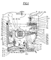
- the device for filtration illustrated in Figure 1 has an inlet port for be fixed on the end of a tap 1 capable of delivering a liquid to filter.
- the device comprises a body 2 housing a pipe comprising several parts referenced 54, 55, 56, 57, 58, 59 and likely to carry liquid from the body inlet to a cassette or filtration means 4, located on a support 38 and capable of delivering the filtered fluid at the outlet of the device.
- the filtration cassette 4 resting on the cassette holder 38, is intended to be inserted in a housing of the device susceptible to be closed by a screen 5 secured to the conical part of the chamber rack 3.
- This filtration cassette 4 comprises an outer wall 4a carrying a seal 39, a cone of reception 4b of the liquid to be filtered, a homogenization system 4c of the filtered liquid, located at the outlet of the cassette, and a membrane of filtration or microfiltration 40.
- the body of this cassette has a lateral extension 41 provided with two notches 43 forming a weakening zone for this lateral extension the thus making it easily sectionable by a sectioning member appropriate.
- sectionable part of this lateral extension has by elsewhere a predetermined profile 42, the function of which will be explained more in detail below, and is likely to be inserted, through a grid 44 whose profile is adapted to that of extension 41 in a extension, or annex part 100, of the cassette housing.
- the device also comprises a first rack 31, called “power take-off rack”, and a second rack 3 or “room rack”.
- the chamber rack 3 is guided in translation in the body 2 of the device.
- a first end of this rack chamber holder 3 is formed into a conical chamber 3a limited by a support crown 3b intended to be kept at a distance or at come into contact with the filtration means 4.
- a passage in this rack thus realizes the terminal part 58 of the pipe.
- the other end of this rack 3 is linked to the rod actuating a piston 32 capable of sliding in a vacuum chamber 33 in order to constitute an anti-drip system 34.
- This vacuum chamber 33 communicates with the hollow passage of the rack ensuring the terminal part of the pipeline, by a flexible hose 59.
- This chamber rack 3 constitutes an element of a operating assembly forming locking means / unlocking of the filtration cassette 4 on its support 38.
- These unlocking / unlocking means also include a operating handle 18 including the handle axis 19, drilled, with a channel internal 56, is integral with a toothed pinion 20 and a roller support arm 21 comprising a blind recess 22 whose opening is equipped a clip system 23.
- the free end of the arm 21 includes a roller holder 24 with spring 25, fitted with roller 26.
- This roller 26 can run on a raceway 27 formed in the body 2 of the device and comprising a first boss, or front boss, 28 and a second boss, or rear boss, 29 spaced from each other by a predetermined distance.
- the boss 29 is adjacent to a notch 30.
- the device also includes means for closing off the pipe.
- These sealing means include an element shutter, or valve, 14 slidably mounted in a housing of the body 2 and crossed by an internal passage.
- This valve 14 can thus occupy a first position in which its internal passage communicates with parts 54 and 55 of the pipeline to allow the circulation of the liquid in this pipe and through the passage internal, and a second position in which said internal passage no longer coincides with the corresponding parts of the pipeline and therefore closes these to prevent any circulation of liquid.
- the valve 14 can thus pass from its first position to its second position via a valve spring 15, the resetting is manual via a control rod manual 16 at the end of which is provided a button reset 17 capable of opening outside the body 2 of the device when the valve is in its second position.
- Triggering means are also provided, suitable for cooperate with the locking / unlocking means, to act on valve 14 and move it from its first position to its second position.
- trigger means comprise, in addition to the spring of valve 15, an element 7, acting as a lock, and susceptible to be snapped under the action of a spring 13, in a notch formed on the lateral surface of the valve 14.
- the triggering means also comprise a part 6 sliding mounted in the body of the device 2.
- This transmission part 6 has a first arm 6a intended to operate the lock and a second arm 6b, connected via a pivoting lever 8 and a relay rod 9 capable of penetrating in the blind recess 22 of the roller support arm 21, by means of locking / unlocking.
- the stroke of the lever 8 is limited by a front stop 11 and rear stop 12 formed in the body of the device, and located on either side of the axis of this lever.
- the width L3 of the opening channel 31c of the recess 31b must be, for reasons which will be explained in more detail, more important than the transverse dimension L4 of the lateral extension 41 of the cassette filtration.
- This rack 31 is guided in translation in a passage 101 of the device body 2, communicating with the annex part of the cassette compartment.
- the rack 31 comprises, in the vicinity of its free end, a sectioning member 35 consisting of one piece articulated around an axis 36 carried by the rack 31.
- This body of sectioning essentially comprises an upper part permanently pressed against the F side of the rack by a return spring 37 disposed between one end of this part upper part of the sectioning member and the rack 31.
- the part upper part of the sectioning member is extended by a part lower inclined whose underside is intended, as is will see in more detail below, coming into contact with the party sectionable cassette for sectioning. Otherwise, this inclined lower part is shaped like a foot extending substantially perpendicular to the direction of passage guide 101 of the rack 31 and substantially parallel to the sectionable part of the cassette.
- the device body 2 also includes a housing auxiliary 103 opening at one end into the annex 100 part of the cassette compartment and closed at its other end by one or several plugs 52 carried by a closure plate 53 linked to the body of the device 2.
- This auxiliary housing contains a blocking, or push-lock, 50, of rectangular section, mounted under elastic return via one or more springs 51 based on the plug (s) 52.
- this blocking member 50 is mounted movable in the auxiliary housing to enter the annex part of the cassette housing, after sectioning of the sectionable part of the latter, and take a blocking position in which it cooperates with the section 35 to prevent the latter from rising in the guide passage 101 of the power take-off rack, and therefore the return of the locking / unlocking means in their locking position, until insertion into said part appendix 100 of the cassette housing, through the grid 44, of a sectionable part of a new filtration cassette.
- the width L1 of the recess 31b is chosen greater than the width (transverse dimension) L2 of the housing auxiliary 103 and therefore of latch 50 and the width L3 of the channel opening 31c must be less than the width L2, preferably in a ratio of 30 to 70%.
- the device body has another housing 104 containing a pivoting sector 45 around an axis 47 fixed in the body of device 2.
- This pivoting sector 45 provided at one of its ends of a hook 46 is capable of pivoting around the axis 47 under elastic return by means of a spring 48, the adjustment of which the restoring force can be effected via a plug 49 secured to the closing plate 53.
- the hook 46 is naturally brought to cooperate with the corresponding hook-shaped end 105 of the extension side of the filtration cassette to ensure its blocking in said annex part 100 of the cassette housing.
- FIGS. 4 and below illustrate the operation of the device according to the invention.
- Figure 4 illustrates normal operation of the filtration.
- the opening of tap 1 allows the liquid to be filtered to circulate in the pipeline.
- the valve 14 is open and maintained in this position by latch 7.
- the lever 8 is in abutment against the front stop 11.
- the locking / unlocking means are in the position of locking, authorizing the passage of the liquid to be filtered in the channel 56.
- Chamber 3a at the end of the chamber rack 3 is applied under pressure on the seal 39 of the cassette filtration 4 by its support crown 3b.
- the clamping pressure is maintained by the force deployed by the roller spring 25 compressed by the roller 26 located on the other side of the front boss 28. In fact, one of the components of the thrust exerted on the roller 26, which rests on the boss 28 ramp, tends to maintain the means of locking / unlocking in this locking position.
- the power take-off rack 31 is in the high position and the filtration cassette 4 is locked in its housing, the extension lateral 42 being inserted in the annex 100 part of the housing to through the grid 44.
- the push-lock 50 under the effect of the spring 51, leans against the end of the lateral extension of the cassette and stays thus in the auxiliary housing 103.
- Figures 5 and 6 correspond to a pre-opening of the device to access the cassette to be replaced.
- tap 1 is closed.
- the means of locking / unlocking are operated via the handle 18 until the roller 26 reaches the second boss 29. This action causes the chamber rack 3 to rise. which allows the pre-opening of the conical chamber 3a and frees up part access to the filtration cassette 4 which however cannot be released from its housing because the screen 5 is not raised enough. Simultaneously, this movement of the locking / unlocking means causes the piston 32 to rise and the depression of the chamber 33 of the anti-drip system 34.
- the rotation of the toothed pinion 20 of the means of locking / unlocking causes the downward movement of the power take-off rack 31 in its passage 102 arranged at through the device body, which causes the organ to descend section 35, pressing against the face F of part 3 la of the rack 31, towards the sectionable part of the cassette.
- the underside of the sectioning member 35 which in fact constitutes the movable branch of a shear, and comes press the sectionable part 42 of the lateral extension of the cassette, and cuts this lateral extension to the right of the notches 43, by taking support on the fixed part of shears constituted by the support cassette holder 38.
- the sectioning member 35 repels by through its lower face, the profiled part 42 during shear, until complete separation of the lateral extension of the filtration cassette 4.
- Figures 7 and 8 correspond to the end of the movement opening the device when the locking / unlocking means reach their unlocking position. After crossing of the boss 29 by the roller 26 and housing thereof in the notch 30 of the device body 2, the means of locking / unlocking are immobilized in position unlocking.
- Figures 9 to 11 correspond to the establishment of a new filtration cassette.
- the only possible access to the push-lock 50 is through the grid 44, using a sectionable part 42 suitably profile, of a new filtration cassette by insertion of the cassette in its housing according to arrow F2.
- Profile of the sectionable lateral extension of the cassette in this case comprises an inclined ramp R which, upon its penetration in the annex housing of the cassette, is flush with the ramp R1 counterpart of the inclined lower part of the organ of sectioning 35 without striking the latter (FIG. 11); movement inserting the lateral extension 42 of the new cassette filtration, after passage through grid 44, and crossing of the sectioning member 35 continues until the meeting of the inclined slope of the hook-shaped end 46 of the sector pivoting 45. A relative movement of the end then occurs inclined hook 105 of extension 42 relative to that of hook 46, allowing the latter to be raised by pivoting under elastic return of the pivoting sector 45.
- Figures 12 to 14 correspond to the return phase of the means lock / unlock in their locked position.
- the sectioning member 35 then pivots while rising to completely free itself from lateral extension 42 and resume its initial position resting on face F of rack 31 under the action of the return spring 37.
- the piston 32 descends into its chamber and the conical chamber 3a comes into contact with the seal 39 carried by the new means filtration 4, through its support ring 3b.
- roller support arm 21 brings the clipping system back 23 in contact with the end sphere of the relay rod 9 which remains locked in stationary position because the lever 8 is itself immobilized in position by keeping the latch 7 pressed against the surface side of valve 14 via the transmission part 6.
- Channel 56 is partially aligned opposite arrival 55 and exit 57 of the corresponding parts of the pipeline, which would cause a flow of water if the valve 14 was not kept in its second position, for the case of course if tap 1 would have remained open during this whole operation.
- the end of rotation of the roller support arm 21 causes the sphere to enter end of the relay rod 19 in the blind recess 22 after crossing the clipping system 23.
- Commissioning of the filtration system with the new filtration cassette 4 can only be carried out after pressing the reset button 17, which, by means of the manual control 16, replace valve 14 in first position after compression of the valve spring 15 and latching of the latch 7 in the corresponding notch under the action of the lock spring 13. Simultaneously, the transmission part 6 is brought back to its position original.
- the lever 8 in fact constitutes additional security for the case where the lever 18 of the locking / unlocking means is accidentally operated during the period of use of the filtration device. Indeed, such a maneuver would obturation of the pipeline by means of locking / unlocking when the boss is passed 28 by the roller 26. Indeed, the rotational movement thus caused drives the end sphere of the relay rod 9 downwards by the clip assembly 23. The lever 8, not being blocked, would pivot then and, by action on the transmission part 6, would pull the lock 9 by unlocking the valve 14 and thereby cutting off the circulation of the liquid. This incident would be signaled by the reappearance of the reset 17.
- FIGS. 15 to 20 We will now describe other embodiments of a cassette for the device according to the invention illustrated in FIGS. 15 to 20, which can be inserted into a device like the one described with reference to Figures 1 to 14.
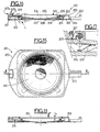
- the cassette 201 comprises a body 202 provided with a through passage 224 closed by a membrane of filtration 210 mounted substantially perpendicular to the direction general of passage 224, i.e. perpendicular to the direction of arrival of the fluid to be filtered.
- This membrane 210 is fixed on a membrane support or plate 215, mounted movable in translation relative to the body 202, under elastic return 219, in a direction substantially parallel to the general direction of the through passage 224.
- the plate 215 also includes a collection cone 205 of filtered liquids, of which the top is provided with a belt 206 constituting with a grid of foaming 207 a shower structure intended to homogenize the liquid filtered at the outlet of the cassette.
- This foaming grid 207 may have come directly from molding during the manufacture of the body 202 or reported.
- a spring washer 219 ensuring the elastic return, is kept compressed between plate 215 and a closing plate 220 of the device linked to the body 202.
- This plate 215 also has an extension 216 carrying at its end a projection 217 capable of crossing a passage corresponding 218 formed in the upper face 222 of the body 202.
- a the flared base of the collecting cone 205, the plate 215 comprises a support element 209 on which the membrane 210 is fixed.
- a bellows seal 221 ensuring a mobile tight connection between the plate 215 and the body 202, rests at one of its ends, on a joint support 203 of the body 202, supported by a rib of reinforcement 204 capable of withstanding the closing pressure necessary for obtaining watertightness when using the cassette.
- Figure 18 illustrates the configuration of the filter cassette in normal use without tearing the membrane when is subjected to the normal pressure P of the fluid to be filtered.
- the pressure force exerted by the fluid to be filtered on the membrane 210 is transmitted on plate 215 which sinks into the body 202 of a stroke h authorized by the spring 219.
- the spring 219 is calibrated so that the stroke h, in the presence of a normal pressure P of the fluid to be filtered, ie between half and 4/5 of the total admissible stroke. The rest of this race may thus be used in reserve to absorb overpressures accidental in fluid lines.
- the stroke h and the dimensions of the projection 217 are chosen so that projection 217 does not emerge of the upper face 222 of the body 202.
- any tear in the membrane restores the pressure balance on both sides of it, which causes a rise in platinum 215 in the body under the action of spring 219 by bringing out the projection 217 to signal this anomaly to the user.
- Figure 16 shows such a configuration although in this figure the membrane has been voluntarily shown not torn).
- the user will thus be able to easily detect visually by example through a window of a filter block in which would incorporated the filtration cassette, the emergence of the projection signifying a tear in the membrane.
- We could nevertheless use other signaling means for example a contact system electric, arranged on the one hand on the top 217b of the projection and on a homologous element of the filtration unit, and connected to a sight glass luminous.
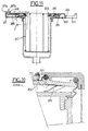
- FIGS. 15 to 18 illustrate an embodiment of a filtration cassette in which the membrane is mounted substantially parallel to the general direction of the passage crossing the body.
- the analogous elements or having functions similar to those represented in FIGS. 15 to 18 are increased by 100 compared to the ones they had on these FIGS. Only the differences between figures 19 and 20 and the figures 15 to 18 will now be described.
- the support element 309 has an upper part integral with the plate 315 and a lower part between which the filtration membrane 310, cylindrical, is arranged substantially parallel to the general direction of the crossing device.
- the displacement of the filtration membrane is caused by the longitudinal displacement of the lower part of the support 309 transmitting this displacement to the plate 315.
- Such a cassette can be inserted in a device such as that described with reference to FIGS. 1 to 14.
- the cassette body includes a sectionable lateral extension 223, 323, by the device so in particular to differentiate a new cassette from a used cassette when replacing cassettes similar to sectionable extension 42.
- the lateral extension has notches for this purpose. 224, 324 similar to the notches 43 forming a zone attenuation for sectioning.
Landscapes
- Chemical & Material Sciences (AREA)
- Chemical Kinetics & Catalysis (AREA)
- Engineering & Computer Science (AREA)
- Water Supply & Treatment (AREA)
- Environmental & Geological Engineering (AREA)
- Water Treatment By Sorption (AREA)
- Separation Using Semi-Permeable Membranes (AREA)
- Electrical Discharge Machining, Electrochemical Machining, And Combined Machining (AREA)
- Photographic Developing Apparatuses (AREA)
Description
une cassette de filtration du fluide destinée à délivrer un fluide filtré et comportant un corps de cassette équipé d'une membrane de filtration, ledit corps de cassette possédant une extension latérale comportant une partie sectionnable et complètement séparable du reste de la cassette, et
un corps de dispositif comportant une entrée de fluide, communiquant avec un logement recevant ladite cassette de filtration une sortie pour le fluide filtré, des moyens de verrouillage/déverrouillage actionnables entre une position de verrouillage de la cassette de filtration dans son logement et une position de déverrouillage de la cassette de filtration, des moyens de sectionnement actionnés par les moyens de verrouillage/déverrouillage lors du passage de leur position de verrouillage à leur position de déverrouillage pour sectionner la pertie sectionnable de la cassette de filtration, et des moyens de sécurité aptes à interdire le verrouillage dans son logement, par les moyens de verrouillage/déverrouillage, d'une cassette de filtration amputée d'une telle partie sectionnable.
- la figure 1 est une coupe schématique d'un premier mode de réalisation d'un dispositif selon l'invention,
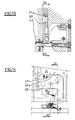
- la figure 2 illustre schématiquement plus en détail une partie du dispositif de la figure 1,
- la figure 3 est la coupe selon la ligne III-III de la figure 2, et
- les figures 4 à 14 illustrent différents cas de fonctionnement du dispositif selon l'invention,
- la figure 15 est une vue de dessus schématique d'un autre mode de réalisation d'une cassette pour le dispositif selon l'invention,
- la figure 16 est la coupe selon la ligne II-II de la figure 15,
- la figure 17 illustre plus en détail un détail L de la figure 16,
- la figure 18 est une coupe de la cassette de la figure 15 dans un cas normal de fonctionnement sans rupture de membrane, et
- la figures 19 et 20 illustrent un autre mode de réalisation d'une cassette pour le dispositif selon l'invention,
Claims (8)
- Dispositif de filtration d'un fluide, comprenant
une cassette de filtration (4) du fluide destinée à délivrer un fluide filtré et comportant un corps de cassette équipé d'une membrane de filtration, ledit corps de cassette possédant une extension latérale comportant une partie (42) sectionnable et complètement séparable du reste de la cassette, et
un corps de dispositif (2) comportant une entrée de fluide, communiquant avec un logement recevant ladite cassette de filtration (4), une sortie pour le fluide filtré, des moyens de verrouillage/déverrouillage actionnables entre une position de verrouillage de la cassette de filtration dans son logement et une position de déverrouillage de la cassette de filtration,
caractérisé par le fait que ledit corps comprend des moyens de sectionnement (31,35) actionnés par les moyens de verrouillage/déverrouillage lors du passage de leur position de verrouillage à leur position de déverrouillage pour sectionner la partie sectionnable (42) de la cassette de filtration, et des moyens de sécurité (44,35,50) aptes à interdire le verrouillage dans son logement, par les moyens de verrouillage/déverrouillage, d'une cassette de filtration amputée d'une telle partie sectionnable (42). - Dispositif selon la revendication 1, caractérisé par le fait que les moyens de verrouillage/déverrouillage comportent un pignon denté (20) susceptible d'être déplacé en rotation entre une position de verrouillage et une position de déverrouillage,
par le fait que le logement de la cassette (4) comporte une partie annexe (100) apte à loger la partie sectionnable (42) de ladite cassette,
par le fait que les moyens de sectionnement comportent une première crémaillère (31) coopérant avec le pignon denté (20), pour être guidée dans un passage (102) du corps débouchant dans le logement annexe (100) de la cassette en direction de la partie sectionnable (42) de la cassette (4), lors du passage de la position de verrouillage à la position de déverrouillage, ainsi qu'un organe de sectionnement (35) susceptible de pénétrer dans ladite partie annexe de logement de la cassette lors du déplacement de la première crémaillère (31) pour sectionner la partie sectionnable (42) de la cassette (4). - Dispositif selon la revendication 2, caractérisé par le fait que les moyens de verrouillage/déverrouillage comportent une deuxième crémaillère (3) coopérant avec ledit pignon denté (20), guidée en translation et possédant à une extrémité un moyen d'appui destiné à venir en contact de la cassette de filtration (4) dans la position de verrouillage et à être maintenu à distance de la cassette dans la position de déverrouillage,
par le fait que les moyens de sécurité comportent un organe de blocage (50) logé dans un logement auxiliaire (102) du corps, débouchant dans ladite partie annexe du logement de la cassette, monté déplaçable dans le logement auxiliaire pour pénétrer dans ladite partie annexe du logement de la cassette après sectionnement de la partie sectionnable (42) de cette dernière, et prendre une position de blocage dans laquelle il coopère avec l'organe de sectionnement (35) pour interdire sa remontée dans le passage et donc le retour des moyens de verrouillage/déverrouillage dans leur position de verrouillage jusqu'à l'insertion dans ladite partie annexe du logement de la cassette d'une partie sectionnable d'une nouvelle cassette. - Dispositif suivant la revendication 3, caractérisé par le fait que dans ladite position de blocage de l'organe de blocage (50), l'organe de sectionnement (35) obture au moins partiellement ladite partie annexe de logement,
par le fait que la partie sectionnable (42) de la cassette (4) et l'organe de sectionnement (35) comportent des profils conjugués prédéterminés (R, R1) aptes à coopérer mutuellement pour autoriser l'insertion de la partie sectionnable (42) dans ladite partie annexe de logement lors de l'insertion de la cassette dans son logement, et
par le fait que la partie sectionnable ainsi insérée dans la partie annexe de logement est apte à déplacer l'organe de blocage depuis sa position de blocage vers une position de déblocage dans laquelle il est exempt de contact avec l'organe de sectionnement pour permettre la remontée de ce dernier et le retour des moyens de verrouillage/déverrouillage dans leur position de verrouillage. - Dispositif selon la revendication 4, caractérisé par le fait que l'organe de blocage (50) est repoussé dans sa position de déblocage sous rappel élastique (51), et par le fait que le dispositif comporte un moyen de blocage auxiliaire (45, 46) de la partie sectionnable (42) de la cassette dans ladite partie annexe de logement.
- Dispositif selon l'une des revendications 1 à 5, caractérisée par le fait que l'extension latérale (41) est munie d'une zone d'affaiblissement (43).
- Dispositif selon l'une des revendications 1 à 6, caractérisé par le fait que le corps de cassette est pourvu d'un passage traversant obturé par une membrane de filtration (210, 310) fixée sur un support de membrane logé dans le corps de cassette, ce support de membrane étant monté déplaçable en translation par rapport au corps de cassette dans une direction sensiblement parallèle à la direction générale du passage traversant.
- Procédé de remplacement de la cassette de filtration verrouillée dans un logement d'un dispositif tel que défini dans l'une des revendications 1 à 7, caractérisé par le fait qu'on sectionne, lors de l'actionnement des moyens de verrouillage/déverrouillage, la partie sectionnable de la cassette, et on ampute complètement la cassette de la partie sectionnée pour permettre l'extraction de la cassette hors du logement, et par le fait qu'on interdit le verrouillage de toute cassette de remplacement amputée d'une telle partie sectionnable, en empêchant l'actionnement des moyens de verrouillage/déverrouillage.
Applications Claiming Priority (6)
| Application Number | Priority Date | Filing Date | Title |
|---|---|---|---|
| FR9306991A FR2709255B1 (fr) | 1993-06-10 | 1993-06-10 | Dispositif et cassette sécurisés de filtration d'un fluide et procédé de remplacement d'une cassette de filtration sécurisée dans un dispositif correspondant. |
| FR9306989 | 1993-06-10 | ||
| FR9306991 | 1993-06-10 | ||
| FR9306989A FR2706324B1 (fr) | 1993-06-10 | 1993-06-10 | Dispositif sécurité de filtration d'un fluide, notamment de l'eau utilisée en milieu hospitalier. |
| FR9306990A FR2709254B1 (fr) | 1993-06-10 | 1993-06-10 | Cassette sécurisée de filtration d'un fluide, notamment de l'eau utilisée en milieu médical. |
| FR9306990 | 1993-06-10 |
Publications (2)
| Publication Number | Publication Date |
|---|---|
| EP0628334A1 EP0628334A1 (fr) | 1994-12-14 |
| EP0628334B1 true EP0628334B1 (fr) | 2003-03-26 |
Family
ID=27252758
Family Applications (1)
| Application Number | Title | Priority Date | Filing Date |
|---|---|---|---|
| EP94401302A Expired - Lifetime EP0628334B1 (fr) | 1993-06-10 | 1994-06-10 | Dispositif et cassette sécurisés de filtration d'un fluide et procédé de remplacement d'une cassette de filtration sécurisée dans un dispositif correspondant |
Country Status (3)
| Country | Link |
|---|---|
| EP (1) | EP0628334B1 (fr) |
| AT (1) | ATE235294T1 (fr) |
| DE (1) | DE69432329D1 (fr) |
Families Citing this family (1)
| Publication number | Priority date | Publication date | Assignee | Title |
|---|---|---|---|---|
| CN111484127A (zh) * | 2020-04-30 | 2020-08-04 | 海南甘泉实业有限公司 | 一种水污染治理装置 |
Family Cites Families (2)
| Publication number | Priority date | Publication date | Assignee | Title |
|---|---|---|---|---|
| US3542202A (en) * | 1969-04-11 | 1970-11-24 | Technical Fabricators | Filter unit |
| US4689147A (en) * | 1985-09-27 | 1987-08-25 | Nalge Company | Plastic filter assembly |
-
1994
- 1994-06-10 EP EP94401302A patent/EP0628334B1/fr not_active Expired - Lifetime
- 1994-06-10 DE DE69432329T patent/DE69432329D1/de not_active Expired - Lifetime
- 1994-06-10 AT AT94401302T patent/ATE235294T1/de not_active IP Right Cessation
Also Published As
| Publication number | Publication date |
|---|---|
| ATE235294T1 (de) | 2003-04-15 |
| DE69432329D1 (de) | 2003-04-30 |
| EP0628334A1 (fr) | 1994-12-14 |
Similar Documents
| Publication | Publication Date | Title |
|---|---|---|
| EP0156669B1 (fr) | Dispositif de sécurité à la fermeture et à l'ouverture d'un appareil de cuisson sous pression | |
| EP3692285B1 (fr) | Robinet et réservoir(s) de fluide sous pression | |
| FR2738030A1 (fr) | Loquet a claquement | |
| CH652309A5 (fr) | Dispositif de succion et d'irrigation, notamment pour un usage medical. | |
| EP2088358A1 (fr) | Elément femelle de raccord et raccord rapide incorporant un tel élément | |
| CA1273288A (fr) | Vanne de securite pour puits petrolier et outils en vue de la mise en oeuvre de ladite vanne | |
| CA2603032A1 (fr) | Dispositif antivol et anti-deversement pour reservoir de liquide, notamment reservoir de carburant | |
| EP0737782B1 (fr) | Dispositif de verrouillage libérable des deux cÔtés d'un regard | |
| FR2962658A1 (fr) | Systeme de ligne de vie pour protection antichute, coulisseau, support de cable et manchon | |
| EP2297504A2 (fr) | Ensemble raccorde de maniere securisee d'un tube a une piece rigide alesee | |
| EP0628334A1 (fr) | Dispositif et cassette sécurisés de filtration d'un fluide et procédé de remplacement d'une cassette de filtration sécurisée dans un dispositif correspondant | |
| FR2709255A1 (fr) | Dispositif et cassette sécurisés de filtration d'un fluide et procédé de remplacement d'une cassette de filtration sécurisée dans un dispositif correspondant. | |
| WO1995002876A1 (fr) | Dispositif declencheur d'alarme, notamment pour installation de detection d'incendie | |
| EP0466564B1 (fr) | Récipient démontable, pouvant supporter une pression interne | |
| EP0728098A1 (fr) | Largueur hydrostatique d'equipements de securite | |
| EP3685712B1 (fr) | Appareil de cuisson sous pression à sécurité ultime | |
| WO2010146283A1 (fr) | Borne d'incendie et procédé de sécurisation d'une borne d'incendie | |
| EP1959089B1 (fr) | Dispositif de protection d'une ouverture contre les inondations et les effractions | |
| FR2706324A1 (fr) | Dispositif sécurité de filtration d'un fluide, notamment de l'eau utilisée en milieu hospitalier. | |
| FR2883808A1 (fr) | Dispositif antivol et anti-deversement pour reservoir de liquide, notamment reservoir de carburant | |
| EP0738523A1 (fr) | Tête d'extincteur à sécurité antiréarmement | |
| FR2907874A1 (fr) | Economiseur d'eau a commande a impulsion manuelle adaptable sur le bec d'un robinet | |
| EP1215342B1 (fr) | Ensemble de verrouillage d'une plaque d'obturation d'un accès à une chambre souterraine | |
| FR2842239A1 (fr) | Dispositif d'arret pour volets, portes, ou autres ouvrants | |
| EP1059405A1 (fr) | Serrure et enveloppe de protection équipée d'une telle serrure |
Legal Events
| Date | Code | Title | Description |
|---|---|---|---|
| PUAI | Public reference made under article 153(3) epc to a published international application that has entered the european phase |
Free format text: ORIGINAL CODE: 0009012 |
|
| AK | Designated contracting states |
Kind code of ref document: A1 Designated state(s): AT CH DE ES FR GB IT LI NL PT SE |
|
| 17P | Request for examination filed |
Effective date: 19950612 |
|
| RIN1 | Information on inventor provided before grant (corrected) |
Inventor name: GODET, CHRISTIAN Inventor name: PICCARDI, MICHEL Inventor name: BUISSON, PHILIPPE |
|
| 17Q | First examination report despatched |
Effective date: 19951229 |
|
| GRAG | Despatch of communication of intention to grant |
Free format text: ORIGINAL CODE: EPIDOS AGRA |
|
| GRAG | Despatch of communication of intention to grant |
Free format text: ORIGINAL CODE: EPIDOS AGRA |
|
| GRAG | Despatch of communication of intention to grant |
Free format text: ORIGINAL CODE: EPIDOS AGRA |
|
| GRAH | Despatch of communication of intention to grant a patent |
Free format text: ORIGINAL CODE: EPIDOS IGRA |
|
| GRAH | Despatch of communication of intention to grant a patent |
Free format text: ORIGINAL CODE: EPIDOS IGRA |
|
| GRAA | (expected) grant |
Free format text: ORIGINAL CODE: 0009210 |
|
| AK | Designated contracting states |
Designated state(s): AT CH DE ES FR GB IT LI NL PT SE |
|
| PG25 | Lapsed in a contracting state [announced via postgrant information from national office to epo] |
Ref country code: NL Free format text: LAPSE BECAUSE OF FAILURE TO SUBMIT A TRANSLATION OF THE DESCRIPTION OR TO PAY THE FEE WITHIN THE PRESCRIBED TIME-LIMIT Effective date: 20030326 Ref country code: IT Free format text: LAPSE BECAUSE OF FAILURE TO SUBMIT A TRANSLATION OF THE DESCRIPTION OR TO PAY THE FEE WITHIN THE PRE;WARNING: LAPSES OF ITALIAN PATENTS WITH EFFECTIVE DATE BEFORE 2007 MAY HAVE OCCURRED AT ANY TIME BEFORE 2007. THE CORRECT EFFECTIVE DATE MAY BE DIFFERENT FROM THE ONE RECORDED.SCRIBED TIME-LIMIT Effective date: 20030326 Ref country code: GB Free format text: LAPSE BECAUSE OF FAILURE TO SUBMIT A TRANSLATION OF THE DESCRIPTION OR TO PAY THE FEE WITHIN THE PRESCRIBED TIME-LIMIT Effective date: 20030326 Ref country code: AT Free format text: LAPSE BECAUSE OF FAILURE TO SUBMIT A TRANSLATION OF THE DESCRIPTION OR TO PAY THE FEE WITHIN THE PRESCRIBED TIME-LIMIT Effective date: 20030326 |
|
| REG | Reference to a national code |
Ref country code: GB Ref legal event code: FG4D Free format text: NOT ENGLISH |
|
| REG | Reference to a national code |
Ref country code: CH Ref legal event code: EP |
|
| REF | Corresponds to: |
Ref document number: 69432329 Country of ref document: DE Date of ref document: 20030430 Kind code of ref document: P |
|
| PG25 | Lapsed in a contracting state [announced via postgrant information from national office to epo] |
Ref country code: SE Free format text: LAPSE BECAUSE OF FAILURE TO SUBMIT A TRANSLATION OF THE DESCRIPTION OR TO PAY THE FEE WITHIN THE PRESCRIBED TIME-LIMIT Effective date: 20030626 Ref country code: PT Free format text: LAPSE BECAUSE OF FAILURE TO SUBMIT A TRANSLATION OF THE DESCRIPTION OR TO PAY THE FEE WITHIN THE PRESCRIBED TIME-LIMIT Effective date: 20030626 |
|
| PG25 | Lapsed in a contracting state [announced via postgrant information from national office to epo] |
Ref country code: DE Free format text: LAPSE BECAUSE OF FAILURE TO SUBMIT A TRANSLATION OF THE DESCRIPTION OR TO PAY THE FEE WITHIN THE PRESCRIBED TIME-LIMIT Effective date: 20030627 |
|
| PG25 | Lapsed in a contracting state [announced via postgrant information from national office to epo] |
Ref country code: LI Free format text: LAPSE BECAUSE OF NON-PAYMENT OF DUE FEES Effective date: 20030630 Ref country code: CH Free format text: LAPSE BECAUSE OF NON-PAYMENT OF DUE FEES Effective date: 20030630 |
|
| NLV1 | Nl: lapsed or annulled due to failure to fulfill the requirements of art. 29p and 29m of the patents act | ||
| GBV | Gb: ep patent (uk) treated as always having been void in accordance with gb section 77(7)/1977 [no translation filed] |
Effective date: 20030326 |
|
| PG25 | Lapsed in a contracting state [announced via postgrant information from national office to epo] |
Ref country code: ES Free format text: LAPSE BECAUSE OF FAILURE TO SUBMIT A TRANSLATION OF THE DESCRIPTION OR TO PAY THE FEE WITHIN THE PRESCRIBED TIME-LIMIT Effective date: 20030930 |
|
| PLBE | No opposition filed within time limit |
Free format text: ORIGINAL CODE: 0009261 |
|
| STAA | Information on the status of an ep patent application or granted ep patent |
Free format text: STATUS: NO OPPOSITION FILED WITHIN TIME LIMIT |
|
| REG | Reference to a national code |
Ref country code: CH Ref legal event code: PL |
|
| PG25 | Lapsed in a contracting state [announced via postgrant information from national office to epo] |
Ref country code: FR Free format text: LAPSE BECAUSE OF NON-PAYMENT OF DUE FEES Effective date: 20040227 |
|
| 26N | No opposition filed |
Effective date: 20031230 |
|
| REG | Reference to a national code |
Ref country code: FR Ref legal event code: ST |