EP0628007B1 - Tamper indicating packages - Google Patents
Tamper indicating packages Download PDFInfo
- Publication number
- EP0628007B1 EP0628007B1 EP93905474A EP93905474A EP0628007B1 EP 0628007 B1 EP0628007 B1 EP 0628007B1 EP 93905474 A EP93905474 A EP 93905474A EP 93905474 A EP93905474 A EP 93905474A EP 0628007 B1 EP0628007 B1 EP 0628007B1
- Authority
- EP
- European Patent Office
- Prior art keywords
- ink
- pattern
- adhesive
- seal
- bag
- Prior art date
- Legal status (The legal status is an assumption and is not a legal conclusion. Google has not performed a legal analysis and makes no representation as to the accuracy of the status listed.)
- Expired - Lifetime
Links
Images


Classifications
-
- G—PHYSICS
- G09—EDUCATION; CRYPTOGRAPHY; DISPLAY; ADVERTISING; SEALS
- G09F—DISPLAYING; ADVERTISING; SIGNS; LABELS OR NAME-PLATES; SEALS
- G09F3/00—Labels, tag tickets, or similar identification or indication means; Seals; Postage or like stamps
- G09F3/02—Forms or constructions
- G09F3/0291—Labels or tickets undergoing a change under particular conditions, e.g. heat, radiation, passage of time
- G09F3/0292—Labels or tickets undergoing a change under particular conditions, e.g. heat, radiation, passage of time tamper indicating labels
-
- B—PERFORMING OPERATIONS; TRANSPORTING
- B65—CONVEYING; PACKING; STORING; HANDLING THIN OR FILAMENTARY MATERIAL
- B65D—CONTAINERS FOR STORAGE OR TRANSPORT OF ARTICLES OR MATERIALS, e.g. BAGS, BARRELS, BOTTLES, BOXES, CANS, CARTONS, CRATES, DRUMS, JARS, TANKS, HOPPERS, FORWARDING CONTAINERS; ACCESSORIES, CLOSURES, OR FITTINGS THEREFOR; PACKAGING ELEMENTS; PACKAGES
- B65D33/00—Details of, or accessories for, sacks or bags
- B65D33/16—End- or aperture-closing arrangements or devices
- B65D33/34—End- or aperture-closing arrangements or devices with special means for indicating unauthorised opening
-
- B—PERFORMING OPERATIONS; TRANSPORTING
- B65—CONVEYING; PACKING; STORING; HANDLING THIN OR FILAMENTARY MATERIAL
- B65D—CONTAINERS FOR STORAGE OR TRANSPORT OF ARTICLES OR MATERIALS, e.g. BAGS, BARRELS, BOTTLES, BOXES, CANS, CARTONS, CRATES, DRUMS, JARS, TANKS, HOPPERS, FORWARDING CONTAINERS; ACCESSORIES, CLOSURES, OR FITTINGS THEREFOR; PACKAGING ELEMENTS; PACKAGES
- B65D35/00—Pliable tubular containers adapted to be permanently or temporarily deformed to expel contents, e.g. collapsible tubes for toothpaste or other plastic or semi-liquid material; Holders therefor
- B65D35/24—Pliable tubular containers adapted to be permanently or temporarily deformed to expel contents, e.g. collapsible tubes for toothpaste or other plastic or semi-liquid material; Holders therefor with auxiliary devices
- B65D35/32—Winding keys
- B65D35/34—Winding keys connected to, or associated with, tube holders
Definitions
- This invention relates to tamper indicating packages and labels, and in particular, to packages made of plastics materials, of a type which are commonly used for transporting cash or other valuables, and which are arranged so as to ensure that no tampering with the contents is possible, without such tampering being made immediately obvious on inspection.
- a tamper indicating sealing tape, label or package including a transparent or translucent flexible plastics base material, a pattern printed on the base material in a silicone acrylate which forms a discontinuous release layer, a layer of opaque ink applied over the release pattern, and a layer of adhesive applied over the opaque ink.
- the pattern of the release layer preferably spells out some wording such as "void", and thus, if the ink layer is opaque, and the base film is transparent or translucent, these words will be revealed, as soon as the seal is pulled apart, and it will then be very difficult for the interrupted areas of ink to be reconstituted in such a way that the wording is no longer visible.
- systems of this kind depend on the fact that the ink has low cohesive strength, and will adhere to whichever surface has the greatest surface energy.
- seals of this kind are useful to prevent opening of the bag by freezing it, which reduces the adhesivity of the adhesive.
- the adhesive layer, and the ink layer are made continuous, and the discontinuities are provided by the silicone release layer.
- such an arrangement does have the disadvantage that it is necessary to apply three successive coatings to the material, i.e. the release layer, the ink, and the adhesive.
- the present invention therefore seeks to provide a tamper evident sealing system which has improved performance and at the same time is simpler to manufacture.
- the present invention provides a closure for a security bag or a security label, comprising a seal for two surfaces which can be contacted together to close the seal, and including an ink pattern and an adhesive pattern, characterised in that both patterns are comprised of sets of strips or lines which are so arranged that they overlap, but do not match, at least after the seal has been closed.
- the ink pattern is applied first to one of the surfaces to be sealed, and overlaid by the adhesive pattern.
- the ink pattern is applied to one surface and the adhesive is applied to the opposing surface. Because the ink receiving surface must be of low surface energy great care must be used to ensure that the pattern is not damaged by normal handling before the seal is achieved. These embodiments ensure tamper evidence both at normal operating temperatures and when the adhesive strength of the adhesive has been diminished by low temperatures.
- the supporting surface is first treated by corona discharge so as to increase surface energy and the surface is subsequently treated with a coating which reduces the surface energy to a predetermined degree for example, a coating of silicone acrylate or a blend of a silicone copolymer with other polymers or copolymers.
- a similar effect may be achieved more simply by leaving the surface untreated and instead, using an ink which has adequate bonding to the surface.
- These inks include those which are based on nitro-cellulose and polyamides, possibly modified by the addition of wax to obtain the right balance of adhesive and cohesive strengths.
- titanium esters may be added to increase the temperature resistance
- nitro-cellulose urethane inks with titanates may also be utilised.
- ink vehicles may be used including inks which are cured by UV light and use water rather than solvents as their diluent.
- the adhesive strips or lines may be applied in straight lines or in undulating lines produced by moving the extruder head across the substrate or conversely moving the substrate across the glue head.
- the adhesive pattern is applied first to one of the surfaces and the ink pattern is superimposed on it.
- tamper evidence can be achieved even when the cohesive strength of the adhesive has been diminished e.g. by high temperatures, in addition to the situation at normal and low temperatures. This is because the failure of the seal by cohesive failure still results in ink being transferred from one surface to the other and matching of the pattern becomes extremely difficult.
- the application of the ink over the adhesive surface is best carried out by a non-contacting process such as an ink jet printer.
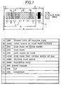
- a small section of a sealing flap for a security bag comprising a region 2 extending along one edge of the flap, which is adapted to be heat sealed onto a corresponding edge of the bag to be sealed, for example along the top edge of the bag as illustrated in Figure 3.
- the main body of the flap 4 carries a series of transversely extending glue lines, and preferably, as shown, these comprise a number of narrow lines 6, 8, 10 etc, and a broader line 12 which is positioned so that in use, it overlies a slit 14 in the face of the bag, which forms the normal opening.
- the flap Before the lines of glue are applied to the flap, as illustrated, it is printed with a distinctive non matching opaque ink pattern comprised of sets of strips or lines. After application of the glue, the exposed glued surface is covered with a silicone release tape to protect it, before the bag is closed. As can be seen from Figure 3, when the release tape is removed and the flap is pressed down over the mouth of the bag to close it, the lines of glue will adhere to the face of the bag, and in particular, the glued area 12 will effectively seal the slit opening 14.
- the ink pattern will become detached from the flap, in those areas that coincide with adhesive lines, whereas the ink will remain on the flap, in the intervening areas, and thus, the printed ink pattern will be clearly disrupted.
- the ink must have a relatively low cohesive strength, so that the pattern will be clearly broken at the interface between the glued and non glued regions.
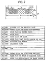
- the flap illustrated in Figure 2 carries a further area of adhesive on its edge 2a, and otherwise functions in the same way as the flap of Figure 1.
- Figures 4, 5 and 6 illustrate various different ways of arranging the adhesive stripes on the flap, such as lengthwise of the flap as illustrated in Figures 4 and 5, and of arranging the flap itself Figure 6.
- the arrangement may be of the "double seal" type as exemplified by our British Patent No. 2,145,997.
- the flap is first printed with a distinctive ink pattern, and the glue lines are subsequently laid down on top of the ink.
- the arrangement may be "inverted" with lines of adhesive 20 applied first to a corona treated plastics (e.g. polythene) flap surface, and very narrow lines 22 of ink, subsequently laid down on top of the adhesive.
- a corona treated plastics e.g. polythene
- very narrow lines 22 of ink subsequently laid down on top of the adhesive.
- This also has the advantage that a complex and "programmable" pattern can then be laid down under automatic control (for example by computer) and in this way the seal can embody a code which can be automatically read at the receiving end of the package, and which will be unreadable if the seal has been tampered with.
- the pattern could be made to form a "bar code”.
- the surface that the flap is brought into contact with, to form the seal is preferably treated, for example by the known process of corona discharge, so that the adhesive lines will adhere strongly to it, and thus, if a subsequent attempt is made to peel the seal apart, the considerably greater cohesive strength of the lines of adhesive will cause the narrow "bridging" regions of ink to break, thus ensuring, as before, that the overall pattern is visibly disrupted.
- any of the arrangements discussed above could be modified by incorporating parallel sets of glue lines, comprising adhesive with different operating temperature ranges.
- glue lines comprising adhesive with different operating temperature ranges.
- the glue lines having the "colder" operating range must be confined between other sets, since, at normal ambient temperatures, they will be liquid and likely to "run out”. Such an arrangement will, therefore, protect the bag against tampering, even if it is frozen to a very low temperature or heated to a very high temperature, because there will always be one or other set of patterns which is disrupted by the subsequent tampering.
- While the invention is particularly suitable for sealing devices it may also be used for labels where it is desirable that the removal of a label should be evident both on the label itself and the surface from which it has been removed. This is particulary valuable if the bar code design is incorporated thereby preventing the switching of bar coded labels which may give incorrect specification or price.
Abstract
Description
- This invention relates to tamper indicating packages and labels, and in particular, to packages made of plastics materials, of a type which are commonly used for transporting cash or other valuables, and which are arranged so as to ensure that no tampering with the contents is possible, without such tampering being made immediately obvious on inspection.
- One known system of this kind is shown in our WO91/04199 entitled "Tamper Indicating Package", which discloses, inter-alia, a tamper indicating sealing tape, label or package including a transparent or translucent flexible plastics base material, a pattern printed on the base material in a silicone acrylate which forms a discontinuous release layer, a layer of opaque ink applied over the release pattern, and a layer of adhesive applied over the opaque ink.
- The effect of this arrangement is that if the seal is peeled apart, the ink will be left on the base material, in the intervening spaces formed by the silicone acrylate release pattern, whereas they will come away from the base film, in the filled areas of the silicone acrylate pattern, because the adhesive will cause them to adhere more strongly to the overlying material in those areas.
- The pattern of the release layer preferably spells out some wording such as "void", and thus, if the ink layer is opaque, and the base film is transparent or translucent, these words will be revealed, as soon as the seal is pulled apart, and it will then be very difficult for the interrupted areas of ink to be reconstituted in such a way that the wording is no longer visible.
- Basically, systems of this kind depend on the fact that the ink has low cohesive strength, and will adhere to whichever surface has the greatest surface energy. In particular, seals of this kind are useful to prevent opening of the bag by freezing it, which reduces the adhesivity of the adhesive. In most such existing systems, the adhesive layer, and the ink layer are made continuous, and the discontinuities are provided by the silicone release layer. However, such an arrangement does have the disadvantage that it is necessary to apply three successive coatings to the material, i.e. the release layer, the ink, and the adhesive.
- The present invention therefore seeks to provide a tamper evident sealing system which has improved performance and at the same time is simpler to manufacture.
- Accordingly, the present invention provides a closure for a security bag or a security label, comprising a seal for two surfaces which can be contacted together to close the seal, and including an ink pattern and an adhesive pattern, characterised in that both patterns are comprised of sets of strips or lines which are so arranged that they overlap, but do not match, at least after the seal has been closed.
- In one embodiment of the invention the ink pattern is applied first to one of the surfaces to be sealed, and overlaid by the adhesive pattern.
- When this surface is brought into contact with an opposing surface, so as to form a seal, because the ink adheres more strongly to the adhesive on one side, than to the surface on the other, any attempt to open the seal results in the ink pattern being "broken up", because those areas which coincide with the adhesive will become transferred with the adhesive to the opposing surface, whilst those areas which do not coincide with the adhesive will, of course, remain on the original surface on which they were printed. In this way, a very distinct disruption of the seal area is produced, making it extremely difficult or impossible to reseal the bag without this being apparent.
- In another embodiment of the invention the ink pattern is applied to one surface and the adhesive is applied to the opposing surface. Because the ink receiving surface must be of low surface energy great care must be used to ensure that the pattern is not damaged by normal handling before the seal is achieved. These embodiments ensure tamper evidence both at normal operating temperatures and when the adhesive strength of the adhesive has been diminished by low temperatures.
- Normally, in order to achieve a required level of adhesivity, on a polythene surface, for example, the supporting surface is first treated by corona discharge so as to increase surface energy and the surface is subsequently treated with a coating which reduces the surface energy to a predetermined degree for example, a coating of silicone acrylate or a blend of a silicone copolymer with other polymers or copolymers. However, a similar effect may be achieved more simply by leaving the surface untreated and instead, using an ink which has adequate bonding to the surface. These inks include those which are based on nitro-cellulose and polyamides, possibly modified by the addition of wax to obtain the right balance of adhesive and cohesive strengths. Additionally or alternatively, titanium esters may be added to increase the temperature resistance, and nitro-cellulose urethane inks with titanates may also be utilised. On other surfaces more appropriate ink vehicles may be used including inks which are cured by UV light and use water rather than solvents as their diluent.
- The adhesive strips or lines may be applied in straight lines or in undulating lines produced by moving the extruder head across the substrate or conversely moving the substrate across the glue head.
- In a further alternative embodiment of the invention the adhesive pattern is applied first to one of the surfaces and the ink pattern is superimposed on it.
- In this embodiment tamper evidence can be achieved even when the cohesive strength of the adhesive has been diminished e.g. by high temperatures, in addition to the situation at normal and low temperatures. This is because the failure of the seal by cohesive failure still results in ink being transferred from one surface to the other and matching of the pattern becomes extremely difficult.
- The application of the ink over the adhesive surface is best carried out by a non-contacting process such as an ink jet printer.
- Some embodiments of the invention will now be described by way of example, with reference to the accompanying drawings in which:
- Figure 1 is a plan view of part of a bag closure flap of a first type in accordance with the invention;
- Figure 2 is a plan view of a closure of a second type;
- Figure 3 is a schematic view of a security bag incorporating a closure of the type shown in Figure 1;
- Figure 4 illustrates a second type of bag incorporating a seal according to the invention;
- Figure 5 illustrates a third example of a security bag;
- Figure 6 illustrates a fourth example of a security bag; and
- Figure 7 is a partial view of an alternative form of seal in accordance with the invention.
-
- Referring first to Figure 1, a small section of a sealing flap for a security bag is illustrated, comprising a
region 2 extending along one edge of the flap, which is adapted to be heat sealed onto a corresponding edge of the bag to be sealed, for example along the top edge of the bag as illustrated in Figure 3. The main body of theflap 4 carries a series of transversely extending glue lines, and preferably, as shown, these comprise a number ofnarrow lines broader line 12 which is positioned so that in use, it overlies aslit 14 in the face of the bag, which forms the normal opening. - Before the lines of glue are applied to the flap, as illustrated, it is printed with a distinctive non matching opaque ink pattern comprised of sets of strips or lines. After application of the glue, the exposed glued surface is covered with a silicone release tape to protect it, before the bag is closed. As can be seen from Figure 3, when the release tape is removed and the flap is pressed down over the mouth of the bag to close it, the lines of glue will adhere to the face of the bag, and in particular, the glued
area 12 will effectively seal the slit opening 14. - If an attempt is then made to peel away the flap from the face of the bag, the ink pattern will become detached from the flap, in those areas that coincide with adhesive lines, whereas the ink will remain on the flap, in the intervening areas, and thus, the printed ink pattern will be clearly disrupted. For this purpose, the ink must have a relatively low cohesive strength, so that the pattern will be clearly broken at the interface between the glued and non glued regions.
- Alternatively, instead of being attached with a heat seal, as suggested in Figure 1, the flap illustrated in Figure 2 carries a further area of adhesive on its edge 2a, and otherwise functions in the same way as the flap of Figure 1.
- Figures 4, 5 and 6 illustrate various different ways of arranging the adhesive stripes on the flap, such as lengthwise of the flap as illustrated in Figures 4 and 5, and of arranging the flap itself Figure 6. In the latter case, where it will be seen that the flap is connected to the bag below the mouth, the arrangement may be of the "double seal" type as exemplified by our British Patent No. 2,145,997.
- The above examples are of the general type in which the flap is first printed with a distinctive ink pattern, and the glue lines are subsequently laid down on top of the ink. However, in an alternative arrangement illustrated diagrammatically in Figure 7, the arrangement may be "inverted" with lines of adhesive 20 applied first to a corona treated plastics (e.g. polythene) flap surface, and very
narrow lines 22 of ink, subsequently laid down on top of the adhesive. Obviously, it is undesirable to use a "contact method" of applying the ink onto a surface already carrying adhesive, and it has been found that a good non contact method of applying the ink, is to use an "ink jet" printer. This also has the advantage that a complex and "programmable" pattern can then be laid down under automatic control (for example by computer) and in this way the seal can embody a code which can be automatically read at the receiving end of the package, and which will be unreadable if the seal has been tampered with. For example, the pattern could be made to form a "bar code". - In use, the surface that the flap is brought into contact with, to form the seal, is preferably treated, for example by the known process of corona discharge, so that the adhesive lines will adhere strongly to it, and thus, if a subsequent attempt is made to peel the seal apart, the considerably greater cohesive strength of the lines of adhesive will cause the narrow "bridging" regions of ink to break, thus ensuring, as before, that the overall pattern is visibly disrupted.
- As a further precaution against unauthorised opening of the seals by freezing or heating, it is also envisaged that any of the arrangements discussed above could be modified by incorporating parallel sets of glue lines, comprising adhesive with different operating temperature ranges. For example, there could be three sets of glue lines, a first one of which has a normal operating temperature range such as -5°C to +30°C, whilst the next adjacent one has a very low operating range as much as -30°C to +10°C, and the final set has a high operating range such as 25°C to 60°C. It will be appreciated that the glue lines having the "colder" operating range must be confined between other sets, since, at normal ambient temperatures, they will be liquid and likely to "run out". Such an arrangement will, therefore, protect the bag against tampering, even if it is frozen to a very low temperature or heated to a very high temperature, because there will always be one or other set of patterns which is disrupted by the subsequent tampering.
- Although the examples have been described specifically as having both the ink and adhesive pre-coated onto the same surface, it will also be appreciated that, particularly in the case of a bag closure, it would be possible to apply the pattern of adhesive to one surface and the pattern of ink to the other surface, since the effect of the finished closure will still be the same.
- While the invention is particularly suitable for sealing devices it may also be used for labels where it is desirable that the removal of a label should be evident both on the label itself and the surface from which it has been removed. This is particulary valuable if the bar code design is incorporated thereby preventing the switching of bar coded labels which may give incorrect specification or price.
Claims (9)
- A closure for a security bag or a security label, comprising a seal for two surfaces which can be contacted together to close the seal, and including an ink pattern and an adhesive pattern, characterised in that both patterns are comprised of sets of strips or lines which are so arranged that they overlap, but do not match, at least after the seal has been closed.
- A closure according to claim 1, in which the ink pattern is applied to one of the surfaces, and the adhesive pattern is then applied over the ink pattern.
- A closure according to claim 1 in which the adhesive pattern is applied to one of the surfaces, and the ink pattern is then applied over the adhesive pattern.
- A closure according to any preceding claim in which the ink is applied by means of an ink jet printer.
- A closure according to claim 1 in which the ink pattern is applied to one of the surfaces, and the adhesive pattern is applied to the other surface.
- A closure according to any preceding claim in which the adhesive strips are laid down in an undulating pattern by moving the extruder head and the receiving substrate relatively to one another.
- A closure according to any of claims 1 to 6 for a bag made from polythene, in which the ink is based on nitro-cellulose and polyamides.
- A security bag having a closure according to claim 7, the bag being made from polythene, in which the ink also includes wax and/or titanium esters.
- A closure according to any of claims 1 to 6 in which the ink is based on nitro-cellulose urethanes and includes titanates.
Applications Claiming Priority (3)
| Application Number | Priority Date | Filing Date | Title |
|---|---|---|---|
| GB929203931A GB9203931D0 (en) | 1992-02-25 | 1992-02-25 | Tamper indicating packages |
| GB9203931 | 1992-02-25 | ||
| PCT/GB1993/000385 WO1993016933A1 (en) | 1992-02-25 | 1993-02-25 | Tamper indicating packages |
Publications (2)
| Publication Number | Publication Date |
|---|---|
| EP0628007A1 EP0628007A1 (en) | 1994-12-14 |
| EP0628007B1 true EP0628007B1 (en) | 2000-06-28 |
Family
ID=10710953
Family Applications (1)
| Application Number | Title | Priority Date | Filing Date |
|---|---|---|---|
| EP93905474A Expired - Lifetime EP0628007B1 (en) | 1992-02-25 | 1993-02-25 | Tamper indicating packages |
Country Status (7)
| Country | Link |
|---|---|
| EP (1) | EP0628007B1 (en) |
| AT (1) | ATE194120T1 (en) |
| AU (1) | AU3638793A (en) |
| DE (1) | DE69328925T2 (en) |
| ES (1) | ES2149808T3 (en) |
| GB (2) | GB9203931D0 (en) |
| WO (1) | WO1993016933A1 (en) |
Families Citing this family (6)
| Publication number | Priority date | Publication date | Assignee | Title |
|---|---|---|---|---|
| US6270256B1 (en) | 1997-04-07 | 2001-08-07 | Sealed Air Corporation | Tamper evident bag |
| GB9810359D0 (en) | 1998-05-14 | 1998-07-15 | Britton Security Products | Coin & document bag |
| GB9811190D0 (en) | 1998-05-22 | 1998-07-22 | Britton Security Products | Multiple use security bag |
| DE19963711A1 (en) * | 1999-12-29 | 2001-07-05 | Beiersdorf Ag | Adhesive tape for proving the unauthorized opening of a packaging |
| US20140270584A1 (en) * | 2013-03-14 | 2014-09-18 | Ronald H. Exner | Reclosable packages and methods of manufacturing |
| US10725077B2 (en) | 2016-12-01 | 2020-07-28 | Nxp B.V. | Tamper detector |
Family Cites Families (8)
| Publication number | Priority date | Publication date | Assignee | Title |
|---|---|---|---|---|
| DE2803434A1 (en) * | 1978-01-26 | 1979-08-02 | Koenig Kg Claus | SELF-ADHESIVE CLEAR FILM |
| GB2138396B (en) * | 1983-04-21 | 1987-12-31 | Decoflex Ltd | Bags with tamper indicators |
| US4711368A (en) * | 1986-04-11 | 1987-12-08 | Leon Simons | Tamper proof package with electrical circuit |
| GB2200337A (en) * | 1987-01-28 | 1988-08-03 | Metal Box Plc | Plastic bags |
| US4972953A (en) * | 1989-06-14 | 1990-11-27 | Ivy Hill Corporation | Tamper-evident packaging, method of making same and intermediate therein |
| FR2649078B1 (en) * | 1989-06-28 | 1991-09-20 | Brossier Michel | METHOD, DEVICE AND MEANS FOR IMPLEMENTING A PACKAGING OPENING INDICATOR |
| GB8921108D0 (en) * | 1989-09-18 | 1989-11-01 | Interpoly Ltd | Tamper indicating package |
| US5042842A (en) * | 1990-06-26 | 1991-08-27 | Avery International Corporation | High security label |
-
1992
- 1992-02-25 GB GB929203931A patent/GB9203931D0/en active Pending
-
1993
- 1993-02-25 AT AT93905474T patent/ATE194120T1/en not_active IP Right Cessation
- 1993-02-25 EP EP93905474A patent/EP0628007B1/en not_active Expired - Lifetime
- 1993-02-25 AU AU36387/93A patent/AU3638793A/en not_active Abandoned
- 1993-02-25 ES ES93905474T patent/ES2149808T3/en not_active Expired - Lifetime
- 1993-02-25 DE DE69328925T patent/DE69328925T2/en not_active Expired - Lifetime
- 1993-02-25 GB GB9416770A patent/GB2279936B/en not_active Expired - Lifetime
- 1993-02-25 WO PCT/GB1993/000385 patent/WO1993016933A1/en active IP Right Grant
Also Published As
| Publication number | Publication date |
|---|---|
| ATE194120T1 (en) | 2000-07-15 |
| GB2279936B (en) | 1996-06-05 |
| GB9203931D0 (en) | 1992-04-08 |
| EP0628007A1 (en) | 1994-12-14 |
| GB9416770D0 (en) | 1994-11-09 |
| AU3638793A (en) | 1993-09-13 |
| ES2149808T3 (en) | 2000-11-16 |
| GB2279936A (en) | 1995-01-18 |
| DE69328925T2 (en) | 2001-03-01 |
| DE69328925D1 (en) | 2000-08-03 |
| WO1993016933A1 (en) | 1993-09-02 |
Similar Documents
| Publication | Publication Date | Title |
|---|---|---|
| AU768465B2 (en) | Tamper evident tapes and labels | |
| US5588679A (en) | Tamper resistant labeling | |
| EP0403532B1 (en) | Security deposit bag | |
| EP0491099B1 (en) | Tamper evident closure and tamper evident method | |
| AU646815B2 (en) | Tamper indicating package | |
| US6455119B2 (en) | Label structure | |
| US5584580A (en) | Tamper-resistant envelope closure | |
| US6048098A (en) | Tamper-resistant envelope | |
| JPH01226533A (en) | Imprinting method of over-wrapping packaging | |
| EP0183489B1 (en) | A security bag | |
| EP0628007B1 (en) | Tamper indicating packages | |
| US5788377A (en) | Tamper-resistant envelope | |
| CN104812862B (en) | Transparent safety diaphragm | |
| CA2196606A1 (en) | Tamper evident seal and tape | |
| JPH04373Y2 (en) | ||
| US6234536B1 (en) | Label structure | |
| RU2343560C1 (en) | Protective label | |
| JP4550992B2 (en) | Package | |
| AU687373B2 (en) | Improved novel tamper evident closure | |
| CA2461583A1 (en) | Tamper evident tape and label | |
| JP4157171B2 (en) | Sealed paper | |
| CA2029810A1 (en) | Tamper evident closure | |
| JPH06286768A (en) | Tamper-evident seal | |
| JPS61134783A (en) | Sealing tape | |
| JPH04201865A (en) | New closure of opening and revelation |
Legal Events
| Date | Code | Title | Description |
|---|---|---|---|
| PUAI | Public reference made under article 153(3) epc to a published international application that has entered the european phase |
Free format text: ORIGINAL CODE: 0009012 |
|
| 17P | Request for examination filed |
Effective date: 19940822 |
|
| AK | Designated contracting states |
Kind code of ref document: A1 Designated state(s): AT BE CH DE DK ES FR GB GR IE IT LI LU MC NL PT SE |
|
| 17Q | First examination report despatched |
Effective date: 19960613 |
|
| GRAG | Despatch of communication of intention to grant |
Free format text: ORIGINAL CODE: EPIDOS AGRA |
|
| GRAG | Despatch of communication of intention to grant |
Free format text: ORIGINAL CODE: EPIDOS AGRA |
|
| GRAH | Despatch of communication of intention to grant a patent |
Free format text: ORIGINAL CODE: EPIDOS IGRA |
|
| RAP1 | Party data changed (applicant data changed or rights of an application transferred) |
Owner name: BRITTON SECURITY PACKAGING LIMITED |
|
| GRAH | Despatch of communication of intention to grant a patent |
Free format text: ORIGINAL CODE: EPIDOS IGRA |
|
| GRAA | (expected) grant |
Free format text: ORIGINAL CODE: 0009210 |
|
| AK | Designated contracting states |
Kind code of ref document: B1 Designated state(s): AT BE CH DE DK ES FR GB GR IE IT LI LU MC NL PT SE |
|
| PG25 | Lapsed in a contracting state [announced via postgrant information from national office to epo] |
Ref country code: LI Free format text: LAPSE BECAUSE OF FAILURE TO SUBMIT A TRANSLATION OF THE DESCRIPTION OR TO PAY THE FEE WITHIN THE PRESCRIBED TIME-LIMIT Effective date: 20000628 Ref country code: GR Free format text: LAPSE BECAUSE OF NON-PAYMENT OF DUE FEES Effective date: 20000628 Ref country code: CH Free format text: LAPSE BECAUSE OF FAILURE TO SUBMIT A TRANSLATION OF THE DESCRIPTION OR TO PAY THE FEE WITHIN THE PRESCRIBED TIME-LIMIT Effective date: 20000628 Ref country code: AT Free format text: LAPSE BECAUSE OF FAILURE TO SUBMIT A TRANSLATION OF THE DESCRIPTION OR TO PAY THE FEE WITHIN THE PRESCRIBED TIME-LIMIT Effective date: 20000628 |
|
| REF | Corresponds to: |
Ref document number: 194120 Country of ref document: AT Date of ref document: 20000715 Kind code of ref document: T |
|
| REG | Reference to a national code |
Ref country code: CH Ref legal event code: EP |
|
| REG | Reference to a national code |
Ref country code: IE Ref legal event code: FG4D |
|
| REF | Corresponds to: |
Ref document number: 69328925 Country of ref document: DE Date of ref document: 20000803 |
|
| ITF | It: translation for a ep patent filed |
Owner name: BIANCHETTI - BRACCO - MINOJA S.R.L. |
|
| PG25 | Lapsed in a contracting state [announced via postgrant information from national office to epo] |
Ref country code: PT Free format text: LAPSE BECAUSE OF FAILURE TO SUBMIT A TRANSLATION OF THE DESCRIPTION OR TO PAY THE FEE WITHIN THE PRESCRIBED TIME-LIMIT Effective date: 20000928 Ref country code: DK Free format text: LAPSE BECAUSE OF FAILURE TO SUBMIT A TRANSLATION OF THE DESCRIPTION OR TO PAY THE FEE WITHIN THE PRESCRIBED TIME-LIMIT Effective date: 20000928 |
|
| ET | Fr: translation filed | ||
| REG | Reference to a national code |
Ref country code: ES Ref legal event code: FG2A Ref document number: 2149808 Country of ref document: ES Kind code of ref document: T3 |
|
| REG | Reference to a national code |
Ref country code: CH Ref legal event code: PL |
|
| PG25 | Lapsed in a contracting state [announced via postgrant information from national office to epo] |
Ref country code: LU Free format text: LAPSE BECAUSE OF NON-PAYMENT OF DUE FEES Effective date: 20010225 Ref country code: GB Free format text: LAPSE BECAUSE OF NON-PAYMENT OF DUE FEES Effective date: 20010225 |
|
| PG25 | Lapsed in a contracting state [announced via postgrant information from national office to epo] |
Ref country code: IE Free format text: LAPSE BECAUSE OF NON-PAYMENT OF DUE FEES Effective date: 20010226 |
|
| PG25 | Lapsed in a contracting state [announced via postgrant information from national office to epo] |
Ref country code: MC Free format text: LAPSE BECAUSE OF NON-PAYMENT OF DUE FEES Effective date: 20010228 |
|
| PLBE | No opposition filed within time limit |
Free format text: ORIGINAL CODE: 0009261 |
|
| STAA | Information on the status of an ep patent application or granted ep patent |
Free format text: STATUS: NO OPPOSITION FILED WITHIN TIME LIMIT |
|
| 26N | No opposition filed | ||
| GBPC | Gb: european patent ceased through non-payment of renewal fee |
Effective date: 20010225 |
|
| REG | Reference to a national code |
Ref country code: IE Ref legal event code: MM4A |
|
| PGFP | Annual fee paid to national office [announced via postgrant information from national office to epo] |
Ref country code: SE Payment date: 20080227 Year of fee payment: 16 |
|
| PGFP | Annual fee paid to national office [announced via postgrant information from national office to epo] |
Ref country code: BE Payment date: 20080306 Year of fee payment: 16 |
|
| NLS | Nl: assignments of ep-patents |
Owner name: BRITTON DECOFLEX LIMITED Effective date: 20080820 |
|
| REG | Reference to a national code |
Ref country code: FR Ref legal event code: CD Ref country code: FR Ref legal event code: CA |
|
| REG | Reference to a national code |
Ref country code: FR Ref legal event code: TP |
|
| BERE | Be: lapsed |
Owner name: *BRITTON SECURITY PACKAGING LTD Effective date: 20090228 |
|
| EUG | Se: european patent has lapsed | ||
| PG25 | Lapsed in a contracting state [announced via postgrant information from national office to epo] |
Ref country code: BE Free format text: LAPSE BECAUSE OF NON-PAYMENT OF DUE FEES Effective date: 20090228 |
|
| PG25 | Lapsed in a contracting state [announced via postgrant information from national office to epo] |
Ref country code: SE Free format text: LAPSE BECAUSE OF NON-PAYMENT OF DUE FEES Effective date: 20090226 |
|
| PGFP | Annual fee paid to national office [announced via postgrant information from national office to epo] |
Ref country code: FR Payment date: 20120306 Year of fee payment: 20 |
|
| PGFP | Annual fee paid to national office [announced via postgrant information from national office to epo] |
Ref country code: DE Payment date: 20120228 Year of fee payment: 20 |
|
| PGFP | Annual fee paid to national office [announced via postgrant information from national office to epo] |
Ref country code: IT Payment date: 20120224 Year of fee payment: 20 |
|
| PGFP | Annual fee paid to national office [announced via postgrant information from national office to epo] |
Ref country code: NL Payment date: 20120228 Year of fee payment: 20 |
|
| REG | Reference to a national code |
Ref country code: DE Ref legal event code: R071 Ref document number: 69328925 Country of ref document: DE |
|
| REG | Reference to a national code |
Ref country code: NL Ref legal event code: V4 Effective date: 20130225 |
|
| PG25 | Lapsed in a contracting state [announced via postgrant information from national office to epo] |
Ref country code: DE Free format text: LAPSE BECAUSE OF EXPIRATION OF PROTECTION Effective date: 20130226 |
|
| PGFP | Annual fee paid to national office [announced via postgrant information from national office to epo] |
Ref country code: ES Payment date: 20120227 Year of fee payment: 20 |
|
| REG | Reference to a national code |
Ref country code: ES Ref legal event code: FD2A Effective date: 20130716 |
|
| PG25 | Lapsed in a contracting state [announced via postgrant information from national office to epo] |
Ref country code: ES Free format text: LAPSE BECAUSE OF EXPIRATION OF PROTECTION Effective date: 20130226 |