EP0627252B1 - Rotary adsorption/desorption gas treating apparatus - Google Patents
Rotary adsorption/desorption gas treating apparatus Download PDFInfo
- Publication number
- EP0627252B1 EP0627252B1 EP93119962A EP93119962A EP0627252B1 EP 0627252 B1 EP0627252 B1 EP 0627252B1 EP 93119962 A EP93119962 A EP 93119962A EP 93119962 A EP93119962 A EP 93119962A EP 0627252 B1 EP0627252 B1 EP 0627252B1
- Authority
- EP
- European Patent Office
- Prior art keywords
- adsorbing
- gas
- cassette
- treating apparatus
- rotary drum
- Prior art date
- Legal status (The legal status is an assumption and is not a legal conclusion. Google has not performed a legal analysis and makes no representation as to the accuracy of the status listed.)
- Expired - Lifetime
Links
- 238000002336 sorption--desorption measurement Methods 0.000 title claims description 10
- 238000003795 desorption Methods 0.000 claims description 29
- 238000001179 sorption measurement Methods 0.000 claims description 29
- 230000002093 peripheral effect Effects 0.000 claims description 12
- 238000007789 sealing Methods 0.000 claims description 9
- 239000013076 target substance Substances 0.000 claims description 8
- 238000010276 construction Methods 0.000 description 19
- 238000005192 partition Methods 0.000 description 6
- 239000000126 substance Substances 0.000 description 4
- 238000012986 modification Methods 0.000 description 3
- 230000004048 modification Effects 0.000 description 3
- 239000002904 solvent Substances 0.000 description 3
- 230000000694 effects Effects 0.000 description 2
- 238000010422 painting Methods 0.000 description 2
- 230000015572 biosynthetic process Effects 0.000 description 1
- 230000000903 blocking effect Effects 0.000 description 1
- 238000012423 maintenance Methods 0.000 description 1
- 238000004519 manufacturing process Methods 0.000 description 1
- 239000003973 paint Substances 0.000 description 1
- 239000007787 solid Substances 0.000 description 1
- 238000000638 solvent extraction Methods 0.000 description 1
Images





Classifications
-
- B—PERFORMING OPERATIONS; TRANSPORTING
- B01—PHYSICAL OR CHEMICAL PROCESSES OR APPARATUS IN GENERAL
- B01D—SEPARATION
- B01D53/00—Separation of gases or vapours; Recovering vapours of volatile solvents from gases; Chemical or biological purification of waste gases, e.g. engine exhaust gases, smoke, fumes, flue gases, aerosols
- B01D53/02—Separation of gases or vapours; Recovering vapours of volatile solvents from gases; Chemical or biological purification of waste gases, e.g. engine exhaust gases, smoke, fumes, flue gases, aerosols by adsorption, e.g. preparative gas chromatography
- B01D53/06—Separation of gases or vapours; Recovering vapours of volatile solvents from gases; Chemical or biological purification of waste gases, e.g. engine exhaust gases, smoke, fumes, flue gases, aerosols by adsorption, e.g. preparative gas chromatography with moving adsorbents, e.g. rotating beds
-
- B—PERFORMING OPERATIONS; TRANSPORTING
- B01—PHYSICAL OR CHEMICAL PROCESSES OR APPARATUS IN GENERAL
- B01D—SEPARATION
- B01D2258/00—Sources of waste gases
- B01D2258/02—Other waste gases
- B01D2258/0258—Other waste gases from painting equipments or paint drying installations
-
- B—PERFORMING OPERATIONS; TRANSPORTING
- B01—PHYSICAL OR CHEMICAL PROCESSES OR APPARATUS IN GENERAL
- B01D—SEPARATION
- B01D2259/00—Type of treatment
- B01D2259/40—Further details for adsorption processes and devices
- B01D2259/40011—Methods relating to the process cycle in pressure or temperature swing adsorption
- B01D2259/40077—Direction of flow
- B01D2259/40081—Counter-current
-
- B—PERFORMING OPERATIONS; TRANSPORTING
- B01—PHYSICAL OR CHEMICAL PROCESSES OR APPARATUS IN GENERAL
- B01D—SEPARATION
- B01D2259/00—Type of treatment
- B01D2259/40—Further details for adsorption processes and devices
- B01D2259/40083—Regeneration of adsorbents in processes other than pressure or temperature swing adsorption
- B01D2259/40088—Regeneration of adsorbents in processes other than pressure or temperature swing adsorption by heating
- B01D2259/4009—Regeneration of adsorbents in processes other than pressure or temperature swing adsorption by heating using hot gas
Definitions
- the present invention relates to a rotary adsorption/desorption type gas treating apparatus for eliminating a target substance from treatmemt subject gas containing the substance by adsorbing the substance and then desorbing the same.
- the apparatus is used, for instance, for separating and eliminating a paint solvent from atmosphere containing the solvent exhausted from a painting factory.
- Figs. 8 and 9 show a known apparatus of the above-described type.
- this apparatus includes a rotary drum 1' having a plurality of gas-passage compartments 4' arranged side by side along the peripheral direction of the drum and defines, in the peripheral direction, an adsorption zone X' for allowing passage of treatment subject gas G through the compartment(s) 4' in the radial direction of the drum and a desorption zone Y' for allowing passage of refreshing gas H through the compartment(s) 4' in the generally opposite radial direction.
- a gas-permeable adsorbing element 7' in the form of a flat plate element, with an inclination relative to the radial direction of the drum.
- the respective compartments 4' are alternately brought into registered relationship with the adsorption zone X' and the desorption zone Y'.
- the adsorption zone X' as the subject gas is passed through the adsorbing element 7', the target substance contained in the gas is adsorbed on the adsorbing element 7'.
- the substance on the element 7' is desorbed to the refreshing gas H, such that the element 7' becomes refreshed to be ready for a next adsorption/desorption cycle.
- the apparatus can treat the subject gas G continuously.
- each gas-passage compartment 4' includes a partition wall 3' which serves to separate this compartment 4' from another compartment adjacent thereto.
- the partition wall 3' serves as an inter-compartment partition for partitioning between the adsorption zone X' and the desorption zone Y' in order to prevent gas leakage therebetween.
- the adsorbing element 7' in the form of a flat plate is disposed with an inclination relative to the radius of the rotary drum 1', thereby to reduce the diameter of the drum 1' while maximizing the gas passage area of the adsorbing element 7'.
- FR-A-2 079 007 discloses a rotary adsorption/desorption gas treating apparatus having a rotary element with a plurality of adsorbing means in form of solid acceptor rods and with the rotational range of the rotary element being divided between an adsorption zone and a desorption zone.
- DE-U-92 04 169 discloses a filter-cartridge for dust-arresters being removably mounted by a screw means and thereby allowing a simplified assembling and disassembling of the filter.
- a primary object of the present invention is to provide an improved gas treating apparatus which enables further reduction of the diameter of the rotary drum while retaining a large gas treatment capacity and which also allows to easily attach and detatch the adsorbing means even when a plurality of adsorbing means is disposed in the rotary drum.
- a rotary adsorption/desorption gas treating apparatus for fulfilling the above-noted object, comprises the features of claim 1.
- the respective gas passage compartments are alternately brought into registered relationship with the adsorption zone and the desorption zone.
- the subject gas or the refreshing gas is respectively introduced through the gas-permeable adsorbing mat mounted within the compartment, in the direction along the rotation axis of the drum.
- the apparatus is capable of continuously treating the treatment-subject gas.
- the adsorbing mat when assembled with the cassette and mounted therewith within the compartment, includes a portion oriented normal or inclined relative to a side end face of the rotary drum.
- the arrangement of the invention can allow the mat to obtain a larger gas passage area within the limit of the area of the side end face of the drum.
- the passage of subject gas or refreshing gas through the adsorbing mat in the adsorption or desorption zone takes place in the direction along the rotation axis of the rotary drum. That is, unlike the conventional construction shown in Figs. 8 and 9, the construction of the invention eliminates the necessity of reserving the subject gas and refreshing gas passages at the inner central portion of the rotary drum. In this way, the construction has eliminated the limit in the reduction of the drum diameter due to the formation of the gas passages at the inner center of this drum.
- the adsorbing mat can maintain a large gas passage area thanks to the arrangement in which the adsorbing mat is so disposed as to have a portion thereof oriented normal or inclined relative to the side end face of the drum.
- the invention has fully achieved its intended object of providing an improved gas treating apparatus which enables further reduction of the diameter of the rotary drum while retaining a large gas treatment capacity. Consequently, the entire apparatus too may be formed compact while achieving higher treatment capacity.
- the adsorbing-element cassette is formed like a container with the adsorbing mat being tensely attached on a periphery of the container.
- the container-like cassette includes an opened face which is to be oriented normal to the direction of the gas passage to and from the gas passage compartment when the cassette is mounted in position within the compartment.
- the subject gas in the adsorption zone or the refreshing gas in the desorption zone is caused to pass the adsorbing mat attached around the adsorbing-element cassette in the form of a container. More particularly, the subject gas or refreshing gas is introduced through the opened face of the container-like cassette into the inside of the cassette and then the gas exits the cassette through the adsorbing mat attached around the periphery of the cassette to the outside. In this case, the opened face functions as a gas inlet opening. Alternately, the gas is introduced into the cassette through the mat attached around the periphery and then the gas exits the cassette from the opened face. In this case, the opened face functions as a gas outlet opening.
- the adsorbing-element cassette is constructed in the form of a container and the adsorbing mat is tensely attached to the periphery of the container. Therefore, in comparison with the planar arrangement of the adsorbing mat having the same area, the adsorbing-element cassette can be formed more compact and also mounting and dismounting operations of the cassette are rendered easier.
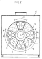
- a numeral 1 denotes a rotary drum driven to rotate by a drive unit 2.
- This rotary drum 1 includes a drum body having an outer peripheral wall 1a, an inner peripheral wall 1b, one side wall 1c and the other side wall 1d and also includes, inside the drum body, a plurality of gas-passage compartments 4 arranged side by side in the peripheral direction of the drum and separated from one another by inner partition walls 3.
- the side wall 1c defines a plurality of circular openings 5, with three of them being disposed in a zigzag format at each gas-passage compartment 4.
- the other side wall 1d defines a plurality of sector-shaped recesses 6 corresponding in number and position to the circular openings 5. Then, by using these circular openings 5 and the sector recesses 6 as gas inlet or outlet openings, treatment-subject gas is caused to pass through the respective gas-passage compartments 4 in a direction along a rotation axis P of the rotary drum.
- each gas-passage compartment 4 there is detachably mounted an adsorbing-element cassette 8 having a gas-permeable adsorbing mat 7.
- the above-described rotary drum 1 is housed in a drum chamber 9, inside of which is partitioned between an inlet section 9a and an outlet section 9b by means of an inner partition wall 10.
- the inlet section 9a is communicated with a feed passage 11 for introducing the treatment-subject gas G, while the outlet section 9b is communicated with an exhaust passage 12 for exhausting the subject gas G after adsorption treatment.
- the outlet section 9b includes a feed passage 13 for hot refreshing (desorbing) gas H, the passage being partitioned from the rest of the section 9b.
- the inlet section 9a includes an exhaust passage 14 for the refreshing gas H' after desorption operation, with the exhaust passage 14 being partitioned from the rest of the section 9a.
- an opened terminal end face of the refreshing-gas feed passage 13 is placed in close opposition to the side end face 1c of the drum, and an opened terminal face of the refreshing-gas exhaust passage 14 is placed in close opposition to the other side end face 1d of the drum.
- a portion extending through the inlet section 9a and the outlet section 9b provides an adsorption zone X.
- a desorption zone Y is provided by a further portion in the rotational range located at the above-described predetermined phase where the opened terminal end face of the refreshing-gas feed passage 13 is opposed, across the rotary drum, to that of the refreshing-gas exhaust passage 14.
- the respective gas-passage compartments 4 are alternately brought into registered relationship with the adsorption zone X and the desorption zone Y.
- the treatment-subject gas G and in the desorption zone Y, the refreshing gas H, is caused to pass the compartments 4 in the direction along the rotational axis P of the rotary drum, in which compartments 4 each gas passes through the adsorbing mats 7 of the adsorbing-element cassettes 8 mounted within the compartments 4.
- the apparatus can treat the subject gas G in a continuous manner.
- a numeral 15 denotes a gas shield plate for blocking gas passage into those gas-passage compartments 4 which are located at borders between the adsorption zone X and the desorption zone Y. More particularly, this gas shield plate 15, in cooperation with the inner partition walls 3, serves to prevent gas leakage which would otherwise occur when one compartment 4 is located across the adsorption zone X and the desorption zone Y.
- Fig. 3 shows the construction of the adsorbing-element cassette 8.
- the cassette 8 includes a cassette body 8a in the form of a bottom-equipped cylinder (an example of a container-like device) having a peripheral wall defining a plurality of through holes, and the adsorbing mat 7 is tensely wrapped around the peripheral wall and fastened by fasteners 8b to the cassette body 8a at opposed ends of this cylindrical body 8a.
- this arrangement utilizes a cassette guide 16 extending from one circular opening 5 of the side end drum face 1c into the interior of the compartment 4.
- this cassette guide 16 comprises a frame-like structure formed by a plurality of rod members 16a fixedly provided on the side end face 1c of the rotary drum.
- the adsorbing-element cassette 8 is fitted outwardly onto each cassette guide 16 in such a manner that the opened end face of the adsorbing-element cassette 8 having the form of a bottom-equipped container is brought into registered opposition to the circular opening 5, namely, the opened end face of the cassette is placed in normal to the direction of gas passage through the compartment 4.
- the cassette 8 is fixed in place by means of a screw construction 17 provided at the bottom of the cassette body 8a and a projecting end of the cassette guide 16.
- the opened end face of the adsorbing-element cassette 8 in the form of the bottom-equipped container functions as a gas inlet opening for allowing passage of the treatment-subject gas G from the outside of the periphery of the cassette through the adsorbing mat 7 attached on the periphery to the inside of the cassette.
- the opened end face of the adsorbing-element cassette 8 functions as a gas inlet opening for allowing passage of the refreshing gas H from the inside of the cassette 8 through the adsorbing mat 7 on the periphery to the outside of the cassette.
- the direction of the passage of the subject or refreshing gas through the gas-passage compartment 4 in the adsorption and desorption zone X and Y is aligned with the rotational axis of the rotary drum; and the adsorbing mat 7 is set normal to the side end face of the drum when the adsorbing-element cassette 8 is mounted within the drum.
- this adsorbing-element cassette 8 can be formed compact and can be easily mounted and dismounted to and from the drum.
- a reference numeral 18 denotes a sealing element attached to a brim portion of the opened end of the adsorbing-element cassette 8. With fixing of the cassette 8 by the screw construction 17, the sealing element 18 is pressed between the brim portion of the cassette 8 and the side end wall 1c of the drum, thereby to provide a sealing effect therebetween.
- the rotary drum 1 may be formed with a smaller diameter such that the circular openings 5 of the side end wall 1c may correspond in one-to-one relationship to each of the gas-passage compartments 4. Conversely, in case the construction is to treat a larger amount of the subject gas, the rotary drum 1 will be formed with a larger diameter such that four or more of the adsorbing-element cassettes 8 will be provided to each of the compartment 4.
- the constructions may commonly use the same cassettes 8. This will be advantageous for minimizing the manufacturing and maintenance costs of the cassettes 8.
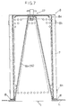
- the cassette guide 16 comprises a frame-like structure consisting essentially of a plurality of rod members 16a. While, various modifications of this cassette guide 16 are conceivable. For instance, as shown in Fig. 6, the cassette guide 16 may comprise a ring-shaped band member 16b provided at the peripheral edge of the circular opening 5 of the side end wall 1c of the drum. Further alternatively, as shown in Fig. 7, the cassette guide 16 may comprise a porous conical member 16c which functions also as a gas flow rectifier means inside the cassette 8.
- the sealing element 18 is interposed between the brim portion of the opened end of the adsorbing-element cassette 8 and the side end wall 1c of the rotary drum.
- the sealing element 18 may be interposed between the ring-shaped band member 16b acting as the cassette guide 16 and the opened inner peripheral portion of the adsorbing-element cassette 8. Further modifications in the sealing arrangement in the attachment of the cassette 8 will be readily conceivable for those skilled in the art.
- the treatment-subject gas is introduced from the outside of the periphery of the adsorbing-element cassette 8 in the form of a bottom-equipped container to the inside of this cassette 8.
- the refreshing gas is introduced from the inside of the cassette 8 and exhausted through the periphery of the same to the outside.
- the subject gas it is also conceivable for the subject gas to travel from the inside of the cassette 8 to the outside of the periphery of the same in the adsorption zone X and for the refreshing gas to travel from the outside of the periphery of the cassette 8 to the inside of the same in the desorption zone Y.
- the subject or refreshing gas may travel from the inside of the cassette 8 to the outside of the periphery of the same, or in the opposite direction, i.e. from the outside of the periphery of the cassette to the inside of the same.
- the specific construction of the adsorbing-element cassette 8 for allowing the adsorbing mat 7 thereof to have a portion oriented normal or inclined relative to the side end face of the drum when the cassette 8 is mounted to the drum or in the specific construction of attaching the adsorbing mat 7 to the cassette 8.
- the specific shape of this container-like cassette 8 is not limited to the bottom-equipped cylindrical configuration, but may be a bottom-equipped angular cylindrical configuration, a conical configuration, a bowl-like configuration and so on.
- the specific configuration of the adsorbing-element cassette 8 is not particularly limited in the present invention.
- the treatment-subject gas G is not limited to the solvent-containing exhaust gas from the painting factory.
- the rotary adsorption/desorption gas treating apparatus of the present invention may be used for treating various types of gas in a variety of fields of application.
- the rotary drum 1 is disposed with the rotational axis P thereof oriented horizontal. Instead, the drum 1 may be disposed with the axis P oriented vertical. Further, the specific gas flow passage construction provided around the rotary drum 1 is not limited to that disclosed in the foregoing embodiment.
Landscapes
- Chemical & Material Sciences (AREA)
- Engineering & Computer Science (AREA)
- Analytical Chemistry (AREA)
- General Chemical & Material Sciences (AREA)
- Oil, Petroleum & Natural Gas (AREA)
- Chemical Kinetics & Catalysis (AREA)
- Separation Of Gases By Adsorption (AREA)
- Treating Waste Gases (AREA)
Description
Claims (13)
- A rotary adsorption/desorption gas treating apparatus having:a rotary drum (1) rotatable along a rotation axis (P) including a plurality of gas passage compartments (4) arranged in a peripheral direction of the drum (1); andadsorbing means (8) provided inside each of said gas passage compartments (4) for adsorbing an elimination-target substance contained in a treatment subject gas (G);a rotational range of said rotary drum (1) being divided between an adsorption zone (X) and a desorption zone (Y), in said adsorption zone (X), the treatment subject gas (G) being allowed to pass said gas passage compartments (4) in a direction along said rotation axis (P) of the rotary drum (1), in said desorption zone (Y), a refreshing gas (H) being allowed to pass said gas passage compartments (4) in the direction along said rotation axis (P) of the rotary drum (1);
characterized in thatsaid adsorbing means (8) is an adsorbing-element cassette including a gas-permeable adsorbing mat (7) for adsorbing the elimination-target substance contained in the treatment subject gas (G);said adsorbing-element cassette (8) is fitted outwardly on a cassette guide (16) secured to a side end wall (1c) of said rotary drum (1);said adsorbing-element cassette (8) has one end thereof opposing a circular opening (5) defined in the side end wall (1c) of the rotary drum (1), said adsorbing-element cassette (8) being attached in place by screw means (17) extending between the other end of said adsorbing-element cassette (8) and said circular opening (5). - A gas treating apparatus as defined in claim 1,
characterized in that
said adsorbing-element cassette (8) includes a plurality of rod members (16a) secured to said side end wall (1c). - A gas treating apparatus as defined in claim 1,
characterized in that
said adsorbing-element cassette (8) has said one end thereof contacting with a ring-shaped band member (16b) provided at a peripheral edge of said circular opening (5), said adsorbing-element cassette (8) being attached to said ring-shaped band member (16b) by said screw means (17). - A gas treating apparatus as defined in claim 1,
characterized in that
said adsorbing-element cassette (8) includes a porous conical member (16c) functioning as a gas flow rectifier means, said porous conical member (16c) being secured to said side end wall (1c). - A rotary adsorption/desorption gas treating apparatus as defined in claim 1,
characterized in that
said adsorbing mat (7), when mounted in said compartment (4), includes a portion oriented normal or inclined relative to a side end face of said rotary drum (1). - A gas treating apparatus as defined in claim 1,
characterized in that
a gas shield plate (15) is provided at a border between said adsorption zone (X) and said desorption zone (Y) to prevent gas leakage therebetween. - A gas treating apparatus as defined in claim 1,
characterized in that
said adsorbing-element cassette (8) is formed like a container with an adsorbing mat (7) being tensely attachted on a periphery of said adsorbing-element cassette (8). - A gas treating apparatus as defined in claim 7,
characterized in that
said adsorbing mat (7) is attached within said gas passage compartment (4) in such a manner that said adsorbing mat (7) has a portion thereof oriented normal or inclined relative to an end face of said rotary drum (1). - A gas treating apparatus as defined in claim 1,
characterized in that
said adsorbing-element cassette (8) is formed like a container with said adsorbing mat (7) being tensely attached on a periphery of the container, said container-like cassette (8) including an opened face which is to be oriented normal to the direction of the gas passage to and from said gas passage compartment (4) when said cassette (8) is mounted in position within said compartment (4). - A gas treating apparatus as defined in claim 1,
characterized in that
a plurality of said adsorbing-element cassettes (8) are detachably mounted within each said gas passage compartment (4). - A gas treating apparatus as defined in claim 1 or in claim 9,
characterized in that
said adsorbing-element cassette (8) includes a cassette body (8a) in the form of a bottom-equipped container having a peripheral wall defining a plurality of through holes. - A gas treating apparatus as defined in claim 1,
characterized in that
a sealing element (18) is pressed between said adsorbing-element cassette (8) and said side end wall (1c) of the rotary drum (1) thereby to provide sealing therebetween. - A gas treating apparatus as defined in claim 3,
characterized in that
a sealing element (18) is pressed between said adsorbing-element cassette (8) and said ring-shaped band member (16b) for preventing gas leakage therebetween.
Applications Claiming Priority (2)
| Application Number | Priority Date | Filing Date | Title |
|---|---|---|---|
| JP133603/93 | 1993-06-03 | ||
| JP13360393A JP3312055B2 (en) | 1993-06-03 | 1993-06-03 | Rotary adsorption / desorption type gas processing equipment |
Publications (2)
| Publication Number | Publication Date |
|---|---|
| EP0627252A1 EP0627252A1 (en) | 1994-12-07 |
| EP0627252B1 true EP0627252B1 (en) | 1998-01-14 |
Family
ID=15108666
Family Applications (1)
| Application Number | Title | Priority Date | Filing Date |
|---|---|---|---|
| EP93119962A Expired - Lifetime EP0627252B1 (en) | 1993-06-03 | 1993-12-10 | Rotary adsorption/desorption gas treating apparatus |
Country Status (7)
| Country | Link |
|---|---|
| US (1) | US5464468A (en) |
| EP (1) | EP0627252B1 (en) |
| JP (1) | JP3312055B2 (en) |
| BR (1) | BR9401769A (en) |
| CZ (1) | CZ286241B6 (en) |
| DE (1) | DE69316340T2 (en) |
| ES (1) | ES2112378T3 (en) |
Families Citing this family (29)
| Publication number | Priority date | Publication date | Assignee | Title |
|---|---|---|---|---|
| DE4427793C2 (en) * | 1994-08-08 | 1997-01-30 | Behr Gmbh & Co | Device for removing the harmful and aromatic substances from an air flow supplied to the vehicle interior |
| US5628819A (en) * | 1995-09-28 | 1997-05-13 | Calgon Carbon Corporation | Method and apparatus for continuous adsorption of adsorbable contaminates and adsorber regeneration |
| US5788744A (en) * | 1996-11-21 | 1998-08-04 | Durr Industries, Inc. | Recirculation of desorption outlet for rotary concentrator |
| US5891219A (en) * | 1998-01-13 | 1999-04-06 | Durr Environmental, Inc. | Two stage rotary concentrator |
| US5980615A (en) * | 1998-01-22 | 1999-11-09 | Roe; Robert J. | Compact air dryer |
| JP2000117039A (en) * | 1998-10-15 | 2000-04-25 | Toshiba Corp | Gas separation device |
| JP3963608B2 (en) | 1999-03-25 | 2007-08-22 | 株式会社大気社 | Air component concentrator |
| AU5466400A (en) | 1999-06-04 | 2000-12-28 | Flair Corporation | Rotating drum adsorber process and system |
| DE19929556A1 (en) * | 1999-06-18 | 2000-12-21 | Mannesmann Ag | Device for transferring moisture from flow of gas and/or onto flow of gas for use in fuel cell system, has rotor with multiple cells coated with an absorption substance |
| JP2001038144A (en) * | 1999-08-04 | 2001-02-13 | Taikisha Ltd | Gas treating device |
| JP4004195B2 (en) * | 1999-10-29 | 2007-11-07 | 株式会社大気社 | Rotating type adsorption / desorption type gas treatment equipment |
| DE10016079A1 (en) | 2000-03-31 | 2001-10-04 | Alstom Power Nv | Method for removing carbon dioxide from the exhaust gas of a gas turbine system and device for carrying out the method |
| DE10134904A1 (en) * | 2001-07-18 | 2003-02-06 | Tsu Tech Dienste Sicherheit Un | Plant combining batch processes for quasi-continuous operation in e.g. recovery of oxygen from air, comprises rotary process chambers around cylindrical valve system |
| JP4159451B2 (en) * | 2003-11-06 | 2008-10-01 | 株式会社大気社 | Heat-resistant hermetic wall structure, regenerative gas treatment device, and adsorption / desorption gas treatment device |
| US7018447B2 (en) * | 2004-04-05 | 2006-03-28 | Dürr Systems, Inc. | Method of cleaning a rotary concentrator |
| KR100874855B1 (en) | 2004-04-23 | 2008-12-18 | 두르 시스템즈 인코포레이티드 | Cleaning method of rotary adsorber |
| CN101603603B (en) | 2004-06-28 | 2011-06-15 | 株式会社大气社 | Rotary directional control valve and heat accumulating gas processing system |
| JP2012245510A (en) * | 2011-05-31 | 2012-12-13 | Nippon Telegr & Teleph Corp <Ntt> | Separation system of carbon dioxide |
| US10300761B2 (en) * | 2014-07-09 | 2019-05-28 | Cnh Industrial America Llc | Air treatment system with pressure balance |
| CN104759189A (en) * | 2015-03-12 | 2015-07-08 | 同方威视技术股份有限公司 | Sustainably-working gas purification apparatus in ion mobility spectrometer |
| US11278835B2 (en) * | 2017-04-25 | 2022-03-22 | Oceaneering International, Inc. | Continuously regenerable media purifier |
| KR102099368B1 (en) * | 2017-10-26 | 2020-04-09 | 이춘우 | collector that includes milti- turning pocket |
| WO2019083295A1 (en) * | 2017-10-26 | 2019-05-02 | 이춘우 | Filter cleaning means provided on capturing portion comprising multiple turning pockets |
| CN108579344A (en) * | 2018-04-19 | 2018-09-28 | 合肥职业技术学院 | A kind of environmental protection type for smoke desulfurization process device |
| CN110871014A (en) * | 2018-08-30 | 2020-03-10 | 开利公司 | CO2 scrubber with moving bed structure |
| KR102194436B1 (en) * | 2018-12-27 | 2020-12-28 | 이춘우 | collector that includes multi- turning pocket |
| KR102194437B1 (en) * | 2019-01-04 | 2020-12-28 | 이춘우 | cyclone typic collector |
| CN113975936B (en) | 2020-06-19 | 2026-01-27 | 东洋纺Mc株式会社 | Adsorption element module, adsorption rotor, adsorption treatment device, and treatment system |
| CN114432837B (en) * | 2021-12-16 | 2023-02-17 | 海安迪斯凯瑞探测仪器有限公司 | Turbulent flow type waste gas adsorption equipment based on spraying system |
Family Cites Families (26)
| Publication number | Priority date | Publication date | Assignee | Title |
|---|---|---|---|---|
| US1590266A (en) * | 1924-08-28 | 1926-06-29 | Hoechst Ag | Continuous-absorption apparatus |
| US2541694A (en) * | 1944-10-04 | 1951-02-13 | Carrier Corp | Adsorption system |
| US2507607A (en) * | 1946-03-18 | 1950-05-16 | Ernest B Miller | Apparatus for conditioning air |
| US2617986A (en) * | 1949-01-24 | 1952-11-11 | Jefferson Lake Sulphur Co | Rotatable adsorption apparatus |
| BE503969A (en) * | 1950-03-01 | |||
| GB1034351A (en) * | 1961-10-13 | 1966-06-29 | Sutcliffe Speakman And Company | Solvent recovery plant |
| DE1544036C3 (en) * | 1966-03-11 | 1978-08-31 | Graeff, Roderich Wilhelm, Dr.-Ing., 6100 Darmstadt | Process for the selective adsorption of constituents of a gas or liquid mixture and device with adsorption chambers for carrying out the process |
| US3572008A (en) * | 1968-10-25 | 1971-03-23 | Hankison Corp | Methods and means for cleaning and drying compressed fluid systems |
| CA929727A (en) * | 1970-02-26 | 1973-07-10 | G. Wilson Joseph | Process and apparatus for removing sulphur dioxide from a gas |
| JPS5198679A (en) * | 1975-02-26 | 1976-08-31 | ||
| JPS593205B2 (en) * | 1976-03-23 | 1984-01-23 | 東洋紡績株式会社 | Adsorption device |
| US4176523A (en) * | 1978-02-17 | 1979-12-04 | The Garrett Corporation | Adsorption air conditioner |
| ZA805552B (en) * | 1979-09-14 | 1981-09-30 | Jingado Ltd | Gas generator |
| US4452612A (en) * | 1982-09-22 | 1984-06-05 | Cubemco, Inc. | Separation and purification of gases and vapors by continuous pressure-swing adsorption |
| US4589892A (en) * | 1983-04-07 | 1986-05-20 | Bry-Air, Inc. | Sequenced modular bed carousel dehumidifier |
| JPS612408A (en) * | 1984-06-15 | 1986-01-08 | Matsushita Electric Ind Co Ltd | Dc amplifier circuit |
| DE3618282A1 (en) * | 1986-05-30 | 1987-12-03 | Ieg Ind Engineering Gmbh | ACTIVATED CARBON DEVICE FOR SOLVENT RECOVERY FROM AIR |
| US4778492A (en) * | 1987-02-19 | 1988-10-18 | Advanced Separation Technologies Incorporated | Continuous gas treatment method and apparatus for adsorption processes |
| US4775484A (en) * | 1987-03-09 | 1988-10-04 | Life Systems, Inc. | Method and apparatus for the continuous separation of contaminants from a fluid mixture |
| JPS63236514A (en) * | 1987-03-25 | 1988-10-03 | Toyobo Co Ltd | Gas adsorption treatment method |
| JP2601830B2 (en) * | 1987-07-28 | 1997-04-16 | 株式会社東芝 | Heat treatment equipment |
| US5017202A (en) * | 1989-04-13 | 1991-05-21 | Taikisha Ltd. | Gas treating apparatus |
| US5112367A (en) * | 1989-11-20 | 1992-05-12 | Hill Charles C | Fluid fractionator |
| DE4021072A1 (en) * | 1990-07-03 | 1992-01-09 | Flaekt Ab | Impurity-contg. gas removal appts. - dynamic seals in rotary symmetrically arranged components are mounted in segments on bearing-mounted circular disc etc. |
| JPH04310210A (en) * | 1991-04-05 | 1992-11-02 | Sumitomo Seika Chem Co Ltd | Method for enriching carbon dioxide and device therefor |
| DE9204169U1 (en) * | 1992-03-27 | 1992-06-11 | Rapp, Peter, 7114 Pfedelbach | Filter cartridge that can be installed in a filter housing |
-
1993
- 1993-06-03 JP JP13360393A patent/JP3312055B2/en not_active Expired - Fee Related
- 1993-12-06 US US08/162,677 patent/US5464468A/en not_active Expired - Fee Related
- 1993-12-10 ES ES93119962T patent/ES2112378T3/en not_active Expired - Lifetime
- 1993-12-10 EP EP93119962A patent/EP0627252B1/en not_active Expired - Lifetime
- 1993-12-10 DE DE69316340T patent/DE69316340T2/en not_active Expired - Fee Related
- 1993-12-15 CZ CZ19932756A patent/CZ286241B6/en not_active IP Right Cessation
-
1994
- 1994-06-03 BR BR9401769A patent/BR9401769A/en not_active IP Right Cessation
Also Published As
| Publication number | Publication date |
|---|---|
| CZ275693A3 (en) | 1995-08-16 |
| DE69316340D1 (en) | 1998-02-19 |
| EP0627252A1 (en) | 1994-12-07 |
| BR9401769A (en) | 1994-12-27 |
| DE69316340T2 (en) | 1998-07-30 |
| JPH06343814A (en) | 1994-12-20 |
| US5464468A (en) | 1995-11-07 |
| CZ286241B6 (en) | 2000-02-16 |
| JP3312055B2 (en) | 2002-08-05 |
| ES2112378T3 (en) | 1998-04-01 |
Similar Documents
| Publication | Publication Date | Title |
|---|---|---|
| US5464468A (en) | Rotary adsorption/desorption gas treating apparatus | |
| EP0537294B1 (en) | Rotary adsorption assembly | |
| US5169414A (en) | Rotary adsorption assembly | |
| KR100275224B1 (en) | Radial flow adsorption vessel and method for imparting a u-shaped flow pattern to fluids flowing inside the vessel | |
| US6916360B2 (en) | Adsorption methods | |
| US4969936A (en) | Filtration apparatus | |
| US5931980A (en) | Installation for the treatment of at least one fluid, by passage through two adjacent masses of material | |
| US5017202A (en) | Gas treating apparatus | |
| JPWO2016189958A1 (en) | Adsorption processing equipment | |
| US6152992A (en) | Reactor and process of using same | |
| JPH0259014A (en) | Continuous refining method and apparatus for gas | |
| US4266952A (en) | Apparatus operating with an adsorbent substance for purifying air | |
| JPH10156128A (en) | Rotary cylinder type gas concentrator | |
| CA2747907C (en) | Refillable filter system | |
| JPS63176512U (en) | ||
| SU747401A3 (en) | Device for adsorption purification of gases | |
| GB2045107A (en) | Filter device for purifying the atmosphere of an enclosed space | |
| JPH06126122A (en) | Adsorption and desorption-type air cleaning apparatus | |
| US20260102730A1 (en) | Externally preloaded adsorber cartridge and adsorber module | |
| RU92016134A (en) | ADSORPTION APPARATUS (OPTIONS) | |
| JP3364510B2 (en) | Adsorption / desorption type gas purifier | |
| WO2020217857A1 (en) | Suction processing device | |
| DE8490073U1 (en) | Sequence-controlled carousel dehumidifier with bed modules | |
| CA2182895A1 (en) | Apparatus for processing at least one fluid, use thereof for processing an air flow, and method for loading masses of particulate material into said apparatus | |
| JP2008002716A (en) | Heat storage type gas treatment equipment |
Legal Events
| Date | Code | Title | Description |
|---|---|---|---|
| PUAI | Public reference made under article 153(3) epc to a published international application that has entered the european phase |
Free format text: ORIGINAL CODE: 0009012 |
|
| AK | Designated contracting states |
Kind code of ref document: A1 Designated state(s): DE ES FR GB SE |
|
| 17P | Request for examination filed |
Effective date: 19941214 |
|
| 17Q | First examination report despatched |
Effective date: 19951220 |
|
| GRAG | Despatch of communication of intention to grant |
Free format text: ORIGINAL CODE: EPIDOS AGRA |
|
| GRAG | Despatch of communication of intention to grant |
Free format text: ORIGINAL CODE: EPIDOS AGRA |
|
| GRAH | Despatch of communication of intention to grant a patent |
Free format text: ORIGINAL CODE: EPIDOS IGRA |
|
| GRAH | Despatch of communication of intention to grant a patent |
Free format text: ORIGINAL CODE: EPIDOS IGRA |
|
| GRAA | (expected) grant |
Free format text: ORIGINAL CODE: 0009210 |
|
| AK | Designated contracting states |
Kind code of ref document: B1 Designated state(s): DE ES FR GB SE |
|
| REF | Corresponds to: |
Ref document number: 69316340 Country of ref document: DE Date of ref document: 19980219 |
|
| ET | Fr: translation filed | ||
| REG | Reference to a national code |
Ref country code: ES Ref legal event code: FG2A Ref document number: 2112378 Country of ref document: ES Kind code of ref document: T3 |
|
| PLBE | No opposition filed within time limit |
Free format text: ORIGINAL CODE: 0009261 |
|
| STAA | Information on the status of an ep patent application or granted ep patent |
Free format text: STATUS: NO OPPOSITION FILED WITHIN TIME LIMIT |
|
| 26N | No opposition filed | ||
| REG | Reference to a national code |
Ref country code: GB Ref legal event code: IF02 |
|
| PGFP | Annual fee paid to national office [announced via postgrant information from national office to epo] |
Ref country code: ES Payment date: 20021107 Year of fee payment: 10 |
|
| PGFP | Annual fee paid to national office [announced via postgrant information from national office to epo] |
Ref country code: SE Payment date: 20021108 Year of fee payment: 10 |
|
| PGFP | Annual fee paid to national office [announced via postgrant information from national office to epo] |
Ref country code: FR Payment date: 20021114 Year of fee payment: 10 |
|
| PGFP | Annual fee paid to national office [announced via postgrant information from national office to epo] |
Ref country code: GB Payment date: 20021204 Year of fee payment: 10 |
|
| PGFP | Annual fee paid to national office [announced via postgrant information from national office to epo] |
Ref country code: DE Payment date: 20021224 Year of fee payment: 10 |
|
| PG25 | Lapsed in a contracting state [announced via postgrant information from national office to epo] |
Ref country code: GB Free format text: LAPSE BECAUSE OF NON-PAYMENT OF DUE FEES Effective date: 20031210 |
|
| PG25 | Lapsed in a contracting state [announced via postgrant information from national office to epo] |
Ref country code: SE Free format text: LAPSE BECAUSE OF NON-PAYMENT OF DUE FEES Effective date: 20031211 Ref country code: ES Free format text: LAPSE BECAUSE OF NON-PAYMENT OF DUE FEES Effective date: 20031211 |
|
| PG25 | Lapsed in a contracting state [announced via postgrant information from national office to epo] |
Ref country code: DE Free format text: LAPSE BECAUSE OF NON-PAYMENT OF DUE FEES Effective date: 20040701 |
|
| GBPC | Gb: european patent ceased through non-payment of renewal fee |
Effective date: 20031210 |
|
| EUG | Se: european patent has lapsed | ||
| PG25 | Lapsed in a contracting state [announced via postgrant information from national office to epo] |
Ref country code: FR Free format text: LAPSE BECAUSE OF NON-PAYMENT OF DUE FEES Effective date: 20040831 |
|
| REG | Reference to a national code |
Ref country code: FR Ref legal event code: ST |
|
| REG | Reference to a national code |
Ref country code: ES Ref legal event code: FD2A Effective date: 20031211 |