EP0626597A1 - Ultraviolet resistive coated mirror and method of fabrication - Google Patents
Ultraviolet resistive coated mirror and method of fabrication Download PDFInfo
- Publication number
- EP0626597A1 EP0626597A1 EP94303685A EP94303685A EP0626597A1 EP 0626597 A1 EP0626597 A1 EP 0626597A1 EP 94303685 A EP94303685 A EP 94303685A EP 94303685 A EP94303685 A EP 94303685A EP 0626597 A1 EP0626597 A1 EP 0626597A1
- Authority
- EP
- European Patent Office
- Prior art keywords
- layers
- dielectric material
- al2o3
- mirror
- forming
- Prior art date
- Legal status (The legal status is an assumption and is not a legal conclusion. Google has not performed a legal analysis and makes no representation as to the accuracy of the status listed.)
- Granted
Links
Images

Classifications
-
- G—PHYSICS
- G02—OPTICS
- G02B—OPTICAL ELEMENTS, SYSTEMS OR APPARATUS
- G02B5/00—Optical elements other than lenses
- G02B5/08—Mirrors
- G02B5/0816—Multilayer mirrors, i.e. having two or more reflecting layers
- G02B5/0825—Multilayer mirrors, i.e. having two or more reflecting layers the reflecting layers comprising dielectric materials only
- G02B5/0833—Multilayer mirrors, i.e. having two or more reflecting layers the reflecting layers comprising dielectric materials only comprising inorganic materials only
-
- G—PHYSICS
- G02—OPTICS
- G02B—OPTICAL ELEMENTS, SYSTEMS OR APPARATUS
- G02B5/00—Optical elements other than lenses
- G02B5/08—Mirrors
- G02B5/0891—Ultraviolet [UV] mirrors
-
- G—PHYSICS
- G02—OPTICS
- G02B—OPTICAL ELEMENTS, SYSTEMS OR APPARATUS
- G02B5/00—Optical elements other than lenses
- G02B5/20—Filters
- G02B5/28—Interference filters
- G02B5/283—Interference filters designed for the ultraviolet
Definitions
- This invention relates generally to optical coatings for controlling the reflection and transmission of particular optical wavelengths at an optical surface.
- This invention relates particularly to optical coatings for ring laser gyroscope mirrors. Still more particularly, this invention relates to optical coatings that provide resistance to degradation of mirror surfaces under exposure to ultraviolet wavelengths in a ring laser gyroscope.
- a ring laser gyroscope employs the Sagnac effect to measure rotation. Counterpropagating light beams in a closed path have transit times that differ in direct proportion to the rotation rate about an axis perpendicular to the plane of the path.
- the closed path is defined by mirrors that direct the light beams around the path.
- the path is generally either square or triangular in shape, although any closed polygonal path could, in principle, be used.
- the closed path is typically in a cavity formed in a frame or body that is formed of a glass ceramic material.
- the cavity is evacuated and then filled with a mixture of helium and neon, which is the gain medium for the laser.
- An electrical discharge excites the gain medium, which produces light amplification and a coherent light source.
- the mirrors must be precisely aligned to direct the light beams around the closed path in a manner that promotes proper operation of the laser.
- the mirror surface must be free of impurities to provide a laser beam intensity that will result in a usable signal.
- the difference in the length of the pathways traversed by the counterpropagating laser beams results in a difference or beat frequency which is sensed by a photodetector and amplified by an amplifier.
- the beat frequency is a result of optically heterodyning the counter propagating beams.
- the plasma arc generated in the tubes of gas ion lasers can produce large photon fluxes which are capable of initiating physical and chemical changes on an optical element surface exposed to the fluxes. More particularly, these photon fluxes are capable of producing photo reduction of the exposed optical element surfaces.
- Exemplary materials that have been used for optical elements in such lasers includes, but is not limited to, crystalline SiO2, Si, fused SiO2, sapphire, diamond, BeO, MgF2, ZnS, ZnSe, BaF2, CaF2, diamond-like carbon, yttrium aluminum garnet (YAG), yttrium lithium fluoride (YLF), and the like.
- ring laser gyroscope mirrors generally include multiple alternating layers of SiO2 and TiO2 arranged in a stack. These materials often experience physical and chemical changes, particularly photo reduction, on the surface exposed to the photon flux.
- the ZLG mirrors made with a SiO2/TiO2 multilayer stack show a UV/plasma degradation in terms of output power drop and mirror birefringence shift.
- Dielectric coatings for optical applications are generally formed by vacuum evaporation, sputtering or low temperature solution deposition over a suitable glass, ceramic or metal substrate.
- U.S. Patent Re. 32,849 issued Jan. 31, 1989 to Wei et al ., U.S. Patent 4,827,870, issued May 9, 1989 to Lee and U.S. Patent 4,793,980, issued December 27, 1988 to Scott et al . disclose apparatus and methods that may be used to form dielectric coatings on mirror substrates.
- coatings design refers to the number of discrete layers of material to be deposited, the thickness of these layers and materials from which the layers are to be fabricated.
- the difference in refractive index between the materials that form the discrete layers is the physical property that, in combination with the coating design, gives the coating its unique function.
- coatings can be designed to function as reflectors, antireflectors, polarizers and other optical elements.
- laser optical components which would not undergo photo reduction when exposed to large photon fluxes, particularly when the laser is one which generates ultraviolet radiation during operation.
- lasers produce ultraviolet radiation either incidental to or as a part of the beam and include noble gas ion lasers, excimer lasers, CO2 lasers, free electron lasers, atomic metal vapor lasers, and the like.
- a mirror according to the present invention for reflecting a selected frequency of light comprises a substrate, which may be formed of Zerodur glass-ceramic material or other suitable substance having suitable thermal stability.
- a plurality of layers of a first dielectric material that is resistive to physical and chemical changes upon exposure to ultraviolet radiation is coated upon the substrate to a thickness equal to one quarter of the wavelength corresponding to the selected frequency in the first dielectric material.
- a second set of layers of a second dielectric material that is resistive to physical and chemical changes upon exposure to ultraviolet radiation is coated upon the first set of layers to a thickness equal to one quarter of the wavelength corresponding to the selected frequency in the second dielectric material.
- the layers of the first and second materials are applied alternately to produce a stack of layers of the first and second materials.
- the first dielectric material is preferably comprised of tantala, Ta2O5 and the second dielectric is preferably comprised of alumina, Al2O3.
- the first dielectric material may be comprised of titanium oxide, TiO2 and the second dielectric may be comprised of alumina, Al2O3.
- a mirror according to the present invention may be formed to comprise a stack of alternating layers of TiO2 and the second dielectric comprises silicon dioxide, SiO2.
- a plurality of layers of a third and fourth dielectric material are added to the stack.
- the third dielectric material may comprise tantala and the fourth dielectric layer may comprise alumina.
- the third dielectric material may comprise a mixture of SiO2 and HfO2 or a mixture of Al2O3 and HfO2 and the fourth dielectric layer may comprise Al2O3.
- a basic ring laser gyroscope 10 includes a frame 12 that has a generally rectangular shape with the corners cut off to form four mounting faces 14-17.
- a plurality of mirrors 18-21 are mounted on the mounting faces 14-17, respectively.
- a cavity 22 is formed in the frame 12 to form a rectangular path around the frame 12 between the mirrors 18-21.
- Other structures may be used for the ring laser gyroscope 10.
- the ring laser gyroscope may have a triangular configuration (not shown) with three mirrors, or it may have more than four mirrors.
- the ring laser gyroscope may be formed to have either a planar optical path or an out of plane optical path.
- the basic description of the ring laser gyroscope 10 is presented by way of example to show utility of the present invention and not for limitation of the present invention to a particular ring laser gyroscope structure.
- a gain medium is positioned in the cavity 22.
- the gain medium is typically a mixture of helium and neon, which, when electrically excited, produces counterpropagating light beams 26 and 28 in the cavity 22.
- a plasma discharge is confined to a region 24 of the cavity 22.
- Energy is delivered to the gain medium by a power supply (not shown) which applies suitable voltages to a pair of anodes 32 and 34 and to a cathode 36.
- a least one of the mirrors 18 and 19 is partially transmissive to allow part of the light beams to exit the cavity for processing to determine the rotation rate and to provide signal for cavity length control.
- the combining optic 23 may be a prism that by means of internal reflections causes the beams that were perpendicular when they impinged upon the mirror surface in the cavity to emerge parallel and superimposed.
- the combining optic 23 thus causes the clockwise and counterclockwise beams to interfere.
- suitable combining optics are well-known and are not described in greater detail herein.
- a photodetector 25 produces electrical signals indicative of the light intensity in the interference pattern of the two beams.
- the electrical signals output from the photodetector 25 may be processed to determine the rotation rate of the device to which the ring laser gyroscope is mounted.
- the mirrors 20 and 21 should have the highest possible reflectivity to minimize losses in beam intensity.
- the mirrors 20 and 21 generally are movable by suitable actuators (not shown) for maintaining the path length of the light beams in the cavity 22 at a value selected to provide resonance at a wavelength of light emitted by the gain medium.
- the mirror 20 for example, includes a substrate 40 and a plurality of layers of a high refractive index material H and low refractive index material L.
- the substrate is preferably formed of a glass-ceramic material that is commercially available under the trademark ZERODUR.
- the ZERODUR glass-ceramic material is used in making ring laser gyroscope frames and mirror substrates.
- the properties of ZERODUR glass-ceramic material are well-known in the ring laser gyroscope arts. It has a very low coefficient of thermal expansion and therefore experiences very little change in dimension for temperature changes in the operating temperature range of ring laser gyroscopes.
- the substrate 40 has an optically flat surface 42 upon which a thin layer 44 of the high refractive index material is formed.
- the thickness of the high refractive index layer preferably is ⁇ 4n1cos ⁇ 1 where ⁇ is the wavelength of the laser light in vacuum, n1 is the refractive index, and ⁇ 1 is the angle of incidence measured between the normal to the surface of the layer 44 and the direction of the laser beam as it impinges upon the layer 44. In the present application, the wavelength is 6328 ⁇ .
- a low refractive index layer 46 is formed on the high refractive index layer 44.
- the thickness of the low refractive index material 44 is also preferably a quarter wavelength of the laser light.
- the thickness, T, of each layer is equal to ⁇ 4n2cos ⁇ 2 where ⁇ is the wavelength of the laser light in vacuum, n2 is the refractive index, and ⁇ 2 is the angle of incidence measured between the normal to the surface of the layer 46 and the direction of the laser beam as it impinges upon the layer 46.
- the mirror 20 preferably has thirty-three layers of the high refractive index Ta2O5 that alternate with thirty-three layers of the low refractive index Al2O3 arranged to form a stack in the usual manner for forming multilayer mirror coatings.
- the thirty-third layer 50 of the low index Al2O3 has an outer layer 52 of Al2O3 formed thereon.
- the outer layer 52 of the low index material preferably has a thickness of that is the same as that of the layer 50 and is included in the mirror 20 to minimize electric fields in the outer surface of the mirror 20.
- the mirror 20 formed as described above has a reflectivity of nearly 100%.
- the mirror 18, which transmits part of the light incident thereon to the combining optic 23 may be formed of alternating layers of Ta2O5 and Al2O3 arranged in the manner disclosed in U.S. Patent 4,904,083, which issued February 27, 1990 to Lu et al .
- Lu et al discloses a multilayer non-quarter wave stack sandwiched between two multilayer quarter wave stacks. One of the quarter wave stacks is formed on a substrate.
- Tantala and alumina have significant advantages over other materials in forming ring laser gyroscope mirror coatings. Tantala and alumina have good resistance to degradation under prolonged exposure to UV radiation and do not crystallize when formed in multiple quarter wavelength coatings. Each interface between the layers is a place where scattering could occur. Crystallization causes scattering and is therefore undesirable.
- HfO2 is a suitable coating material to be combined with Al2O3 to form an Al2O3/SiO2-HfO2 or Al2O3/Al2O3-HfO2 UV/plasma resistive mirror stack.
- the refractive indices of SiO2-HfO2 and Al2O3 are about 1.95 and 1.65, respectively, which require about thirty-five layers of each material to build a highly reflective mirror.
- the amount of dopant is selected to prevent crystallization in the HfO2.
- the SiO2-HfO2 layer is about 20% SiO2 and about 80% HfO2.
- the Al2O3-HfO2 layer is about 5% to 7% Al2O3 and 95% to 93% HfO2.
- a highly reflective mirror 70 having the desired property of being durable on exposure to UV radiation may be formed by overcoating a conventional SiO2/TiO2 multilayer stack 72 with alternating layers of Al2O3/SiO2-HfO2 or Al2O3/Al2O3-HfO2 This technique permits a reduction of the number of layers required to construct a UV/plasma resistive mirror.
- Titanium oxide TiO2 has a refractive index of about 2.32.
- SiO2 has a refractive index of about 1.46.
- three layers of 76, 77, 78 of Ta2O5, SiO2-HfO2 or Al2O3-HfO2 may be alternated with three layers 79, 80 81 of Al2O3 on the stack 72 to achieve high reflectivity and durability upon exposure to UV radiation.
- the upper layer 84 is a quarter wave thick coating of Al2O3.
- the mirrors described herein are suitable for use in a Zeeman ring laser gyroscope (ZLG), a conventional two-mode ring laser gyroscope and in other applications where UV/plasma damage on mirrors may present a problem.
- ZLG Zeeman ring laser gyroscope
- UV/plasma damage on mirrors may present a problem.
Landscapes
- Physics & Mathematics (AREA)
- General Physics & Mathematics (AREA)
- Optics & Photonics (AREA)
- Chemical & Material Sciences (AREA)
- Inorganic Chemistry (AREA)
- Gyroscopes (AREA)
- Lasers (AREA)
- Optical Elements Other Than Lenses (AREA)
- Optical Filters (AREA)
Abstract
Description
- This invention relates generally to optical coatings for controlling the reflection and transmission of particular optical wavelengths at an optical surface. This invention relates particularly to optical coatings for ring laser gyroscope mirrors. Still more particularly, this invention relates to optical coatings that provide resistance to degradation of mirror surfaces under exposure to ultraviolet wavelengths in a ring laser gyroscope.
- A ring laser gyroscope employs the Sagnac effect to measure rotation. Counterpropagating light beams in a closed path have transit times that differ in direct proportion to the rotation rate about an axis perpendicular to the plane of the path. In a ring laser gyroscope the closed path is defined by mirrors that direct the light beams around the path. The path is generally either square or triangular in shape, although any closed polygonal path could, in principle, be used. The closed path is typically in a cavity formed in a frame or body that is formed of a glass ceramic material.
- The cavity is evacuated and then filled with a mixture of helium and neon, which is the gain medium for the laser. An electrical discharge excites the gain medium, which produces light amplification and a coherent light source. The mirrors must be precisely aligned to direct the light beams around the closed path in a manner that promotes proper operation of the laser. The mirror surface must be free of impurities to provide a laser beam intensity that will result in a usable signal.
- Once laser oscillation occurs in the system at resonant frequencies, the difference in the length of the pathways traversed by the counterpropagating laser beams results in a difference or beat frequency which is sensed by a photodetector and amplified by an amplifier. The beat frequency is a result of optically heterodyning the counter propagating beams.
- In almost all lasers there is a decrease in useful laser power output over the operating life of the laser. This decrease in useful power is accentuated by losses at optical elements. With lasers that lase at relatively low gain a decrease in useful power can become very significant. With lasers that operate at high gain (such as lasers which lase at some visible light frequencies) losses from optical elements, while undesirable, can often be tolerated during the operating life of the tube. However, even with such high gain lasers, eliminating or minimizing such losses is desirable. Eliminating or minimizing optical element losses can extend the useful life of the tube and provide more efficient and precise operation of the tube during its useful life.
- The plasma arc generated in the tubes of gas ion lasers can produce large photon fluxes which are capable of initiating physical and chemical changes on an optical element surface exposed to the fluxes. More particularly, these photon fluxes are capable of producing photo reduction of the exposed optical element surfaces.
- Exemplary materials that have been used for optical elements in such lasers includes, but is not limited to, crystalline SiO₂, Si, fused SiO₂, sapphire, diamond, BeO, MgF₂, ZnS, ZnSe, BaF₂, CaF₂, diamond-like carbon, yttrium aluminum garnet (YAG), yttrium lithium fluoride (YLF), and the like. In particular, ring laser gyroscope mirrors generally include multiple alternating layers of SiO₂ and TiO₂ arranged in a stack. These materials often experience physical and chemical changes, particularly photo reduction, on the surface exposed to the photon flux. The ZLG mirrors made with a SiO₂/TiO₂ multilayer stack show a UV/plasma degradation in terms of output power drop and mirror birefringence shift.
- Dielectric coatings for optical applications are generally formed by vacuum evaporation, sputtering or low temperature solution deposition over a suitable glass, ceramic or metal substrate. U.S. Patent Re. 32,849 issued Jan. 31, 1989 to Wei et al., U.S. Patent 4,827,870, issued May 9, 1989 to Lee and U.S. Patent 4,793,980, issued December 27, 1988 to Scott et al. disclose apparatus and methods that may be used to form dielectric coatings on mirror substrates.
- The particular optical function and the wavelength or wavelengths of use for the optical coating dictates the coating design. Here the term coatings design refers to the number of discrete layers of material to be deposited, the thickness of these layers and materials from which the layers are to be fabricated. The difference in refractive index between the materials that form the discrete layers is the physical property that, in combination with the coating design, gives the coating its unique function. For example, coatings can be designed to function as reflectors, antireflectors, polarizers and other optical elements.
- It would be an advancement in the art to provide laser optical components which would not undergo photo reduction when exposed to large photon fluxes, particularly when the laser is one which generates ultraviolet radiation during operation. Such lasers produce ultraviolet radiation either incidental to or as a part of the beam and include noble gas ion lasers, excimer lasers, CO₂ lasers, free electron lasers, atomic metal vapor lasers, and the like.
- A mirror according to the present invention for reflecting a selected frequency of light comprises a substrate, which may be formed of Zerodur glass-ceramic material or other suitable substance having suitable thermal stability. A plurality of layers of a first dielectric material that is resistive to physical and chemical changes upon exposure to ultraviolet radiation is coated upon the substrate to a thickness equal to one quarter of the wavelength corresponding to the selected frequency in the first dielectric material. A second set of layers of a second dielectric material that is resistive to physical and chemical changes upon exposure to ultraviolet radiation is coated upon the first set of layers to a thickness equal to one quarter of the wavelength corresponding to the selected frequency in the second dielectric material. The layers of the first and second materials are applied alternately to produce a stack of layers of the first and second materials.
- The first dielectric material is preferably comprised of tantala, Ta₂O₅ and the second dielectric is preferably comprised of alumina, Al₂O₃.
- The first dielectric material may be comprised of titanium oxide, TiO₂ and the second dielectric may be comprised of alumina, Al₂O₃.
- A mirror according to the present invention may be formed to comprise a stack of alternating layers of TiO₂ and the second dielectric comprises silicon dioxide, SiO₂. A plurality of layers of a third and fourth dielectric material are added to the stack. The third dielectric material may comprise tantala and the fourth dielectric layer may comprise alumina. Alternatively, the third dielectric material may comprise a mixture of SiO₂ and HfO₂ or a mixture of Al₂O₃ and HfO₂ and the fourth dielectric layer may comprise Al₂O₃.
- An appreciation of the objectives of the present invention and a more complete understanding of its structure and method of operation may be had by studying the following description of the preferred embodiment and by referring to the accompanying drawings.
-
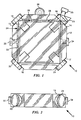
- Figure 1 is a plan view of a ring laser gyroscope showing an insulating ring connected between a ring laser gyroscope frame and a mounting device;
- Figure 2 is a front elevation view of the ring laser gyroscope of Figure 1;
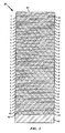
- Figure 3 is a cross-sectional view illustrates a mirror according to the present invention comprising a substrate having a plurality of layers formed thereon; and
- Figure 4 is a cross-sectional view illustrating an ultraviolet-resistive coating formed on a conventional mirror.
- Referring to Figures 1 and 2, a basic
ring laser gyroscope 10 includes aframe 12 that has a generally rectangular shape with the corners cut off to form four mounting faces 14-17. A plurality of mirrors 18-21 are mounted on the mounting faces 14-17, respectively. Acavity 22 is formed in theframe 12 to form a rectangular path around theframe 12 between the mirrors 18-21. Other structures may be used for thering laser gyroscope 10. In particular, the ring laser gyroscope may have a triangular configuration (not shown) with three mirrors, or it may have more than four mirrors. The ring laser gyroscope may be formed to have either a planar optical path or an out of plane optical path. The basic description of thering laser gyroscope 10 is presented by way of example to show utility of the present invention and not for limitation of the present invention to a particular ring laser gyroscope structure. - A gain medium is positioned in the
cavity 22. The gain medium is typically a mixture of helium and neon, which, when electrically excited, producescounterpropagating light beams cavity 22. A plasma discharge is confined to aregion 24 of thecavity 22. Energy is delivered to the gain medium by a power supply (not shown) which applies suitable voltages to a pair ofanodes cathode 36. - A least one of the
mirrors mirror 18, for example, propagate through themirror 18 and into a combiningoptic 23. The combiningoptic 23 may be a prism that by means of internal reflections causes the beams that were perpendicular when they impinged upon the mirror surface in the cavity to emerge parallel and superimposed. The combiningoptic 23 thus causes the clockwise and counterclockwise beams to interfere. The structural features of suitable combining optics are well-known and are not described in greater detail herein. - A
photodetector 25 produces electrical signals indicative of the light intensity in the interference pattern of the two beams. The electrical signals output from thephotodetector 25 may be processed to determine the rotation rate of the device to which the ring laser gyroscope is mounted. - The
mirrors mirrors cavity 22 at a value selected to provide resonance at a wavelength of light emitted by the gain medium. - The present invention is directed to the structures of the mirrors 18-20. Referring to Figure 3, the
mirror 20, for example, includes asubstrate 40 and a plurality of layers of a high refractive index material H and low refractive index material L. The substrate is preferably formed of a glass-ceramic material that is commercially available under the trademark ZERODUR. The ZERODUR glass-ceramic material is used in making ring laser gyroscope frames and mirror substrates. The properties of ZERODUR glass-ceramic material are well-known in the ring laser gyroscope arts. It has a very low coefficient of thermal expansion and therefore experiences very little change in dimension for temperature changes in the operating temperature range of ring laser gyroscopes. - The
substrate 40 has an opticallyflat surface 42 upon which athin layer 44 of the high refractive index material is formed. The thickness of the high refractive index layer preferably is
layer 44 and the direction of the laser beam as it impinges upon thelayer 44. In the present application, the wavelength is 6328Å. The high refractive index material is preferably tantala, Ta₂O₅, which has a refractive index n₁ = 2.05. - A low
refractive index layer 46 is formed on the highrefractive index layer 44. The thickness of the lowrefractive index material 44 is also preferably a quarter wavelength of the laser light. The low index material is preferably formed of alumina Al₂O₃, which has a refractive index n₂ =1.65. The thickness, T, of each layer is equal to
layer 46 and the direction of the laser beam as it impinges upon thelayer 46. - The
mirror 20 preferably has thirty-three layers of the high refractive index Ta₂O₅ that alternate with thirty-three layers of the low refractive index Al₂O₃ arranged to form a stack in the usual manner for forming multilayer mirror coatings. The thirty-third layer 50 of the low index Al₂O₃ has anouter layer 52 of Al₂O₃ formed thereon. Theouter layer 52 of the low index material preferably has a thickness of that is the same as that of the layer 50 and is included in themirror 20 to minimize electric fields in the outer surface of themirror 20. - The
mirror 20 formed as described above has a reflectivity of nearly 100%. Themirror 18, which transmits part of the light incident thereon to the combiningoptic 23 may be formed of alternating layers of Ta₂O₅ and Al₂O₃ arranged in the manner disclosed in U.S. Patent 4,904,083, which issued February 27, 1990 to Lu et al. Lu et al. discloses a multilayer non-quarter wave stack sandwiched between two multilayer quarter wave stacks. One of the quarter wave stacks is formed on a substrate. - Tantala and alumina have significant advantages over other materials in forming ring laser gyroscope mirror coatings. Tantala and alumina have good resistance to degradation under prolonged exposure to UV radiation and do not crystallize when formed in multiple quarter wavelength coatings. Each interface between the layers is a place where scattering could occur. Crystallization causes scattering and is therefore undesirable.
- An additional advantage is obtained because the refractive indices of the tantala and alumina are close together. A small surface irregularity on one layer will track though the stack to subsequent layers added to the stack where a given surface irregularity first appears. Scattered light is characterized as correlated and uncorrelated. Correlated scattering is reinforcement of scattered light from the original irregularity and from subsequent irregularities caused by the original irregularity. Correlated scattering should therefore be minimized. The amount of correlated scattering depends on the ratio

- Many different coating materials have been evaluated. The absorption and birefringence of SiO₂ doped HfO₂ and Al₂O₃ doped coatings have been found to be very stable under exposure to UV radiation. Therefore, HfO₂ is a suitable coating material to be combined with Al₂O₃ to form an Al₂O₃/SiO₂-HfO₂ or Al₂O₃/Al₂O₃-HfO₂ UV/plasma resistive mirror stack. The refractive indices of SiO₂-HfO2 and Al₂O₃ are about 1.95 and 1.65, respectively, which require about thirty-five layers of each material to build a highly reflective mirror. The amount of dopant is selected to prevent crystallization in the HfO₂. In a typical application approximately the SiO₂-HfO₂ layer is about 20% SiO₂ and about 80% HfO₂. When alumina doped hafnia is used as the high index layer and alumina as the low index layer the Al₂O₃-HfO₂ layer is about 5% to 7% Al₂O₃ and 95% to 93% HfO₂.
- Referring to Figure 4, a highly
reflective mirror 70 having the desired property of being durable on exposure to UV radiation may be formed by overcoating a conventional SiO₂/TiO₂ multilayer stack 72 with alternating layers of Al₂O₃/SiO₂-HfO₂ or Al₂O₃/Al₂O₃-HfO₂ This technique permits a reduction of the number of layers required to construct a UV/plasma resistive mirror. Titanium oxide TiO₂ has a refractive index of about 2.32. SiO₂ has a refractive index of about 1.46. For example, three layers of 76, 77, 78 of Ta₂O₅, SiO₂-HfO₂ or Al₂O₃-HfO₂ may be alternated with threelayers stack 72 to achieve high reflectivity and durability upon exposure to UV radiation. Theupper layer 84 is a quarter wave thick coating of Al₂O₃. - The mirrors described herein are suitable for use in a Zeeman ring laser gyroscope (ZLG), a conventional two-mode ring laser gyroscope and in other applications where UV/plasma damage on mirrors may present a problem.
- The structures and methods disclosed herein illustrate the principles of the present invention. The invention may be embodied in other specific forms without departing from its spirit or essential characteristics. The described embodiments are to be considered in all respects as exemplary and illustrative rather than restrictive. Therefore, the appended claims rather than the foregoing description define the scope of the invention. All modifications to the embodiments described herein that come within the meaning and range of equivalence of the claims are embraced within the scope of the invention.
Claims (16)
- A mirror (20) for reflecting a selected frequency of light, characterised by:
a substrate (40);
a first set of layers (44, H) of a first dielectric material having refractive index n₁ that is resistive to physical and chemical changes upon exposure to ultraviolet radiation coated upon the substrate to a thickness equal to one quarter of the wavelength corresponding to the selected frequency in the first dielectric material; and
a second set of layers (46, L) of a second dielectric material having refractive index n₂ that is resistive to physical and chemical changes upon exposure to ultraviolet radiation coated upon the first set of layers to a thickness equal to one quarter of the wavelength corresponding to the selected frequency in the second dielectric material, the layers of the first and second materials being applied alternately to produce a stack of layers (H, L) of the first and second materials. - The mirror (20) of claim 1 wherein the first dielectric material is comprised of tantala, Ta₂O₅ and the second dielectric comprises alumina, Al₂O₃.
- The mirror (20) of claim 1 wherein the first dielectric material is comprised of TiO₂ and the second dielectric comprises Al₂O₃.
- The mirror (20) of claim 1 wherein the first dielectric material is comprised of TiO₂ and the second dielectric comprises SiO₂ and wherein a plurality of layers (50, 52) of a third and fourth dielectric material are added to the stack.
- The mirror (20) of claim 4 wherein the third dielectric material comprises a mixture of SiO₂ and HfO₂ and the fourth dielectric layer comprises Al₂O₃.
- The mirror (20) of claim 5 wherein the third dielectric material is approximately 20% SiO₂ and 80% HfO₂.
- The mirror (20) of claim 4 wherein the third dielectric material comprises a mixture of Al₂O₃ and HfO₂ and the fourth dielectric layer comprises Al₂O₃.
- The mirror (20) of claim 7 wherein the third dielectric layer is 5 to 7 percent Al₂O₃ and 95 to 93 percent HfO₂.
- A method for forming a mirror for reflecting a selected frequency of light, characterised by the steps of:
forming a first set of layers (44, H) of a first dielectric material having refractive index n₁ that is resistive to physical and chemical changes upon exposure to ultraviolet radiation coated on a substrate to a thickness equal to one quarter of the wavelength corresponding to the selected frequency in the first dielectric material; and
forming a second set of layers (46, L) of a second dielectric material having refractive index n₂ that is resistive to physical and chemical changes upon exposure to ultraviolet radiation coated upon the first set of layers to a thickness equal to one quarter of the wavelength corresponding to the selected frequency in the second dielectric material, the layers (H, L) of the first and second materials being applied alternately to produce a stack of layers of the first and second materials. - The method of claim 9 including the steps of forming the first set of layers (44) from a material comprising tantala, Ta₂O₅ and forming the second set of layers (46) from a material comprising alumina, Al₂O₃.
- The method of claim 9 including the steps of forming the first set of layers (44) from a material comprising TiO₂ and forming the second set of layers (46) from a material comprising Al₂O₃.
- The method of claim 9 including the steps of forming the first set of layers (44) from a material comprising TiO₂, forming the second set of layers (46) from a material comprising SiO₂ and adding a plurality of layers (50, 52) of a third and fourth dielectric material to the stack.
- The method of claim 12 including the steps of forming the third dielectric material from a material comprising a mixture of SiO₂ and HfO₂ and forming the fourth dielectric material from a material comprising Al₂O₃.
- The method of claim 13 including the step of the third dielectric material to be approximately 20% SiO₂ and 80% HfO₂.
- The method of claim 12 including the steps of forming the third dielectric material to comprise a mixture of Al₂O₃ and HfO₂ and forming the fourth dielectric layer to comprise Al₂O₃.
- The mirror of claim 15 including the step of forming the third dielectric layer to be between 5 to 7 percent Al₂O₃ and between 95 to 93 percent HfO₂.
Applications Claiming Priority (2)
| Application Number | Priority Date | Filing Date | Title |
|---|---|---|---|
| US08/067,385 US5513039A (en) | 1993-05-26 | 1993-05-26 | Ultraviolet resistive coated mirror and method of fabrication |
| US67385 | 1998-04-27 |
Publications (2)
| Publication Number | Publication Date |
|---|---|
| EP0626597A1 true EP0626597A1 (en) | 1994-11-30 |
| EP0626597B1 EP0626597B1 (en) | 1998-11-11 |
Family
ID=22075657
Family Applications (1)
| Application Number | Title | Priority Date | Filing Date |
|---|---|---|---|
| EP94303685A Expired - Lifetime EP0626597B1 (en) | 1993-05-26 | 1994-05-23 | Ultraviolet resistive coated mirror and method of fabrication |
Country Status (4)
| Country | Link |
|---|---|
| US (1) | US5513039A (en) |
| EP (1) | EP0626597B1 (en) |
| JP (1) | JP2627864B2 (en) |
| DE (1) | DE69414458T2 (en) |
Cited By (6)
| Publication number | Priority date | Publication date | Assignee | Title |
|---|---|---|---|---|
| GB2352050A (en) * | 1999-07-13 | 2001-01-17 | Coherent Optics | Interference filters |
| EP1227358A3 (en) * | 2001-01-25 | 2004-03-31 | Canon Kabushiki Kaisha | Optical element and liquid crystal projector and camera using the same |
| FR2987139A1 (en) * | 2012-02-21 | 2013-08-23 | Commissariat Energie Atomique | OPTICAL DEVICE FOR REFLECTING DIFFRACTION HAVING A HIGH LASER FLOW. |
| EP3557291A1 (en) * | 2018-04-18 | 2019-10-23 | Honeywell International Inc. | Methods for enhancing the durability and manufacturability of multilayer interference mirrors |
| US20220131333A1 (en) * | 2020-10-27 | 2022-04-28 | Honeywell International Inc. | Ultraviolet filter for ring laser gyroscope mirrors |
| US11385057B2 (en) * | 2019-09-20 | 2022-07-12 | Honeywell International Inc. | Extra thick ultraviolet durability coating |
Families Citing this family (25)
| Publication number | Priority date | Publication date | Assignee | Title |
|---|---|---|---|---|
| US5911858A (en) * | 1997-02-18 | 1999-06-15 | Sandia Corporation | Method for high-precision multi-layered thin film deposition for deep and extreme ultraviolet mirrors |
| US6262830B1 (en) | 1997-09-16 | 2001-07-17 | Michael Scalora | Transparent metallo-dielectric photonic band gap structure |
| US5907427A (en) | 1997-10-24 | 1999-05-25 | Time Domain Corporation | Photonic band gap device and method using a periodicity defect region to increase photonic signal delay |
| US6304366B1 (en) | 1998-04-02 | 2001-10-16 | Michael Scalora | Photonic signal frequency conversion using a photonic band gap structure |
| US6744552B2 (en) * | 1998-04-02 | 2004-06-01 | Michael Scalora | Photonic signal frequency up and down-conversion using a photonic band gap structure |
| DE19815065A1 (en) * | 1998-04-03 | 1999-10-14 | Trumpf Lasertechnik Gmbh | HF-excited gas laser and laser tube for such a gas laser |
| US5914817A (en) * | 1998-05-15 | 1999-06-22 | Optical Coating Laboratory, Inc. | Thin film dichroic color separation filters for color splitters in liquid crystal display systems |
| US6356020B1 (en) * | 1998-07-06 | 2002-03-12 | U.S. Philips Corporation | Electric lamp with optical interference coating |
| US6396617B1 (en) | 1999-05-17 | 2002-05-28 | Michael Scalora | Photonic band gap device and method using a periodicity defect region doped with a gain medium to increase photonic signal delay |
| TWI267704B (en) * | 1999-07-02 | 2006-12-01 | Asml Netherlands Bv | Capping layer for EUV optical elements |
| US6538794B1 (en) | 1999-09-30 | 2003-03-25 | D'aguanno Giuseppe | Efficient non-linear phase shifting using a photonic band gap structure |
| US6339493B1 (en) | 1999-12-23 | 2002-01-15 | Michael Scalora | Apparatus and method for controlling optics propagation based on a transparent metal stack |
| US6414780B1 (en) | 1999-12-23 | 2002-07-02 | D'aguanno Giuseppe | Photonic signal reflectivity and transmissivity control using a photonic band gap structure |
| JP2003015175A (en) | 2001-04-27 | 2003-01-15 | Mitsubishi Electric Corp | Solid-state light source device |
| US20030064161A1 (en) * | 2001-06-06 | 2003-04-03 | Malinowski Michael E. | Method for reducing carbon contamination of multilayer mirrors |
| WO2006017311A1 (en) | 2004-07-12 | 2006-02-16 | Cardinal Cg Company | Low-maintenance coatings |
| EP2013150B1 (en) | 2006-04-11 | 2018-02-28 | Cardinal CG Company | Photocatalytic coatings having improved low-maintenance properties |
| US20080011599A1 (en) | 2006-07-12 | 2008-01-17 | Brabender Dennis M | Sputtering apparatus including novel target mounting and/or control |
| US7820309B2 (en) | 2007-09-14 | 2010-10-26 | Cardinal Cg Company | Low-maintenance coatings, and methods for producing low-maintenance coatings |
| JP4976346B2 (en) * | 2008-07-16 | 2012-07-18 | 日本航空電子工業株式会社 | Visible light mirror, visible light oscillation gas laser, and He-Ne ring laser gyro |
| US20100102698A1 (en) * | 2008-10-23 | 2010-04-29 | Zhibo Zhao | High refractive index materials for energy efficient lamps |
| KR101707187B1 (en) | 2016-07-29 | 2017-02-15 | 한화디펜스 주식회사 | Mirror of a ring laser gyroscope |
| EP3541762B1 (en) | 2016-11-17 | 2022-03-02 | Cardinal CG Company | Static-dissipative coating technology |
| US10739137B2 (en) | 2018-08-17 | 2020-08-11 | Honeywell International Inc. | Solid state ring laser gyroscope using rare-earth gain dopants in glassy hosts |
| US20200056889A1 (en) * | 2018-08-17 | 2020-02-20 | Honeywell International Inc. | Enhanced solid-state gain medium for ring laser gyroscopes |
Citations (4)
| Publication number | Priority date | Publication date | Assignee | Title |
|---|---|---|---|---|
| WO1989002607A2 (en) * | 1987-09-11 | 1989-03-23 | Litton Systems Inc. | Partly transparent mirror for a ring laser gyro |
| EP0372438A2 (en) * | 1988-12-05 | 1990-06-13 | Honeywell Inc. | UV and plasma stable high-reflectance multilayer dielectric mirror |
| EP0379738A2 (en) * | 1989-01-23 | 1990-08-01 | Balzers Aktiengesellschaft | Optical layer |
| DE4117256A1 (en) * | 1989-12-19 | 1992-12-03 | Leybold Ag | Antireflective coating for optical glass etc. - comprising multilayer oxide system with controlled refractive indices |
Family Cites Families (39)
| Publication number | Priority date | Publication date | Assignee | Title |
|---|---|---|---|---|
| US3528726A (en) * | 1969-07-10 | 1970-09-15 | Perkin Elmer Corp | Narrow band interference light filter |
| US3741657A (en) * | 1971-03-03 | 1973-06-26 | Raytheon Co | Laser gyroscope |
| CH564785A5 (en) * | 1972-12-08 | 1975-07-31 | Balzers Patent Beteilig Ag | |
| US4063803A (en) * | 1976-06-03 | 1977-12-20 | Spectra-Physics, Inc. | Transmissive end seal for laser tubes |
| USRE32849E (en) * | 1978-04-13 | 1989-01-31 | Litton Systems, Inc. | Method for fabricating multi-layer optical films |
| JPS6038681B2 (en) * | 1978-09-27 | 1985-09-02 | キヤノン株式会社 | Ultraviolet multilayer film |
| US4213705A (en) * | 1978-11-09 | 1980-07-22 | Litton Systems, Inc. | Four mode Zeeman laser gyroscope with minimum hole burning competition |
| JPS57181503A (en) * | 1981-04-30 | 1982-11-09 | Nippon Soken Inc | Heat ray reflecting film |
| US4663557A (en) * | 1981-07-20 | 1987-05-05 | Optical Coating Laboratory, Inc. | Optical coatings for high temperature applications |
| JPS5890604A (en) * | 1981-11-25 | 1983-05-30 | Toyota Central Res & Dev Lab Inc | Infrared shielding laminate |
| CH651998GA3 (en) * | 1983-07-08 | 1985-10-31 | ||
| DD219882A1 (en) * | 1983-08-08 | 1985-03-13 | Univ Schiller Jena | OPTICAL VARIETY SYSTEM |
| US4685110A (en) * | 1984-09-24 | 1987-08-04 | Spectra-Physics, Inc. | Optical component of a laser |
| US4583822A (en) * | 1984-10-31 | 1986-04-22 | Rockwell International Corporation | Quintic refractive index profile antireflection coatings |
| US4666250A (en) * | 1985-04-16 | 1987-05-19 | Rockwell International Corporation | Interference filter design using flip-flop optimization |
| US4809293A (en) * | 1985-09-03 | 1989-02-28 | Spectra-Physics, Inc. | Optical component of a laser |
| JPS6346404A (en) * | 1986-08-14 | 1988-02-27 | Toshiba Corp | Beam splitter |
| US4854670A (en) * | 1986-12-17 | 1989-08-08 | Gte Products Corporation | Wide angle optical filters |
| US4793908A (en) * | 1986-12-29 | 1988-12-27 | Rockwell International Corporation | Multiple ion source method and apparatus for fabricating multilayer optical films |
| US4934788A (en) * | 1987-03-20 | 1990-06-19 | Rockwell International Corporation | Deposition of gradient index coatings using coevaporation with rate control |
| US4904083A (en) * | 1987-09-11 | 1990-02-27 | Litton Systems, Inc. | Partially transparent mirror for a ring laser |
| US4827870A (en) * | 1987-10-05 | 1989-05-09 | Honeywell Inc. | Apparatus for applying multilayer optical interference coating on complex curved substrates |
| US4907846A (en) * | 1987-11-20 | 1990-03-13 | Raytheon Company | Thick, impact resistant antireflection coatings for IR transparent optical elements |
| JPH01154001A (en) * | 1987-12-10 | 1989-06-16 | Minolta Camera Co Ltd | Optical filter |
| US4966437A (en) * | 1988-04-19 | 1990-10-30 | Litton Systems, Inc. | Fault-tolerant anti-reflective coatings |
| US4925259A (en) * | 1988-10-20 | 1990-05-15 | The United States Of America As Represented By The United States Department Of Energy | Multilayer optical dielectric coating |
| DE3902144A1 (en) * | 1989-01-25 | 1990-08-02 | Heraeus Gmbh W C | DEUTERIUM LAMP FOR SPECTRAL ANALYSIS DEVICES |
| JPH0312605A (en) * | 1989-06-09 | 1991-01-21 | Topcon Corp | Multi-layered film mirror reflecting two-wavelength of ultraviolet-light and visible-light |
| JPH03156838A (en) * | 1989-07-05 | 1991-07-04 | Nippon Sheet Glass Co Ltd | Cathode-ray tube faceplate |
| DE4024308C2 (en) * | 1989-07-31 | 1993-12-02 | Central Glass Co Ltd | Thermal insulating glass with dielectric multilayer coating |
| DE3941859C1 (en) * | 1989-12-19 | 1991-01-24 | Deutsche Spezialglas Ag, 3223 Gruenenplan, De | |
| US5170291A (en) * | 1989-12-19 | 1992-12-08 | Leybold Aktiengesellschaft | Coating, composed of an optically effective layer system, for substrates, whereby the layer system has a high anti-reflective effect, and method for manufacturing the coating |
| JP2902729B2 (en) * | 1990-05-29 | 1999-06-07 | 日本真空光学株式会社 | Manufacturing method of dielectric multilayer film |
| JPH0792527B2 (en) * | 1991-02-01 | 1995-10-09 | 岡本硝子株式会社 | Reflector |
| JPH04340905A (en) * | 1991-05-17 | 1992-11-27 | Tokyo Tokushu Glass Kk | Surface reflection mirror |
| US5318830A (en) * | 1991-05-29 | 1994-06-07 | Central Glass Company, Limited | Glass pane with reflectance reducing coating |
| GB2261079B (en) * | 1991-10-31 | 1995-06-14 | Asahi Optical Co Ltd | Surface reflecting mirror |
| US5400179A (en) * | 1992-02-18 | 1995-03-21 | Asahi Kogaku Kogyo Kabushiki Kaisha | Optical multilayer thin film and beam splitter |
| US5254202A (en) * | 1992-04-07 | 1993-10-19 | International Business Machines Corporation | Fabrication of laser ablation masks by wet etching |
-
1993
- 1993-05-26 US US08/067,385 patent/US5513039A/en not_active Expired - Lifetime
-
1994
- 1994-05-23 EP EP94303685A patent/EP0626597B1/en not_active Expired - Lifetime
- 1994-05-23 DE DE69414458T patent/DE69414458T2/en not_active Expired - Fee Related
- 1994-05-25 JP JP6110702A patent/JP2627864B2/en not_active Expired - Fee Related
Patent Citations (4)
| Publication number | Priority date | Publication date | Assignee | Title |
|---|---|---|---|---|
| WO1989002607A2 (en) * | 1987-09-11 | 1989-03-23 | Litton Systems Inc. | Partly transparent mirror for a ring laser gyro |
| EP0372438A2 (en) * | 1988-12-05 | 1990-06-13 | Honeywell Inc. | UV and plasma stable high-reflectance multilayer dielectric mirror |
| EP0379738A2 (en) * | 1989-01-23 | 1990-08-01 | Balzers Aktiengesellschaft | Optical layer |
| DE4117256A1 (en) * | 1989-12-19 | 1992-12-03 | Leybold Ag | Antireflective coating for optical glass etc. - comprising multilayer oxide system with controlled refractive indices |
Cited By (10)
| Publication number | Priority date | Publication date | Assignee | Title |
|---|---|---|---|---|
| GB2352050A (en) * | 1999-07-13 | 2001-01-17 | Coherent Optics | Interference filters |
| EP1227358A3 (en) * | 2001-01-25 | 2004-03-31 | Canon Kabushiki Kaisha | Optical element and liquid crystal projector and camera using the same |
| FR2987139A1 (en) * | 2012-02-21 | 2013-08-23 | Commissariat Energie Atomique | OPTICAL DEVICE FOR REFLECTING DIFFRACTION HAVING A HIGH LASER FLOW. |
| WO2013124289A1 (en) * | 2012-02-21 | 2013-08-29 | Commissariat à l'énergie atomique et aux énergies alternatives | Optical reflective diffraction device having a high resistance to laser flux |
| US9671534B2 (en) | 2012-02-21 | 2017-06-06 | Commissariat A L'energie Atomique Et Aux Energies Alternatives | Optical reflective diffraction device having a high resistance to laser flux |
| EP3557291A1 (en) * | 2018-04-18 | 2019-10-23 | Honeywell International Inc. | Methods for enhancing the durability and manufacturability of multilayer interference mirrors |
| US11385057B2 (en) * | 2019-09-20 | 2022-07-12 | Honeywell International Inc. | Extra thick ultraviolet durability coating |
| US20220131333A1 (en) * | 2020-10-27 | 2022-04-28 | Honeywell International Inc. | Ultraviolet filter for ring laser gyroscope mirrors |
| EP4006594A1 (en) * | 2020-10-27 | 2022-06-01 | Honeywell International Inc. | Ultraviolet filter for ring laser gyroscope mirrors |
| US11962118B2 (en) * | 2020-10-27 | 2024-04-16 | Honeywell International Inc. | Ultraviolet filter for ring laser gyroscope mirrors |
Also Published As
| Publication number | Publication date |
|---|---|
| DE69414458T2 (en) | 1999-06-24 |
| EP0626597B1 (en) | 1998-11-11 |
| US5513039A (en) | 1996-04-30 |
| JP2627864B2 (en) | 1997-07-09 |
| DE69414458D1 (en) | 1998-12-17 |
| JPH0772330A (en) | 1995-03-17 |
Similar Documents
| Publication | Publication Date | Title |
|---|---|---|
| US5513039A (en) | Ultraviolet resistive coated mirror and method of fabrication | |
| US4615034A (en) | Ultra-narrow bandwidth optical thin film interference coatings for single wavelength lasers | |
| EP0280299B1 (en) | Reflector for excimer laser and excimer laser apparatus using the reflector | |
| US4525028A (en) | Enhanced magnetic mirror | |
| Lowdermilk et al. | Optical coatings for laser fusion applications | |
| EP0626596B1 (en) | Ultraviolet resistive antireflective coating | |
| US4627732A (en) | Mode discrimination apparatus | |
| EP0615319B1 (en) | Quasi-monolithic saturable optical element | |
| JPS6037631B2 (en) | Argon ion laser device | |
| JPH0117275B2 (en) | ||
| US4685110A (en) | Optical component of a laser | |
| EP0267672A2 (en) | Mirrors of polarization sensitive reflectivity | |
| US5608577A (en) | Optical mirror and optical device using the same | |
| US4809293A (en) | Optical component of a laser | |
| US4904083A (en) | Partially transparent mirror for a ring laser | |
| US4800568A (en) | Gas laser with a frequency-selective dielectric layer system | |
| EP0402429A1 (en) | Multilayer optical dielectric coating | |
| US4340969A (en) | Laser apparatus | |
| Callahan et al. | Characteristics of deep-UV optics at 193 nm and 157 nm | |
| EP0628158A1 (en) | Laser intensity monitoring apparatus with metallic thin film mask | |
| JPH07107561B2 (en) | Multilayer optics | |
| EP0370071B1 (en) | Partly transparent mirror for a ring laser gyro | |
| Ahmed et al. | Polarizing grating coupler for high Q laser cavities | |
| JP2002261359A (en) | Thin film laser device | |
| KR100287113B1 (en) | Nd:yvo4 crystalline antireflection film for second harmonic generation |
Legal Events
| Date | Code | Title | Description |
|---|---|---|---|
| PUAI | Public reference made under article 153(3) epc to a published international application that has entered the european phase |
Free format text: ORIGINAL CODE: 0009012 |
|
| AK | Designated contracting states |
Kind code of ref document: A1 Designated state(s): CH DE FR GB LI |
|
| 17P | Request for examination filed |
Effective date: 19950512 |
|
| 17Q | First examination report despatched |
Effective date: 19961128 |
|
| GRAG | Despatch of communication of intention to grant |
Free format text: ORIGINAL CODE: EPIDOS AGRA |
|
| GRAG | Despatch of communication of intention to grant |
Free format text: ORIGINAL CODE: EPIDOS AGRA |
|
| GRAH | Despatch of communication of intention to grant a patent |
Free format text: ORIGINAL CODE: EPIDOS IGRA |
|
| GRAH | Despatch of communication of intention to grant a patent |
Free format text: ORIGINAL CODE: EPIDOS IGRA |
|
| GRAA | (expected) grant |
Free format text: ORIGINAL CODE: 0009210 |
|
| AK | Designated contracting states |
Kind code of ref document: B1 Designated state(s): CH DE FR GB LI |
|
| REG | Reference to a national code |
Ref country code: CH Ref legal event code: EP |
|
| REF | Corresponds to: |
Ref document number: 69414458 Country of ref document: DE Date of ref document: 19981217 |
|
| ET | Fr: translation filed | ||
| REG | Reference to a national code |
Ref country code: CH Ref legal event code: NV Representative=s name: CABINET ROLAND NITHARDT CONSEILS EN PROPRIETE INDU |
|
| PGFP | Annual fee paid to national office [announced via postgrant information from national office to epo] |
Ref country code: CH Payment date: 19990526 Year of fee payment: 6 |
|
| PLBE | No opposition filed within time limit |
Free format text: ORIGINAL CODE: 0009261 |
|
| STAA | Information on the status of an ep patent application or granted ep patent |
Free format text: STATUS: NO OPPOSITION FILED WITHIN TIME LIMIT |
|
| 26N | No opposition filed | ||
| PG25 | Lapsed in a contracting state [announced via postgrant information from national office to epo] |
Ref country code: LI Free format text: LAPSE BECAUSE OF NON-PAYMENT OF DUE FEES Effective date: 20000531 Ref country code: CH Free format text: LAPSE BECAUSE OF NON-PAYMENT OF DUE FEES Effective date: 20000531 |
|
| REG | Reference to a national code |
Ref country code: CH Ref legal event code: PL |
|
| REG | Reference to a national code |
Ref country code: GB Ref legal event code: IF02 |
|
| PGFP | Annual fee paid to national office [announced via postgrant information from national office to epo] |
Ref country code: DE Payment date: 20070702 Year of fee payment: 14 |
|
| PG25 | Lapsed in a contracting state [announced via postgrant information from national office to epo] |
Ref country code: DE Free format text: LAPSE BECAUSE OF NON-PAYMENT OF DUE FEES Effective date: 20081202 |
|
| PGFP | Annual fee paid to national office [announced via postgrant information from national office to epo] |
Ref country code: GB Payment date: 20110520 Year of fee payment: 18 |
|
| GBPC | Gb: european patent ceased through non-payment of renewal fee |
Effective date: 20120523 |
|
| PG25 | Lapsed in a contracting state [announced via postgrant information from national office to epo] |
Ref country code: GB Free format text: LAPSE BECAUSE OF NON-PAYMENT OF DUE FEES Effective date: 20120523 |
|
| PGFP | Annual fee paid to national office [announced via postgrant information from national office to epo] |
Ref country code: FR Payment date: 20130603 Year of fee payment: 20 |