EP0626206B1 - Adapter for centrifuge tube - Google Patents
Adapter for centrifuge tube Download PDFInfo
- Publication number
- EP0626206B1 EP0626206B1 EP94107533A EP94107533A EP0626206B1 EP 0626206 B1 EP0626206 B1 EP 0626206B1 EP 94107533 A EP94107533 A EP 94107533A EP 94107533 A EP94107533 A EP 94107533A EP 0626206 B1 EP0626206 B1 EP 0626206B1
- Authority
- EP
- European Patent Office
- Prior art keywords
- adapter
- tube
- inboard
- segment
- opening
- Prior art date
- Legal status (The legal status is an assumption and is not a legal conclusion. Google has not performed a legal analysis and makes no representation as to the accuracy of the status listed.)
- Expired - Lifetime
Links
- 239000000463 material Substances 0.000 claims description 34
- 239000003566 sealing material Substances 0.000 claims description 8
- 238000007373 indentation Methods 0.000 claims description 5
- 238000005119 centrifugation Methods 0.000 description 18
- 239000007788 liquid Substances 0.000 description 11
- 238000000034 method Methods 0.000 description 5
- ZMMJGEGLRURXTF-UHFFFAOYSA-N ethidium bromide Chemical compound [Br-].C12=CC(N)=CC=C2C2=CC=C(N)C=C2[N+](CC)=C1C1=CC=CC=C1 ZMMJGEGLRURXTF-UHFFFAOYSA-N 0.000 description 3
- 229960005542 ethidium bromide Drugs 0.000 description 3
- 230000002706 hydrostatic effect Effects 0.000 description 3
- 230000001419 dependent effect Effects 0.000 description 2
- 238000001738 isopycnic centrifugation Methods 0.000 description 2
- 239000003471 mutagenic agent Substances 0.000 description 2
- 231100000707 mutagenic chemical Toxicity 0.000 description 2
- 230000003505 mutagenic effect Effects 0.000 description 2
- 239000004033 plastic Substances 0.000 description 2
- 229920000049 Carbon (fiber) Polymers 0.000 description 1
- 239000004954 Polyphthalamide Substances 0.000 description 1
- 230000004323 axial length Effects 0.000 description 1
- 230000015572 biosynthetic process Effects 0.000 description 1
- 239000004917 carbon fiber Substances 0.000 description 1
- 125000004122 cyclic group Chemical group 0.000 description 1
- 230000000994 depressogenic effect Effects 0.000 description 1
- 239000013536 elastomeric material Substances 0.000 description 1
- 230000000415 inactivating effect Effects 0.000 description 1
- 238000002347 injection Methods 0.000 description 1
- 239000007924 injection Substances 0.000 description 1
- 238000001746 injection moulding Methods 0.000 description 1
- 238000007689 inspection Methods 0.000 description 1
- 238000004519 manufacturing process Methods 0.000 description 1
- 230000013011 mating Effects 0.000 description 1
- VNWKTOKETHGBQD-UHFFFAOYSA-N methane Chemical compound C VNWKTOKETHGBQD-UHFFFAOYSA-N 0.000 description 1
- 239000004417 polycarbonate Substances 0.000 description 1
- 229920000515 polycarbonate Polymers 0.000 description 1
- 229920006375 polyphtalamide Polymers 0.000 description 1
- 238000007789 sealing Methods 0.000 description 1
- 238000000926 separation method Methods 0.000 description 1
- 238000004513 sizing Methods 0.000 description 1
- 238000009987 spinning Methods 0.000 description 1
- 238000013022 venting Methods 0.000 description 1
- 230000000007 visual effect Effects 0.000 description 1
Images



Classifications
-
- B—PERFORMING OPERATIONS; TRANSPORTING
- B04—CENTRIFUGAL APPARATUS OR MACHINES FOR CARRYING-OUT PHYSICAL OR CHEMICAL PROCESSES
- B04B—CENTRIFUGES
- B04B5/00—Other centrifuges
- B04B5/04—Radial chamber apparatus for separating predominantly liquid mixtures, e.g. butyrometers
- B04B5/0407—Radial chamber apparatus for separating predominantly liquid mixtures, e.g. butyrometers for liquids contained in receptacles
- B04B5/0414—Radial chamber apparatus for separating predominantly liquid mixtures, e.g. butyrometers for liquids contained in receptacles comprising test tubes
-
- B—PERFORMING OPERATIONS; TRANSPORTING
- B04—CENTRIFUGAL APPARATUS OR MACHINES FOR CARRYING-OUT PHYSICAL OR CHEMICAL PROCESSES
- B04B—CENTRIFUGES
- B04B5/00—Other centrifuges
- B04B5/04—Radial chamber apparatus for separating predominantly liquid mixtures, e.g. butyrometers
- B04B5/0407—Radial chamber apparatus for separating predominantly liquid mixtures, e.g. butyrometers for liquids contained in receptacles
- B04B2005/0435—Radial chamber apparatus for separating predominantly liquid mixtures, e.g. butyrometers for liquids contained in receptacles with adapters for centrifuge tubes or bags
Definitions
- the present invention relates to a cartridge adapter for a centrifuge tube.
- PCT publication WO 91/06373 discloses a cartridge adapter for supporting a sealed centrifuge tube within a cavity of a centrifuge rotor.
- the cartridge adapter comprises a pair of matable adapter segments, each of which has an indentation therein. When the segments are joined along mating surfaces the indentation in each segment cooperate to define a recess having a size and shape that closely corresponds (within a certain range of manufacturing tolerances) to the size and shape of some portion or all of the sealed centrifuge tube.
- the inboard segment A i lies radially closer to the axis of rotation VCL.
- the inboard segment A i has a keying feature thereon which identifies it as the segment that is introduced into the radially inboard side of the cavity C.
- the other segment termed the radially outboard segment A o , lies radially outwardly of the inboard segment and radially further from the axis of rotation VCL.
- Figures 1A and 1B are top sectional views, taken in a plane transverse to the longitudinal axis of a prior art sealed plastic centrifuge tube T illustrating the inboard and outboard segments A i , A o , respectively, of a cartridge adapter as they support the tube T within a cavity C of a rotor V, illustrated as a vertical angle rotor.
- the inside surfaces of the respective inboard and outboard segments A i and A o of the adapter lie (within dimensional tolerances) close to or in physical contact with the exterior surface of the sealed tube about its entire circumference. It is noted that the inside surfaces of the adapter segments lie in this disposition with respect to the tube throughout the tube's entire axial length. That is, for each transverse section along the longitudinal axis of the tube, the relationship shown in Figure 1A is maintained.
- this portion P 1 of the tube is spaced from, or defines a clearance with, the adjacent region R of the inner surface of the inboard segment A i .
- This spacing is indicated by the character S in Figure 1B, while the region R of the inboard segment A i is indicated by the dot-dash arc.
- the radial magnitude of the spacing S is dependent upon both the volume, the compressibility of the liquid within the sealed tube, and, in some instances, the fit of the tube T into the adapter.
- the vector sum of the forces F c and F h is such that the exterior of the tube T is forced into intimate contacting relationship with the inner surface of the inboard and outboard segments A i and A o of the adapter lying adjacent thereto.
- the region of intimate contact is indicated by the relatively heavy line of contact.
- the depression D formed as described has a length dimension measured along the longitudinal axis of the tube. The magnitude of this length dimension is also dependent upon both the volume and the compressibility of the liquid within the tube. If, for example, a tube were completely filled with an incompressible liquid, the force of the liquid would balance the centrifugal force and the depression would likely not form. Since, in practice, the tube is seldom totally filled and liquids are compressible to some extent, a depression D is likely to form along some portion of the length of the radially inward portion of the tube T.
- the depression may be envisioned as a dimple in the radially inward portion of the tube.
- the hydrostatic force of the liquid within the tube T is not able to provide any support for this region of the inboard segment A i .
- the hydrostatic force of the liquid within the tube T does, however, provide some support to that region of the inboard segment A i into which the tube T has been forced into intimate contacting relationship.
- the unsupported region R of the inboard segment of the adapter is deflected radially outwardly.
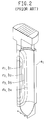
- the magnitude of the deflection is illustrated in Figure 2 by surface contours of constant deflection or stress.
- Figure 2 is a vertical perspective taken along a vertical central plane through one half of the inboard segment A i it should be understood that the surface contours shown in Figure 2 are symmetric about the vertical central plane.
- the magnitude of the relative deflections of the region R of the inboard segment A i of the adapter are indicated by the characters ⁇ 1 through ⁇ 4 . Since relatively greater deflections produce relatively greater stresses in the adapter segment the surface contours indicating the relative magnitude of the attendant stresses are similar in form to the surface contours of the deflection.
- the stress contours are thus shown in Figure 2 and are indicated by the characters ⁇ 1 through ⁇ 4 , respectively.
- the character ⁇ 1 and the character ⁇ 1 indicate the greatest magnitude of deflection or stress, as the case may be. Those areas of the inboard segment A i experiencing higher deflections and higher stresses are more likely to fail.
- WO-A-92/19382 discloses an adapter for holding a centrifuge tube in a centrifuge rotor cavity comprising two segments which may be hinged along a hinge axis that extends perpendicular to the axis of the adapter.
- the inboard segment is subjected to deflections and stress as set out above.
- centrifuge tube adapter having two segments is disclosed in WO-A-86/05718.
- the two segments are hinged along the lateral edges of the segments.
- the hinge axis lies in parallel relationship to the axis of the cavity in which the adapter is received. No efforts are made to reduce deflection and stress of the inboard segment of the adapter.
- DE 35 12 848 discloses a centrifuge of the swinging bucket type having buckets to receive centrifuge tubes which will swing upon centrifugation from a vertical to a horizontal position. Each bucket has a window located on the outboard portion of the bucket to allow inspection of the content of a transparent centrifuge tube.
- equilibrium centrifugation it is common practice in molecular biology applications to utilize a technique termed "equilibrium centrifugation" to isolate various materials in a sample in accordance with their respective density.
- ethidium bromide a mutagen
- the materials After centrifugation, with the tube at rest and upright, the materials reorient to form transverse bands at longitudinally spaced locations along the axis of the tube.
- the ethidium bromide when exposed to ultraviolet light absorbs the ultraviolet light and emits a visible fluorescent light which facilitates location of the band having the material of interest.
- One prevalent method to withdraw a band having a material of interest is to hold the tube in a position so that ultraviolet light can shine therethrough to locate the band.
- the tube may be held by hand or clamped to a stand.
- a vent needle is inserted into the tube above that band (usually near to the top of the tube).
- the operator must steady the tube (whether or not it is clamped) while a syringe is then inserted into the tube.
- the syringe is inserted such that the tip thereof lies immediately beneath the band of material of interest enabling that band to be withdrawn. This process is repeated for each band having a material of interest.
- a first embodiment of the present invention is directed to an adapter for use in a fixed angle centrifuge rotor, the adapter having, while being spun, a portion that lies radially inboard and an portion that lies outboard with respect to an axis of rotation.
- the adapter has a recess sized to receive a centrifuge tube. The tube is exposed, during centrifugation, to a load that causes a first portion of the tube to deflect radially outwardly from a first region of the inboard portion of the adapter while a second, adjacent, portion of the tube is forced into intimate contact with a second region of the inboard portion of the adapter.
- the improvement in the adapter comprises an opening formed in the radially inboard portion of the adapter.
- the opening is substantially coextensive with the first region of the inboard portion of the adapter.
- the opening substantially no part of the inboard portion of the adapter is exposed during centrifugation to a load that exceeds the ability of the material of the adapter to support itself.
- the material of the inboard portion of the adapter surrounding the opening has sufficient strength to support itself while under centrifugation.
- This aspect of the invention may be used with any form of adapter, whether it is integral or segmented.
- the adapter is formed from matable inboard and outboard segments A i , A o , respectively, the opening is provided in the inboard segment A i .
- the adapter includes a plug that is slidably disposed and selectably positionable within the opening in the inboard segment of the adapter.
- the plug has an inside and an outside surface thereon.
- the inside surface of the plug has a sealing material thereon.
- the sealing material is biased into contact with a tube carried within the adapter.
- the opening is large enough to allow the sample to be exposed to an ultraviolet light source and to enable the band to be visually located.
- the adapter may be fabricated from a material transmissive to visible light, so that a band exposed to ultraviolet light through the opening may be visually located through the adapter.
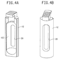
- FIGS. 3, 4A and 4B respectively shown are various perspective views of an adapter generally indicated by the reference character 10 in accordance with the first embodiment the present invention.
- the adapter 10 is used to adapt tubes T for centrifugation in a fixed angle centrifuge rotor V.
- the rotor V has cavities C therein. Each cavity may have a notch N therein.
- the adapter 10 has an inboard segment 12 and an outboard segment 14.
- the inboard segment 12 may have a keying feature 12K thereon which is received in the notch N.
- Both segments 12 and 14 have an indentation 12I, 14I therein.
- the segments 12 and 14 of the adapter 10 are in the preferred case fabricated, as by injection molding, from a material such as thirty percent carbon fiber reinforced polyphthalamide such as that sold by RTP Company, Winona, Minnesota under product number RTP 4085.
- the adapter 10 may be injection molded from a polycarbonate plastic material.
- fixed angle centrifuge rotor means a rotor of the type having cavities formed in the body thereof so that, when a tube is received therein the axis A t of each tube is inclined at a predetermined angular inclination with respect to the axis of rotation VCL and remains in that inclination throughout the centrifugation run.
- a "fixed angle centrifuge rotor” is to be distinguished from a so-called “swinging bucket centrifuge rotor” in which the inclination of the tube with respect to the axis of rotation is initially at approximately zero degrees and which, under centrifugation, swings to an orientation in which the axis of the tube is substantially perpendicular to the axis of rotation.
- the angular inclination of the axis A t of the tube may be produced by inclining the axis A c of the cavity C in the rotor with respect to the axis of rotation VCL, and/or by inclining the axis A r of the recess 16 in the adapter 10. Any angular value including zero degrees (a so-called “vertical rotor") may be used.
- the tube is exposed, during centrifugation, to a load that causes a first portion of the tube to deflect radially outwardly from a first region of the inboard segment 12 of the adapter (corresponding to the region R as discussed above), while a second, adjacent, portion of the tube is forced into intimate contact with a second region of the inboard segment of the adapter.
- the inboard segment 12 has an opening 20 therein.
- the opening 20 is substantially coextensive with the first region first of the inboard segment 12.
- the opening 20 is sized so that substantially no portion of the inboard segment 12 of the adapter is exposed under centrifugation to a load that exceeds the ability of the material of the adapter to support itself.
- the opening 20 is sized so that the material of the inboard segment 12 of the adapter surrounding the opening 20 has sufficient strength to support itself while under centrifugation.
- the term "sufficient strength to support itself” means that the adapter 10 is not likely to fail when used at a predetermined maximum operating speed over a predetermined useful lifetime of cyclic operation.
- substantially coextensive as used throughout this application is meant to encompass an instance in which either more than or less than the entire first region of the inboard segment of the tube is removed. The intent is that by making the opening substantially coextensive with the first region of the inboard segment 12, the areas of relatively higher deflections and higher stresses are either eliminated or substantially reduced.
- the invention has been heretofore described in the context of an adapter formed of matable segments as described in PCT publication WO 91/06373, the invention may be used with equal utility with an adapter that is integrally formed and which, in use, has a portion thereof that is radially inboard with respect to the axis of rotation and a portion that lies radially outboard with respect to the axis of rotation.
- the opening is provided in the radially inboard portion of such an integrally formed adapter.
- the opening is sized as discussed, so that the material of the inboard portion of the adapter surrounding the opening has sufficient strength to support itself while under centrifugation and so that no portion of the adapter is exposed under centrifugation to a load that exceeds the ability of the material of the adapter to support itself.
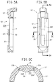
- Figures 5A, 5B and 5C are, respectively, side sectional, front elevational and top sectional views of the inboard segment 12' of an adapter 10' in accordance with the second embodiment of the present invention.
- the adapter 10' is especially configured to facilitate removal of bands of material formed during a equilibrium centrifugation separation.
- the adapter 10' may be segmented as shown in Figures 3 and 4 or integrally formed.
- the radially inward segment 12' or the portion of the adapter 10' that lies radially inboard when in use has an opening 20' therein.
- the opening 20' is adapted to expose a portion of a tube T carried within the adapter.
- the opening 20' must be sized to allow the sample to be exposed to an ultraviolet light source and to enable the band to be visually located.
- the position of the opening 20' should be such that the portion of the tube containing the band of material of interest and a region therabove (for venting purposes) is exposed and accessible.
- the size and position of the opening 20' should be such as to expose and make accessible the maximum possible portion of the length of the tube (including the neck portion n thereof).
- the size and position of the opening 20' should also be governed by the consideration of "sufficient strength to support itself" explained earlier. Since the sufficient strength consideration competes with the considerations of exposure and accessibilty discussed immediately above, in practice a suitable trade-off among operating speed, window size, and window position is required.
- the adapter 10' has guide tracks 22A, 22B formed in the material of the adapter surrounding the opening 20'.
- a plug 24 has grooves 26A, 26B. The grooves 26A, 26B receive the guide tracks 22A, 22B whereby the plug 24 is slidably disposed along and selectably positionable within the opening 20'.
- the plug 24 has an inside surface 28I and an exterior surface 28E. The inside surface 28I of the plug 24 is presented toward the tube within the adapter 10'.
- the surface 28I has a layer of a sealing material 30, such as an elastomeric material, thereon.
- the plug 24 is sized so that it may be carried on the adapter 10' during centrifugation and so that the sealing material 30 is biased into contact with the tube carried within the adapter.
- the tracks 22A, 22B are sized to provide support for the plug during centrifugation. No portion of the plug should extend outwardly beyond the outer diameter of the adapter 10 else a suitable opening must be provided in the rotor. Alternately, the plug 24 may be separate from the adapter 10' and inserted thereinto at the termination of a centrifugation run.
- the exterior surface 28E has serrations 34 thereon to facilitate movement. If desired, additional plug(s) may be provided in the opening 20'.
- the adapter 10' may be fabricated from a material (such as that earlier identified) that is transmissive to visible light.
- the material should be sufficiently translucent to permit visual location by an operator of a band of material of interest that has been exposed to ultraviolet light through the opening 20'. Most preferably, the material should be transparent. It is noted that the limitations imposed on the size of the opening 20' necessary to permit the band to be exposed to ultraviolet light may be disregarded if a material that is transmissive to both ultraviolet and visible light can be found to fabricate the adapter.
- the adapter 10' with the tube therein is removed from the rotor.
- the adapter 10' may be held by hand or held by a clamp as the band of material of interest removed.
- the adapter 10' may be inserted into a suitable stand to provide access to the opening 20' and to hold securely the adapter in place.
- an operator would not be required to steady the adapter 20' during withdrawal of a band of material. The potential risk of puncture is thus avoided.
- a plug 24 is slid along the opening 20' until the sealing material 30 on the inside surface 28I thereof is positioned over the puncture in the tube. Since the sealing material 30 is biased into sealing engagement with the tube, liquid leakage through the puncture is effectively stopped. The magnitude of the biasing force need only be sufficient to prevent leakage while the tube is at rest. Additional withdrawal(s) of material may then be made.
Landscapes
- Centrifugal Separators (AREA)
Description
- The present invention relates to a cartridge adapter for a centrifuge tube.
- PCT publication WO 91/06373 discloses a cartridge adapter for supporting a sealed centrifuge tube within a cavity of a centrifuge rotor. The cartridge adapter comprises a pair of matable adapter segments, each of which has an indentation therein. When the segments are joined along mating surfaces the indentation in each segment cooperate to define a recess having a size and shape that closely corresponds (within a certain range of manufacturing tolerances) to the size and shape of some portion or all of the sealed centrifuge tube. When the cartridge adapter is introduced into a rotor cavity one of the two segments, termed the inboard segment Ai, lies radially closer to the axis of rotation VCL. The inboard segment Ai has a keying feature thereon which identifies it as the segment that is introduced into the radially inboard side of the cavity C. The other segment, termed the radially outboard segment Ao, lies radially outwardly of the inboard segment and radially further from the axis of rotation VCL.
- Figures 1A and 1B are top sectional views, taken in a plane transverse to the longitudinal axis of a prior art sealed plastic centrifuge tube T illustrating the inboard and outboard segments Ai, Ao, respectively, of a cartridge adapter as they support the tube T within a cavity C of a rotor V, illustrated as a vertical angle rotor. At rest, as shown in Figure 1A, the inside surfaces of the respective inboard and outboard segments Ai and Ao of the adapter lie (within dimensional tolerances) close to or in physical contact with the exterior surface of the sealed tube about its entire circumference. It is noted that the inside surfaces of the adapter segments lie in this disposition with respect to the tube throughout the tube's entire axial length. That is, for each transverse section along the longitudinal axis of the tube, the relationship shown in Figure 1A is maintained.
- With reference to Figure 1B, as the rotor is spun about the axis of rotation VCL the tube T is exposed both to a radially outwardly directed force Fc and an internal hydrostatic pressure force Fh. The force Fc is caused by the mass of the tube itself under centrifugal load. The force Fh is caused by the mass of the liquid contents of the tube under centrifugal load. In a first portion P1 of the tube, viz., a portion of the tube T received in the radially inboard segment Ai, the vector sum of the forces Fc and Fh is such that the tube deflects radially outwardly to form a depression indicated by the character D in Figure 1B. The outer surface of this portion P1 of the tube is spaced from, or defines a clearance with, the adjacent region R of the inner surface of the inboard segment Ai. This spacing is indicated by the character S in Figure 1B, while the region R of the inboard segment Ai is indicated by the dot-dash arc. The radial magnitude of the spacing S is dependent upon both the volume, the compressibility of the liquid within the sealed tube, and, in some instances, the fit of the tube T into the adapter.
- Throughout the remaining portion of the circumference of the tube T the vector sum of the forces Fc and Fh is such that the exterior of the tube T is forced into intimate contacting relationship with the inner surface of the inboard and outboard segments Ai and Ao of the adapter lying adjacent thereto. The region of intimate contact is indicated by the relatively heavy line of contact.
- As may be appreciated the depression D formed as described has a length dimension measured along the longitudinal axis of the tube. The magnitude of this length dimension is also dependent upon both the volume and the compressibility of the liquid within the tube. If, for example, a tube were completely filled with an incompressible liquid, the force of the liquid would balance the centrifugal force and the depression would likely not form. Since, in practice, the tube is seldom totally filled and liquids are compressible to some extent, a depression D is likely to form along some portion of the length of the radially inward portion of the tube T. The depression may be envisioned as a dimple in the radially inward portion of the tube.
- Since the material of the tube in the depression D is spaced from the inner surface of the region R of the inboard segment Ai the hydrostatic force of the liquid within the tube T is not able to provide any support for this region of the inboard segment Ai. The hydrostatic force of the liquid within the tube T does, however, provide some support to that region of the inboard segment Ai into which the tube T has been forced into intimate contacting relationship. As a result, in use, the unsupported region R of the inboard segment of the adapter is deflected radially outwardly.
- The magnitude of the deflection is illustrated in Figure 2 by surface contours of constant deflection or stress. Although Figure 2 is a vertical perspective taken along a vertical central plane through one half of the inboard segment Ai it should be understood that the surface contours shown in Figure 2 are symmetric about the vertical central plane. The magnitude of the relative deflections of the region R of the inboard segment Ai of the adapter are indicated by the characters δ1 through δ4. Since relatively greater deflections produce relatively greater stresses in the adapter segment the surface contours indicating the relative magnitude of the attendant stresses are similar in form to the surface contours of the deflection. The stress contours are thus shown in Figure 2 and are indicated by the characters σ1 through σ4, respectively. The character δ1 and the character σ1 indicate the greatest magnitude of deflection or stress, as the case may be. Those areas of the inboard segment Ai experiencing higher deflections and higher stresses are more likely to fail.
- WO-A-92/19382 discloses an adapter for holding a centrifuge tube in a centrifuge rotor cavity comprising two segments which may be hinged along a hinge axis that extends perpendicular to the axis of the adapter. The inboard segment is subjected to deflections and stress as set out above.
- Another centrifuge tube adapter having two segments is disclosed in WO-A-86/05718. The two segments are hinged along the lateral edges of the segments. The hinge axis lies in parallel relationship to the axis of the cavity in which the adapter is received. No efforts are made to reduce deflection and stress of the inboard segment of the adapter.
- DE 35 12 848 discloses a centrifuge of the swinging bucket type having buckets to receive centrifuge tubes which will swing upon centrifugation from a vertical to a horizontal position. Each bucket has a window located on the outboard portion of the bucket to allow inspection of the content of a transparent centrifuge tube.
- It is an object of the invention to provide an adapter in which the areas of relatively higher deflections and higher stresses are eliminated or substantially reduced.
- This object is solved, according to the invention, with the features of
claim 1. - It is common practice in molecular biology applications to utilize a technique termed "equilibrium centrifugation" to isolate various materials in a sample in accordance with their respective density. Typically ethidium bromide, a mutagen, is intercalculated in the material of interest. After centrifugation, with the tube at rest and upright, the materials reorient to form transverse bands at longitudinally spaced locations along the axis of the tube. The ethidium bromide when exposed to ultraviolet light absorbs the ultraviolet light and emits a visible fluorescent light which facilitates location of the band having the material of interest.
- One prevalent method to withdraw a band having a material of interest is to hold the tube in a position so that ultraviolet light can shine therethrough to locate the band. The tube may be held by hand or clamped to a stand. A vent needle is inserted into the tube above that band (usually near to the top of the tube). The operator must steady the tube (whether or not it is clamped) while a syringe is then inserted into the tube. The syringe is inserted such that the tip thereof lies immediately beneath the band of material of interest enabling that band to be withdrawn. This process is repeated for each band having a material of interest.
- This technique is perceived to exhibit a variety of drawbacks. The operator is exposed to the risk of puncture while handling the tube during the withdrawal process. Further, as should be readily apparent, once the syringe is removed from the tube, liquid from the tube leaks through the punctured opening therein the tube. Typical expedients for preventing such leaks include taping the tube wall or closing the puncture with the clinician's finger until such time as the tube may be deposited into a pool of inactivating liquid. Since ethidium bromide is a known mutagen physical contact with it should be minimized.
- Accordingly, in view of the foregoing it is believed advantageous to provide an adapter according to claims 4-6 that supports the tube during centrifugation and also facilitates removal of material without the perceived disadvantages of the prior art.
- A first embodiment of the present invention is directed to an adapter for use in a fixed angle centrifuge rotor, the adapter having, while being spun, a portion that lies radially inboard and an portion that lies outboard with respect to an axis of rotation. The adapter has a recess sized to receive a centrifuge tube. The tube is exposed, during centrifugation, to a load that causes a first portion of the tube to deflect radially outwardly from a first region of the inboard portion of the adapter while a second, adjacent, portion of the tube is forced into intimate contact with a second region of the inboard portion of the adapter. In accordance with the present invention the improvement in the adapter comprises an opening formed in the radially inboard portion of the adapter. Preferably, the opening is substantially coextensive with the first region of the inboard portion of the adapter. By appropriately sizing the opening substantially no part of the inboard portion of the adapter is exposed during centrifugation to a load that exceeds the ability of the material of the adapter to support itself. Stated alternatively, the material of the inboard portion of the adapter surrounding the opening has sufficient strength to support itself while under centrifugation.
- This aspect of the invention may be used with any form of adapter, whether it is integral or segmented. In the event the adapter is formed from matable inboard and outboard segments Ai, Ao, respectively, the opening is provided in the inboard segment Ai.
- In accordance with a second embodiment of the invention the adapter includes a plug that is slidably disposed and selectably positionable within the opening in the inboard segment of the adapter. The plug has an inside and an outside surface thereon. The inside surface of the plug has a sealing material thereon. The sealing material is biased into contact with a tube carried within the adapter. In the preferred embodiment the opening is large enough to allow the sample to be exposed to an ultraviolet light source and to enable the band to be visually located. Alternatively or additionally, the adapter may be fabricated from a material transmissive to visible light, so that a band exposed to ultraviolet light through the opening may be visually located through the adapter.
- The invention will be more fully understood from the following detailed description, taken in connection with the accompanying drawings, in which:
- Figures 1A and 1B are a top sectional views, taken in a plane transverse to the longitudinal axis of a sealed centrifuge tube, illustrating the inboard and outboard segments of an adapter of the prior art when supporting the sealed tube within a cavity C of a rotor R while at rest and while spinning, respectively;
- Figure 2 is a vertical perspective taken along a vertical central plane through the inboard segment Ai illustrating the surface contours of deflections and stress therein due to the formation of a depressed region in the tube while the tube is being spun, with the surface contours being symmetric about the central plane;
- Figure 3 is an exploded perspective view of an adapter for a centrifuge tube in accordance with the first embodiment of the present invention, with the majority of the Figure being shown in perspective while a portion thereof is shown in vertical cross section;
- Figures 4A and 4B are, respectively, perspective views illustrating the interior and the exterior surfaces of the inboard segment of the adapter of Figure 3, respectively; and
- Figures 5A, 5B and 5C are, respectively, side sectional, front elevational (looking toward the inside surface) and top sectional views of an adapter in accordance with the second embodiment of the present invention, with the tube being suggested in Figure 5A.
-
- Throughout the following detailed description similar reference characters refer to similar elements in all Figures of the drawings.
- With reference to Figures 3, 4A and 4B, respectively shown are various perspective views of an adapter generally indicated by the
reference character 10 in accordance with the first embodiment the present invention. Theadapter 10 is used to adapt tubes T for centrifugation in a fixed angle centrifuge rotor V. The rotor V has cavities C therein. Each cavity may have a notch N therein. - In the illustrated embodiment the
adapter 10 has aninboard segment 12 and anoutboard segment 14. Theinboard segment 12 may have akeying feature 12K thereon which is received in the notch N. Bothsegments indentation adapter segments indentations segments adapter 10 are in the preferred case fabricated, as by injection molding, from a material such as thirty percent carbon fiber reinforced polyphthalamide such as that sold by RTP Company, Winona, Minnesota under product number RTP 4085. In those instances when the material of the adapter is light transmissive (as discussed herein), theadapter 10 may be injection molded from a polycarbonate plastic material. - As used in this application the term "fixed angle centrifuge rotor" means a rotor of the type having cavities formed in the body thereof so that, when a tube is received therein the axis At of each tube is inclined at a predetermined angular inclination with respect to the axis of rotation VCL and remains in that inclination throughout the centrifugation run. In this sense a "fixed angle centrifuge rotor" is to be distinguished from a so-called "swinging bucket centrifuge rotor" in which the inclination of the tube with respect to the axis of rotation is initially at approximately zero degrees and which, under centrifugation, swings to an orientation in which the axis of the tube is substantially perpendicular to the axis of rotation. The angular inclination of the axis At of the tube may be produced by inclining the axis Ac of the cavity C in the rotor with respect to the axis of rotation VCL, and/or by inclining the axis Ar of the
recess 16 in theadapter 10. Any angular value including zero degrees (a so-called "vertical rotor") may be used. - For the reasons discussed earlier, the tube is exposed, during centrifugation, to a load that causes a first portion of the tube to deflect radially outwardly from a first region of the
inboard segment 12 of the adapter (corresponding to the region R as discussed above), while a second, adjacent, portion of the tube is forced into intimate contact with a second region of the inboard segment of the adapter. In an adapter in accordance with the present invention theinboard segment 12 has anopening 20 therein. Theopening 20 is substantially coextensive with the first region first of theinboard segment 12. Theopening 20 is sized so that substantially no portion of theinboard segment 12 of the adapter is exposed under centrifugation to a load that exceeds the ability of the material of the adapter to support itself. Stated alternatively, theopening 20 is sized so that the material of theinboard segment 12 of the adapter surrounding theopening 20 has sufficient strength to support itself while under centrifugation. The term "sufficient strength to support itself" means that theadapter 10 is not likely to fail when used at a predetermined maximum operating speed over a predetermined useful lifetime of cyclic operation. It should be understood that the term "substantially coextensive" as used throughout this application is meant to encompass an instance in which either more than or less than the entire first region of the inboard segment of the tube is removed. The intent is that by making the opening substantially coextensive with the first region of theinboard segment 12, the areas of relatively higher deflections and higher stresses are either eliminated or substantially reduced. - Although the invention has been heretofore described in the context of an adapter formed of matable segments as described in PCT publication WO 91/06373, the invention may be used with equal utility with an adapter that is integrally formed and which, in use, has a portion thereof that is radially inboard with respect to the axis of rotation and a portion that lies radially outboard with respect to the axis of rotation. The opening is provided in the radially inboard portion of such an integrally formed adapter. The opening is sized as discussed, so that the material of the inboard portion of the adapter surrounding the opening has sufficient strength to support itself while under centrifugation and so that no portion of the adapter is exposed under centrifugation to a load that exceeds the ability of the material of the adapter to support itself.
- Figures 5A, 5B and 5C are, respectively, side sectional, front elevational and top sectional views of the inboard segment 12' of an adapter 10' in accordance with the second embodiment of the present invention. The adapter 10' is especially configured to facilitate removal of bands of material formed during a equilibrium centrifugation separation. The adapter 10' may be segmented as shown in Figures 3 and 4 or integrally formed.
- The radially inward segment 12' or the portion of the adapter 10' that lies radially inboard when in use has an opening 20' therein. The opening 20' is adapted to expose a portion of a tube T carried within the adapter. To permit withdrawal of a band of material of interest from the tube the opening 20' must be sized to allow the sample to be exposed to an ultraviolet light source and to enable the band to be visually located. Additionally, the position of the opening 20' should be such that the portion of the tube containing the band of material of interest and a region therabove (for venting purposes) is exposed and accessible. To permit withdrawal of any band of material of interest wherever it is located within the tube, the size and position of the opening 20' should be such as to expose and make accessible the maximum possible portion of the length of the tube (including the neck portion n thereof).
- The size and position of the opening 20' should also be governed by the consideration of "sufficient strength to support itself" explained earlier. Since the sufficient strength consideration competes with the considerations of exposure and accessibilty discussed immediately above, in practice a suitable trade-off among operating speed, window size, and window position is required.
- The adapter 10' has
guide tracks plug 24 hasgrooves grooves plug 24 is slidably disposed along and selectably positionable within the opening 20'. Theplug 24 has an inside surface 28I and an exterior surface 28E. The inside surface 28I of theplug 24 is presented toward the tube within the adapter 10'. The surface 28I has a layer of a sealingmaterial 30, such as an elastomeric material, thereon. - The
plug 24 is sized so that it may be carried on the adapter 10' during centrifugation and so that the sealingmaterial 30 is biased into contact with the tube carried within the adapter. Thetracks adapter 10 else a suitable opening must be provided in the rotor. Alternately, theplug 24 may be separate from the adapter 10' and inserted thereinto at the termination of a centrifugation run. - The exterior surface 28E has serrations 34 thereon to facilitate movement. If desired, additional plug(s) may be provided in the opening 20'.
- The adapter 10' may be fabricated from a material (such as that earlier identified) that is transmissive to visible light. The material should be sufficiently translucent to permit visual location by an operator of a band of material of interest that has been exposed to ultraviolet light through the opening 20'. Most preferably, the material should be transparent. It is noted that the limitations imposed on the size of the opening 20' necessary to permit the band to be exposed to ultraviolet light may be disregarded if a material that is transmissive to both ultraviolet and visible light can be found to fabricate the adapter.
- In use, after centrifugation, the adapter 10' with the tube therein is removed from the rotor. The adapter 10' may be held by hand or held by a clamp as the band of material of interest removed. Alternatively, and more preferably, the adapter 10' may be inserted into a suitable stand to provide access to the opening 20' and to hold securely the adapter in place. Thus, an operator would not be required to steady the adapter 20' during withdrawal of a band of material. The potential risk of puncture is thus avoided.
- After removal of the syringe from the tube, a
plug 24 is slid along the opening 20' until the sealingmaterial 30 on the inside surface 28I thereof is positioned over the puncture in the tube. Since the sealingmaterial 30 is biased into sealing engagement with the tube, liquid leakage through the puncture is effectively stopped. The magnitude of the biasing force need only be sufficient to prevent leakage while the tube is at rest. Additional withdrawal(s) of material may then be made.
Claims (6)
- An assembly of a fixed angle centrifuge rotor (V), an adapter (10;10') and a centrifuge tube (T) for use within a cavity (C) of the rotor (V), the adapter (10;10') having, while being spun, a portion that lies radially inboard and a portion that lies radially outboard with respect to an axis of rotation (VCL), the adapter (10;10') having a recess (16) sized to receive the centrifuge tube (T),
characterized by
the inboard portion of the adapter (10;10') having an opening (20;20') therein, located in an area (P1) in which the centrifuge tube (T) imparts stress while being spun, thus reducing the deflection of the adapter (10;10') in that area (P1). - The assembly of claim 1 wherein the adapter (10;10') has an inboard (12;12') and an outboard (14;14') segment, the inboard segment (12;12') and the outboard segment (14;14') each have an indentation (12I,14I) therein which cooperate to define the recess (16) sized to receive the centrifuge tube (T).
- The assembly of claim 2 wherein the material of the inboard (12;12') and outboard (14;14') segments is a light transmissive material.
- The assembly of claim 2 or 3 comprising a plug (24) slidably disposed and selectably positionable within the opening (20') in the inboard segment (12').
- The assembly of claim 4 wherein the plug (24) has an inside and an outside surface thereon, the inside surface of the plug (24) having a sealing material (30) thereon.
- The assembly of claim 5 wherein the dimension of the plug (24) being such that the sealing material (30) is biased into contact with a tube (T) received within the adapter (10').
Applications Claiming Priority (2)
| Application Number | Priority Date | Filing Date | Title |
|---|---|---|---|
| US68498 | 1993-05-27 | ||
| US08/068,498 US5935052A (en) | 1993-05-27 | 1993-05-27 | Adapter for centrifuge tube |
Publications (3)
| Publication Number | Publication Date |
|---|---|
| EP0626206A2 EP0626206A2 (en) | 1994-11-30 |
| EP0626206A3 EP0626206A3 (en) | 1995-05-17 |
| EP0626206B1 true EP0626206B1 (en) | 1999-07-21 |
Family
ID=22082971
Family Applications (1)
| Application Number | Title | Priority Date | Filing Date |
|---|---|---|---|
| EP94107533A Expired - Lifetime EP0626206B1 (en) | 1993-05-27 | 1994-05-16 | Adapter for centrifuge tube |
Country Status (5)
| Country | Link |
|---|---|
| US (1) | US5935052A (en) |
| EP (1) | EP0626206B1 (en) |
| JP (1) | JP3630718B2 (en) |
| CN (1) | CN1098967A (en) |
| DE (1) | DE69419565T2 (en) |
Families Citing this family (9)
| Publication number | Priority date | Publication date | Assignee | Title |
|---|---|---|---|---|
| US6770244B2 (en) * | 2001-05-03 | 2004-08-03 | Hitachi Chemical Diagnostic, Inc. | Dianostic sample tube including anti-rotation apparatus |
| JP3863465B2 (en) * | 2002-07-17 | 2006-12-27 | 株式会社久保田製作所 | centrifuge |
| US7118522B2 (en) * | 2003-04-15 | 2006-10-10 | Beckman Coulter, Inc. | Centrifuge adapter |
| DE102004062233B4 (en) * | 2004-12-23 | 2020-09-03 | Thermo Electron Led Gmbh | Centrifuge adapter and closure |
| EP2475462A2 (en) * | 2009-09-10 | 2012-07-18 | Robert Aaron Levine | Systems and methods for reducing expansion of fluid containing tubes during centrifugation |
| JP2011125813A (en) * | 2009-12-18 | 2011-06-30 | National Cancer Center | Centrifugal separation container, adapter for retaining position of centrifugal separation container and centrifugal separation implement |
| JP5886404B2 (en) * | 2014-11-25 | 2016-03-16 | 国立研究開発法人国立がん研究センター | Centrifuge tool |
| JP6431438B2 (en) * | 2015-04-28 | 2018-11-28 | 株式会社フコク | Adapter for maintaining the position of centrifuge containers |
| USD1000634S1 (en) * | 2021-08-19 | 2023-10-03 | Hitachi High-Tech Corporation | Adaptor for sample rack |
Family Cites Families (29)
| Publication number | Priority date | Publication date | Assignee | Title |
|---|---|---|---|---|
| US486390A (en) * | 1892-11-15 | Centrifugal cream-tester | ||
| US780315A (en) * | 1904-08-05 | 1905-01-17 | Henry Emerson Wetherill | Haematokrit. |
| US1648369A (en) * | 1923-09-10 | 1927-11-08 | Svedberg Theodor | Analytical centrifuge |
| US2617585A (en) * | 1950-03-31 | 1952-11-11 | Beyerle Konrad | Rotating system for observation centrifuges for the determination of molecular weight |
| US2878944A (en) * | 1957-02-11 | 1959-03-24 | Barnes George Elliot | Automatic water remover for carburetors |
| US3027799A (en) * | 1959-01-26 | 1962-04-03 | Brunswick Corp | Sample space adapters for spectrophotometers and the like |
| GB1095429A (en) * | 1965-05-17 | |||
| US3361343A (en) * | 1965-11-01 | 1968-01-02 | Irwin S. Lerner | Hematological centrifuge |
| DE1966274C3 (en) * | 1969-03-11 | 1979-07-05 | Fa. Andreas Hettich, 7200 Tuttlingen | Centrifuge with a centrifugal head for holding transparent sample vessels |
| DE1966805C3 (en) * | 1969-03-11 | 1982-05-13 | Fa. Andreas Hettich, 7200 Tuttlingen | Tube carriers for centrifuges |
| US3674197A (en) * | 1970-09-08 | 1972-07-04 | Sorvall Inc Ivan | Washing means for flexible bags in split enclosures |
| US3891140A (en) * | 1974-02-27 | 1975-06-24 | Becton Dickinson Co | Centrifuge |
| US3951334A (en) * | 1975-07-07 | 1976-04-20 | E. I. Du Pont De Nemours And Company | Method and apparatus for automatically positioning centrifuge tubes |
| US3998383A (en) * | 1975-07-16 | 1976-12-21 | E. I. Du Pont De Nemours And Company | Gradient separation apparatus |
| US4141489A (en) * | 1977-11-02 | 1979-02-27 | Beckman Instruments, Inc. | Swinging carrier centrifuge rotor |
| US4290550A (en) * | 1980-02-19 | 1981-09-22 | Beckman Instruments, Inc. | Modular supporting cap and spacer for centrifuge tubes |
| US4304356A (en) * | 1980-02-19 | 1981-12-08 | Beckman Instruments, Inc. | Supporting cap for sealed centrifuge tube |
| US4306676A (en) * | 1980-04-17 | 1981-12-22 | Beckman Instruments, Inc. | Tube holder for centrifuge rotor |
| US4375272A (en) * | 1981-07-01 | 1983-03-01 | Beckman Instruments, Inc. | Fixed angle tube carrier |
| US4511349A (en) * | 1982-07-06 | 1985-04-16 | Beckman Instruments, Inc. | Ultracentrifuge tube with multiple chambers |
| DE3343846C2 (en) * | 1983-12-03 | 1987-02-12 | Heraeus Separationstechnik GmbH, 3360 Osterode | Centrifuge rotor |
| DE3512848A1 (en) * | 1984-04-10 | 1985-10-17 | Walter Sarstedt Kunststoff-Spritzgußwerk, 5223 Nümbrecht | Centrifuge |
| US4552278A (en) * | 1984-10-30 | 1985-11-12 | E. I. Du Pont De Nemours And Company | Crimpable capping assembly for a centrifuge tube |
| US4692137A (en) * | 1985-04-03 | 1987-09-08 | Beckman Instruments, Inc. | Split tube centrifuge rotor adapter |
| US4844818A (en) * | 1987-10-23 | 1989-07-04 | Becton Dickinson & Company | Method for separating the cellular components of blood samples |
| DE8902975U1 (en) * | 1989-03-10 | 1990-04-19 | Fa. Andreas Hettich, 7200 Tuttlingen | Insert cups for centrifuges |
| IE903997A1 (en) * | 1989-11-07 | 1991-05-08 | Du Pont | Hinged centrifuge tube adapter |
| CA2102320A1 (en) * | 1991-05-06 | 1992-11-07 | William Andrew Romanauskas | Centrifuge tube adapter |
| CA2067695C (en) * | 1991-06-06 | 1997-07-08 | James A. Burns | Blood microcollection tube assembly |
-
1993
- 1993-05-27 US US08/068,498 patent/US5935052A/en not_active Expired - Lifetime
-
1994
- 1994-05-16 EP EP94107533A patent/EP0626206B1/en not_active Expired - Lifetime
- 1994-05-16 DE DE69419565T patent/DE69419565T2/en not_active Expired - Fee Related
- 1994-05-27 JP JP11568694A patent/JP3630718B2/en not_active Expired - Lifetime
- 1994-05-27 CN CN94106163.9A patent/CN1098967A/en active Pending
Also Published As
| Publication number | Publication date |
|---|---|
| JP3630718B2 (en) | 2005-03-23 |
| CN1098967A (en) | 1995-02-22 |
| EP0626206A2 (en) | 1994-11-30 |
| JPH0751595A (en) | 1995-02-28 |
| DE69419565T2 (en) | 2000-07-06 |
| US5935052A (en) | 1999-08-10 |
| DE69419565D1 (en) | 1999-08-26 |
| EP0626206A3 (en) | 1995-05-17 |
Similar Documents
| Publication | Publication Date | Title |
|---|---|---|
| US5935052A (en) | Adapter for centrifuge tube | |
| US3898046A (en) | Stopper for sealing containers | |
| EP0640215B1 (en) | Phase-separation method | |
| US8215508B2 (en) | Centrifuge bottle closure and assembly thereof | |
| JP4568434B2 (en) | Sealing lid for multiple penetrations | |
| US5707589A (en) | Funnel-shaped sample-vial septum with membrane covered diffusion-barrier section | |
| JP3342933B2 (en) | Complete removal type container and method | |
| US4290550A (en) | Modular supporting cap and spacer for centrifuge tubes | |
| US20010056264A1 (en) | Syringe | |
| US8105556B2 (en) | Centrifuge adapter and closure | |
| JP2003519003A (en) | Container assembly with support bridge | |
| US4451250A (en) | Inside adapter for a sample container | |
| JPS63115560A (en) | Improved capsule | |
| US5180643A (en) | Hydrometer collar improvement | |
| EP0449425B1 (en) | Self-seal centrifuge tube | |
| CA1123385A (en) | Tightly sealing safety cap | |
| GB2222538A (en) | Centrifuge tube adapter | |
| EP0500768B1 (en) | Hinged centrifuge tube adapter | |
| EP0626207B1 (en) | Adapter for holding a pair of centrifuge tubes | |
| EP0643629B1 (en) | Centrifuge tubes with snap plugs | |
| JP2002517160A (en) | Centrifuge bottle with slanted neck | |
| GB2050320A (en) | Closure for container | |
| EP0584277A1 (en) | Centrifuge tube adapter | |
| JPS584593Y2 (en) | centrifuge tube | |
| US5461889A (en) | Plastic spacer ring having an annular groove for sealing plastic dye tubes |
Legal Events
| Date | Code | Title | Description |
|---|---|---|---|
| PUAI | Public reference made under article 153(3) epc to a published international application that has entered the european phase |
Free format text: ORIGINAL CODE: 0009012 |
|
| AK | Designated contracting states |
Kind code of ref document: A2 Designated state(s): DE FR GB IE IT |
|
| PUAL | Search report despatched |
Free format text: ORIGINAL CODE: 0009013 |
|
| AK | Designated contracting states |
Kind code of ref document: A3 Designated state(s): DE FR GB IE IT |
|
| 17P | Request for examination filed |
Effective date: 19950623 |
|
| 17Q | First examination report despatched |
Effective date: 19970303 |
|
| RAP1 | Party data changed (applicant data changed or rights of an application transferred) |
Owner name: SORVALL PRODUCTS, L.P. |
|
| GRAG | Despatch of communication of intention to grant |
Free format text: ORIGINAL CODE: EPIDOS AGRA |
|
| GRAG | Despatch of communication of intention to grant |
Free format text: ORIGINAL CODE: EPIDOS AGRA |
|
| GRAH | Despatch of communication of intention to grant a patent |
Free format text: ORIGINAL CODE: EPIDOS IGRA |
|
| GRAH | Despatch of communication of intention to grant a patent |
Free format text: ORIGINAL CODE: EPIDOS IGRA |
|
| GRAA | (expected) grant |
Free format text: ORIGINAL CODE: 0009210 |
|
| AK | Designated contracting states |
Kind code of ref document: B1 Designated state(s): DE FR GB IE IT |
|
| PG25 | Lapsed in a contracting state [announced via postgrant information from national office to epo] |
Ref country code: IT Free format text: LAPSE BECAUSE OF FAILURE TO SUBMIT A TRANSLATION OF THE DESCRIPTION OR TO PAY THE FEE WITHIN THE PRESCRIBED TIME-LIMIT;WARNING: LAPSES OF ITALIAN PATENTS WITH EFFECTIVE DATE BEFORE 2007 MAY HAVE OCCURRED AT ANY TIME BEFORE 2007. THE CORRECT EFFECTIVE DATE MAY BE DIFFERENT FROM THE ONE RECORDED. Effective date: 19990721 |
|
| REF | Corresponds to: |
Ref document number: 69419565 Country of ref document: DE Date of ref document: 19990826 |
|
| REG | Reference to a national code |
Ref country code: IE Ref legal event code: FG4D |
|
| ET | Fr: translation filed | ||
| PG25 | Lapsed in a contracting state [announced via postgrant information from national office to epo] |
Ref country code: IE Free format text: LAPSE BECAUSE OF NON-PAYMENT OF DUE FEES Effective date: 20000516 |
|
| PLBE | No opposition filed within time limit |
Free format text: ORIGINAL CODE: 0009261 |
|
| STAA | Information on the status of an ep patent application or granted ep patent |
Free format text: STATUS: NO OPPOSITION FILED WITHIN TIME LIMIT |
|
| 26N | No opposition filed | ||
| REG | Reference to a national code |
Ref country code: IE Ref legal event code: MM4A |
|
| PGFP | Annual fee paid to national office [announced via postgrant information from national office to epo] |
Ref country code: GB Payment date: 20010516 Year of fee payment: 8 |
|
| REG | Reference to a national code |
Ref country code: GB Ref legal event code: IF02 |
|
| PGFP | Annual fee paid to national office [announced via postgrant information from national office to epo] |
Ref country code: FR Payment date: 20020501 Year of fee payment: 9 |
|
| PG25 | Lapsed in a contracting state [announced via postgrant information from national office to epo] |
Ref country code: GB Free format text: LAPSE BECAUSE OF NON-PAYMENT OF DUE FEES Effective date: 20020516 |
|
| PGFP | Annual fee paid to national office [announced via postgrant information from national office to epo] |
Ref country code: DE Payment date: 20020520 Year of fee payment: 9 |
|
| GBPC | Gb: european patent ceased through non-payment of renewal fee |
Effective date: 20020516 |
|
| PG25 | Lapsed in a contracting state [announced via postgrant information from national office to epo] |
Ref country code: DE Free format text: LAPSE BECAUSE OF NON-PAYMENT OF DUE FEES Effective date: 20031202 |
|
| PG25 | Lapsed in a contracting state [announced via postgrant information from national office to epo] |
Ref country code: FR Free format text: LAPSE BECAUSE OF NON-PAYMENT OF DUE FEES Effective date: 20040130 |
|
| REG | Reference to a national code |
Ref country code: FR Ref legal event code: ST |