EP0626078B1 - Plasma treatment of polymer powders - Google Patents
Plasma treatment of polymer powders Download PDFInfo
- Publication number
- EP0626078B1 EP0626078B1 EP94901718A EP94901718A EP0626078B1 EP 0626078 B1 EP0626078 B1 EP 0626078B1 EP 94901718 A EP94901718 A EP 94901718A EP 94901718 A EP94901718 A EP 94901718A EP 0626078 B1 EP0626078 B1 EP 0626078B1
- Authority
- EP
- European Patent Office
- Prior art keywords
- nitrogen
- polymer
- oxygen
- powder
- plasma
- Prior art date
- Legal status (The legal status is an assumption and is not a legal conclusion. Google has not performed a legal analysis and makes no representation as to the accuracy of the status listed.)
- Expired - Lifetime
Links
Images




Classifications
-
- B—PERFORMING OPERATIONS; TRANSPORTING
- B29—WORKING OF PLASTICS; WORKING OF SUBSTANCES IN A PLASTIC STATE IN GENERAL
- B29C—SHAPING OR JOINING OF PLASTICS; SHAPING OF MATERIAL IN A PLASTIC STATE, NOT OTHERWISE PROVIDED FOR; AFTER-TREATMENT OF THE SHAPED PRODUCTS, e.g. REPAIRING
- B29C59/00—Surface shaping of articles, e.g. embossing; Apparatus therefor
- B29C59/14—Surface shaping of articles, e.g. embossing; Apparatus therefor by plasma treatment
-
- C—CHEMISTRY; METALLURGY
- C08—ORGANIC MACROMOLECULAR COMPOUNDS; THEIR PREPARATION OR CHEMICAL WORKING-UP; COMPOSITIONS BASED THEREON
- C08J—WORKING-UP; GENERAL PROCESSES OF COMPOUNDING; AFTER-TREATMENT NOT COVERED BY SUBCLASSES C08B, C08C, C08F, C08G or C08H
- C08J3/00—Processes of treating or compounding macromolecular substances
- C08J3/28—Treatment by wave energy or particle radiation
-
- G—PHYSICS
- G03—PHOTOGRAPHY; CINEMATOGRAPHY; ANALOGOUS TECHNIQUES USING WAVES OTHER THAN OPTICAL WAVES; ELECTROGRAPHY; HOLOGRAPHY
- G03G—ELECTROGRAPHY; ELECTROPHOTOGRAPHY; MAGNETOGRAPHY
- G03G9/00—Developers
- G03G9/08—Developers with toner particles
-
- B—PERFORMING OPERATIONS; TRANSPORTING
- B29—WORKING OF PLASTICS; WORKING OF SUBSTANCES IN A PLASTIC STATE IN GENERAL
- B29K—INDEXING SCHEME ASSOCIATED WITH SUBCLASSES B29B, B29C OR B29D, RELATING TO MOULDING MATERIALS OR TO MATERIALS FOR MOULDS, REINFORCEMENTS, FILLERS OR PREFORMED PARTS, e.g. INSERTS
- B29K2025/00—Use of polymers of vinyl-aromatic compounds or derivatives thereof as moulding material
-
- B—PERFORMING OPERATIONS; TRANSPORTING
- B29—WORKING OF PLASTICS; WORKING OF SUBSTANCES IN A PLASTIC STATE IN GENERAL
- B29K—INDEXING SCHEME ASSOCIATED WITH SUBCLASSES B29B, B29C OR B29D, RELATING TO MOULDING MATERIALS OR TO MATERIALS FOR MOULDS, REINFORCEMENTS, FILLERS OR PREFORMED PARTS, e.g. INSERTS
- B29K2033/00—Use of polymers of unsaturated acids or derivatives thereof as moulding material
- B29K2033/04—Polymers of esters
- B29K2033/12—Polymers of methacrylic acid esters, e.g. PMMA, i.e. polymethylmethacrylate
-
- B—PERFORMING OPERATIONS; TRANSPORTING
- B29—WORKING OF PLASTICS; WORKING OF SUBSTANCES IN A PLASTIC STATE IN GENERAL
- B29K—INDEXING SCHEME ASSOCIATED WITH SUBCLASSES B29B, B29C OR B29D, RELATING TO MOULDING MATERIALS OR TO MATERIALS FOR MOULDS, REINFORCEMENTS, FILLERS OR PREFORMED PARTS, e.g. INSERTS
- B29K2105/00—Condition, form or state of moulded material or of the material to be shaped
- B29K2105/25—Solid
- B29K2105/251—Particles, powder or granules
Definitions
- This invention relates to a method of improving the triboelectric properties of polymers particles by triboelectrification, especially the fine polymer particles used in toners in electrophotographic systems.
- the X-ray spot size was reduced to 150 ⁇ m.
- the charging of the polymer surface during X-ray exposure was controlled using the flood gun/screen technique [see C. B. Bryson, Surface Sci. 189/190 , 50 (1987)]. Binding energies have been corrected for the shifts observed due to sample charging and spectra are referenced to the C 1s hydrocarbon component which was assigned the value of 284.8 eV [see ASTM Standard, E1015, Vol. 03.06 (1984)].
- Indium as a metal foil was suspended in the gas flow just below the microwave cavity.
- a gas flow of 1000 sccm was used to transfer indium vapor to the surface of polystyrene particles in the normal place in the reactor shown in Fig. 1.
- XPS showed that a small concentration of indium was present on the surface as In +3 .
- the presence on the surface of low concentrations of indium caused a major increase in the electrical charge retained, as shown in Fig. 12.
Landscapes
- Physics & Mathematics (AREA)
- Chemical & Material Sciences (AREA)
- Engineering & Computer Science (AREA)
- Plasma & Fusion (AREA)
- General Physics & Mathematics (AREA)
- Health & Medical Sciences (AREA)
- Chemical Kinetics & Catalysis (AREA)
- Medicinal Chemistry (AREA)
- Polymers & Plastics (AREA)
- Organic Chemistry (AREA)
- Treatments Of Macromolecular Shaped Articles (AREA)
- Processes Of Treating Macromolecular Substances (AREA)
Description
- This invention relates to a method of improving the triboelectric properties of polymers particles by triboelectrification, especially the fine polymer particles used in toners in electrophotographic systems.
- The charging of materials by triboelectrification has been applied to a number of industrial products for some time. Since the invention of the electrophotographic technique used for copiers and non-impact printers by Carlson in 1938 [see United States patent no. 2,297,691 (Carlson, 1942)], the field has developed into a large commercial market. Recently, electrophotography has required higher resolution images than was necessary previously, for application in colour image systems [see E. Czech, W. Ostertag, SPIE 1253, Hard Copy and Printing Products, 64, (1990)]. For this purpose it is very important to control accurately the electrical charge of the fine polymer powders used as toners in electrophotographic systems [see S. Kume, The Institute of Electrostatics of Japan 10(5), 306 (1986)].
- Toners are fine polymer particles typically about 10 µm in diameter mixed with various additives and usually include a coloured dye. In a two-component development system, the toner particles are charged by making contact with larger metal beads known as carriers [see L.B. Schein, "Electrophotography and Development Physics", ISBN 3-see 540-18902-5, Springer Verlag (1988)]. The toner is transferred to the photoreceptor due to an attractive electric field to form a real image (development). For a high quality image, it is important to control the charge-to-mass ratio (Q/M) of the toner within predetermined limits. The Q/M varies with changes in environmental conditions and surface properties of the toner [see N. Matsui, K. Oka and Y. Inaba, J. Electrophotographics 30(3), 282 (1991)]. Much work has been done to investigate the triboelectrification of fine polymer powders [see J. Henniker, Nature 196, 474 (1962); C.B. Duke and T.J. Fabish, J. Appl. Phys. 49, 315 (1978); and L.B. Schein and M. Latta, J. Appl. Phys. 69 (10), 6817 (1991)], but the mechanisms are still not fully understood. Some investigations suggest that the nature of the chemical species on the surface is the most important aspect for controlling the triboelectric charge of the particle [see I. Shinohara, F. Yamamoto, H. Anzai, and S. Endo, J. Electrost. 2, 99 (1976), and H. W. Gibson, Polymer 25, 3 (1984)].
- According to a first aspect of the invention there is provided a method of improving the triboelectric properties of a polymer powder of polymer particles, characterised by positioning the polymer powder in the afterglow region of a gas plasma, the gas plasma being in a low-pressure stream of a gas containing nitrogen or oxygen, whereby the nitrogen or oxygen is incorporated into the surfaces of the polymer powder particles to form chemical bonds with polymer of the polymer particles, and characterised in that the said nitrogen or oxygen acts as a donor and the said polymer is polystyrene or polymethyl methacrylate.
- JP-A-4-318559 relates to a method of treating toner resin particles for use in electrophotography in which the particles are subjected to a low-temperature plasma reaction with oxygen gas so as to oxidise the surface of the particles. Styrene/n-butyl methacrylate copolymer is examplified as resin for the tuner.
- According to a second aspect of the invention there is provided a polymer powder of polymer particles obtainable by a method according to the first aspect of the present invention.
- According to a third aspect of the invention there is provided an electrophotographic toner comprising a polymer powder according to the Second aspect of the invention.
- For a better understanding of the invention, and to show how the same may be carried into effect, reference will now be made, by way of example, to the accompanying drawings, in which:-
- Fig. 1 is a schematic of the plasma reactor for powder treatment;
- Fig. 2 is a graph of the relationship between plasma treatment time and nitrogen, oxygen concentrations on PS powder;
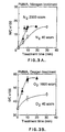
- Fig. 3 is a graph of the relationship between plasma treatment time and nitrogen, oxygen concentrations on PMMA powder;
- Fig. 4 is a graph of the relationship between mass of a) PS and b) PMMA powders and the concentration of nitrogen and oxygen observed;
- Fig. 5 is a graph of the C 1s spectra of a) nitrogen plasma treated PS and b) oxygen plasma treated PS powder;
- Fig. 6 is a graph of the C 1s spectra of a) nitrogen plasma treated PMMA and b) oxygen plasma treated PMMA powder;
- Fig. 7 is a graph of the relationship between Q/A versus N/C and O/C for PS powder electrified with a) negative carrier and b) positive carrier;
- Fig. 8 is a graph of the relationship between Q/A versus N/C and O/C for PMMA powder electrified with a) negative and b) positive carrier;
- Fig. 9 is a graph of the change in Q/A on nitrogen plasma treated PS powder as a function of time;
- Fig. 10 is a graph of the change in N/C on nitrogen plasma treated PS powder as a function of time;
- Figs. 11(a) and (b) are comparisons of the photoelectron yields of nitrogen-treated and untreated polystyrene;
- Fig. 12 is a graph of changes in Q/A for PS bombarded with In during In/Ar plasma treatment;
- Fig. 13 is a set of energy band diagrams for untreated a) PS and b) PMMA; and
- Fig. 14 is a set of energy band diagrams of a) nitrogen plasma and b) oxygen plasma treated PS.
-
- Polystyrene (PS) and polymethyl methacrylate (PMMA) powders in the form of small spherical beads were obtained from Sekisuikaseihin Co., (Tokyo, Japan). The XPS analysis was performed using an SSS-100 X-ray photoelectron spectrometer which utilizes monochromatized Al Kα X-rays for excitation of the sample. For analysis, the polymer sample was fixed on indium foil (5x5 mm2, 0.5 mm thickness) in a sample holder. For the elemental broad scan analysis, the X-ray spot size was set to 600 µm. The elemental broad scan was measured at the three different spots to ensure even and overall treatment of the powder. For high resolution analysis of the C 1s peak, the X-ray spot size was reduced to 150 µm. The charging of the polymer surface during X-ray exposure was controlled using the flood gun/screen technique [see C. B. Bryson, Surface Sci. 189/190, 50 (1987)]. Binding energies have been corrected for the shifts observed due to sample charging and spectra are referenced to the C 1s hydrocarbon component which was assigned the value of 284.8 eV [see ASTM Standard, E1015, Vol. 03.06 (1984)].
- Atomic percentages of oxygen and nitrogen were calculated using Scofield cross-sections correlated for differences in inelastic mean free path due to electron kinetic energy. The inelastic mean free path for C 1s electrons in PS was taken to be 2.9 nm [see R. F. Roberts, D. L. Allara, C. A. Pryde, D. N. E. Buchanan, and N. D. Hobbins, Surface and Interface analysis 2(1), 5 (1980)]. The atomic percentages of nitrogen and oxygen were converted into relative quantities as N/C (nitrogen/carbon atom ratio) or O/C (oxygen/carbon atom ratio).
- XPS showed the original PS powder (mass mean diameters of 8, 15, and 20 µm) to contain some oxygen O/C= 0.03 ±0.01 on the surface. This oxygen is thought to be the result of oxidation during processing. PMMA powder (mass mean diameters of 8, 12, and 20 µm) showed oxygen O/C= 0.35 ±0.01 on the surface. Since the properties of the powder surfaces change with atmospheric conditions [see Y. Nurata, Hyomen 23 (9), 528 (1985); K. P. Homewood, J. Electrostat. 10, 299 (1981)], it is important to control these conditions.
- Surface treatment of the powders was carried out in a vortex reactor located downstream from a microwave plasma discharge. The vortex reactor used during this work (Fig. 1) consisted of a 100
ml pyrex flask 1 with upper andside necks powder samples 4 were placed in the bottom in the flask along with a pyrex coveredmagnetic stirrer 5. The amount of powder sample used for each experiment was 0.3 - 1.2 g. The reactor was connected to the plasma by a 1.5 cm diameter quartz tube 6 fitted into theupper neck 2 of the flask. The upper part of this tube was surrounded by anEvenson microwave cavity 7 connected to a 120 W, 2.45GHz microwave generator 8. Theside neck 3 of the flask was connected to a high volume onestage rotary pump 9 with a pumping speed of ≈1.1x10⁶ sccm (standard cubic centimeters per minute). Afine cloth filter 10 was placed between the reactor and pump to prevent loss of powder to the pump. - Pure nitrogen gas (99.99%) and pure oxygen gas (99.99%) were used as plasma source gases, introduced via a
gas inlet 11. After the reactor was pumped to an initial base pressure of 7 Pa (5x10⁻² torr), the gas flow was typically set at a low flow rate (40 sccm) or at a high flow rate (O2; 1600 sccm, N2; 2000 sccm) for the experiments. The gas flow rates were controlled by a mass flow controller (not shown). The pressures in the reactor were 130 Pa (1.0 torr) (at 40 sccm), 470 Pa (3.5 torr) (at 1600 sccm), and 670 Pa (5.0 torr) (at 2000 sccm). The net microwave power for the experiments was set at 40 W. Treatment times were controlled and varied between 5 and 30 minutes. - In the above described configuration the sample is located ≈16 cm downstream from the plasma, and is therefore exposed only to the longer lived species in the
plasma afterglow region 12. Downstream plasma treatment of polymer surfaces has previously been studied [see R. Foerch et al J. Polymer Sci.: Appl. Polymer Symposium 46, 415 (1990)] and it has been shown that the efficiency of the treatment is dependent on the gas flow rate, the microwave power applied and the distance of the sample from the plasma [see R.Foerch et al J.Appl.Polymer Sci. 40, 1903(1990) and R.Foerch et al J.Polymer Sci., Part A, Polymer Chemistry 28,193 ]990)]. - In downstream plasma treatment, the reactive species of a gas plasma are reacted with a sample positioned a distance beyond the main plasma region, i.e. downstream from the main plasma region in terms of the direction of gas flow. The actual distance could vary from installation to installation. This is known as downstream or remote plasma modification, the main application of which to date has been in the electronics and semiconductor industry for the purpose of deposition of dielectric coatings on semi conductor devices or the cleaning of polymers (see Bachman U.S. patent no. 4,946,549).
- The downstream or remote plasma treatment in the present invention provides a much less destructive method for polymer treatment in comparison to direct plasma modification and other more commonly used methods such as corona discharge, ozone and flame treatment. In addition, the remote plasma treatment enables greater control over the reactive species interacting with the polymer, such that only the longer lived species, i.e. N atoms, reach the sample, rather than a whole range of electrons, ions and other excited species.
- The cage blowoff method is a simple and reproducible method for measuring the charge-to-mass ratio (Q/M) of polymer powders in contact with carrier particles [see L. B. Schein and J. Cranch, J. Appl. Phys 46, 5140 (1975)]. The carrier particles were made of polymer-coated ferrimagnetic particles, with a diameter of 120 µm. The plasma treated samples were mixed with the carriers in a 30 ml glass bottle. The ratio of the quantity of sample to carrier was changed with the diameter of the sample powders to ensure the same initial ratio of sample surface area to carrier surface area (0.5: 1) [see N. Hoshi and M. Anzai, J. Electrophotographics 25(4), 269 (1986)]. Thus, for a typical powder diameter of 8 µm, the mixing ratio of sample to carriers was 2.0 wt%, while for 20 µm the ratio was 4.5 wt%. A mixing time of 30 minutes at 120 rpm was utilized to electrify the samples sufficiently.
- After the mixing, the sample/carrier mixture was transferred to a double-walled aluminum Faraday cage (the "blowoff cage") with 44 µm metal mesh covering both ends of the inner container. The smaller powder particles were blown through the screen using a strong jet of air. The charge remaining on the carrier beads was measured using a Keithley Model 602 electrometer. This charge measured is equal and opposite to the charge on the powder. The change in mass before and after the blowoff was measured using a balance with an accuracy of ±0.1 mg. This data allowed Q/M to be calculated. Q/M measurements were repeated three times on different samples from the same batch of materials within 30 min. Two types of carriers were used to electrify the samples either with a negative charge or a positive charge. The difference between the two types of carriers lies in the surface polymer compositions of each of the surfaces.
- The charge density Q/A was calculated using the following equation to compare the samples of different diameters.
M d r - Q/A is the charge density [µC/m2],
- Q/M is the-charge-to-mass ratio [µC/g],
- d0 is the density of polymer [g/m3],
- r0 is the radius of polymer [m].
-
- The surface elemental composition and the electrical properties of the starting materials were continuously verified by XPS and measurement of Q/M.
- The results of these experiments are discussed below.
- Fig. 2(a) shows the relationship between plasma exposure time and N/C on PS powder for nitrogen gas flow rates of 40 and 2000 sccm. N/C increased with treatment time, reaching a maximum of 12% after 20 min at 2000 sccm and 5% after 30 min at 40 sccm. Fig. 2(b) shows the relationship between the treatment time and O/C for PS powder using oxygen gas flow rates of 40 and 1600 sccm (the highest stable flow rate for oxygen gas). At 1600 sccm the O/C was seen to change from 0.03 to 0.34 within 10 minutes. Decreasing the gas flow rate to 40 sccm showed a similar reaction rate to that at 1600 sccm with a maximum O/C of 0.28 within 10 minutes. It thus appears that the oxygen plasma treatment is very efficient for PS powder.
- Fig. 3(a) shows the rate of reaction of a nitrogen plasma on PMMA powder. At 2000 sccm the maximum N/C was 0.15 after 10 minutes. Unlike PS, the rate of reaction was seen to change significantly with changes in flow rate. Fig. 3(b) shows that with oxygen plasma treatment, the O/C of PMMA changed from 0.35 to 0.56 within 10 minutes. Decreasing the flow rate to 40 sccm showed an increase in O/C from 0.35 to 0.45 after 30 minutes of exposure. For ease of comparison ΔO/C will be used for PMMA, where ΔO/C indicated O/C of treated PMMA minus O/C of untreated PMMA (O/C = 0.35).
- The mass of sample used during plasma treatment was changed to investigate the effects of the sample quantity in the reactor. Fig. 4(a)(b) shows the relationship between mass of PS(a) and PMMA(b) powder and nitrogen or oxygen concentration. The treatment time was 10 min, using a high gas flow rate. When increasing the mass of samples in the reactor, N/C and O/C decreased for both polymers. These results show that less quantity of sample is more effective for achieving higher concentrations of nitrogen and oxygen.
- Fig. 5 shows the high resolution C1s peaks of PS powder with nitrogen and oxygen plasma treatment. The C1s peak for untreated PS powder was resolved into two components. The component of greatest intensity at a binding energy of 284.8 eV represents the hydrocarbon component. The feature shifted by 6.7 eV represents the π→π* shake up satellite characteristic for aromatic or conjugated species [see D. T. Clark and A. Dilks, J. Polym. Sci., Polym. Chem. Ed. 14, 533 (1976)].
- After exposure to a remote nitrogen plasma (N/C=0.04, O/C=0.06), the peak shape was seen to alter with the appearance of new functional groups (Fig. 5(a)). Since the binding energy shifts for these peaks are small (<2 eV), it is believed that the nitrogen adds to the polymer as amine functional groups (C-NH2, C-NHR, C-NR2) and imines (C=N). Oxygen appears to add as hydroxyl or ether groups (shift of 1.5 eV). With longer exposure time to a nitrogen plasma (N/C=0.12, O/C=0.07), the intensity of these peaks was seen to increase and a low intensity peak at a binding energy shift of 3.6 eV was observed suggesting the formation of C=O and RCO-NHR groups. A decrease in the π→π* shake up satellite intensity was seen with remote nitrogen plasma treatment suggesting some disruption of the PS conjugated structure.
- With exposure to a remote oxygen plasma (Fig. 5(b)) the C 1s peak shape of PS was seen to change and suggested the formation of hydroxyl groups (shift of 1.5 eV) and carbonyl groups (shift of 3.0 eV) at an O/C=0.10. With higher oxygen concentration (O/C=0.32), the spectrum was seen to change further with the appearance of additional peak components suggesting the formation of carboxyl groups (shift of 4.0 - 4.5 eV). It was also noted that the π→π* shake up satellite disappeared with longer exposure to the plasma.
- The C 1s peak for PMMA (Fig. 6) was also seen to change with plasma treatment. The original material showed four components within the peak envelope. These can be associated with the hydrocarbon component; C-CO2 at a binding energy shift of 0.8 eV, C-O at a shift of 1.5 eV, and the ester carbon RO-C=O at 3.9 eV. With nitrogen plasma treatment (N/C=0.07, ΔO/C=0.07), small changes are observed the C1s spectrum with an increase in the peaks at 3.9 eV and 0.8 eV and the appearance of a small feature at 3.0 eV (Fig. 6(a)). With further nitrogen plasma treatment (N/C=0.16, O/C=0.05), an increase in the intensity of all high binding energy peaks was observed. Since O/C did not change, it can be assumed that this represents the formation of further nitrogen functional groups such as amines (0.8 eV), amides (3.0 eV), and urea type functional groups (4.0 - 4.5 eV) on the surface [see D. T. Clark and A. Harrison, J. Polym. Sci., Polym. Chem. Ed. 19, 1945 (1981)].
- With oxygen plasma treatment of PMMA, similar changes in the C 1s envelope were observed (Fig. 6(b)). After a change in O/C of 0.10, the original peak shape changed significantly, with an intensity increase of the C-O (shift of 1.5 eV) and RO-C=O (shift of 3.9 eV) components. With longer exposure times (ΔO/C=0.22) an extra feature appeared at 3.0 eV indicating the formation of C=O groups on the surface. This appeared to be accompanied by an intensity decrease of the C-O and RO-C=O groups, which may suggest disruption of the PMMA polymer structure.
- Fig. 7(a) shows the relationship between the relative concentration of nitrogen (N/C) or oxygen (O/C) and the charge density (Q/A) on the PS powder electrified using a negative carrier. Powder samples of
diameter 8 µm (Δ), 15 µm (□), and 20 µm (○) were used. Since all measured points fit on the same curve it is evident that the charge density is independent of the diameter of the powder. Untreated PS powder showed a Q/A of about -120 µC/m2. Even after very brief nitrogen plasma treatment a significant change towards positive charge was observed. Q/A reached a maximum (0µC/m2) when XPS indicated N/C to be 0.08-0.09. No further change in Q/A was observed with higher nitrogen content. This effect was found to be even more rapid when a positive carrier was used (Fig. 7(b)). Untreated PS powder did not accumulate charge when in contact with the positive carrier (Q/A=0 µC/m2). However, after nitrogen plasma treatment to N/C=0.02, Q/A shifted toward a maximum positive charge of + 110 µC/m2. The difference in Q/A before and after nitrogen plasma treatment, ΔQ/A, was similar for both negative and positive carriers, but the effect of low nitrogen surface concentrations was much more pronounced with a positive carrier. - In contrast to the changes caused by the nitrogen plasma treatments, oxygen plasma treatment of polystyrene resulted in markedly different charging behaviour. In Fig. 1a electrification of oxygen plasma treated PS with a negative carrier caused its Q/A to decrease under conditions where the surface oxygen content is relatively low. However, with higher oxygen concentrations a minimum in Q/A is reached. Then, at still higher oxygen concentrations (O/C=0.1) the Q/A increases. Electrification of oxygen plasma treated PS particles with a positive carrier was found to respond to oxygen surface concentrations in a manner qualitatively similar to electrification with a negative carrier.
- Similar experiments using PMMA powder showed a very different behaviour than that of PS. Fig. 8 shows the relationships between the N/C or ΔO/C and the Q/A of PMMA, electrified by negative (a) and positive (b) carriers. In this graph again several powder diameters were plotted together (
diameter - The data observed for PMMA in fact showed no resemblance to that of PS suggesting very different charging mechanisms for the two polymers.
- Q/A on the plasma treated PS and PMMA was measured for several weeks after the plasma treatment in order to investigate the effect of aging on the ability of the particle to accumulate charge. Fig. 9 shows the change in Q/A for PS powder using negative carrier. For high nitrogen concentration (N/C=0.12) Q/A did not appear to change over a period of 120 days. For low nitrogen concentration PS (N/C=0.03) Q/A actually increased to a more positive value (20%) over 130 days. The Q/A of oxygen plasma treatment PS was seen to decrease to a more negative value (about 2-5%) over 140 days. The concentration of nitrogen (N/C) on the PS and PMMA was also measured for several weeks after the plasma treatment to investigate the aging phenomenon. Fig. 10 shows the change in the N/C ratio on PS powder as a function of time. The nitrogen concentration was seen to remain within experimental error over the 120 days for samples with low surface nitrogen concentrations. These results suggest that while the concentration of oxygen and nitrogen changes slightly with time, the surfaces retain their electrical properties.
- The photoelectron yields of nitrogen-treated and untreated polystyrene have been measured using a dedicated instrument. In Figs. 11(a) and 11(b), the photoelectron yields are compared. Both samples have work functions close to 5.05 eV, but the electron yields above this energy is greater than ten times higher for the nitrogen-treated surface.
- Other elements have also been found to affect the charging properties of polystyrene when introduced in low concentrations into the surface. For example, indium added to the surface in quantities of 1 atomic % caused the Q/A to increase to similar values as was found for nitrogen.
- Indium as a metal foil was suspended in the gas flow just below the microwave cavity. A gas flow of 1000 sccm was used to transfer indium vapor to the surface of polystyrene particles in the normal place in the reactor shown in Fig. 1. XPS showed that a small concentration of indium was present on the surface as In+3. The presence on the surface of low concentrations of indium caused a major increase in the electrical charge retained, as shown in Fig. 12.
- These results have shown that, by using a downstream nitrogen plasma, it is possible to make major and long-lasting changes to the triboelectric properties of PS powder. Q/A measurements of nitrogen plasma-treated PS have shown dramatic changes in charging properties with very low incorporation of nitrogen into PS. In order to understand this phenomenon, Q/A data must be carefully compared to the available XPS data. XPS analysis has suggested that during nitrogen plasma treatment the major species formed are amines, even at higher N/C (Fig. 5(a)). Q/A measurements have shown a very rapid shift towards positive charge during the initial stages of nitrogen incorporation. The charge reaches a plateau well before the surface amine concentration has reached its maximum. The effect is particularly marked when using a positive carrier for electrification.
- This has led the inventors to believe that the change in Q/A is not entirely controlled by surface chemistry and interfacial adhesion forces, but may also be affected by changes in the surface electronic properties. Polystyrene, on the basis of calculations of band gap [see C. B. Duke and T. J. Fabish, J. Appl. Phys. 49, 315 (1979)], is believed to have few surface states near its Fermi level (Fig. 13). A small concentration of nitrogen (N/C<0.03), acting as a donor, could create additional unoccupied surface states in this region (Fig. 14(a)) which may stabilize charges. The effect of the nitrogen on the photoemission yield provides evidence for an alteration of electronic band structure. The differences in the effectiveness of positive and negative carriers may, however, be governed by surface chemistry. For a positive carrier even low concentrations of nitrogen impart the maximum effect on the Q/A of polystyrene particles. The less dramatic effect achieved with the negative particle may be due to a difficulty in achieving good contact between carrier and toner until the toner surface has sufficient hydrophylicity brought about by extensive nitrogen treatment.
- XPS results have shown that the main structure of PS has remained, even at high nitrogen concentration, but with some loss of aromatic character. Loss of the conjugated structure could alter significantly the charging properties by altering the density of occupied and unoccupied states.
- Oxygen plasma treatment results for PS suggest that rather different mechanisms are involved. Q/A increased towards a small negative charge at low O/C and slowly decreased towards positive charge at O/C > 0.05 or 0.10 for negative and positive carriers respectively. The oxygen added may create both occupied and unoccupied surface states which could change the Fermi level (Fig. 14(b)).
- In contrast to PS, PMMA has many surface states in the band gap. The two band gaps are compared in Fig. 13. The band gap states are therefore less sensitive to the addition of potential donor atoms such as nitrogen. The effect of nitrogen addition on Q/A for PMMA may only be the result of changes in surface charging. The change of Q/A on the oxygen plasma-treated PMMA is also much less than that for PS. A rapid change near O/C=0.10 of Q/A on oxygen plasma-treatment PMMA may be caused by the disruption of the PMMA polymer structure (Fig. 6(b)).
- In conclusion, the surfaces of PS and PMMA powders were modified by treating them with downstream nitrogen and oxygen plasmas. Q/A of nitrogen plasma-treated PS powder has shown a very rapid change towards positive charge with small increases in N/C. It is believed that nitrogen atoms could act as a donor and increase the unoccupied surface states in the surface of PS. The variation of Q/A of PMMA has been much less than that of PS, perhaps because of the larger number of surface states in the band gap.
- The invention provides means for improving the triboelectric properties of polymer powder, which is of interest in many fields, photocopier toner being a primary example.
Claims (5)
- A method of improving the triboelectric properties of a polymer powder of polymer particles, characterised by positioning the polymer powder in the afterglow region of a gas plasma, the gas plasma being in a low-pressure stream of a gas containing nitrogen or oxygen, whereby the nitrogen or oxygen is incorporated into the surfaces of the polymer powder particles to form chemical bonds with polymer of the polymer particles, and characterised in that the said nitrogen or oxygen acts as a donor and the said polymer is polystyrene or polymethyl methacrylate.
- A method according to claim 1, wherein an indium metal foil is suspended in said gas stream adjacent to the gas plasma to generate indium vapour and thereby incorporate indium into the surface of the polymer particles.
- A polymer powder of polymer particles obtainable by the method as claimed in claim 1 or 2.
- A polymer powder according to claim 3, wherein the surfaces of the polymer particles comprise indium.
- An electrophotographic toner comprising a polymer powder according to claim 3 or 4.
Applications Claiming Priority (3)
| Application Number | Priority Date | Filing Date | Title |
|---|---|---|---|
| US07/995,990 US5283086A (en) | 1992-12-23 | 1992-12-23 | Plasma treatment of polymer powders |
| US995990 | 1992-12-23 | ||
| PCT/CA1993/000537 WO1994015264A1 (en) | 1992-12-23 | 1993-12-22 | Plasma treatment of polymer powders |
Publications (2)
| Publication Number | Publication Date |
|---|---|
| EP0626078A1 EP0626078A1 (en) | 1994-11-30 |
| EP0626078B1 true EP0626078B1 (en) | 2002-03-13 |
Family
ID=25542396
Family Applications (1)
| Application Number | Title | Priority Date | Filing Date |
|---|---|---|---|
| EP94901718A Expired - Lifetime EP0626078B1 (en) | 1992-12-23 | 1993-12-22 | Plasma treatment of polymer powders |
Country Status (6)
| Country | Link |
|---|---|
| US (2) | US5283086A (en) |
| EP (1) | EP0626078B1 (en) |
| JP (1) | JP3099962B2 (en) |
| CA (1) | CA2112053C (en) |
| DE (1) | DE69331694T2 (en) |
| WO (1) | WO1994015264A1 (en) |
Families Citing this family (21)
| Publication number | Priority date | Publication date | Assignee | Title |
|---|---|---|---|---|
| DE4330508C2 (en) * | 1993-09-03 | 1997-01-09 | Gvu Ges Fuer Verfahrenstechnik | Process for the production of a polyolefin material |
| DE4445048C2 (en) * | 1994-12-08 | 1997-03-13 | Gvu Mbh | Process for the chemical modification of thermoplastics containing alkyl groups and thermoplastics obtainable by the process |
| DE69625799T2 (en) * | 1995-02-01 | 2003-10-23 | Schneider (Usa) Inc., Plymouth | METHOD FOR HYDROPHILIZING HYDROPHOBIC POLYMERS |
| FR2744649B1 (en) * | 1996-02-12 | 1998-04-10 | Conte | METHOD FOR INCREASING THE WETABILITY OF A POROUS BODY AND DEVICE FOR IMPLEMENTING THE PROCESS |
| US6617152B2 (en) * | 2001-09-04 | 2003-09-09 | Corning Inc | Method for creating a cell growth surface on a polymeric substrate |
| ATE362314T1 (en) * | 2001-09-26 | 2007-06-15 | Platte Chemical Co | HERBICIDE COMPOSITIONS COMPRISING IMIDAZOLINONE ACID |
| CN1646610B (en) * | 2002-04-23 | 2012-09-26 | 劳雷尔产品有限公司 | Process for processing fluoropolymer particles and products thereof |
| US6824872B2 (en) | 2002-04-23 | 2004-11-30 | Laurel Products Llc | Surface-treating fluoropolymer powders using atmospheric plasma |
| US20050096425A1 (en) * | 2003-09-25 | 2005-05-05 | Michael Coates | High stability polytetrafluoroethylene dispersions and method for obtaining same |
| US20060260956A1 (en) * | 2005-05-23 | 2006-11-23 | Bausch & Lomb Incorporated | Methods for preventing or reducing interaction between packaging materials and polymeric articles contained therein |
| JP4670905B2 (en) * | 2007-06-18 | 2011-04-13 | セイコーエプソン株式会社 | Bonding method, bonded body, droplet discharge head, and droplet discharge apparatus |
| WO2008154931A1 (en) * | 2007-06-18 | 2008-12-24 | Danmarks Tekniske Universitet (Technical University Of Denmark) | Adsorbent beads suitable for use in separation of biological molecules |
| US20100257916A1 (en) * | 2008-03-27 | 2010-10-14 | Ip Innovative Products, Llc | Accuracy enhancing valve assembly and related method of use |
| US20090289207A1 (en) * | 2008-03-27 | 2009-11-26 | Fabian Mauricio Barreda | Airflow regulating valve assembly |
| US20100151114A1 (en) * | 2008-12-17 | 2010-06-17 | Zimmer, Inc. | In-line treatment of yarn prior to creating a fabric |
| US8094431B2 (en) * | 2009-03-31 | 2012-01-10 | General Electric Company | Methods for improving the dielectric properties of a polymer, and related articles and devices |
| US20120109301A1 (en) | 2010-11-03 | 2012-05-03 | Zimmer, Inc. | Modified Polymeric Materials And Methods Of Modifying Polymeric Materials |
| US8944098B1 (en) | 2011-06-03 | 2015-02-03 | Juan Carlos Bocos | Airflow restricting valve assembly |
| EP2905096B1 (en) * | 2014-04-07 | 2018-11-28 | Thierry Präzisionslackiertechnik GmbH | Method of making surface energy modified particles and apparatus therefor |
| BR112018013320A2 (en) | 2015-12-30 | 2018-12-11 | Cytec Ind Inc | surface treated polymer particles, surface treated polymer particles or polyetherethylketone (paek) copolymer, surfactant free paste, methods for making a thermoplastic composite structure and for making a thermoplastic prepreg, thermoplastic composite structure, and thermoplastic prepreg. |
| US12140238B1 (en) | 2022-07-25 | 2024-11-12 | Juan Carlos Bocos | Water conservation valve |
Family Cites Families (6)
| Publication number | Priority date | Publication date | Assignee | Title |
|---|---|---|---|---|
| US4636541A (en) * | 1985-03-28 | 1987-01-13 | The Dow Chemical Company | Water-dispersible cationic vinylized epoxy resins |
| GB8511905D0 (en) * | 1985-05-10 | 1985-06-19 | Akzo Nv | Metallizing polymeric materials |
| JPS628169A (en) * | 1985-07-05 | 1987-01-16 | Fuji Photo Film Co Ltd | Production of toner for electrophotography |
| JPH02163756A (en) * | 1988-12-16 | 1990-06-25 | Matsushita Electric Ind Co Ltd | conductive color toner |
| US5045423A (en) * | 1990-06-01 | 1991-09-03 | Xerox Corporation | Toner and developer compositions with charge enhancing additives |
| JP3152401B2 (en) * | 1991-04-17 | 2001-04-03 | 株式会社リコー | Method for producing negatively chargeable toner |
-
1992
- 1992-12-23 US US07/995,990 patent/US5283086A/en not_active Expired - Fee Related
-
1993
- 1993-12-21 CA CA002112053A patent/CA2112053C/en not_active Expired - Fee Related
- 1993-12-22 US US08/171,690 patent/US5439984A/en not_active Expired - Fee Related
- 1993-12-22 EP EP94901718A patent/EP0626078B1/en not_active Expired - Lifetime
- 1993-12-22 WO PCT/CA1993/000537 patent/WO1994015264A1/en not_active Ceased
- 1993-12-22 JP JP06514627A patent/JP3099962B2/en not_active Expired - Lifetime
- 1993-12-22 DE DE69331694T patent/DE69331694T2/en not_active Expired - Fee Related
Also Published As
| Publication number | Publication date |
|---|---|
| CA2112053A1 (en) | 1994-06-24 |
| JPH07504228A (en) | 1995-05-11 |
| DE69331694D1 (en) | 2002-04-18 |
| CA2112053C (en) | 1998-01-20 |
| JP3099962B2 (en) | 2000-10-16 |
| DE69331694T2 (en) | 2002-08-08 |
| EP0626078A1 (en) | 1994-11-30 |
| US5439984A (en) | 1995-08-08 |
| US5283086A (en) | 1994-02-01 |
| WO1994015264A1 (en) | 1994-07-07 |
Similar Documents
| Publication | Publication Date | Title |
|---|---|---|
| US5283086A (en) | Plasma treatment of polymer powders | |
| US5234723A (en) | Continous plasma activated species treatment process for particulate | |
| US4810524A (en) | Inorganic powders with improved dispersibility | |
| Boufendi et al. | Electrical characterization and modeling of a dust forming plasma in a radio frequency discharge | |
| Kodama et al. | Effect of plasma treatment on the triboelectric properties of polymer powders | |
| Vollath et al. | The Microwave plasma process–a versatile process to synthesise nanoparticulate materials | |
| Kersten et al. | Complex (dusty) plasmas: Examples for applications and observation of magnetron-induced phenomena | |
| Hegemann et al. | Growth mechanism of oxygen‐containing functional plasma polymers | |
| Kersten et al. | Surface modification of powder particles by plasma deposition of thin metallic films | |
| Inagaki et al. | Surface modification of polyethylene and magnetite powders by combination of fluidization and plasma polymerization | |
| Gröning et al. | Plasma modification of polymethylmethacrylate and polyethyleneterephthalate surfaces | |
| Daunton et al. | Plasma parameter aspects in the fabrication of stable amine functionalized plasma polymer films | |
| DE3807112A1 (en) | DEVELOPER FEEDER | |
| KR0148581B1 (en) | Epoxy powder coating composition for use in electrostatic coating | |
| US4824753A (en) | Carrier coated with plasma-polymerized film and apparatus for preparing same | |
| Quitzau et al. | Plasma treatment of polyethylene powder particles in a hollow cathode glow discharge | |
| Anderson | The effect of additives on the tribocharging of electrophotographic toners | |
| Lau | Ion beam techniques for functionalization of polymer surfaces | |
| Wallimann et al. | Nanoparticle production from HMDSO in atmospheric pressure argon‐oxygen plasma | |
| Nowak et al. | Addition of a single chemical functional group to a polymer surface with a mass‐separated low‐energy ion beam | |
| JPH0344649A (en) | Developer for electrophotography | |
| Grimblot et al. | Comparative study by XPS of nitrogen and oxygen implantation in different carbonaceous polymers using flowing nitrogen plasma | |
| Cui et al. | Fabrication of superhydrophobic insulation surfaces on PMMA by nanosecond-pulsed DBD in filamentary-homogeneous mixed mode | |
| De Vriendt et al. | Study of nanoparticles formation in a pulsed magnetron discharge in acetylene | |
| Abadjieva et al. | Fluorocarbon Coatings Deposited on Micron‐Sized Particles by Atmospheric PECVD |
Legal Events
| Date | Code | Title | Description |
|---|---|---|---|
| PUAI | Public reference made under article 153(3) epc to a published international application that has entered the european phase |
Free format text: ORIGINAL CODE: 0009012 |
|
| 17P | Request for examination filed |
Effective date: 19940920 |
|
| AK | Designated contracting states |
Kind code of ref document: A1 Designated state(s): DE FR GB |
|
| 17Q | First examination report despatched |
Effective date: 19960730 |
|
| GRAG | Despatch of communication of intention to grant |
Free format text: ORIGINAL CODE: EPIDOS AGRA |
|
| GRAG | Despatch of communication of intention to grant |
Free format text: ORIGINAL CODE: EPIDOS AGRA |
|
| GRAH | Despatch of communication of intention to grant a patent |
Free format text: ORIGINAL CODE: EPIDOS IGRA |
|
| GRAH | Despatch of communication of intention to grant a patent |
Free format text: ORIGINAL CODE: EPIDOS IGRA |
|
| REG | Reference to a national code |
Ref country code: GB Ref legal event code: IF02 |
|
| GRAA | (expected) grant |
Free format text: ORIGINAL CODE: 0009210 |
|
| AK | Designated contracting states |
Kind code of ref document: B1 Designated state(s): DE FR GB |
|
| PG25 | Lapsed in a contracting state [announced via postgrant information from national office to epo] |
Ref country code: FR Free format text: LAPSE BECAUSE OF FAILURE TO SUBMIT A TRANSLATION OF THE DESCRIPTION OR TO PAY THE FEE WITHIN THE PRESCRIBED TIME-LIMIT Effective date: 20020313 |
|
| REF | Corresponds to: |
Ref document number: 69331694 Country of ref document: DE Date of ref document: 20020418 |
|
| PGFP | Annual fee paid to national office [announced via postgrant information from national office to epo] |
Ref country code: GB Payment date: 20021101 Year of fee payment: 10 |
|
| EN | Fr: translation not filed | ||
| PGFP | Annual fee paid to national office [announced via postgrant information from national office to epo] |
Ref country code: DE Payment date: 20030115 Year of fee payment: 10 |
|
| PLBE | No opposition filed within time limit |
Free format text: ORIGINAL CODE: 0009261 |
|
| STAA | Information on the status of an ep patent application or granted ep patent |
Free format text: STATUS: NO OPPOSITION FILED WITHIN TIME LIMIT |
|
| 26N | No opposition filed |
Effective date: 20021216 |
|
| PG25 | Lapsed in a contracting state [announced via postgrant information from national office to epo] |
Ref country code: GB Free format text: LAPSE BECAUSE OF NON-PAYMENT OF DUE FEES Effective date: 20031222 |
|
| PG25 | Lapsed in a contracting state [announced via postgrant information from national office to epo] |
Ref country code: DE Free format text: LAPSE BECAUSE OF NON-PAYMENT OF DUE FEES Effective date: 20040701 |
|
| GBPC | Gb: european patent ceased through non-payment of renewal fee |
Effective date: 20031222 |