EP0625649B1 - Vibration proofing structure - Google Patents
Vibration proofing structure Download PDFInfo
- Publication number
- EP0625649B1 EP0625649B1 EP19940303346 EP94303346A EP0625649B1 EP 0625649 B1 EP0625649 B1 EP 0625649B1 EP 19940303346 EP19940303346 EP 19940303346 EP 94303346 A EP94303346 A EP 94303346A EP 0625649 B1 EP0625649 B1 EP 0625649B1
- Authority
- EP
- European Patent Office
- Prior art keywords
- base
- rod
- tank
- oil damper
- vibration proofing
- Prior art date
- Legal status (The legal status is an assumption and is not a legal conclusion. Google has not performed a legal analysis and makes no representation as to the accuracy of the status listed.)
- Expired - Lifetime
Links
- 238000010276 construction Methods 0.000 description 11
- 239000000463 material Substances 0.000 description 4
- 238000007689 inspection Methods 0.000 description 3
- 230000005540 biological transmission Effects 0.000 description 2
- 238000002485 combustion reaction Methods 0.000 description 2
- 230000001747 exhibiting effect Effects 0.000 description 2
- 239000000758 substrate Substances 0.000 description 2
- 241000219357 Cactaceae Species 0.000 description 1
- 241000196324 Embryophyta Species 0.000 description 1
- 230000002411 adverse Effects 0.000 description 1
- 230000000694 effects Effects 0.000 description 1
Images


Classifications
-
- B—PERFORMING OPERATIONS; TRANSPORTING
- B60—VEHICLES IN GENERAL
- B60N—SEATS SPECIALLY ADAPTED FOR VEHICLES; VEHICLE PASSENGER ACCOMMODATION NOT OTHERWISE PROVIDED FOR
- B60N2/00—Seats specially adapted for vehicles; Arrangement or mounting of seats in vehicles
- B60N2/50—Seat suspension devices
- B60N2/52—Seat suspension devices using fluid means
- B60N2/522—Seat suspension devices using fluid means characterised by dampening means
-
- B—PERFORMING OPERATIONS; TRANSPORTING
- B60—VEHICLES IN GENERAL
- B60N—SEATS SPECIALLY ADAPTED FOR VEHICLES; VEHICLE PASSENGER ACCOMMODATION NOT OTHERWISE PROVIDED FOR
- B60N2/00—Seats specially adapted for vehicles; Arrangement or mounting of seats in vehicles
- B60N2/50—Seat suspension devices
- B60N2/52—Seat suspension devices using fluid means
- B60N2/527—Seat suspension devices using fluid means using liquids
-
- B—PERFORMING OPERATIONS; TRANSPORTING
- B60—VEHICLES IN GENERAL
- B60N—SEATS SPECIALLY ADAPTED FOR VEHICLES; VEHICLE PASSENGER ACCOMMODATION NOT OTHERWISE PROVIDED FOR
- B60N2/00—Seats specially adapted for vehicles; Arrangement or mounting of seats in vehicles
- B60N2/50—Seat suspension devices
- B60N2/54—Seat suspension devices using mechanical springs
- B60N2/544—Compression or tension springs
-
- B—PERFORMING OPERATIONS; TRANSPORTING
- B66—HOISTING; LIFTING; HAULING
- B66F—HOISTING, LIFTING, HAULING OR PUSHING, NOT OTHERWISE PROVIDED FOR, e.g. DEVICES WHICH APPLY A LIFTING OR PUSHING FORCE DIRECTLY TO THE SURFACE OF A LOAD
- B66F9/00—Devices for lifting or lowering bulky or heavy goods for loading or unloading purposes
- B66F9/06—Devices for lifting or lowering bulky or heavy goods for loading or unloading purposes movable, with their loads, on wheels or the like, e.g. fork-lift trucks
- B66F9/075—Constructional features or details
- B66F9/0759—Details of operating station, e.g. seats, levers, operator platforms, cabin suspension
-
- F—MECHANICAL ENGINEERING; LIGHTING; HEATING; WEAPONS; BLASTING
- F16—ENGINEERING ELEMENTS AND UNITS; GENERAL MEASURES FOR PRODUCING AND MAINTAINING EFFECTIVE FUNCTIONING OF MACHINES OR INSTALLATIONS; THERMAL INSULATION IN GENERAL
- F16F—SPRINGS; SHOCK-ABSORBERS; MEANS FOR DAMPING VIBRATION
- F16F15/00—Suppression of vibrations in systems; Means or arrangements for avoiding or reducing out-of-balance forces, e.g. due to motion
- F16F15/02—Suppression of vibrations of non-rotating, e.g. reciprocating systems; Suppression of vibrations of rotating systems by use of members not moving with the rotating systems
-
- F—MECHANICAL ENGINEERING; LIGHTING; HEATING; WEAPONS; BLASTING
- F16—ENGINEERING ELEMENTS AND UNITS; GENERAL MEASURES FOR PRODUCING AND MAINTAINING EFFECTIVE FUNCTIONING OF MACHINES OR INSTALLATIONS; THERMAL INSULATION IN GENERAL
- F16F—SPRINGS; SHOCK-ABSORBERS; MEANS FOR DAMPING VIBRATION
- F16F15/00—Suppression of vibrations in systems; Means or arrangements for avoiding or reducing out-of-balance forces, e.g. due to motion
- F16F15/02—Suppression of vibrations of non-rotating, e.g. reciprocating systems; Suppression of vibrations of rotating systems by use of members not moving with the rotating systems
- F16F15/022—Suppression of vibrations of non-rotating, e.g. reciprocating systems; Suppression of vibrations of rotating systems by use of members not moving with the rotating systems using dampers and springs in combination
-
- F—MECHANICAL ENGINEERING; LIGHTING; HEATING; WEAPONS; BLASTING
- F16—ENGINEERING ELEMENTS AND UNITS; GENERAL MEASURES FOR PRODUCING AND MAINTAINING EFFECTIVE FUNCTIONING OF MACHINES OR INSTALLATIONS; THERMAL INSULATION IN GENERAL
- F16F—SPRINGS; SHOCK-ABSORBERS; MEANS FOR DAMPING VIBRATION
- F16F15/00—Suppression of vibrations in systems; Means or arrangements for avoiding or reducing out-of-balance forces, e.g. due to motion
- F16F15/02—Suppression of vibrations of non-rotating, e.g. reciprocating systems; Suppression of vibrations of rotating systems by use of members not moving with the rotating systems
- F16F15/023—Suppression of vibrations of non-rotating, e.g. reciprocating systems; Suppression of vibrations of rotating systems by use of members not moving with the rotating systems using fluid means
-
- F—MECHANICAL ENGINEERING; LIGHTING; HEATING; WEAPONS; BLASTING
- F16—ENGINEERING ELEMENTS AND UNITS; GENERAL MEASURES FOR PRODUCING AND MAINTAINING EFFECTIVE FUNCTIONING OF MACHINES OR INSTALLATIONS; THERMAL INSULATION IN GENERAL
- F16F—SPRINGS; SHOCK-ABSORBERS; MEANS FOR DAMPING VIBRATION
- F16F15/00—Suppression of vibrations in systems; Means or arrangements for avoiding or reducing out-of-balance forces, e.g. due to motion
- F16F15/02—Suppression of vibrations of non-rotating, e.g. reciprocating systems; Suppression of vibrations of rotating systems by use of members not moving with the rotating systems
- F16F15/04—Suppression of vibrations of non-rotating, e.g. reciprocating systems; Suppression of vibrations of rotating systems by use of members not moving with the rotating systems using elastic means
- F16F15/06—Suppression of vibrations of non-rotating, e.g. reciprocating systems; Suppression of vibrations of rotating systems by use of members not moving with the rotating systems using elastic means with metal springs
-
- F—MECHANICAL ENGINEERING; LIGHTING; HEATING; WEAPONS; BLASTING
- F16—ENGINEERING ELEMENTS AND UNITS; GENERAL MEASURES FOR PRODUCING AND MAINTAINING EFFECTIVE FUNCTIONING OF MACHINES OR INSTALLATIONS; THERMAL INSULATION IN GENERAL
- F16F—SPRINGS; SHOCK-ABSORBERS; MEANS FOR DAMPING VIBRATION
- F16F9/00—Springs, vibration-dampers, shock-absorbers, or similarly-constructed movement-dampers using a fluid or the equivalent as damping medium
- F16F9/10—Springs, vibration-dampers, shock-absorbers, or similarly-constructed movement-dampers using a fluid or the equivalent as damping medium using liquid only; using a fluid of which the nature is immaterial
- F16F9/14—Devices with one or more members, e.g. pistons, vanes, moving to and fro in chambers and using throttling effect
- F16F9/16—Devices with one or more members, e.g. pistons, vanes, moving to and fro in chambers and using throttling effect involving only straight-line movement of the effective parts
- F16F9/18—Devices with one or more members, e.g. pistons, vanes, moving to and fro in chambers and using throttling effect involving only straight-line movement of the effective parts with a closed cylinder and a piston separating two or more working spaces therein
- F16F9/19—Devices with one or more members, e.g. pistons, vanes, moving to and fro in chambers and using throttling effect involving only straight-line movement of the effective parts with a closed cylinder and a piston separating two or more working spaces therein with a single cylinder and of single-tube type
-
- F—MECHANICAL ENGINEERING; LIGHTING; HEATING; WEAPONS; BLASTING
- F16—ENGINEERING ELEMENTS AND UNITS; GENERAL MEASURES FOR PRODUCING AND MAINTAINING EFFECTIVE FUNCTIONING OF MACHINES OR INSTALLATIONS; THERMAL INSULATION IN GENERAL
- F16F—SPRINGS; SHOCK-ABSORBERS; MEANS FOR DAMPING VIBRATION
- F16F2230/00—Purpose; Design features
- F16F2230/0047—Measuring, indicating
Definitions
- This invention relates to a vibration proofing structrue,and more particularly to a vibration proofing sturcture suitable for use for various applications including a seat for a vehicle or the like, a construction, an internal combustion engine, a rotary machine,a machine tool,a precision instrument,a measuring instrument and the like.
- a vibration proofing structure which is constructed so as to incorporate a spring therein has been principally used for a driver's seat of each of a car and a truck, a seat provided in a driver's cab of each of a train and a construction machine and the like.
- a vibration proofing mechanism or structure having a vibration proof rubber, an oil damper or the like incorporated therein has been used for a construction such as a general construction,nuclear facilities, a tank,plant facilities or the like.
- a vibration proofing structure in which a spring,a vibration proof rubber, an oil damper or the like is incorporated has been used for an internal combustion engine,a rotary machine,a machine tool,a precision instrument, a measuring instrument or the like.
- the vibration proofing structure disclosed is constructed in such a manner that a base and an oil damper including a cylinder in which a piston and a rod connected to each other are connected to cacti other through a guide mechanism for guiding the base and oil damper so as to permit both to be linearly reciprocated relative to each other.
- the vibration proofing structure includes a mounting bar which is mounted at one end thereof on the rod in a manner to extend perpendicularly to the rod and projected at the other end thereof from the cylinder.
- the vibration proofing structure disclosed in Japanese Patent Application Laid-Open Publication No. 140651/1991 which is constructed as described above is substantially increased in vibration proofing function as compared with the above-described conventional structures and exhibits satisfactory applicability to various technical fields. Nevertheless, the vibration proofing structure disclosed is disadvantageous in that it is often required to change a configuration thereof depending on technical fields to which it is applied.
- the present invention has been made in view of the foregoing disadvantage of the prior art.
- a vibration proofing structure is provided defined by claim 1.
- each of the first and second bases is formed into a plate-like shape.
- they may be formed into any other suitable shape so long as they are satisfactorily connected to an object.
- the first and second oil dampers may be arranged in a manner to be superposed on each other. Alternatively, they may be horizontally juxtaposed to each other.
- the vibration proofing structure further comprises an intermediate plate fixed on the second oil damper so as to be arranged between the first oil damper and the second oil damper which are connected to each other so as to rotate relative to each other.
- the intermediate plate is provided with a bearing in which the second end of the first rod of the first oil damper is rotatably supported.
- the structure further comprises supports each mounted on the first base so as to extend therefrom and positioned on each of both sides of the first oil damper so as to be spaced at a small interval therefrom, and rod members each mounted on each of the supports so as to inwardly extend therefrom in a direction parallel to a direction of sliding of the pistons, to thereby connect the intermediate plate and each of the supports to each other therethrough in a non-fixed manner.
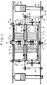
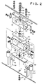
- a vibration proofing structure of the illustrated embodiment includes a first or lower base 10,which is formed with a slot-like through-hole 11.
- the vibration proofing structure also includes an elongated rail 12 provided separate from the base 10 and formed into a T-like shape in section.
- the rail 12 is formed at a central portion thereof with a vertically extending aperture 13.
- the aperture 13 is formed at a lower portion thereof with a circular depression (not shown), in which a bearing 14 is fitted.
- Reference numeral 15 designates a bolt which is downwardly inserted through the aperture 13 and of which a lower portion is inserted into the through-hole 11 of the first or lower base 10.
- the bolt 15 is threadedly fitted on a lower end thereof with a double nut 16,resulting in the rail 12 being mounted on the base 6 so that a longitudinal axis thereof may be rendered perpendicular to that of the through-hole 11 of the lower base 10.
- the bolt 15 is formed into a diameter smaller than a size of the through-hole 11 in a lateral direction thereof, so that it may be reciprocated in a longitudinal direction of the through-hole 15 therein. Also, such construction and arrangement permit the rail 12 to be rotated about the bearing 14 in a horizontal direction.
- the vibration proofing mechanism or structure of the illustrated embodiment also includes an elongated guide 17 which is formed of a plate-like material into a substantially T-shape in section of which an opening is defined at a bottom thereof, resulting in permitting the rail 12 to be fittedly received in the guide 17 through the opening.
- the guide 17 is provided at each of portions of a top thereof spaced from each other in a longitudinal direction thereof with a bolt hole 18.
- the vibration proofing structure of the illustrated embodiment further includes a tank 19 for a first or lower oil damper 20, which tank is formed into a shape like a rectangular cylinder and arranged so that a longitudinal axis thereof extends in the same direction as that of the guide 17.
- the tank 19, as shown in Fig. 1, is formed at a bottom thereof with bolt holes 21 in a manner to positionally correspond to the bolt holes 18 of the guide 17, so that bolts 22 are inserted into the bolt holes 18 and 21, resulting in the tank 19 being securely mounted on the guide 17.
- the tank 19 of the lower oil damper 20 is formed at a central portion of a top thereof with a slot-like aperture 23 of which a longitudinal axis extends in a longitudinal direction of the tank 19, as well as at each of portions of the top thereof spaced from each other in the longitudinal direction of the tank 19 with a small aperture 24, through which oil is fed to each of chambers defined on both sides in an interior of the tank 19. After the tank 19 is thus fed with oil, the apertures 24 each are closed with a screw.
- the tank 19 of the lower oil damper 20, as shown in Fig. 1, is provided therein with a pair of pistons 25, which are arranged in a row in the longitudinal direction of the tank 19 and connected to each other through a connection bar 26 interposedly arranged therebetween.
- connection bar 26 is threadedly mounted at a central portion thereof with a rod 27 in a manner to upwardly extend therefrom and then project through the aperture 23 from the tank 19.
- the tank 19 includes end plates mounted on both ends thereof, each of which is threadedly mounted thereon with a bolt 28 in a manner to horizontally outwardly extend therefrom.
- Reference numeral 29 designates a support of which a lower end is supportedly mounted on each of both ends of the rail 12 defined in the longitudinal direction thereof by means of bolts 30.
- the supports 29 each may be formed into a plate-like shape and are formed at an upper portion thereof with a hole, through which the bolt 28 is inserted. Then, the bolt 28 is threadedly mounted on a distal end thereof with a double nut 31.
- the tank 19 is securely mounted on the top thereof with a closing plate 32 to completely close the small apertures 24.
- the closing plate 32 is formed at a central portion thereof with an elongated slot-like aperture 33 of the same configuration as the slot-like aperture 23 in a manner to be positionally aligned with the aperture 23.
- the closing plate 32 mounted on the tank 19 of the lower oil damper is covered with an intermediate plate 34 formed into substantially the same configuration as the closing plate 32.
- the intermediate plate 34 is formed at a central portion thereof with an aperture 35, in which a bearing 36 is fitted, to thereby rotatably support an upper end of the rod 27 therein.
- the lower base 10 is formed at a portion thereof positioned outside each of the supports 29 with an aperture 37, through which a support 38 is vertically inserted at a lower end thereof.
- the supports 38 may be formed into a plate-like shape. Then, the supports 38 each are fixed at the lower end thereof to the lower base 10 by means of a double nut 39.
- the supports 38 each are formed at an upper portion thereof with an aperture 40 extending in a thickness direction thereof or in a horizontal direction, through which a rod 41 is inserted at one end or a proximal end thereof. Then, the rod 41 is mounted in the hole 40 by means of a pair of nuts 42 arranged in a manner to interpose the support 38 therebetween.
- the rod 41 is mounted on the other end or a distal end thereof with a pad 43 made of a rubber material, by virtue of which the rod 41 is abutted at the distal end thereof against an end surface of each of the intermediate plates 34.
- the vibration proofing mechanism or structure of the illustrated embodiment includes a second or upper oil damper 44, which is constructed in substantially the same manner as the first or lower oil damper 20 described above and mounted on the intermediate plate 34.
- the upper oil damper 44 includes a tank 45 which is integrally joined at a bottom to the intermediate plate 34 by means of bolts 46.
- the tank 45 as shown in Fig. 1, is provided therein with a pair of pistons 47, which are arranged in a row in a longitudinal direction of the tank 45 and connected to each other through a connection bar 48 interposedly arranged therebetween.
- connection bar 48 is threadedly mounted at a central portion thereof with a rod 49 in such a manner so as to upwardly extend therefrom and then upwardly outwardly project from the tank 45 through a slot-like aperture 50 formed at a top of the tank 45.
- the top of the tank 45 is formed at each of portions thereof spaced from each other in a longitudinal direction of the tank 45 with a small aperture 51, which is closed with a screw.
- the tank 45 of the second oil damper 44 is securely mounted on the top thereof with a closing plate 52.
- the closing plate 52 is formed at a central portion thereof with a slot-like aperture 53 so as to be aligned with the aperture 50 of the tank 45 and is provided thereon with a second or upper base 54.
- the second or upper base 54 is formed with an aperture 55 so as to be aligned with the aperture 50 of the tank 45 and the aperture 53 of the closing plate 52, so that the rod 49 is projected from an interior of the tank 45 through the apertures 50, 53 and 55 to an exterior of the vibration proofing structure.
- the aperture 55 of the second or upper base 54 is fitted therein with a bearing 56 through which the rod 49 is supportedly inserted and then a double nut 57 is threadedly fitted on an upper end of the rod 49.
- the tank 45 of the upper oil damper 44 includes a pair of end plates to each of which a bolt 58 is threadedly connected at one end thereof.
- Reference numeral 59 designate a support which may be formed into a plate-like shape and is arranged on each of both sides of the tank 45 of the upper oil damper 44.
- the supports 59 each are formed at a lower portion thereof with a through-hole via which the bolt 58 is inserted. Then, the bolt 58 is threadedly fitted on the other end thereof with a double nut 60, so that the support 59 is vertically mounted on each of both sides of the tank 45 so as to upwardly extend therefrom.
- the supports 59 each are arranged so as to be projected at an upper portion thereof from an aperture 61 formed through the upper base 54.
- the apertures 61 each are sealed with a rubber material 62 and the supports 59 each are threadedly fitted on an upper end thereof with a double nut 63, to thereby be securely joined to the upper base 54.
- a space of a predetermined interval is defined between the lower base 10 and the upper base 54 as shown in Fig. 1.
- the vibration proofing structure thus constructed is provided on both sides thereof with a pair of struts 64 for bearing a load downwardly applied to the upper base 54. More particularly, the struts 64 each are vertically mounted on the lower base 10 by inserting a lower portion of the strut 64 through an aperture 65 formed via the lower base 10 and threadedly fitting a double nut 66 on a lower end of the strut 64.
- the strut 64 is provided at an upper portion thereof with a cylinder 67 in which a rubber member 68 is fitted.
- a suitable spring member such as a leaf spring or the like is received in the cylinder 67 in a manner to be arranged on the rubber member 68, followed by mounting a hemispherical member 69 on a top of the cylinder 67.
- the hemispherical member 69 is kept contacted with a lower surface of the second or upper base 54.
- vibration to, for example, the lower base 10 is to cause the tank 19 of the lower oil damper 20 mounted on the lower base 10 to be vibrated. Even when the tank 19 of the lower oil damper 20 is vibrated, oil in the tank 19 of the lower oil damper 20 absorbs the vibration to prevent it from being transmitted to the rod 27. Nevertheless, the oil fails to fully prevent transmission of the vibration to the rod 27. A portion of the vibration which is thus slightly transmitted to the rod 27 causes the tank 45 of the upper oil damper 44 to be vibrated.
- the rods 41 of the supports 38 act to push back the vibration transmitted to the upper oil damper 44 in an opposition direction, to thereby substantially reduce momentum of kinetic inertia energy caused by the instantaneous impact by a car which is running.
- Vibration of the tank 45 of the upper oil damper 44 is effectively absorbed by oil in the tank 45 of the damper 44, to thereby be prevented from being transmitted to the rod 49.
- vibration applied to the lower base 10 is substantially prevented from being transmitted to the upper base 54 to which the rod 49 is connected.
- vibration applied to the upper base 54 is absorbed in the same manner as the above, resulting in being substantially prevented from being transmitted to the lower base 10.
- Vibration in an oblique direction is applied to the vibration proofing structure depending on a place at which the structure is used and conditions under which it is used.
- the vibration proofing structure as described above, is constructed so that the oil dampers 20 and 44 rotate relative to each other and relative to the upper and lower bases 10 and 54.
- application of oblique vibration to the vibration proofing structure causes relative rotation between the oil dampers and/or between the oil dampers and the bases, so that application of torsion to the structure may be effectively prevented, to thereby eliminate damage to the structure and an adverse effect on a vibration proofing function of the structure.
- the nut 31, 42 and 60 by which the supports 29, 38 and 59 are respectively fastened are loosened.
- any one of the nuts 31 is tightened to permit the guide 17 and tank 19 to be moved along the rail 12 in the longitudinal direction of the vibration proofing structure, resulting in aligning the bolt 15 for fixing the rail 12 and a center of the tank 19 with each other.
- the nuts 31 are firmly tightened while keeping both aligned with each other, to thereby stationarily hold the tank 19 and the like.
- the rod 27, the piston 25 and the like are moved in the longitudinal direction of the structure through the intermediate plate while tightening the nut 42 of one of the supports 38, to thereby position the rod 27 at the center of the tank 19, followed by tightening the nuts 47 to fix the rod 27 at the center of the tank 19.
- the upper tank 45 is automatically fixed at a predetermined position.
- the upper base 54 is moved in the longitudinal direction of the structure to position the rod 49 at the center of the tank 45 of the upper oil damper 44 and then the nuts 63 are tightened to fix the upper base 54 with respect to the tank 45.
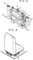
- the vibration proofing structure of the illustrated embodiment constructed as described above may be widely applied to a variety of fields such as a construction, various kinds of machines and the like. Now, application of the vibration proofing structure of the illustrated embodiment to a seat for a car, a construction equipment or the like will be described hereinafter with reference to Fig. 4.
- FIG. 4 four such vibration proofing structures are arranged in the form of a rectangular configuration between the lower base 10 and the upper base 54.
- a weight of the upper base 54 and load applied to the upper base 54 are substantially borne by the struts 64 and vibration in the vertical direction is absorbed by an elastic cushioning material such as the rubber member 68 of each of the struts 64.
- the above-descried vibration in the lateral direction constitutes vibration in the longitudinal direction with respect to second two vibration proofing structures arranged perpendicular to arrangement of the above-described first two vibration proofing structures juxtaposed to each other in the longitudinal direction.
- the vibration is substantially absorbed by the first two vibration proofing structures as described above, to thereby be minimized.
- the second two vibration proofing structures each are so operated that only the lower base 10 is moved by a slight distance in the lateral direction without moving the components of the structure except the base 10 while keeping the bolt 15 fitted in the through-hole 11 of the base 10, to thereby prevent the minimized vibration from being transmitted to the upper base 54.
- vibration to the lower base 10 is carried out in the lateral and longitudinal directions of the base 10, as well as in oblique directions thereof.
- first two vibration proofing structures and second two ones are transmitted to the first two vibration proofing structures and second two ones.
- the first and second vibration proofing structures each function to absorb the components in such a manner as described above, respectively, to thereby substantially prevent the vibration from being transmitted to the upper base 54.
- the vibration proofing structure of the illustrated embodiment is so constructed that the rail 12, guide 17 and lower tank 19 are integrally rotatable with respect to the lower base 10. Also, the upper tank 45 and intermediate plate 34 are rotatable with respect to the rail 12, guide 17 and lower tank 19. Further, the upper tank 45 is rotatable with respect to the upper base 54.
- Such construction of the vibration proofing structure when vibration of a large magnitude is obliquely applied to the lower substrate 10, permits upper and lower sections of the structure to rotate relative to each other at three rotatable positions described above, to thereby prevent torsion from being applied to the vibration proofing structure.
- the vibration proofing structure of the embodiment ensures safety in operation and effectively exhibits a satisfactory vibration proofing function.
- Results of a test made on the seat shown in Fig. 4 for measuring vibration proofing performance of the vibration proofing structure of the illustrated embodiment are shown in Table 1.
- the test was carried out using three inspection units and in such a manner that an inspection needle of each of the units is abutted at a tip end thereof against each of the lower base 10, intermediate plate 34 and upper base 54.
- a degree of transmission of impact force applied to the lower substrate 10 to each of the inspection units was measured. Numerical values indicated in Table 1 are round. Impact Force Applied to Lower Base 10 (kg) Impact Force Transmitted to Intermediate Plate 34 (kg) Impact Force Transmitted to Upper Base 54 (g) 100 80 800 250 100 80 300 120 80 450 150 90
- a vertical-type oil damper which may be incorporated between the lower base 10 and the upper base 54 is illustrated.
- the upper base 54 is formed with an aperture 70, through which a rod 71 is upwardly inserted.
- upper and lower nuts 72 are threadedly fitted on the rod 71 so as to interpose the upper base 54 therebetween, resulting in the rod 71 being fixed to the upper base 54.
- the rod 71 is threadedly fitted thereon with a adjustment nut 73 at a position below the lower nut 72. Further, the rod 71 is snugly fitted on a portion thereof positioned under the adjustment nut 73 with a pipe 74.
- the pipe 74 is fitted thereon with a cap-like ring 75, which is then threadedly fitted in a disc-like lid 76.
- the lid 76 is arranged so as to cover an upper end of a cylindrical tank 77.
- the tank 77 is provided at a central region therein with a piston 78, which is fittedly mounted on a lower portion of the rod 71.
- the rod 71 is threadedly fitted thereon with upper and lower nuts 79 so as to tightly interpose the piston 78 therebetween, to thereby securely hold the piston 78 on the rod 71.
- the piston 78 is formed with vertically extending through-holes 80 of a small size which act as an oil passage means.
- Reference numeral 81 designates a bowl-like cap arranged between the pipe 74 and the piston 78 so as to cover the through-holes 80.
- Reference numeral 82 designates a coiled spring interposedly arranged between the cap 81 and the piston 78. Downward movement of the adjustment nut 73 to forcedly press a lower end of the cap 81 against the piston 78 through the pipe 74 prevents oil from flowing through the through-holes 80. When the adjustment nut 73 is slightly raised, a gap of a slight distance is formed between the cap 81 and the piston 78 to permit a slight amount of oil to vertically flow via the through-holes 80.
- the tank 77 used under such conditions is provided at a bottom thereof with a substantially hemispherical member 84 through a cushioning member 83 made of rubber or the like, so that the member 84 is abutted at a lower distal end thereof against the lower base 10.
- the oil damper shown in Fig. 5 may be used in combination with a strut shown in Fig. 6.
- the strut shown in Fig. 6 is arranged between the lower base 10 and the upper base 54 and includes a hollow cylinder 85 in which an elastic cushioning member (not shown) such as a leaf spring or the like is incorporated and a hemispherical member 86 mounted on a top of the cylinder 85.
- an elastic cushioning member such as a leaf spring or the like
- a hemispherical member 86 mounted on a top of the cylinder 85.
- a suitable number of oil dampers shown in Fig. 5 and a suitable number of struts shown in Fig. 6 are used in combination, wherein the struts function to substantially bear a weight and the oil dampers function to substantially absorb vibration.
- a vertical-type oil damper shown in Fig. 7 may be substituted for that of Fig. 5.
- the oil damper of Fig. 7 includes a tank 87 of which a bottom plate 88 is fixed on the lower base 10 by means of bolt-nut combinations.
- a piston 91 is supported on a coiled spring 92 arranged between the bottom plate 88 and the piston 91.
- the piston 91 is fitted on a lower portion of a rod 93 and then securely held thereon by means of upper and lower nuts 94 threadedly fitted on the rod 93 so as to interpose the piston 91 therebetween.
- the rod 93 is arranged so as to be upwardly projected at an upper portion thereof through a center of each of a ring 95 and a lid 96 arranged for covering an upper end of the tank 87 from the tank 87.
- the rod 93 is mounted on an upper end thereof with a hemispherical member 97, which is abutted against a lower surface of the upper base 54.
Landscapes
- Engineering & Computer Science (AREA)
- General Engineering & Computer Science (AREA)
- Mechanical Engineering (AREA)
- Aviation & Aerospace Engineering (AREA)
- Transportation (AREA)
- Physics & Mathematics (AREA)
- Acoustics & Sound (AREA)
- Structural Engineering (AREA)
- Civil Engineering (AREA)
- Life Sciences & Earth Sciences (AREA)
- Geology (AREA)
- Buildings Adapted To Withstand Abnormal External Influences (AREA)
- Vibration Prevention Devices (AREA)
- Seats For Vehicles (AREA)
- Fluid-Damping Devices (AREA)
Description
| Impact Force Applied to Lower Base 10 (kg) | Impact Force Transmitted to Intermediate Plate 34 (kg) | Impact Force Transmitted to Upper Base 54 (g) |
| 100 | 80 | 800 |
| 250 | 100 | 80 |
| 300 | 120 | 80 |
| 450 | 150 | 90 |
Claims (6)
- A vibration proofing structure comprising:characterised by:a first base (10);a first oil damper (20) mounted on said first base (10);said first oil damper (20) including a first tank (19) mounted on said first base (10), first pistons (25) arranged in said first tank (19), and a first rod (27) having a first end and a second end, said first end of said first rod (27) being mounted on said first pistons (25) so as to render an axis of said first rod (27) perpendicular to a longitudinal axis of said first pistons (25), said second end of said first rod (27) outwardly extending from said first tank;a second oil damper (44) including a second tank (45), second pistons (47) arranged in said second tank (45), and a second rod (49) having a first end and a second end, said first end of said second rod (49) being mounted on said second pistons (47) so as to render an axis of said second rod (49) perpendicular to a longitudinal axis of said second pistons (47), said second end of said second rod (49) outwardly extending from said second tank (45); anda second base (54) on which the second end of said second rod (49) is mounted;said first and second oil dampers (20,44) being juxtaposed to each other;said second end of said first (27) rod being connected to said second tank (45) of said second oil damper (44), and said first rod (27) of said first oil damper (20) being connected to said second tank (45) of said second oil damper (44) so as to permit said first and second oil dampers (20,44) to rotate relative to each other.
- A vibration proofing structure as defined in Claim 1, wherein said first tank (19) of said first oil damper (20) is mounted on said first base (10) so as to permit said first oil damper (20) and first base (10) to rotate relative to each other.
- A vibration proofing structure as defined in Claim 1 or 2, wherein said second end of said second rod (49) is mounted on said second base (54) so as to permit said second oil damper (44) and second base (54) to rotate relative to each other.
- A vibration proofing structure as defined in Claim 1 further comprising an intermediate plate (34) fixed on said second oil damper (44) so as to be arranged between said first oil damper (20) and said second oil damper (44) which are connected to each other so as to rotate relative to each other;said intermediate plate (34) being provided with a bearing (36) for rotatably supporting said first rod (27) of said first oil damper (20);supports (38) each mounted on said first base (10) so as to extend therefrom and positioned on each of both sides of said first oil damper (20) so as to be spaced at a small interval therefrom; androd members (41) each mounted on each of said supports (38) so as to inwardly extend therefrom in a direction parallel to a direction of sliding of said pistons (25), to thereby connect said intermediate plate (34) and each of said supports (38) to each other therethrough in a non-fixed manner.
- A vibration proofing structure as defined in any one of Claims 1-4, further comprising plural struts (64) for substantially bearing weight of said second base (54) and load downwardly applied to said second base (54),said struts each being vertically mounted on said first base, anda hemispherical member which is elastically supported on the top of each of said struts,said hemispherical member being kept contacted with a lower surface of said second base.
- A vibration proofing structure as defined in Claim 5, further comprising plural vertical-type oil dampers which are incorporated between said first base and said second base,said vertical-type oil dampers being fixed to one of said second and first bases, anda hemispherical member on the top of each of said vertical-type oil dampers,said hemispherical member being kept contacted with the other one of the two bases which does not fix the vertical-type oil dampers.
Priority Applications (1)
| Application Number | Priority Date | Filing Date | Title |
|---|---|---|---|
| EP97202788A EP0849496B1 (en) | 1993-05-14 | 1994-05-10 | Vibration Proofing Structure |
Applications Claiming Priority (4)
| Application Number | Priority Date | Filing Date | Title |
|---|---|---|---|
| JP14712293 | 1993-05-14 | ||
| JP147122/93 | 1993-05-14 | ||
| JP12795794A JP3666028B2 (en) | 1993-05-14 | 1994-05-06 | Anti-vibration mechanism |
| JP127957/94 | 1994-05-06 |
Related Child Applications (1)
| Application Number | Title | Priority Date | Filing Date |
|---|---|---|---|
| EP97202788A Division EP0849496B1 (en) | 1993-05-14 | 1994-05-10 | Vibration Proofing Structure |
Publications (2)
| Publication Number | Publication Date |
|---|---|
| EP0625649A1 EP0625649A1 (en) | 1994-11-23 |
| EP0625649B1 true EP0625649B1 (en) | 1998-04-15 |
Family
ID=26463770
Family Applications (2)
| Application Number | Title | Priority Date | Filing Date |
|---|---|---|---|
| EP19940303346 Expired - Lifetime EP0625649B1 (en) | 1993-05-14 | 1994-05-10 | Vibration proofing structure |
| EP97202788A Expired - Lifetime EP0849496B1 (en) | 1993-05-14 | 1994-05-10 | Vibration Proofing Structure |
Family Applications After (1)
| Application Number | Title | Priority Date | Filing Date |
|---|---|---|---|
| EP97202788A Expired - Lifetime EP0849496B1 (en) | 1993-05-14 | 1994-05-10 | Vibration Proofing Structure |
Country Status (3)
| Country | Link |
|---|---|
| EP (2) | EP0625649B1 (en) |
| JP (1) | JP3666028B2 (en) |
| DE (2) | DE69409573T2 (en) |
Families Citing this family (19)
| Publication number | Priority date | Publication date | Assignee | Title |
|---|---|---|---|---|
| JP3803369B2 (en) * | 1994-01-25 | 2006-08-02 | マイナス ケー テクノロジー,インコーポレイテッド | Vibration isolator |
| DE4411470B4 (en) * | 1994-04-01 | 2004-09-02 | Linde Ag | Industrial truck with a platform |
| JP4946359B2 (en) * | 2006-11-01 | 2012-06-06 | 美和ロック株式会社 | Spring damper |
| KR101231653B1 (en) * | 2011-05-30 | 2013-02-14 | 김해남 | Earthquake Proof Apparatus for a Structure |
| GB2494884B (en) * | 2011-09-21 | 2016-01-20 | Palletforce Plc | Apparatus and method for the identification and weighing of cargo |
| KR101227947B1 (en) * | 2012-10-09 | 2013-01-30 | (주)테크윈시스템 | Seismic proof switchgear and controlgear |
| JP6122881B2 (en) * | 2015-01-14 | 2017-04-26 | 株式会社畑鉄工所 | Pressure buffer device for rotary powder compression molding apparatus and rotary powder compression molding apparatus provided with the same |
| CN107091296A (en) * | 2017-06-05 | 2017-08-25 | 长江师范学院 | Plant equipment clamps change type oscillation damping method |
| CN107218222A (en) * | 2017-06-07 | 2017-09-29 | 河南多普电子科技有限公司 | A kind of intelligent automatic control screw refrigerating compressor |
| CN107697854B (en) * | 2017-11-03 | 2024-07-12 | 安徽合力股份有限公司 | Vibration-damping adjustable suspension type standing board for standing forklift |
| CN108773302A (en) * | 2018-07-11 | 2018-11-09 | 深圳达芬奇创新科技有限公司 | A kind of buffer unit of automotive seat |
| JP6469291B1 (en) * | 2018-07-17 | 2019-02-13 | Kyb株式会社 | Fall prevention device |
| CN109114158B (en) * | 2018-08-20 | 2020-11-24 | 常熟理工学院 | Combined vibration damper for car |
| CN110056595B (en) * | 2019-05-11 | 2021-12-31 | 泉州市博汉机械股份有限公司 | Limiting shock absorber structure |
| CN112456048A (en) * | 2020-11-26 | 2021-03-09 | 浙江东腾智能装备有限公司 | Ground rail flat car capable of automatically lifting and rotating platform |
| JP7479304B2 (en) * | 2021-01-07 | 2024-05-08 | 日立Geニュークリア・エナジー株式会社 | Support structure for piping using viscoelastic dampers |
| CN114918979B (en) * | 2022-06-30 | 2024-04-26 | 上海擎朗智能科技有限公司 | Floating pallet and robot |
| CN115492894B (en) * | 2022-08-04 | 2023-05-23 | 哈尔滨工程大学 | High-efficiency vibration-absorbing base supported by chain-type panel liquid bladders |
| KR200499043Y1 (en) * | 2022-11-16 | 2025-04-11 | 주식회사 보고코퍼레이션 | Supporting device of water tank and Method of installing thereof |
Family Cites Families (6)
| Publication number | Priority date | Publication date | Assignee | Title |
|---|---|---|---|---|
| US2312718A (en) * | 1941-04-23 | 1943-03-02 | Haroutium K Kouyoumjian | Shock absorber |
| US2760552A (en) * | 1952-11-13 | 1956-08-28 | Frederick J Decker | Pneumatic seat |
| FR1362687A (en) * | 1963-04-26 | 1964-06-05 | Vibrachoc Sa | Variable linkage, servo device and damping device for devices such as gyro-compasses including application |
| US3625466A (en) * | 1970-08-20 | 1971-12-07 | Marshall Research & Dev Corp | Vibration isolator |
| JPS60184736A (en) * | 1984-02-29 | 1985-09-20 | Sanwa Tekki Corp | Fixed hydraulic vibration insulator |
| JP2676559B2 (en) * | 1989-10-23 | 1997-11-17 | 正彦 池田 | Anti-vibration mechanism |
-
1994
- 1994-05-06 JP JP12795794A patent/JP3666028B2/en not_active Expired - Lifetime
- 1994-05-10 DE DE1994609573 patent/DE69409573T2/en not_active Expired - Fee Related
- 1994-05-10 DE DE1994630394 patent/DE69430394T2/en not_active Expired - Fee Related
- 1994-05-10 EP EP19940303346 patent/EP0625649B1/en not_active Expired - Lifetime
- 1994-05-10 EP EP97202788A patent/EP0849496B1/en not_active Expired - Lifetime
Also Published As
| Publication number | Publication date |
|---|---|
| DE69430394T2 (en) | 2003-10-23 |
| JPH0727171A (en) | 1995-01-27 |
| DE69430394D1 (en) | 2002-05-16 |
| EP0625649A1 (en) | 1994-11-23 |
| EP0849496B1 (en) | 2002-04-10 |
| JP3666028B2 (en) | 2005-06-29 |
| EP0849496A3 (en) | 1999-02-10 |
| EP0849496A2 (en) | 1998-06-24 |
| DE69409573T2 (en) | 1998-12-24 |
| DE69409573D1 (en) | 1998-05-20 |
Similar Documents
| Publication | Publication Date | Title |
|---|---|---|
| EP0625649A1 (en) | Vibration proofing structure | |
| US4351556A (en) | Seat suspension | |
| EP1487609B1 (en) | Tuned damped absorber support | |
| DE19959839A1 (en) | Pneumatic spring with vibration damper for motor vehicle has connecting bearing installed in region of generated surface of cylinder tube and is circular in construction and equipped with sealing ring sealing off spring chamber | |
| JP6032322B1 (en) | Vehicle restraint device | |
| JPH0244583Y2 (en) | ||
| US5549282A (en) | Vibration proofing structure | |
| EP0344415B1 (en) | Mounting system for the engine of an automotive vehicle | |
| US20070062293A1 (en) | Inertial mass guided single axis vibration test machine | |
| DE10024164A1 (en) | Device for torque support of a Bernner machine | |
| EP1080970A1 (en) | Vibration-isolation supporting structure for engine | |
| CN117053970B (en) | Damping force testing device of shock absorber | |
| JP2676559B2 (en) | Anti-vibration mechanism | |
| CN219904043U (en) | Shock-absorbing bracket for automobile engine | |
| JPH0953684A (en) | Vibration isolating device | |
| JPH07277290A (en) | Aircraft engine mounting equipment | |
| KR100461449B1 (en) | Engine mounting apparatus | |
| KR20080102565A (en) | 쇽 Jig for absorber damping force measuring instrument | |
| DE19959842A1 (en) | Pneumatic spring for vehicle with running gear has circular connecting bearing on running gear and installed in region of generated surface of reservoir tube and with sealing ring sealing off spring chamber | |
| KR100199744B1 (en) | Jig for Measuring Damping Force of Automotive Shock Absorber | |
| DE4213043C2 (en) | Hydropneumatic damper spring element | |
| JP2736533B2 (en) | Floor seismic isolation device | |
| CN224095064U (en) | Stay wire type displacement measuring device and measuring assembly thereof | |
| JP5880656B2 (en) | Vehicle restraint device | |
| KR20010065851A (en) | Mounting jig for spring characteristics test of engine mount |
Legal Events
| Date | Code | Title | Description |
|---|---|---|---|
| PUAI | Public reference made under article 153(3) epc to a published international application that has entered the european phase |
Free format text: ORIGINAL CODE: 0009012 |
|
| AK | Designated contracting states |
Kind code of ref document: A1 Designated state(s): DE FR GB IT SE |
|
| 17P | Request for examination filed |
Effective date: 19950304 |
|
| 17Q | First examination report despatched |
Effective date: 19960116 |
|
| RAP1 | Party data changed (applicant data changed or rights of an application transferred) |
Owner name: IKEDA, KIYOKO |
|
| RIN1 | Information on inventor provided before grant (corrected) |
Inventor name: IKEDA, MASAHIKO |
|
| GRAG | Despatch of communication of intention to grant |
Free format text: ORIGINAL CODE: EPIDOS AGRA |
|
| GRAG | Despatch of communication of intention to grant |
Free format text: ORIGINAL CODE: EPIDOS AGRA |
|
| GRAG | Despatch of communication of intention to grant |
Free format text: ORIGINAL CODE: EPIDOS AGRA |
|
| GRAH | Despatch of communication of intention to grant a patent |
Free format text: ORIGINAL CODE: EPIDOS IGRA |
|
| GRAH | Despatch of communication of intention to grant a patent |
Free format text: ORIGINAL CODE: EPIDOS IGRA |
|
| GRAA | (expected) grant |
Free format text: ORIGINAL CODE: 0009210 |
|
| AK | Designated contracting states |
Kind code of ref document: B1 Designated state(s): DE FR GB IT SE |
|
| DX | Miscellaneous (deleted) | ||
| REF | Corresponds to: |
Ref document number: 69409573 Country of ref document: DE Date of ref document: 19980520 |
|
| ITF | It: translation for a ep patent filed | ||
| ET | Fr: translation filed | ||
| PLBE | No opposition filed within time limit |
Free format text: ORIGINAL CODE: 0009261 |
|
| STAA | Information on the status of an ep patent application or granted ep patent |
Free format text: STATUS: NO OPPOSITION FILED WITHIN TIME LIMIT |
|
| 26N | No opposition filed | ||
| REG | Reference to a national code |
Ref country code: GB Ref legal event code: IF02 |
|
| PGFP | Annual fee paid to national office [announced via postgrant information from national office to epo] |
Ref country code: GB Payment date: 20030422 Year of fee payment: 10 |
|
| PG25 | Lapsed in a contracting state [announced via postgrant information from national office to epo] |
Ref country code: GB Free format text: LAPSE BECAUSE OF NON-PAYMENT OF DUE FEES Effective date: 20040510 |
|
| GBPC | Gb: european patent ceased through non-payment of renewal fee |
Effective date: 20040510 |
|
| PGFP | Annual fee paid to national office [announced via postgrant information from national office to epo] |
Ref country code: DE Payment date: 20050531 Year of fee payment: 12 |
|
| PGFP | Annual fee paid to national office [announced via postgrant information from national office to epo] |
Ref country code: FR Payment date: 20051129 Year of fee payment: 12 |
|
| PGFP | Annual fee paid to national office [announced via postgrant information from national office to epo] |
Ref country code: SE Payment date: 20051130 Year of fee payment: 12 |
|
| PG25 | Lapsed in a contracting state [announced via postgrant information from national office to epo] |
Ref country code: SE Free format text: LAPSE BECAUSE OF NON-PAYMENT OF DUE FEES Effective date: 20060511 |
|
| PGFP | Annual fee paid to national office [announced via postgrant information from national office to epo] |
Ref country code: IT Payment date: 20060531 Year of fee payment: 13 |
|
| PG25 | Lapsed in a contracting state [announced via postgrant information from national office to epo] |
Ref country code: DE Free format text: LAPSE BECAUSE OF NON-PAYMENT OF DUE FEES Effective date: 20061201 |
|
| EUG | Se: european patent has lapsed | ||
| REG | Reference to a national code |
Ref country code: FR Ref legal event code: ST Effective date: 20070131 |
|
| PG25 | Lapsed in a contracting state [announced via postgrant information from national office to epo] |
Ref country code: FR Free format text: LAPSE BECAUSE OF NON-PAYMENT OF DUE FEES Effective date: 20060531 |
|
| PG25 | Lapsed in a contracting state [announced via postgrant information from national office to epo] |
Ref country code: IT Free format text: LAPSE BECAUSE OF NON-PAYMENT OF DUE FEES Effective date: 20070510 |