EP0624744A1 - Vibration dampered duckbill valve - Google Patents
Vibration dampered duckbill valve Download PDFInfo
- Publication number
- EP0624744A1 EP0624744A1 EP94302469A EP94302469A EP0624744A1 EP 0624744 A1 EP0624744 A1 EP 0624744A1 EP 94302469 A EP94302469 A EP 94302469A EP 94302469 A EP94302469 A EP 94302469A EP 0624744 A1 EP0624744 A1 EP 0624744A1
- Authority
- EP
- European Patent Office
- Prior art keywords
- valve
- vibration
- valve body
- lip portions
- natural frequency
- Prior art date
- Legal status (The legal status is an assumption and is not a legal conclusion. Google has not performed a legal analysis and makes no representation as to the accuracy of the status listed.)
- Granted
Links
Images


Classifications
-
- F—MECHANICAL ENGINEERING; LIGHTING; HEATING; WEAPONS; BLASTING
- F16—ENGINEERING ELEMENTS AND UNITS; GENERAL MEASURES FOR PRODUCING AND MAINTAINING EFFECTIVE FUNCTIONING OF MACHINES OR INSTALLATIONS; THERMAL INSULATION IN GENERAL
- F16K—VALVES; TAPS; COCKS; ACTUATING-FLOATS; DEVICES FOR VENTING OR AERATING
- F16K15/00—Check valves
- F16K15/14—Check valves with flexible valve members
- F16K15/144—Check valves with flexible valve members the closure elements being fixed along all or a part of their periphery
- F16K15/147—Check valves with flexible valve members the closure elements being fixed along all or a part of their periphery the closure elements having specially formed slits or being of an elongated easily collapsible form
-
- F—MECHANICAL ENGINEERING; LIGHTING; HEATING; WEAPONS; BLASTING
- F16—ENGINEERING ELEMENTS AND UNITS; GENERAL MEASURES FOR PRODUCING AND MAINTAINING EFFECTIVE FUNCTIONING OF MACHINES OR INSTALLATIONS; THERMAL INSULATION IN GENERAL
- F16K—VALVES; TAPS; COCKS; ACTUATING-FLOATS; DEVICES FOR VENTING OR AERATING
- F16K15/00—Check valves
- F16K15/14—Check valves with flexible valve members
- F16K15/144—Check valves with flexible valve members the closure elements being fixed along all or a part of their periphery
- F16K15/147—Check valves with flexible valve members the closure elements being fixed along all or a part of their periphery the closure elements having specially formed slits or being of an elongated easily collapsible form
- F16K15/1471—Check valves with flexible valve members the closure elements being fixed along all or a part of their periphery the closure elements having specially formed slits or being of an elongated easily collapsible form slits arranged along multiple axes
-
- Y—GENERAL TAGGING OF NEW TECHNOLOGICAL DEVELOPMENTS; GENERAL TAGGING OF CROSS-SECTIONAL TECHNOLOGIES SPANNING OVER SEVERAL SECTIONS OF THE IPC; TECHNICAL SUBJECTS COVERED BY FORMER USPC CROSS-REFERENCE ART COLLECTIONS [XRACs] AND DIGESTS
- Y10—TECHNICAL SUBJECTS COVERED BY FORMER USPC
- Y10T—TECHNICAL SUBJECTS COVERED BY FORMER US CLASSIFICATION
- Y10T137/00—Fluid handling
- Y10T137/0318—Processes
- Y10T137/0324—With control of flow by a condition or characteristic of a fluid
- Y10T137/0379—By fluid pressure
-
- Y—GENERAL TAGGING OF NEW TECHNOLOGICAL DEVELOPMENTS; GENERAL TAGGING OF CROSS-SECTIONAL TECHNOLOGIES SPANNING OVER SEVERAL SECTIONS OF THE IPC; TECHNICAL SUBJECTS COVERED BY FORMER USPC CROSS-REFERENCE ART COLLECTIONS [XRACs] AND DIGESTS
- Y10—TECHNICAL SUBJECTS COVERED BY FORMER USPC
- Y10T—TECHNICAL SUBJECTS COVERED BY FORMER US CLASSIFICATION
- Y10T137/00—Fluid handling
- Y10T137/7722—Line condition change responsive valves
- Y10T137/7837—Direct response valves [i.e., check valve type]
- Y10T137/785—With retarder or dashpot
-
- Y—GENERAL TAGGING OF NEW TECHNOLOGICAL DEVELOPMENTS; GENERAL TAGGING OF CROSS-SECTIONAL TECHNOLOGIES SPANNING OVER SEVERAL SECTIONS OF THE IPC; TECHNICAL SUBJECTS COVERED BY FORMER USPC CROSS-REFERENCE ART COLLECTIONS [XRACs] AND DIGESTS
- Y10—TECHNICAL SUBJECTS COVERED BY FORMER USPC
- Y10T—TECHNICAL SUBJECTS COVERED BY FORMER US CLASSIFICATION
- Y10T137/00—Fluid handling
- Y10T137/7722—Line condition change responsive valves
- Y10T137/7837—Direct response valves [i.e., check valve type]
- Y10T137/7879—Resilient material valve
- Y10T137/788—Having expansible port
- Y10T137/7882—Having exit lip
Definitions
- the present invention relates to a duckbill check valve for use in a flow path for permitting relatively free flow of fluid in the flow path in a first direction from a first to a second end of the check valve and for preventing fluid flow in the path in a second opposite direction. More particularly, the present invention relates to a duckbill check valve having a construction which limits the vibration of lips forming the valve in order to prevent the production of whistling sounds during fluid flow through the valve.
- Duckbill valves are widely used to control fluid flow in a variety of devices.
- the structure of duckbill valves typically includes a pair of substantially planar lip portions which converge toward each other from a first to a second end of the valve.
- the lip portions are joined at lateral edges thereof by side walls such that the lip portions and side walls define a fluid flow path therethrough.
- the valve is typically formed of an elastomeric material and the lip portions are formed as thin highly flexible members which provide a low resistance to forward flow through the valve while producing a positive closing force for closing a slit at the second end of the valve to prevent reverse flow through the valve.
- valve which controls fluid flow in a desired direction and which does so without producing undesirable noise.
- valve which includes means for controlling noise related to vibrations of resilient portions of the valve in order to avoid production of noise during use of the valve.
- the present invention provides an anti-whistling duckbill check valve for use in a fluid flow path for permitting relatively free flow of fluid in the path in a first direction from a first to a second end of the valve and for preventing fluid flow in the path in a second opposite direction.
- the valve comprises a resilient valve body for controlling fluid flow, and a vibration dampener supported on the valve body for dampening a vibrating movement of the valve body during fluid flow past the valve.
- the check valve includes a base portion defining a longitudinal axis for the valve.
- First and second lip portions are supported by the base portion and extend in converging relationship toward each other to form a fluid flow passage through the valve.
- a slit is defined at the second end of the valve to form an opening for permitting fluid flow out of the flow passage.
- Vibration dampening means are located on each of the lip portions spaced from lateral edges thereof.
- the vibration dampening means may be in the form of ribs extending longitudinally along the lip portions wherein the depth of the ribs, as measured in a direction perpendicular to the slit, decreases at a substantially constant rate from the second end toward the first end of the valve.
- the vibration dampening elements increase the mass of the lip portions to substantially alter the vibration characteristics thereof.
- the vibration dampening elements form vibrating members having a natural frequency substantially equal to and out of phase with the lip portions such that audible noise producing vibrations of the lip portions are cancelled out by vibrations of the dampening means.
- vibration dampening elements control the movement of the lip portions without adversely affecting the beneficial characteristics of the duckbill valve including the ability to quickly open at low pressures, as well as provide a positive closure of the slit during reverse flow conditions.
- the anti-whistling duckbill check valve 10 of the present invention includes a base portion 12 and a regulator portion 14.
- the base portion 12 is adapted to support the valve 10 in a fluid flow line and further provides a support structure for supporting the regulator portion 14.
- the base portion is defined by inner and outer wall portions 16, 18 wherein each wall portion 16, 18 has a substantially circular cross-section which decreases in diameter from a first end 20 toward a second end 22 of the valve 10.
- the inner wall 16 is provided with a substantially cylindrical portion 24 which may facilitate attachment of the valve 10 to a fluid flow line
- the outer wall 18 is provided with a substantially cylindrical portion 26 which may facilitate mounting the outer portion of the valve 10 to an interior wall of a fluid flow line wherein adjacent tapered portions 17, 19 of the walls 16, 18 facilitate movement of the fluid flow lines into contact with the cylindrical portions 24, 26.
- a flange 28 extends radially outwardly from the base portion 12 at the first end 20 of the valve for further facilitating mounting of the valve to a fluid line or support surface.
- the flange 28 is formed as an annular member and defines, along with the other base portion structure, a central longitudinal axis 30 for the valve 10.
- the regulator portion 14 includes first and second lip portions 32, 34.
- the lip portions 32, 34 define respective substantially planar inner walls 36, 38 and substantially planar outer walls 40, 42 such that the lip portions 32, 34 are formed as substantially planar members.
- the lip portions 32, 34 are joined by curved side walls 44, 46 which extend between lateral edges of the lip portions 32, 34 such that the lip portions 32, 34 and side walls 44, 46 define a fluid flow passage 48 through the valve 10.
- a slit 50 is formed between the lip portions 32, 34 at the second end 22 and provides an opening for permitting fluid flow out of the flow passage 48.
- the lip portions 32, 34 each have a thickness between respective inner and outer walls 36, 40 and 38, 42 which is less than approximately 1/20 of the width of the lip portions, as measured in a direction parallel to the direction of the length of the slit 50.
- the lip portions 32, 34 and side walls 44, 46, as well as the base portion 12 is formed of an elastomeric material such that the lip portions 32, 34 are formed as resilient highly flexible members which permit easy opening of the slit 50 for forward flow of fluids through the flow passage 48 in a direction from the first end 20 to the second end 22 of the valve 10.
- the resilient lip portions 32, 34 also provide for positive closure of the slit 50 during reverse flow conditions.
- the valve of the present invention is provided with vibration dampening means in the form of first and second ribs 52, 54 which extend from an upstream location, for example adjacent to the base portion 12, toward a downstream location adjacent to the second end 22 of the valve 10.
- each of the ribs 52, 54 are defined by opposing pairs of lateral walls 56, 58 and 60, 62 which are connected by respective connecting walls 64, 66.
- each of the ribs 52, 54 include an inner wall 65, 67 located in spaced relation to respective lip outer walls 40, 42.
- the ribs 52, 54 define cantilever members supported by the lip portions 32, 34 wherein the ribs 52, 54 are configured to have a characteristic natural frequency which substantially matches or is equal to the natural frequency of the lip portions 32, 34 as the lip portions 32, 34 vibrate at a frequency in the audible frequency range.
- the particular natural frequency selected for the ribs 52, 54 may be controlled by selecting appropriate values for the mass (M) of the ribs 52, 54, the bending stiffness (S) of the connection of the ribs 52, 54 with the lip portions 32, 34, and the distance or length (L) of the ribs 52, 54 wherein the distance (L) is the measured length from the junction with the respective lip portions 32, 34 to the free end of the ribs 52, 54.
- M mass
- S bending stiffness
- L distance or length
- the ribs 52, 54 will be formed to vibrate at the natural frequency of the lip portions 32, 34 wherein the vibrations of the ribs 52, 54 will be 180° out of phase with the lip portion vibrations.
- the net result of having the ribs 52, 54 vibrating out of phase with the lip portions 32, 34 is to have the vibrations of the lip portions 32, 34 and ribs 52, 54 cancel each other out to substantially eliminate any acoustical vibrations from the lip portions such that resonant rise symptoms are avoided to dampen out noise or whistling sounds from the valve.
- the vibration dampening means are disclosed here in the form of ribs 52, 54, the vibration dampening means may take on any form which provides a dampening body having a natural frequency of vibration which is substantially equal to and out of phase with a natural frequency of vibration for a body portion of the valve 10 in the audible range.
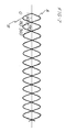
- the frequency waves produced by oscillation of the lip portions 32, 34 and the vibration dampening are depicted graphically and shown superimposed in which the frequency graph of the lip portions is labeled A and the frequency graph of the vibration dampening means is labeled B. It can be seen that the two frequency waves are 180° out of phase with each other and have equal but opposite amplitude such that the net sum of the two frequency waves at any given point will be zero corresponding to the elimination of noise produced by the valve.
- the width of the ribs 52, 54 is small and preferably less than 1/5 the width of the lip portions 32, 34, as measured in a direction parallel to the slit 50, such that the ribs 52, 54 do not interfere with the flexibility of the lip portions 32, 34 along the length of the slit 50.
- the lip portions 32, 34 have a thickness which is less than half the width of the ribs 52, 54 such that the ribs 52, 54 form enlarged weighted elements on the lip portions 32, 34 for substantially lowering the frequency for the vibrational movement of the lip portions 32, 34.
- the ribs 52, 54 are specifically designed to be located on the central portion of the valve lip portions 32, 34 where the greatest opening and closing movement occurs during operation of the valve 10. Further, the weight of the ribs 52, 54 acts.to decrease 4 or dampen the natural frequency of the lip portions 32, 34 in addition to the natural frequency of vibration for the ribs 52, 54 being counter to the lip vibration to eliminate whistling sounds produced by oscillating movement of the lip portions 32, 34.
- Fig. 5 illustrates a further embodiment of the present invention in which elements similar to the previous embodiment are indicated with the same number primed.
- the valve 10' has the same base structure 12' as in the previous embodiment.
- the present embodiment differs from the previous embodiment in that the regulator portion 14' is provided with third and fourth ribs 68', 70' located adjacent to the first and second ribs 52', 54', respectively, and extending from the lip portions 32', 34'.
- the additional ribs 68', 70' may be used to create a preload on the lip portions 32' 34' to ensure that sealing takes place while creating a minimum of back pressure in forward flow conditions.
- the valve 10' shown in this embodiment may be used in combination with a housing (not shown) having walls for engaging the third and fourth ribs 68', 70' whereby the ribs 68', 70' and the lip portions 32', 34' will be biased inwardly toward each other.
- Fig. 6 illustrates a typical use of the valve as it is incorporated into a medical wound drainage system.
- the system includes a manual suction device 72 for drawing fluid from a patient's wound through a suction line 74. Fluid drawn into the suction device 72 is subsequently transferred to a disposable bag 76.
- the suction device 72 is squeezed and then released causing fluid from a wound to be pulled through the line 74 and past a first one-way duckbill valve 10 and connected to the line 74 and attached to the suction device 72.
- fluid within the device 72 is pushed through a second one-way duckbill valve 10 attached to a lower end of the device 72 such that the fluid is transferred into the bag 76.
- the duckbill valve 10, 10'' of the present invention substantially eliminates any whistling noise produced during passage of the fluid, which may be in the form of liquids and air, from the suction device 72 to the bag 76 while providing a check valve which exhibits the beneficial characteristics of conventional duckbill check valves, including opening at low pressures and providing low restriction to forward flow, as well as providing quick and positive closure during reverse flow conditions.
Landscapes
- Engineering & Computer Science (AREA)
- General Engineering & Computer Science (AREA)
- Mechanical Engineering (AREA)
- Check Valves (AREA)
- Details Of Valves (AREA)
Abstract
Description
- The present invention relates to a duckbill check valve for use in a flow path for permitting relatively free flow of fluid in the flow path in a first direction from a first to a second end of the check valve and for preventing fluid flow in the path in a second opposite direction. More particularly, the present invention relates to a duckbill check valve having a construction which limits the vibration of lips forming the valve in order to prevent the production of whistling sounds during fluid flow through the valve.
- Duckbill valves are widely used to control fluid flow in a variety of devices. The structure of duckbill valves typically includes a pair of substantially planar lip portions which converge toward each other from a first to a second end of the valve. The lip portions are joined at lateral edges thereof by side walls such that the lip portions and side walls define a fluid flow path therethrough. The valve is typically formed of an elastomeric material and the lip portions are formed as thin highly flexible members which provide a low resistance to forward flow through the valve while producing a positive closing force for closing a slit at the second end of the valve to prevent reverse flow through the valve.
- Due to the highly flexible structure of the lip portions, fluid flow through the valve at certain pressures and fluid flow rates results in the lip portions flexing in and out at a high rate to produce a vibration resulting in a high pitch tone or whistling noise. This noise is undesirable in many applications of the valve. For example, duckbill valves are frequently used to control fluid flow in fluid lines used in medical environments where it is undesirable to have fluid flow noise, and this problem is particularly evident when the valve operates to control flow of a gas therethrough.
- Accordingly, there is a need for a valve which controls fluid flow in a desired direction and which does so without producing undesirable noise. In addition, there is a need for a valve which includes means for controlling noise related to vibrations of resilient portions of the valve in order to avoid production of noise during use of the valve.
- The present invention provides an anti-whistling duckbill check valve for use in a fluid flow path for permitting relatively free flow of fluid in the path in a first direction from a first to a second end of the valve and for preventing fluid flow in the path in a second opposite direction.
- In one aspect, the valve comprises a resilient valve body for controlling fluid flow, and a vibration dampener supported on the valve body for dampening a vibrating movement of the valve body during fluid flow past the valve.
- In another aspect, the check valve includes a base portion defining a longitudinal axis for the valve. First and second lip portions are supported by the base portion and extend in converging relationship toward each other to form a fluid flow passage through the valve. A slit is defined at the second end of the valve to form an opening for permitting fluid flow out of the flow passage.
- Vibration dampening means are located on each of the lip portions spaced from lateral edges thereof. The vibration dampening means may be in the form of ribs extending longitudinally along the lip portions wherein the depth of the ribs, as measured in a direction perpendicular to the slit, decreases at a substantially constant rate from the second end toward the first end of the valve.
- The vibration dampening elements increase the mass of the lip portions to substantially alter the vibration characteristics thereof. In addition, the vibration dampening elements form vibrating members having a natural frequency substantially equal to and out of phase with the lip portions such that audible noise producing vibrations of the lip portions are cancelled out by vibrations of the dampening means.
- Further, the vibration dampening elements control the movement of the lip portions without adversely affecting the beneficial characteristics of the duckbill valve including the ability to quickly open at low pressures, as well as provide a positive closure of the slit during reverse flow conditions.
- Various embodiments of the invention will now be described with reference to the accompanying drawings, in which:-
- Fig. 1 is a perspective view of the duckbill valve of the present invention;
- Fig. 2 is an elevational cross-sectional view taken along
line 2--2 in Fig. 1; - Fig. 3 is an elevational cross-sectional view taken along
line 3--3 in Fig. 1; - Fig. 4 is a plan view taken from the outlet end of the valve;
- Fig. 5 shows an alternative embodiment of the valve of the present invention;
- Fig. 6 is a view of the valve of the present invention in use in a medical fluid drainage system shown in cross-section; and
- Fig. 7 is a graphical representation of the frequency of oscillating movement for the lip portions and vibration dampening means of the valve.
- Referring to Fig. 1, the anti-whistling
duckbill check valve 10 of the present invention is shown and includes abase portion 12 and aregulator portion 14. Thebase portion 12 is adapted to support thevalve 10 in a fluid flow line and further provides a support structure for supporting theregulator portion 14. - Referring to Figs. 2 and 3, the base portion is defined by inner and
outer wall portions wall portion first end 20 toward asecond end 22 of thevalve 10. In addition, theinner wall 16 is provided with a substantiallycylindrical portion 24 which may facilitate attachment of thevalve 10 to a fluid flow line, and theouter wall 18 is provided with a substantiallycylindrical portion 26 which may facilitate mounting the outer portion of thevalve 10 to an interior wall of a fluid flow line wherein adjacenttapered portions walls cylindrical portions - A
flange 28 extends radially outwardly from thebase portion 12 at thefirst end 20 of the valve for further facilitating mounting of the valve to a fluid line or support surface. Theflange 28 is formed as an annular member and defines, along with the other base portion structure, a centrallongitudinal axis 30 for thevalve 10. - Referring to Figs. 2-4, the
regulator portion 14 includes first andsecond lip portions lip portions inner walls outer walls lip portions - The
lip portions curved side walls lip portions lip portions side walls fluid flow passage 48 through thevalve 10. Aslit 50 is formed between thelip portions second end 22 and provides an opening for permitting fluid flow out of theflow passage 48. - In the embodiment shown, the
lip portions outer walls slit 50. Further, thelip portions side walls base portion 12 is formed of an elastomeric material such that thelip portions slit 50 for forward flow of fluids through theflow passage 48 in a direction from thefirst end 20 to thesecond end 22 of thevalve 10. Theresilient lip portions slit 50 during reverse flow conditions. - As was noted above, the highly flexible nature of the lip portions of duckbill valves contributes to the vibration of the lip portions at a natural frequency during certain fluid flow conditions leading to the production of a whistling noise. In order to dampen and/or eliminate this vibration of the
lip portions second ribs base portion 12, toward a downstream location adjacent to thesecond end 22 of thevalve 10. - As may be best seen in Figs. 1, 2 and 4, each of the
ribs lateral walls walls ribs inner wall outer walls ribs lip portions ribs lip portions lip portions - The particular natural frequency selected for the
ribs ribs ribs lip portions ribs respective lip portions ribs - By selecting the values M, S and L such that the relationship between these parameters corresponds to the natural frequency of the
lip portions ribs lip portions ribs ribs lip portions lip portions ribs - It should be noted that although the vibration dampening means are disclosed here in the form of
ribs valve 10 in the audible range. - Further, referring to Fig. 7, the frequency waves produced by oscillation of the
lip portions - Referring again to Figs. 2 and 4, the width of the
ribs slit 50 between respectivelateral walls lip portions slit 50, such that theribs lip portions slit 50. It should also be noted that thelip portions ribs ribs lip portions lip portions - From the above description of the anti-whistling duckbill valve of the present invention, it should be apparent that the
ribs valve lip portions valve 10. Further, the weight of theribs lip portions ribs lip portions lip portions second end 22 of thelip portions slit 50, the dampening means operate without detrimentally affecting the flexibility of thelip portions slit 50 to permit forward fluid flow through thevalve 10. - Fig. 5 illustrates a further embodiment of the present invention in which elements similar to the previous embodiment are indicated with the same number primed. The valve 10' has the same base structure 12' as in the previous embodiment. The present embodiment differs from the previous embodiment in that the regulator portion 14' is provided with third and fourth ribs 68', 70' located adjacent to the first and second ribs 52', 54', respectively, and extending from the lip portions 32', 34'.
- The additional ribs 68', 70' may be used to create a preload on the lip portions 32' 34' to ensure that sealing takes place while creating a minimum of back pressure in forward flow conditions. The valve 10' shown in this embodiment may be used in combination with a housing (not shown) having walls for engaging the third and fourth ribs 68', 70' whereby the ribs 68', 70' and the lip portions 32', 34' will be biased inwardly toward each other.
- Fig. 6 illustrates a typical use of the valve as it is incorporated into a medical wound drainage system. The system includes a
manual suction device 72 for drawing fluid from a patient's wound through asuction line 74. Fluid drawn into thesuction device 72 is subsequently transferred to a disposable bag 76. - During operation, the
suction device 72 is squeezed and then released causing fluid from a wound to be pulled through theline 74 and past a first one-way duckbill valve 10 and connected to theline 74 and attached to thesuction device 72. When thesuction device 72 is subsequently squeezed, fluid within thedevice 72 is pushed through a second one-way duckbill valve 10 attached to a lower end of thedevice 72 such that the fluid is transferred into the bag 76. Theduckbill valve 10, 10'' of the present invention substantially eliminates any whistling noise produced during passage of the fluid, which may be in the form of liquids and air, from thesuction device 72 to the bag 76 while providing a check valve which exhibits the beneficial characteristics of conventional duckbill check valves, including opening at low pressures and providing low restriction to forward flow, as well as providing quick and positive closure during reverse flow conditions. - While the forms of apparatus herein described constitute preferred embodiments of the invention, it is to be understood that the invention is not limited to these precise forms of apparatus, and that changes may be made therein without departing from the scope of the invention which is defined in the appended claims.
Claims (20)
- A valve comprising:
a resilient valve body for controlling fluid flow; and
a vibration dampener supported on said valve body for dampening a vibrating movement of said valve body during fluid flow past said valve. - The valve of claim 1 wherein said valve body defines a first natural frequency and said vibration dampener defines a second natural frequency related to said first natural frequency.
- The valve of claim 1 wherein fluid flow through said valve causes said vibration dampener to vibrate at a natural frequency substantially equal to a frequency of vibration of said valve body created by said fluid flow.
- The valve of claim 3 wherein said vibration dampener vibrates out of phase with the vibration of said valve body whereby the vibrations of said valve body are cancelled by the vibrations of said vibration dampener.
- The valve of claim 1 wherein said vibration dampener is formed as a resilient cantilever member extending in spaced relation to said valve body.
- The valve of claim 5 wherein said resilient cantilever member has a natural frequency in accordance with a mathematical relationship containing M, L and S wherein M is the mass, S is the bending stiffness of the connection of said cantilever member with said valve body and L is the length of said cantilever member.
- The valve of claim 6 wherein said cantilever member has a natural frequency substantially equal to a natural frequency of said valve body.
- The valve of claim 1 wherein said valve body includes a base and opposing lips supported by said base and extending in converging relationship toward each other.
- The valve of claim 8 wherein said vibration dampener comprises a rib formed on an exterior surface of each of said lips, each said rib being configured to vibrate at a natural frequency cancelling vibrations of said lips.
- The valve of claim 9 wherein said opposing lips define a slit therebetween at one end of said valve and said ribs extend in spaced relation to said lips toward said one end of said valve.
- A method of controlling noise in a valve having a resilient valve body, comprising the steps of:
supporting a vibration dampener on said valve body for dampening movement of said valve body; and
causing a fluid to flow past said valve body to create a vibrating movement in each of said valve body and said vibration dampener wherein said vibration dampener vibrates out of phase with said valve body. - The method of claim 11 wherein said vibration dampener vibrates at a predetermined natural frequency regulated by the size, stiffness and mass of said vibration dampener, and said natural frequency is substantially equal and opposite to a natural frequency of said valve body.
- The method of claim 11 wherein said vibration dampener is mounted to move in response to vibrations of said valve body whereby said vibration dampener is caused to vibrate opposite to said valve body to control noise produced by said vibrations of said valve body.
- An anti-whistling duckbill check valve for use in a fluid flow path for permitting relatively free fluid flow in a first direction from a first end to a second end of said valve and for preventing fluid flow in a second opposite direction, said valve comprising:
a base portion defining a longitudinal axis for said valve;
first and second lip portions supported by said base portion and extending in converging relationship toward each other, said lip portions forming a fluid flow passage through said valve;
means defining a slit at said second end of said valve and forming an opening for fluid flow out of said flow passage; and
vibration dampeners located on said lip portions, said vibration dampeners extending from a location in contact with said lip portions at an upstream end of said vibration dampeners to a location in spaced relation to said lip portions at a downstream end of said vibration dampeners. - The valve of claim 14 wherein said vibration dampeners are formed as first and second ribs extending radially outwardly from outer walls of said first and second lip portions.
- The valve of claim 15 wherein said ribs extend substantially parallel to said longitudinal axis.
- The valve of claim 16 including third and fourth elongated ribs extending radially outwardly from said first and second ribs, respectively.
- The valve of claim 14 wherein said vibration dampeners comprise resilient cantilever members extending in spaced relation to said lip portions.
- The valve of claim 18 wherein said cantilever members are mounted to move in response to vibrations of said lip portions whereby said vibration dampeners are caused to vibrate opposite to respective ones of said lip portions to control noise produced by said lip portions.
- The valve of claim 14 wherein said vibration dampeners are configured to vibrate at a natural frequency substantially equal to and 180 degrees out of phase with a natural frequency of said lip portions to cancel out vibrations of said lip portions.
Applications Claiming Priority (2)
| Application Number | Priority Date | Filing Date | Title |
|---|---|---|---|
| US08/044,697 US5301707A (en) | 1993-04-12 | 1993-04-12 | Anti-whistling duckbill valve |
| US44697 | 1997-04-24 |
Publications (2)
| Publication Number | Publication Date |
|---|---|
| EP0624744A1 true EP0624744A1 (en) | 1994-11-17 |
| EP0624744B1 EP0624744B1 (en) | 1998-07-08 |
Family
ID=21933829
Family Applications (1)
| Application Number | Title | Priority Date | Filing Date |
|---|---|---|---|
| EP94302469A Expired - Lifetime EP0624744B1 (en) | 1993-04-12 | 1994-04-07 | Vibration dampered duckbill valve |
Country Status (3)
| Country | Link |
|---|---|
| US (1) | US5301707A (en) |
| EP (1) | EP0624744B1 (en) |
| DE (1) | DE69411453T2 (en) |
Cited By (2)
| Publication number | Priority date | Publication date | Assignee | Title |
|---|---|---|---|---|
| US7077296B2 (en) | 1991-12-06 | 2006-07-18 | Aptargroup, Inc. | Dispensing valve |
| WO2020125831A1 (en) | 2018-12-21 | 2020-06-25 | Aventics Gmbh | Sealing diaphragm and check valve having a sealing diaphragm for fluid technology applications |
Families Citing this family (42)
| Publication number | Priority date | Publication date | Assignee | Title |
|---|---|---|---|---|
| US5470319A (en) | 1994-06-20 | 1995-11-28 | Critical Device Corporation | Needleless injection site |
| US5957898A (en) | 1997-05-20 | 1999-09-28 | Baxter International Inc. | Needleless connector |
| AU732833B2 (en) | 1997-05-20 | 2001-05-03 | Baxter International Inc. | Needleless connector |
| DE19806101C2 (en) * | 1998-02-14 | 2001-05-10 | Diehl Stiftung & Co | Pressure equalization for buoyancy bags in the water |
| US6183461B1 (en) | 1998-03-11 | 2001-02-06 | Situs Corporation | Method for delivering a medication |
| US6062436A (en) | 1998-04-02 | 2000-05-16 | Owens-Illinois Closure Inc. | Flexible vented self-sealing dispensing valve |
| DE29907933U1 (en) | 1999-05-04 | 1999-08-12 | Georg Menshen GmbH & Co KG, 57413 Finnentrop | Slit closing valve for container openings |
| DE19925324C1 (en) * | 1999-06-02 | 2001-01-25 | Winter & Ibe Olympus | Trocar sleeve with duckbill valve |
| US6776421B2 (en) * | 2000-02-10 | 2004-08-17 | Delphi Technologies, Inc. | Fluid sealing system |
| JP2002349348A (en) | 2001-05-18 | 2002-12-04 | Walbro Japan Inc | Accelerating pump of float type carburetor |
| US7037303B2 (en) | 2001-07-06 | 2006-05-02 | Opticon Medical, Inc. | Urinary flow control valve |
| US6533254B1 (en) | 2001-10-05 | 2003-03-18 | Walbro Corporation | Carburetor fuel pump |
| US6702255B2 (en) * | 2001-11-08 | 2004-03-09 | Edwards Lifesciences Corporation | H-shape duckbill hemostasis valve assembly including guide wire seal |
| US6908459B2 (en) | 2001-12-07 | 2005-06-21 | Becton, Dickinson And Company | Needleless luer access connector |
| ATE385826T1 (en) * | 2002-08-12 | 2008-03-15 | Jms Co Ltd | NEEDLELESS OPENING AND PRODUCTION PROCESS THEREOF |
| EP1579133B1 (en) * | 2002-12-23 | 2011-03-30 | Peter Kasper Dahm | Fluid control valve |
| JP4413660B2 (en) * | 2004-03-15 | 2010-02-10 | 日本トムソン株式会社 | Oiling plug and stud type track roller with oiling plug |
| ES2547723T3 (en) * | 2004-10-14 | 2015-10-08 | Sumitomo Bakelite Company, Limited | Treatment instrument for aortocoronary bypass surgery |
| USD548343S1 (en) | 2005-10-26 | 2007-08-07 | Smiths Medical Asd, Inc. | Valve element portion for momentary high pressure valve |
| US7302960B2 (en) * | 2005-10-26 | 2007-12-04 | Smiths Medical Asd, Inc. | Momentary high pressure valve |
| CN103203054B (en) | 2005-12-02 | 2016-08-03 | C.R.巴德有限公司 | Pressure-activated proximal valves |
| US20070244426A1 (en) * | 2006-04-13 | 2007-10-18 | Applied Medical Resources Corporation | Duck bill septum combination |
| US7854562B2 (en) * | 2006-06-20 | 2010-12-21 | Wagner Spray Tech Corporation | Internal feed manual paint brush |
| USD576800S1 (en) | 2006-06-20 | 2008-09-16 | Wagner Spray Tech Corporation | Paint brush with asymmetric handle |
| JP5136873B2 (en) * | 2006-07-14 | 2013-02-06 | 隆 片山 | Container with liquid extraction nozzle |
| US8561851B1 (en) * | 2007-03-23 | 2013-10-22 | Christopher A. Leonoff | Sports bottle with preloaded valve and methods |
| US7857883B2 (en) | 2007-10-17 | 2010-12-28 | Cummins Filtration Ip, Inc. | Inertial gas-liquid separator with constrictable and expansible nozzle valve sidewall |
| GB0916318D0 (en) * | 2009-09-17 | 2009-10-28 | Samson Ilan Z | Spout for a spill-proof beverage container |
| US9139991B2 (en) | 2011-01-31 | 2015-09-22 | The Rectorseal Corporation | Floor drain valve with resiliently mounted rigid flappers |
| US10337194B2 (en) | 2011-06-29 | 2019-07-02 | Safeway Services, Llc | Work platform system configured for use structure with internal cavity, and related methods of assembly and use |
| WO2013082613A1 (en) * | 2011-12-01 | 2013-06-06 | Munchkin, Inc. | System and method for venting, priming and modifying a flow rate of fluid from a container |
| US9347574B1 (en) | 2012-04-04 | 2016-05-24 | Taylo Innovations LLC | Self actuating weather protective cover |
| US20140252042A1 (en) * | 2013-03-06 | 2014-09-11 | Georgia-Pacific Consumer Products Lp | Fluid dispenser |
| US9416986B2 (en) | 2013-06-24 | 2016-08-16 | The Rectorseal Corporation | Valve for roof vent |
| US9010363B2 (en) | 2013-06-24 | 2015-04-21 | The Rectorseal Corporation | Drain valve |
| WO2015197599A1 (en) * | 2014-06-23 | 2015-12-30 | Pernod Ricard Sa | Duckbill valve arrangement for a beverage dispensing container |
| US9822885B2 (en) | 2014-08-29 | 2017-11-21 | Automatic Switch Company | Flow rib in valves |
| AU2017300752B2 (en) * | 2016-07-21 | 2022-02-24 | Red Valve Company, Inc. | Elastomeric in-line tide gate valve |
| WO2018191540A1 (en) * | 2017-04-12 | 2018-10-18 | Clifford Jeffrey | Liquid container having integrated auxiliary flask |
| US11662034B2 (en) * | 2019-07-24 | 2023-05-30 | Quest Medical, Inc. | Filtered vacuum relief vent valve |
| US11577011B2 (en) * | 2020-04-30 | 2023-02-14 | Robert Harder | Chest valve for treating pneumothorax |
| CN115899332A (en) * | 2022-11-17 | 2023-04-04 | 中霖中科环境科技(安徽)股份有限公司 | Multi outlet duckbill valve |
Citations (3)
| Publication number | Priority date | Publication date | Assignee | Title |
|---|---|---|---|---|
| US3736953A (en) * | 1971-11-30 | 1973-06-05 | Sarns Inc | Low pressure check valve |
| EP0452045A1 (en) * | 1990-04-09 | 1991-10-16 | Vernay Laboratories, Inc. | Normally closed duckbill valve assembly |
| US5261459A (en) * | 1992-12-07 | 1993-11-16 | Vernay Laboratories, Inc. | Miniature duckbill valve having a low cracking pressure and high flow rate |
Family Cites Families (4)
| Publication number | Priority date | Publication date | Assignee | Title |
|---|---|---|---|---|
| US3822720A (en) * | 1971-03-04 | 1974-07-09 | Noyce R | Flow control assembly |
| US3896849A (en) * | 1972-02-13 | 1975-07-29 | Ford Motor Co | Pressure relief valve |
| US4341239A (en) * | 1980-07-14 | 1982-07-27 | Vernay Laboratories, Inc. | Combination check-overpressure relief valve |
| US4612960A (en) * | 1985-02-21 | 1986-09-23 | Vernay Laboratories, Inc. | Valve assembly |
-
1993
- 1993-04-12 US US08/044,697 patent/US5301707A/en not_active Expired - Lifetime
-
1994
- 1994-04-07 DE DE69411453T patent/DE69411453T2/en not_active Expired - Lifetime
- 1994-04-07 EP EP94302469A patent/EP0624744B1/en not_active Expired - Lifetime
Patent Citations (3)
| Publication number | Priority date | Publication date | Assignee | Title |
|---|---|---|---|---|
| US3736953A (en) * | 1971-11-30 | 1973-06-05 | Sarns Inc | Low pressure check valve |
| EP0452045A1 (en) * | 1990-04-09 | 1991-10-16 | Vernay Laboratories, Inc. | Normally closed duckbill valve assembly |
| US5261459A (en) * | 1992-12-07 | 1993-11-16 | Vernay Laboratories, Inc. | Miniature duckbill valve having a low cracking pressure and high flow rate |
Cited By (3)
| Publication number | Priority date | Publication date | Assignee | Title |
|---|---|---|---|---|
| US7077296B2 (en) | 1991-12-06 | 2006-07-18 | Aptargroup, Inc. | Dispensing valve |
| WO2020125831A1 (en) | 2018-12-21 | 2020-06-25 | Aventics Gmbh | Sealing diaphragm and check valve having a sealing diaphragm for fluid technology applications |
| DE102018009963A1 (en) | 2018-12-21 | 2020-06-25 | Aventics Gmbh | Sealing membrane and check valve with sealing membrane for fluid power applications |
Also Published As
| Publication number | Publication date |
|---|---|
| DE69411453T2 (en) | 1998-11-12 |
| US5301707A (en) | 1994-04-12 |
| EP0624744B1 (en) | 1998-07-08 |
| DE69411453D1 (en) | 1998-08-13 |
Similar Documents
| Publication | Publication Date | Title |
|---|---|---|
| US5301707A (en) | Anti-whistling duckbill valve | |
| US4947434A (en) | Electronic attenuator | |
| JP4993755B2 (en) | Intake sound generator | |
| US4671380A (en) | Hydraulic noise attenuators | |
| US8821134B2 (en) | Fluid disc pump | |
| US20050173852A1 (en) | Damper for hydraulic systems | |
| WO2013158659A1 (en) | Disc pump with perimeter valve configuration | |
| JP2016533996A (en) | Equipment for transferring powder | |
| US5101930A (en) | Hydraulic elevator muffler | |
| KR870007793A (en) | Mounting Block for Vibration | |
| JPH06323360A (en) | Vibration damping supporter | |
| EP1286077A3 (en) | Liquid-sealed vibration-proof device | |
| JP4661694B2 (en) | Intake sound increaser | |
| US7228846B2 (en) | Apparatus, system, and method for reducing pressure pulsations and attenuating noise transmission in a fuel system | |
| US20230404810A1 (en) | Acoustic Fluid and Earplug | |
| US4738435A (en) | Fluid filled vibration isolator which operates quietly over broad frequency and amplitude ranges | |
| CN103238006A (en) | Reduced noise decoupler | |
| WO2011003700A1 (en) | Check valve | |
| JP2006521965A (en) | Attenuation of fluid disturbances in fluid-driven actuators. | |
| CN107035580B (en) | Intake noise reduction device for internal combustion engine | |
| US8342902B2 (en) | Deer call | |
| JP2007107847A (en) | Throttle device and refrigerant piping | |
| JP2007321964A (en) | Vibration control device | |
| JP2003214482A (en) | Hanging liquid ring engine mount | |
| JPS633246B2 (en) |
Legal Events
| Date | Code | Title | Description |
|---|---|---|---|
| PUAI | Public reference made under article 153(3) epc to a published international application that has entered the european phase |
Free format text: ORIGINAL CODE: 0009012 |
|
| AK | Designated contracting states |
Kind code of ref document: A1 Designated state(s): DE FR GB IT |
|
| 17P | Request for examination filed |
Effective date: 19950322 |
|
| 17Q | First examination report despatched |
Effective date: 19961010 |
|
| GRAG | Despatch of communication of intention to grant |
Free format text: ORIGINAL CODE: EPIDOS AGRA |
|
| GRAG | Despatch of communication of intention to grant |
Free format text: ORIGINAL CODE: EPIDOS AGRA |
|
| GRAH | Despatch of communication of intention to grant a patent |
Free format text: ORIGINAL CODE: EPIDOS IGRA |
|
| GRAH | Despatch of communication of intention to grant a patent |
Free format text: ORIGINAL CODE: EPIDOS IGRA |
|
| GRAA | (expected) grant |
Free format text: ORIGINAL CODE: 0009210 |
|
| AK | Designated contracting states |
Kind code of ref document: B1 Designated state(s): DE FR GB IT |
|
| REF | Corresponds to: |
Ref document number: 69411453 Country of ref document: DE Date of ref document: 19980813 |
|
| ET | Fr: translation filed | ||
| PLBE | No opposition filed within time limit |
Free format text: ORIGINAL CODE: 0009261 |
|
| STAA | Information on the status of an ep patent application or granted ep patent |
Free format text: STATUS: NO OPPOSITION FILED WITHIN TIME LIMIT |
|
| 26N | No opposition filed | ||
| REG | Reference to a national code |
Ref country code: GB Ref legal event code: IF02 |
|
| PGFP | Annual fee paid to national office [announced via postgrant information from national office to epo] |
Ref country code: DE Payment date: 20130419 Year of fee payment: 20 Ref country code: GB Payment date: 20130418 Year of fee payment: 20 |
|
| PGFP | Annual fee paid to national office [announced via postgrant information from national office to epo] |
Ref country code: FR Payment date: 20130515 Year of fee payment: 20 Ref country code: IT Payment date: 20130424 Year of fee payment: 20 |
|
| REG | Reference to a national code |
Ref country code: DE Ref legal event code: R071 Ref document number: 69411453 Country of ref document: DE |
|
| REG | Reference to a national code |
Ref country code: GB Ref legal event code: PE20 Expiry date: 20140406 |
|
| PG25 | Lapsed in a contracting state [announced via postgrant information from national office to epo] |
Ref country code: GB Free format text: LAPSE BECAUSE OF EXPIRATION OF PROTECTION Effective date: 20140406 |
|
| PG25 | Lapsed in a contracting state [announced via postgrant information from national office to epo] |
Ref country code: DE Free format text: LAPSE BECAUSE OF EXPIRATION OF PROTECTION Effective date: 20140408 |