EP0624740B1 - Compound transmission having hybrid single and twin countershafts - Google Patents
Compound transmission having hybrid single and twin countershafts Download PDFInfo
- Publication number
- EP0624740B1 EP0624740B1 EP94303338A EP94303338A EP0624740B1 EP 0624740 B1 EP0624740 B1 EP 0624740B1 EP 94303338 A EP94303338 A EP 94303338A EP 94303338 A EP94303338 A EP 94303338A EP 0624740 B1 EP0624740 B1 EP 0624740B1
- Authority
- EP
- European Patent Office
- Prior art keywords
- countershaft
- gear
- gears
- shaft
- clutch
- Prior art date
- Legal status (The legal status is an assumption and is not a legal conclusion. Google has not performed a legal analysis and makes no representation as to the accuracy of the status listed.)
- Expired - Lifetime
Links
- 230000005540 biological transmission Effects 0.000 title claims abstract description 82
- 150000001875 compounds Chemical class 0.000 title claims abstract description 46
- 230000008878 coupling Effects 0.000 claims description 17
- 238000010168 coupling process Methods 0.000 claims description 17
- 238000005859 coupling reaction Methods 0.000 claims description 17
- 230000008859 change Effects 0.000 description 5
- 230000009467 reduction Effects 0.000 description 3
- 230000007935 neutral effect Effects 0.000 description 2
- 238000010276 construction Methods 0.000 description 1
- 230000009977 dual effect Effects 0.000 description 1
- 239000012530 fluid Substances 0.000 description 1
- 230000008676 import Effects 0.000 description 1
- 238000004513 sizing Methods 0.000 description 1
- 238000010396 two-hybrid screening Methods 0.000 description 1
Images

Classifications
-
- F—MECHANICAL ENGINEERING; LIGHTING; HEATING; WEAPONS; BLASTING
- F16—ENGINEERING ELEMENTS AND UNITS; GENERAL MEASURES FOR PRODUCING AND MAINTAINING EFFECTIVE FUNCTIONING OF MACHINES OR INSTALLATIONS; THERMAL INSULATION IN GENERAL
- F16H—GEARING
- F16H3/00—Toothed gearings for conveying rotary motion with variable gear ratio or for reversing rotary motion
- F16H3/02—Toothed gearings for conveying rotary motion with variable gear ratio or for reversing rotary motion without gears having orbital motion
- F16H3/08—Toothed gearings for conveying rotary motion with variable gear ratio or for reversing rotary motion without gears having orbital motion exclusively or essentially with continuously meshing gears, that can be disengaged from their shafts
- F16H3/087—Toothed gearings for conveying rotary motion with variable gear ratio or for reversing rotary motion without gears having orbital motion exclusively or essentially with continuously meshing gears, that can be disengaged from their shafts characterised by the disposition of the gears
- F16H3/093—Toothed gearings for conveying rotary motion with variable gear ratio or for reversing rotary motion without gears having orbital motion exclusively or essentially with continuously meshing gears, that can be disengaged from their shafts characterised by the disposition of the gears with two or more countershafts
- F16H3/095—Toothed gearings for conveying rotary motion with variable gear ratio or for reversing rotary motion without gears having orbital motion exclusively or essentially with continuously meshing gears, that can be disengaged from their shafts characterised by the disposition of the gears with two or more countershafts with means for ensuring an even distribution of torque between the countershafts
-
- F—MECHANICAL ENGINEERING; LIGHTING; HEATING; WEAPONS; BLASTING
- F16—ENGINEERING ELEMENTS AND UNITS; GENERAL MEASURES FOR PRODUCING AND MAINTAINING EFFECTIVE FUNCTIONING OF MACHINES OR INSTALLATIONS; THERMAL INSULATION IN GENERAL
- F16H—GEARING
- F16H37/00—Combinations of mechanical gearings, not provided for in groups F16H1/00 - F16H35/00
- F16H37/02—Combinations of mechanical gearings, not provided for in groups F16H1/00 - F16H35/00 comprising essentially only toothed or friction gearings
- F16H37/04—Combinations of toothed gearings only
- F16H37/042—Combinations of toothed gearings only change gear transmissions in group arrangement
- F16H37/043—Combinations of toothed gearings only change gear transmissions in group arrangement without gears having orbital motion
-
- F—MECHANICAL ENGINEERING; LIGHTING; HEATING; WEAPONS; BLASTING
- F16—ENGINEERING ELEMENTS AND UNITS; GENERAL MEASURES FOR PRODUCING AND MAINTAINING EFFECTIVE FUNCTIONING OF MACHINES OR INSTALLATIONS; THERMAL INSULATION IN GENERAL
- F16H—GEARING
- F16H2200/00—Transmissions for multiple ratios
- F16H2200/003—Transmissions for multiple ratios characterised by the number of forward speeds
- F16H2200/0065—Transmissions for multiple ratios characterised by the number of forward speeds the gear ratios comprising nine forward speeds
-
- F—MECHANICAL ENGINEERING; LIGHTING; HEATING; WEAPONS; BLASTING
- F16—ENGINEERING ELEMENTS AND UNITS; GENERAL MEASURES FOR PRODUCING AND MAINTAINING EFFECTIVE FUNCTIONING OF MACHINES OR INSTALLATIONS; THERMAL INSULATION IN GENERAL
- F16H—GEARING
- F16H2200/00—Transmissions for multiple ratios
- F16H2200/0082—Transmissions for multiple ratios characterised by the number of reverse speeds
- F16H2200/0086—Transmissions for multiple ratios characterised by the number of reverse speeds the gear ratios comprising two reverse speeds
-
- F—MECHANICAL ENGINEERING; LIGHTING; HEATING; WEAPONS; BLASTING
- F16—ENGINEERING ELEMENTS AND UNITS; GENERAL MEASURES FOR PRODUCING AND MAINTAINING EFFECTIVE FUNCTIONING OF MACHINES OR INSTALLATIONS; THERMAL INSULATION IN GENERAL
- F16H—GEARING
- F16H3/00—Toothed gearings for conveying rotary motion with variable gear ratio or for reversing rotary motion
- F16H3/02—Toothed gearings for conveying rotary motion with variable gear ratio or for reversing rotary motion without gears having orbital motion
- F16H3/08—Toothed gearings for conveying rotary motion with variable gear ratio or for reversing rotary motion without gears having orbital motion exclusively or essentially with continuously meshing gears, that can be disengaged from their shafts
- F16H3/087—Toothed gearings for conveying rotary motion with variable gear ratio or for reversing rotary motion without gears having orbital motion exclusively or essentially with continuously meshing gears, that can be disengaged from their shafts characterised by the disposition of the gears
- F16H3/093—Toothed gearings for conveying rotary motion with variable gear ratio or for reversing rotary motion without gears having orbital motion exclusively or essentially with continuously meshing gears, that can be disengaged from their shafts characterised by the disposition of the gears with two or more countershafts
- F16H3/097—Toothed gearings for conveying rotary motion with variable gear ratio or for reversing rotary motion without gears having orbital motion exclusively or essentially with continuously meshing gears, that can be disengaged from their shafts characterised by the disposition of the gears with two or more countershafts the input and output shafts being aligned on the same axis
-
- Y—GENERAL TAGGING OF NEW TECHNOLOGICAL DEVELOPMENTS; GENERAL TAGGING OF CROSS-SECTIONAL TECHNOLOGIES SPANNING OVER SEVERAL SECTIONS OF THE IPC; TECHNICAL SUBJECTS COVERED BY FORMER USPC CROSS-REFERENCE ART COLLECTIONS [XRACs] AND DIGESTS
- Y10—TECHNICAL SUBJECTS COVERED BY FORMER USPC
- Y10T—TECHNICAL SUBJECTS COVERED BY FORMER US CLASSIFICATION
- Y10T74/00—Machine element or mechanism
- Y10T74/19—Gearing
- Y10T74/19167—In series plural interchangeably locked nonplanetary units
-
- Y—GENERAL TAGGING OF NEW TECHNOLOGICAL DEVELOPMENTS; GENERAL TAGGING OF CROSS-SECTIONAL TECHNOLOGIES SPANNING OVER SEVERAL SECTIONS OF THE IPC; TECHNICAL SUBJECTS COVERED BY FORMER USPC CROSS-REFERENCE ART COLLECTIONS [XRACs] AND DIGESTS
- Y10—TECHNICAL SUBJECTS COVERED BY FORMER USPC
- Y10T—TECHNICAL SUBJECTS COVERED BY FORMER US CLASSIFICATION
- Y10T74/00—Machine element or mechanism
- Y10T74/19—Gearing
- Y10T74/19219—Interchangeably locked
- Y10T74/19233—Plurality of counter shafts
Definitions
- the present invention relates to compound transmissions including a multispeed main transmission section connected in series with a multispeed auxiliary transmission section, and in particular to such a compound transmission having clutches situated on two hybrid main section countershafts for selecting main section gears.
- Compound change gear transmissions of the type having one or more auxiliary sections connected in series with a main transmission section are known in the prior art. Briefly, by utilizing main and auxiliary transmission sections connected in series, assuming proper sizing of the ratio steps, the total of available transmission ratios is equal to the product of the main and auxiliary section ratios.
- Auxiliary transmission sections are of three general types: range type, splitter type or combined range/splitter type.
- range type auxiliary section the ratio step or steps are greater than the total ratio coverage of the main transmission section and the main section is shifted progressively through its ratios in each range.
- Examples of compound transmissions having range type auxiliary sections may be seen by reference to U.S. Patent No. 3,105,395; U.S. Patent No. 2,637,222; and U.S. Patent No. 2,637,221.
- the ratio steps of the splitter auxiliary section are less than the ratio steps of the main transmission section and each main section ratio is split, or subdivided, by the splitter section.
- Examples of compound change gear transmissions having splitter type auxiliary sections may be seen by reference to U.S. Patent No. 4,290,515; U.S. Patent No. 3,799,002; U.S. Patent No. 4,440,037; and U.S. Patent No. 4,527,447.
- both range and splitter type ratios are provided allowing the main section to be progressively shifted through its ratios in at least two ranges and also allowing the main section ratios to be split in at least one range.
- Examples of a compound transmission having a single combined range/splitter type auxiliary section may be seen by reference to U.S. Patent No. 3,283,613 and U.S. Patent No. 3,648,546. Eaton also produces the "Super 10" compound transmission which has a 2+1 main section and an auxiliary section having both range and splitter gears. All three forward ratios are used in the low range, while two forward ratios are repeated in the high range. This results in a standard 5 speed shift pattern.
- GB-A-2067689 a transmission is shown although not of a compound construction.
- a pair of countershafts are shown and synchronizing 'clutches and couplings are shown mounted on both the main shaft and in pairs on the countershaft.
- Another example of a combined range and splitter type compound transmission is the "Ecosplit" model of transmission sold by Zahnradfabrik Friedrichshafen Aktiengesellschaft of Friedrichshafen, Germany, which utilizes a separate splitter auxiliary section in front of, and a separate range auxiliary section behind, the main transmission section.
- Still another example is the RMO-13-145A thirteen speed transmission sold by Rockwell Corporation, in which the high range forward ratios are split.
- main and auxiliary section are relative and that if the designations of the main and auxiliary sections are reversed, the type of auxiliary section (either range or splitter) will also be reversed. In other words, given what is conventionally considered a four-speed main section with two-speed range type auxiliary section, if the normally designated auxiliary is considered the main section, the normally designated main section would be considered a four-speed splitter type auxiliary section therefor.
- the main transmission section of a compound transmission is that section which contains the largest (or at least no less) number of forward speed ratios, which allows selection of a neutral position, which contains the reverse ratio(s) and/or which is shifted (in manual or semiautomatic transmissions) by manipulation of a shift bar or shift rail or shift shaft/shift finger assembly as opposed to master/slave valve/cylinder arrangements or the like.
- the present invention is a compound transmission described in claims 1 and 12, the embodiments of the transmission claimed in claim 1 comprising a main transmission section connected in series with an auxiliary transmission section.
- the main section includes a mainshaft and two countershafts.
- the mainshaft has a spool gear rotatably mounted thereon and reverse, first, second, third and fourth forward gears rotationally fixed thereto.
- the first countershaft has first and second countershaft gears rotatably mounted thereon and a third countershaft gear rotationally fixed thereto.
- the first, second and third countershaft gears rotatably engage the first forward gear, third forward gear, and spool gear, respectively.
- the second countershaft has fourth and fifth countershaft gears rotatably mounted thereon and a sixth countershaft gear rotationally fixed thereto.
- the fourth, fifth and sixth countershaft gears rotatably engage the second forward gear, fourth forward gear, and spool gear, respectively.
- a first clutch is splined on the first countershaft and couples either the first countershaft gear or the second countershaft gear to the first countershaft.
- a second clutch is splined on the second countershaft and couples either the fourth countershaft gear or the fifth countershaft gear to the second countershaft.
- the auxiliary section includes an output shaft and third countershaft.
- the output shaft has a splitter gear rotatably mounted thereon.
- the third countershaft is concentric with the first countershaft, and is rotatably driven by the spool gear.
- the third countershaft has seventh and eighth countershaft gears rotatable with the third countershaft and rotatably engaged with the fourth forward gear and the splitter gear, respectively.
- Claim 12 describes an arrangement in which the fourth countershaft is concentric with the second countershaft, and is rotatably driven by the spool gear.
- the fourth countershaft has ninth and tenth countershaft gears rotatable with the fourth countershaft and rotatably engaged with the fourth forward gear and the splitter gear, respectively.
- a third clutch is splined on the output shaft and couples either the fourth forward gear or the splitter gear to the output shaft.
- a fourth clutch is splined on the mainshaft and couples the mainshaft to either the spool gear or to the fourth forward gear.
- compound transmission is used to designate a change speed or change gear transmission having a multiple forward speed main transmission section and a multiple speed auxiliary transmission section connected in series whereby the selected gear reduction in the main transmission section may be compounded by further selected gear reduction in the auxiliary transmission section.
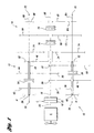
- FIGS 1 and 2 show a ten speed "5x2" compound transmission 10 according to the present invention.
- Compound transmission 10 comprises a multiple speed main transmission section 12 connected in series with an auxiliary transmission section 14.
- transmission 10 is housed within a single housing H and includes an input shaft 16 driven by a prime mover such as diesel engine E through a selectively disengaged, normally engaged friction master clutch C having an input or driving portion 18 drivingly connected to the engine crankshaft 20 and a driven portion 22 rotatably fixed to the transmission input shaft 16.
- a prime mover such as diesel engine E
- a selectively disengaged, normally engaged friction master clutch C having an input or driving portion 18 drivingly connected to the engine crankshaft 20 and a driven portion 22 rotatably fixed to the transmission input shaft 16.
- the input or mainshaft 16 has a compound or spool gear 24 rotatably mounted thereon and a plurality of drive gears 26, 28, 30 and 32 rotationally fixed thereto.
- a drive gear 60 is rotatably mounted on the end of the mainshaft 16.
- the drive gear 28 may be formed as an involute spline on the mainshaft 16, as shown in Figure 2, and may extend as an extenal spline along the mainshaft to drive the drive gears 26 and 30.
- Two substantially identical countershafts 34 and 36 are situated on opposite sides of the mainshaft 16, and are supported by bearings 38 and 40 in housing H, only a portion of which is schematically illustrated in Figure 1.
- the main section countershaft 34 is provided with main section countershaft gears 42 and 44 rotatably mounted thereon, and a countershaft gear 46 fixed for rotation therewith.
- the main section countershaft 36 is provided with main section countershaft gears 48 and 50 rotatably mounted thereon, and a countershaft gear 52 substantially identical to countershaft gear 46 fixed for rotation therewith.
- the mainshaft drive gear 32 is a reverse gear, and is rotatably engaged with the countershaft gear 50 mounted on the countershaft 36 through a conventional idler gear (not shown).
- the drive gear 28 provides a low or first forward speed ratio, and is rotatably engaged with the countershaft gear 48.
- the other two mainshaft drive gears 30 and 26 provide second and third forward speed ratios, and are respectively rotatably engaged with countershaft gears 44 and 42 mounted on the opposite countershaft 34.
- the countershaft gears 46 and 52 are rotatably engaged with the larger diameter portion of the spool gear 24.
- Clutch collars 54 and 56 are respectively splined on the countershafts 34 and 36 for rotation therewith, and are axially positionable to either a fully leftward or fully rightward location, or in a centered, nonengaged position.
- the clutch collars 54 and 56 are axially positioned by means of shift yokes or forks (not illustrated) associated with a shift bar housing assembly (not illustrated), for example as described in U.S. Patent No. 4,901,600, assigned to the assignee of the present invention.
- Clutch collars 54 and 56 are, in the preferred embodiment, of the well known nonsynchronized double acting jaw clutch type. As is well known, only one of the clutches 54 or 56 is engageable at a given time and main section interlock means are provided to lock the other clutch in the neutral condition.
- Auxiliary transmission section 14 is connected in series with main transmission section 12.
- An output shaft 58 generally coaxial with the mainshaft 16 carries the splitter gear 60 rotatably mounted thereon.
- the fourth forward gear 60 and the splitter gear 62 are respectively rotatably engaged with auxiliary section countershaft gear pairs 64 and 66, which in turn are rotationally fixed to auxiliary section countershafts 68 and 80.
- the auxiliary section countershafts 68 and 80 are supported by bearings 70 and 72 in housing H, and each auxiliary section countershaft also has an auxiliary section countershaft gear 74 fixed for rotation therewith.
- the gear 74 constantly meshes with the smaller diameter portion of the spool gear 24 so that the auxiliary countershafts 68 and 80 are rotatably drivable by the spool gear 24.
- Main transmission section 12 provides a reverse speed ratio and five selectable forward speed ratios.
- the reverse speed ratio is provided by positioning the clutch 56 to its fully rightward position to drivingly connect the countershaft gear 50 to the countershaft 36.
- the power path thus provided is from the mainshaft 16 through the reverse gear 32, the idler gear, and the countershaft gear 50 to the countershaft 36, and then through the countershaft gear 52 to the spool gear 24.
- the first and lowest forward speed ratio is provided by moving the clutch 56 to its fully leftward position to drivingly connect the countershaft gear 48 to the countershaft 36.
- the power path thus provided is from the mainshaft 16 through the drive gear 28 and the countershaft gear 48 to the countershaft 36, and then through the countershaft gear 52 to the spool gear 24.
- the second and third forward ratios are obtained by alternating the clutch 54 between it rightwardmost and leftwardmost positions to drivingly couple gears 44 or 42 to the countershaft 34.
- the power path provided by the former couple is from the mainshaft 16 through the drive gear 30 and the countershaft gear 44 to the countershaft 34, and then through the countershaft gear 46 to the spool gear 24.
- the power path provided by the latter couple is from the mainshaft 16 through the drive gear 26 and the countershaft gear 42 to the countershaft 34, and then through the countershaft gear 46 to the spool gear 24.
- a sliding three position jaw clutch collar 76 is splined on the end of the mainshaft 16 for rotation therewith.
- Clutch assembly 76 may be selectively located in the leftwardmost axial position to drivingly couple the spool gear 24 to the mainshaft 16 to provide a fourth forward speed ratio.
- Clutch assembly 76 may also be located in a centered nonengaged position, or in the rightwardmost axial position to drivingly couple the mainshaft to the drive gear 60 to provide a fifth forward speed ratio.
- clutch assembly 76 is shifted by a fork (not shown) controlled by the vehicle operator.
- a sliding two position jaw clutch collar 78 is similarly splined to and rotatable with the ouput shaft 58.
- Splitter clutch collar 78 may be selectively located in the leftwardmost axial position to drivingly couple the drive gear 60 to the output shaft 58, or may be selectively located in the rightwardmost axial position to rotationally couple the back splitter gear 62 to the output shaft.
- clutch assembly 78 is axially positioned by means of a shift fork (not shown) controlled by a remotely controlled fluid actuated piston assembly.
- the piston assembly is operable by a driver selection switch such as a button or the like on the shift knob, for example as described in U.S. Patent No. 5,000,060, assigned to the assignee of the present invention.
- the structure and function of the sliding jaw clutches 76 and 78 are substantially identical to the structure and function of jaw clutch collars 54 and 56 utilized in the main transmission section 12.
- Each of the five forward speed ratios, as well as the reverse speed ratio, are split in the auxiliary section 14 by moving the splitter clutch 78.
- the clutch 78 is moved to its fully leftward position to couple the drive gear 60 to the output shaft 58.
- the power path thus provided is from the spool gear 24 through the auxiliary countershaft drive gear 74 to the auxiliary countershaft 68, and then through the auxiliary countershaft gear 64 and the drive gear 60 to the output shaft 58.
- the splitter clutch 78 is shifted to its rightwardmost axial position to couple the back splitter gear 62 to the output shaft 58.
- the power path thus provided is from the spool gear 24 through the auxiliary countershaft drive gear 74 to the auxiliary countershaft 68, and then through the auxiliary countershaft gear 66 and the back splitter gear 62 to the output shaft 58.
- the ninth forward speed ratio is a direct drive, and is provided by moving the mainshaft clutch 76 to its fully rightward position to couple the mainshaft 16 to the drive gear 60, and simultaneously positioning the splitter clutch 78 to couple the drive gear 60 to the output shaft 58.
- the tenth forward speed ratio is an overdrive ratio, and is provided by maintaining the mainshaft clutch 76 in the fully rightward position to couple the mainshaft 16 to the drive gear 60, and moving the splitter clutch 78 to couple the back splitter gear 62 to the output shaft 58.
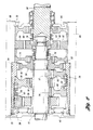
- FIG. 2 shows a preferred embodiment of the compound transmission 10 shown in Figure 1.
- a fourth countershaft 80 is provided having countershaft gears- 82 and 84 fixed for rotation therewith.
- the auxiliary countershaft 80 extends through the main section 12, where the main section countershaft 36 is in the form of a tube located concentrically around and rotatable with respect to the auxiliary section countershaft 80.
- the main section countershaft 34 is similarly in the form of a tube located concentrically around and rotatable with respect to an extension of the auxiliary section countershaft 68.
- the clutches 54 and 56 are therefore respectively splined to the tubes 34 and 36.
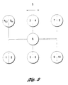
- Figure 3 shows the shift pattern for the ten speed compound transmission 10. Divisions in the horizontal direction represented by arrow S represent splitter shifts. All of the six shift pattern positions provide two selectable ratios, including the reverse gear position. In the leftwardmore shift pattern positions, the splitter clutch 78 couples the drive gear 60 to the output shaft 58. In the rightwardmore shift pattern positions, the clutch 78 couples the back splitter gear 62 to the output shaft 58. Because the reverse ratio and the five forward ratios can all be split in the auxiliary section, the shift pattern for the compound transmission 10 has a standard 5 speed, non-repeat shift pattern.
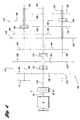
- Figures 4 and 5 show an alternative "2x5" embodiment 100 of the present invention with the main section 112 behind the auxiliary section 114.
- the input shaft 116 carries a splitter gear 160 rotatably mounted thereon, and a splitter clutch 178 splined for rotation therewith.
- a forward drive gear 162 is rotatably mounted on the front end of output shaft 158.
- the auxiliary section countershafts 168 and 180 have respective countershaft gears- 164, 166, 174 and 182, 184, 186 rotatably fixed thereto.
- the countershaft gears 164 and 182 constantly mesh with the front splitter gear 160, while the countershaft gears 166 and 184 constantly mesh with the drive gear 162.
- the countershaft gears 174 and 186 drive the larger diameter portion of the spool gear 124, which is rotatably mounted on the output shaft 158.
- Clutch 176 and drive gears 126, 128, 130 and 132 are rotationally fixed to the output shaft 158.
- the drive gears 132 and 128 respectively rotatably engage countershaft gears 150 and 148 rotatably mounted on auxiliary countershaft 134, which also has countershaft gear 146 and clutch 154 rotatable therewith.
- the output shaft drive gears 130 and 126 respectively rotatably engage countershaft gears 144 and 142 rotatably mounted on auxiliary countershaft 136, the latter through an idler gear (not shown).
- Clutch 156 and countershaft drive gear 152 are rotationally fixed to the countershaft 136.
- the main section countershafts 134 and 136 are preferably located concentrically around the extensions of main section countershafts 168 and 180, respectively.
- the compound transmission 100 operates substantially the same as the compound transmission 10 shown in Figures 1 and 2 and described above, and uses the same 5 speed shift pattern shown in Figure 3.
- the present invention provides a hybrid single/dual countershaft design which is highly efficient in terms of the number of gears required and the overall transmission length.
- the present invention also results in a transmission which weighs less than conventional transmissions.
Landscapes
- Engineering & Computer Science (AREA)
- General Engineering & Computer Science (AREA)
- Mechanical Engineering (AREA)
- Structure Of Transmissions (AREA)
- Nitrogen And Oxygen Or Sulfur-Condensed Heterocyclic Ring Systems (AREA)
- General Details Of Gearings (AREA)
- Arrangement Of Transmissions (AREA)
- Glass Compositions (AREA)
Abstract
Description
- The present invention relates to compound transmissions including a multispeed main transmission section connected in series with a multispeed auxiliary transmission section, and in particular to such a compound transmission having clutches situated on two hybrid main section countershafts for selecting main section gears.
- Compound change gear transmissions of the type having one or more auxiliary sections connected in series with a main transmission section are known in the prior art. Briefly, by utilizing main and auxiliary transmission sections connected in series, assuming proper sizing of the ratio steps, the total of available transmission ratios is equal to the product of the main and auxiliary section ratios. By way of example, a compound change gear transmission comprising a four (4) speed main section connected in series with a three (3) speed auxiliary section will theoretically provide twelve (4x3=12) available ratios.
- Auxiliary transmission sections are of three general types: range type, splitter type or combined range/splitter type. In compound transmission having a range type auxiliary section, the ratio step or steps are greater than the total ratio coverage of the main transmission section and the main section is shifted progressively through its ratios in each range. Examples of compound transmissions having range type auxiliary sections may be seen by reference to U.S. Patent No. 3,105,395; U.S. Patent No. 2,637,222; and U.S. Patent No. 2,637,221.
- In compound transmissions having a splitter type auxiliary section, the ratio steps of the splitter auxiliary section are less than the ratio steps of the main transmission section and each main section ratio is split, or subdivided, by the splitter section. Examples of compound change gear transmissions having splitter type auxiliary sections may be seen by reference to U.S. Patent No. 4,290,515; U.S. Patent No. 3,799,002; U.S. Patent No. 4,440,037; and U.S. Patent No. 4,527,447.
- In a combined range and splitter type auxiliary section, or sections, both range and splitter type ratios are provided allowing the main section to be progressively shifted through its ratios in at least two ranges and also allowing the main section ratios to be split in at least one range.
- Examples of a compound transmission having a single combined range/splitter type auxiliary section may be seen by reference to U.S. Patent No. 3,283,613 and U.S. Patent No. 3,648,546. Eaton also produces the "Super 10" compound transmission which has a 2+1 main section and an auxiliary section having both range and splitter gears. All three forward ratios are used in the low range, while two forward ratios are repeated in the high range. This results in a standard 5 speed shift pattern.
- Compound transmissions are known with multiple countershafts. One example is US-A-4065981 in which two countershafts are mounted with no capability of axial movement. The shafts may be mounted coaxially.
- In another example, GB-A-2067689 a transmission is shown although not of a compound construction. In this reference a pair of countershafts are shown and synchronizing 'clutches and couplings are shown mounted on both the main shaft and in pairs on the countershaft.
- In another reference FR-A-20770550, to Dana Corporation another compound transmission is shown with twin countershafts. In this example the synchronizer clutches are located on the countershafts. However, the twin countershafts are only located in the main part of the transmission.
- Another example of a combined range and splitter type compound transmission is the "Ecosplit" model of transmission sold by Zahnradfabrik Friedrichshafen Aktiengesellschaft of Friedrichshafen, Germany, which utilizes a separate splitter auxiliary section in front of, and a separate range auxiliary section behind, the main transmission section. Still another example is the RMO-13-145A thirteen speed transmission sold by Rockwell Corporation, in which the high range forward ratios are split.
- It should be noted that the terms main and auxiliary section are relative and that if the designations of the main and auxiliary sections are reversed, the type of auxiliary section (either range or splitter) will also be reversed. In other words, given what is conventionally considered a four-speed main section with two-speed range type auxiliary section, if the normally designated auxiliary is considered the main section, the normally designated main section would be considered a four-speed splitter type auxiliary section therefor. By generally accepted transmission industry convention, and as used in this description of the invention, the main transmission section of a compound transmission is that section which contains the largest (or at least no less) number of forward speed ratios, which allows selection of a neutral position, which contains the reverse ratio(s) and/or which is shifted (in manual or semiautomatic transmissions) by manipulation of a shift bar or shift rail or shift shaft/shift finger assembly as opposed to master/slave valve/cylinder arrangements or the like.
- The present invention is a compound transmission described in
claims 1 and 12, the embodiments of the transmission claimed in claim 1 comprising a main transmission section connected in series with an auxiliary transmission section. In a preferred "5x2" embodiment, the main section includes a mainshaft and two countershafts. The mainshaft has a spool gear rotatably mounted thereon and reverse, first, second, third and fourth forward gears rotationally fixed thereto. The first countershaft has first and second countershaft gears rotatably mounted thereon and a third countershaft gear rotationally fixed thereto. The first, second and third countershaft gears rotatably engage the first forward gear, third forward gear, and spool gear, respectively. The second countershaft has fourth and fifth countershaft gears rotatably mounted thereon and a sixth countershaft gear rotationally fixed thereto. The fourth, fifth and sixth countershaft gears rotatably engage the second forward gear, fourth forward gear, and spool gear, respectively. - A first clutch is splined on the first countershaft and couples either the first countershaft gear or the second countershaft gear to the first countershaft. A second clutch is splined on the second countershaft and couples either the fourth countershaft gear or the fifth countershaft gear to the second countershaft.
- The auxiliary section includes an output shaft and third countershaft. The output shaft has a splitter gear rotatably mounted thereon. The third countershaft is concentric with the first countershaft, and is rotatably driven by the spool gear. The third countershaft has seventh and eighth countershaft gears rotatable with the third countershaft and rotatably engaged with the fourth forward gear and the splitter gear, respectively.
Claim 12 describes an arrangement in which the fourth countershaft is concentric with the second countershaft, and is rotatably driven by the spool gear. The fourth countershaft has ninth and tenth countershaft gears rotatable with the fourth countershaft and rotatably engaged with the fourth forward gear and the splitter gear, respectively. - A third clutch is splined on the output shaft and couples either the fourth forward gear or the splitter gear to the output shaft. A fourth clutch is splined on the mainshaft and couples the mainshaft to either the spool gear or to the fourth forward gear.
- Accordingly, it is an object of the present invention to provide a new and improved compound transmission having hybrid single and twin countershafts.
- This and other objects and advantages of the present invention will become apparent from a reading of the detailed description of the preferred embodiment taken in connection with the drawings.
-
- FIGURE 1 is a schematic illustration of a compound transmission having an auxiliary section with two splitter gears;
- FIGURE 2 is a partial cross-sectional view of the compound transmission shown in Figure 1;
- FIGURE 3 is a schematic illustration of a shift pattern for the compound transmission;
- FIGURE 4 is a schematic illustration an alternative embodiment of the compound transmission; and
- FIGURE 5 is a partial cross-sectional view of the compound transmission shown in Figure 4.
-
- Certain terminology will be used in the following description for convenience in reference only and will not be limiting. The words "upwardly", "downwardly", "rightwardly", and "leftwardly" will designate directions in the drawings to which reference is made. The words "forward" and "rearward" will refer respectively to the front and rear ends of the transmission as conventionally mounted in a vehicle, being respectfully from left and right sides of the transmission as illustrated in Figure 1. The words "inwardly" and "outwardly" will refer to directions toward and away from, respectively, the geometric center of the device and designated parts thereof. Said terminology will include the words above specifically mentioned, derivatives thereof and words of similar import.
- The term "compound transmission" is used to designate a change speed or change gear transmission having a multiple forward speed main transmission section and a multiple speed auxiliary transmission section connected in series whereby the selected gear reduction in the main transmission section may be compounded by further selected gear reduction in the auxiliary transmission section.
- Figures 1 and 2 show a ten speed "5x2"
compound transmission 10 according to the present invention.Compound transmission 10 comprises a multiple speedmain transmission section 12 connected in series with anauxiliary transmission section 14. Typically,transmission 10 is housed within a single housing H and includes aninput shaft 16 driven by a prime mover such as diesel engine E through a selectively disengaged, normally engaged friction master clutch C having an input or drivingportion 18 drivingly connected to theengine crankshaft 20 and a drivenportion 22 rotatably fixed to thetransmission input shaft 16. - In
main transmission section 12, the input ormainshaft 16 has a compound orspool gear 24 rotatably mounted thereon and a plurality of drive gears 26, 28, 30 and 32 rotationally fixed thereto. Adrive gear 60 is rotatably mounted on the end of themainshaft 16. Thedrive gear 28 may be formed as an involute spline on themainshaft 16, as shown in Figure 2, and may extend as an extenal spline along the mainshaft to drive the drive gears 26 and 30. Two substantiallyidentical countershafts mainshaft 16, and are supported bybearings main section countershaft 34 is provided with main section countershaft gears 42 and 44 rotatably mounted thereon, and acountershaft gear 46 fixed for rotation therewith. Themain section countershaft 36 is provided with main section countershaft gears 48 and 50 rotatably mounted thereon, and acountershaft gear 52 substantially identical tocountershaft gear 46 fixed for rotation therewith. - The mainshaft drive
gear 32 is a reverse gear, and is rotatably engaged with thecountershaft gear 50 mounted on thecountershaft 36 through a conventional idler gear (not shown). Thedrive gear 28 provides a low or first forward speed ratio, and is rotatably engaged with thecountershaft gear 48. The other two mainshaft drive gears 30 and 26 provide second and third forward speed ratios, and are respectively rotatably engaged with countershaft gears 44 and 42 mounted on theopposite countershaft 34. The countershaft gears 46 and 52 are rotatably engaged with the larger diameter portion of thespool gear 24. -
Clutch collars countershafts clutch collars Clutch collars clutches -
Auxiliary transmission section 14 is connected in series withmain transmission section 12. Anoutput shaft 58 generally coaxial with the mainshaft 16 carries thesplitter gear 60 rotatably mounted thereon. The fourthforward gear 60 and thesplitter gear 62 are respectively rotatably engaged with auxiliary section countershaft gear pairs 64 and 66, which in turn are rotationally fixed toauxiliary section countershafts auxiliary section countershafts bearings spool gear 24 so that theauxiliary countershafts spool gear 24. -
Main transmission section 12 provides a reverse speed ratio and five selectable forward speed ratios. The reverse speed ratio is provided by positioning the clutch 56 to its fully rightward position to drivingly connect thecountershaft gear 50 to thecountershaft 36. The power path thus provided is from themainshaft 16 through thereverse gear 32, the idler gear, and thecountershaft gear 50 to thecountershaft 36, and then through thecountershaft gear 52 to thespool gear 24. The first and lowest forward speed ratio is provided by moving the clutch 56 to its fully leftward position to drivingly connect thecountershaft gear 48 to thecountershaft 36. The power path thus provided is from themainshaft 16 through thedrive gear 28 and thecountershaft gear 48 to thecountershaft 36, and then through thecountershaft gear 52 to thespool gear 24. - The second and third forward ratios, having reduction ratios increasingly less than that provided by the
drive gear 28, are obtained by alternating the clutch 54 between it rightwardmost and leftwardmost positions to drivingly couple gears 44 or 42 to thecountershaft 34. The power path provided by the former couple is from themainshaft 16 through thedrive gear 30 and thecountershaft gear 44 to thecountershaft 34, and then through thecountershaft gear 46 to thespool gear 24. The power path provided by the latter couple is from themainshaft 16 through the drive gear 26 and thecountershaft gear 42 to thecountershaft 34, and then through thecountershaft gear 46 to thespool gear 24. - A sliding three position jaw
clutch collar 76 is splined on the end of themainshaft 16 for rotation therewith.Clutch assembly 76 may be selectively located in the leftwardmost axial position to drivingly couple thespool gear 24 to themainshaft 16 to provide a fourth forward speed ratio.Clutch assembly 76 may also be located in a centered nonengaged position, or in the rightwardmost axial position to drivingly couple the mainshaft to thedrive gear 60 to provide a fifth forward speed ratio. Typically,clutch assembly 76 is shifted by a fork (not shown) controlled by the vehicle operator. - A sliding two position jaw
clutch collar 78 is similarly splined to and rotatable with theouput shaft 58. Splitterclutch collar 78 may be selectively located in the leftwardmost axial position to drivingly couple thedrive gear 60 to theoutput shaft 58, or may be selectively located in the rightwardmost axial position to rotationally couple theback splitter gear 62 to the output shaft. Typically,clutch assembly 78 is axially positioned by means of a shift fork (not shown) controlled by a remotely controlled fluid actuated piston assembly. The piston assembly is operable by a driver selection switch such as a button or the like on the shift knob, for example as described in U.S. Patent No. 5,000,060, assigned to the assignee of the present invention. The structure and function of the slidingjaw clutches clutch collars main transmission section 12. - Each of the five forward speed ratios, as well as the reverse speed ratio, are split in the
auxiliary section 14 by moving thesplitter clutch 78. For the low splitter ratio operation, the clutch 78 is moved to its fully leftward position to couple thedrive gear 60 to theoutput shaft 58. The power path thus provided is from thespool gear 24 through the auxiliary countershaft drive gear 74 to theauxiliary countershaft 68, and then through the auxiliary countershaft gear 64 and thedrive gear 60 to theoutput shaft 58. To split any of the ratios provided by themain section 12, thesplitter clutch 78 is shifted to its rightwardmost axial position to couple theback splitter gear 62 to theoutput shaft 58. The power path thus provided is from thespool gear 24 through the auxiliary countershaft drive gear 74 to theauxiliary countershaft 68, and then through theauxiliary countershaft gear 66 and theback splitter gear 62 to theoutput shaft 58. - The ninth forward speed ratio is a direct drive, and is provided by moving the mainshaft clutch 76 to its fully rightward position to couple the
mainshaft 16 to thedrive gear 60, and simultaneously positioning the splitter clutch 78 to couple thedrive gear 60 to theoutput shaft 58. The tenth forward speed ratio is an overdrive ratio, and is provided by maintaining the mainshaft clutch 76 in the fully rightward position to couple themainshaft 16 to thedrive gear 60, and moving the splitter clutch 78 to couple theback splitter gear 62 to theoutput shaft 58. - Figure 2 shows a preferred embodiment of the
compound transmission 10 shown in Figure 1. In the preferred embodiment, afourth countershaft 80 is provided having countershaft gears- 82 and 84 fixed for rotation therewith. The auxiliary countershaft gears 82 and 84, along with the auxiliary countershaft gears 64 and 66, respectively support thedrive gear 60 and theback splitter gear 62. Theauxiliary countershaft 80 extends through themain section 12, where themain section countershaft 36 is in the form of a tube located concentrically around and rotatable with respect to theauxiliary section countershaft 80. Themain section countershaft 34 is similarly in the form of a tube located concentrically around and rotatable with respect to an extension of theauxiliary section countershaft 68. Theclutches tubes - Figure 3 shows the shift pattern for the ten
speed compound transmission 10. Divisions in the horizontal direction represented by arrow S represent splitter shifts. All of the six shift pattern positions provide two selectable ratios, including the reverse gear position. In the leftwardmore shift pattern positions, the splitter clutch 78 couples thedrive gear 60 to theoutput shaft 58. In the rightwardmore shift pattern positions, the clutch 78 couples theback splitter gear 62 to theoutput shaft 58. Because the reverse ratio and the five forward ratios can all be split in the auxiliary section, the shift pattern for thecompound transmission 10 has a standard 5 speed, non-repeat shift pattern. - Figures 4 and 5 show an alternative "2x5"
embodiment 100 of the present invention with themain section 112 behind theauxiliary section 114. In this embodiment, theinput shaft 116 carries asplitter gear 160 rotatably mounted thereon, and asplitter clutch 178 splined for rotation therewith. As shown in Figure 5, aforward drive gear 162 is rotatably mounted on the front end ofoutput shaft 158. Theauxiliary section countershafts front splitter gear 160, while the countershaft gears 166 and 184 constantly mesh with thedrive gear 162. - The countershaft gears 174 and 186 drive the larger diameter portion of the
spool gear 124, which is rotatably mounted on theoutput shaft 158.Clutch 176 and drive gears 126, 128, 130 and 132 are rotationally fixed to theoutput shaft 158. The drive gears 132 and 128 respectively rotatably engage countershaft gears 150 and 148 rotatably mounted onauxiliary countershaft 134, which also hascountershaft gear 146 and clutch 154 rotatable therewith. The output shaft drive gears 130 and 126 respectively rotatably engage countershaft gears 144 and 142 rotatably mounted onauxiliary countershaft 136, the latter through an idler gear (not shown).Clutch 156 andcountershaft drive gear 152 are rotationally fixed to thecountershaft 136. - As shown in Figure 5, the
main section countershafts main section countershafts compound transmission 100 operates substantially the same as thecompound transmission 10 shown in Figures 1 and 2 and described above, and uses the same 5 speed shift pattern shown in Figure 3. - The present invention provides a hybrid single/dual countershaft design which is highly efficient in terms of the number of gears required and the overall transmission length. In addition to being more compact because the main section clutches are mounted on opposite countershafts instead of on the mainshaft as is more conventional, the present invention also results in a transmission which weighs less than conventional transmissions.
Claims (12)
- A compound transmission (10;100) having a first section (12;112) including:a second section (14;114) including:a first shaft (16;158) having a spool gear (24;124) and a fifth drive gear (60;162) rotatably mounted thereon and first (26;128), second (28;130), third (30;132), and fourth (32;126) drive gears rotationally fixed thereto;a first countershaft (34;134) having first (42;148) and second (44;150) countershaft gears rotatably mounted thereon and a third countershaft gear (52;146) rotationally fixed thereto wherein the first (42;148), second (44;150) and third (52;146) countershaft gears are rotatably engaged with the first drive gear (26;128), third drive gear (30;130), and spool gear (24;124), respectively;a second countershaft (36;136) having fourth (48;144) and fifth (50;142) countershaft gears rotatably mounted thereon and a sixth countershaft gear (52;152) rotationally fixed thereto wherein the fourth (48;144), fifth (50;142) and sixth (52;152) countershaft gears are rotatably engaged with the second drive gear (28;130), fourth drive gear (32;126), and spool gear (24;124), respectively;a first clutch (54;154) rotationally fixed to the first countershaft (34;134) and having a first position for coupling the first countershaft gear (42;148) to the first countershaft (34;134) and a second position for coupling the second countershaft gear (44;150) to the first countershaft (34;134);a second clutch (56;156) rotationally fixed to the second countershaft (36;136) and having a first position for coupling the fourth countershaft gear (48;144) to the second countershaft (36;136) and a second position for coupling the fifth countershaft gear (50;142) to the second countershaft (36;136); anda third clutch (76;176) rotationally fixed to the first shaft (16;158) and having a first position for coupling the spool gear (24;124) to the first shaft (16;158), a second nonengaged position, and a third position for coupling the first shaft (16;158) to the fifth drive gear (60;162); anda second shaft (58;116) having a splitter gear (62;160) rotatably mounted thereon;a fourth clutch (78;178) rotationally fixed to the second shaft (58;116) and having a first position for coupling the fifth drive gear (60;162) to the second shaft (58;116) and a second position for coupling the splitter gear (62;160) to the second shaft (58;116); anda third countershaft (68;168) extending through the first (12;114) and second (14;112) sections and rotatably driven by the spool gear (24;124) and having seventh (64;166) and eighth (66;164) countershaft gears rotationally fixed to the third countershaft (68;168) wherein the seventh (64;166) and eighth (66;164) countershaft gears are rotatably engaged with the fifth drive gear (60;162) and the splitter gear (62;160), respectively.
- A compound transmission (10;100) according to claim 1 having the first countershaft (34;134) located concentrically around the third countershaft (68;168).
- A compound transmission (10;100) according to claim 1 in which
a fourth countershaft (80;180) is rotatably driven by the spool gear (24;124) and having ninth (82;184) and tenth (84;182) countershaft gears rotatably mounted on the fourth countershaft (80;180) wherein the ninth (82;184) and tenth (84;182) countershaft gears are rotatably engaged with the fifth drive gear (60;162) and the splitter gear (62;160), respectively. - A compound transmission (10;100) according to claim 3 in which the second countershaft (36;136) is located concentrically around the fourth countershaft (80;180).
- A compound transmission (10) according to claim 1 in which the second drive gear (28) is a spline formed on the first shaft (16).
- A compound transmission (10) according to claim 1 in which the fourth drive gear (32) is a spline formed on the first shaft (16).
- A compound transmission (10) according to claims 5 or 6 wherein the spline is an involute spline.
- A compound transmission (10) according to any of claims 1-6 in which the first shaft (16) is an input shaft.
- A compound transmission (100) according to any of claims 1-4 in which the first shaft (158) is an output shaft.
- A compound transmission (10) according to any of claims 1-6 in which the first section (12) is a main section.
- A compound transmission (100) according to any of claims 1-4 in which the second section (112) is an auxiliary section.
- A compound transmission having a first section including:a second section including:a mainshaft (16;158) having a spool gear (24;124) and a fifth (60;162) forward gear rotatably mounted thereon and reverse (32), first (26;128), second (28;130) and third (30;132) and fourth (32;126) forward gears rotationally fixed thereto,a first countershaft (34;134) having first (42;148) and second (44;150) countershaft gears rotatably mounted thereon and a third countershaft gear (46;146) rotationally fixed thereto, the first (42;148), second (44;150) and third (46;146) countershaft gears being rotatably engaged with the first forward gear (24;124), third forward gear (30;130) and spool gear (24;124), respectively.a second countershaft (36;136) having fourth (48;144) and fifth (50;142) countershaft gears rotatably mounted thereon and a sixth countershaft gear (52;152) rotationally fixed thereto, the fourth, fifth and sixth countershaft gears being rotatably engaged with the second forward gear (28;130), fourth forward gear (32;126), and spool gear (24;124), respectively,a first clutch (54;154) splined on the first countershaft for rotation therewith and having a first position for coupling the first countershaft gear (42;148) to the first countershaft and a second position for coupling the second countershaft gear (44;150) to the first countershaft (34;134), anda second clutch (56;156) splined on the second countershaft for rotation therewith and having a first position for coupling the fourth countershaft gear (48;144) to the second countershaft and a second position for coupling the fifth countershaft gear to (50;142) the second countershaft (36;136);a second shaft (58;116) generally coaxial with the first mainshaft (16;158), and having a splitter gear (62) rotatably mounted thereon,a third countershaft (68;168) concentric with the first countershaft (34;134) and rotatably driven by the spool gear (124), the third countershaft having seventh (64;164) and eighth (66;166) countershaft gears rotatable with the third countershaft and rotatably engaged with the fifth forward gear (60) and a splitter gear (62), respectively,a fourth countershaft (80;180) concentric with the second countershaft (136), and rotatably driven by the spool gear (152), the fourth countershaft having ninth (82) and tenth (84) countershaft gears rotatable with the fourth countershaft and rotatably engaged with the fourth forward gear (60;162) and the splitter gear (62), respectively, anda third clutch (78;178) splined on the second shaft (58;116) for rotation therewith and having a first position for coupling the fourth forward gear to the second shaft and a second position for coupling the splitter gear to the second shaft (58;116); anda fourth clutch (76;176) splined on the first shaft (16;158) for rotation therewith and having a first position for coupling the spool gear to the first shaft (16;158), a second nonengaged position, and a third position for coupling the first shaft (16;158) to the fourth forward gear (60;162).
Applications Claiming Priority (2)
| Application Number | Priority Date | Filing Date | Title |
|---|---|---|---|
| US62001 | 1993-05-14 | ||
| US08/062,001 US5421216A (en) | 1993-05-14 | 1993-05-14 | Compound transmission having hybrid single and twin countershafts |
Publications (2)
| Publication Number | Publication Date |
|---|---|
| EP0624740A1 EP0624740A1 (en) | 1994-11-17 |
| EP0624740B1 true EP0624740B1 (en) | 2001-01-03 |
Family
ID=22039577
Family Applications (1)
| Application Number | Title | Priority Date | Filing Date |
|---|---|---|---|
| EP94303338A Expired - Lifetime EP0624740B1 (en) | 1993-05-14 | 1994-05-09 | Compound transmission having hybrid single and twin countershafts |
Country Status (14)
| Country | Link |
|---|---|
| US (1) | US5421216A (en) |
| EP (1) | EP0624740B1 (en) |
| JP (1) | JPH06330991A (en) |
| KR (1) | KR100292082B1 (en) |
| CN (1) | CN1042972C (en) |
| AT (1) | ATE198504T1 (en) |
| AU (1) | AU669436B2 (en) |
| BR (1) | BR9401063A (en) |
| CA (1) | CA2123444C (en) |
| CZ (1) | CZ288136B6 (en) |
| DE (1) | DE69426505T2 (en) |
| ES (1) | ES2153404T3 (en) |
| RU (1) | RU2110415C1 (en) |
| ZA (1) | ZA943271B (en) |
Cited By (1)
| Publication number | Priority date | Publication date | Assignee | Title |
|---|---|---|---|---|
| CN107304796A (en) * | 2016-04-24 | 2017-10-31 | 熵零技术逻辑工程院集团股份有限公司 | A kind of gear |
Families Citing this family (35)
| Publication number | Priority date | Publication date | Assignee | Title |
|---|---|---|---|---|
| DE10120060A1 (en) * | 2001-04-24 | 2002-10-31 | Zahnradfabrik Friedrichshafen | vehicle transmissions |
| DE10236089A1 (en) * | 2002-08-07 | 2004-02-19 | Zf Friedrichshafen Ag | Mounting for two wheels in gear housing incorporates two shafts each with bearing, and extra cylinder roller, ball or needle bearing |
| US20040112704A1 (en) * | 2002-08-30 | 2004-06-17 | Mcneill Wulf | Synchronous drive coupling |
| DE10343993B4 (en) * | 2003-09-23 | 2020-04-02 | Zf Friedrichshafen Ag | Manual transmission with low shaft deflection |
| JP3864950B2 (en) * | 2003-11-18 | 2007-01-10 | 日産自動車株式会社 | Hybrid transmission |
| JP4563069B2 (en) * | 2004-04-20 | 2010-10-13 | 本田技研工業株式会社 | Parallel shaft automatic transmission |
| CN100354155C (en) * | 2004-09-17 | 2007-12-12 | 日产自动车株式会社 | Hybrid transmission |
| CN102312963B (en) * | 2005-02-10 | 2015-03-11 | 博格华纳公司 | Power flow configuration for dual clutch transmission mechanism |
| JP2006283796A (en) * | 2005-03-31 | 2006-10-19 | Honda Motor Co Ltd | Transmission for vehicle |
| CN101025217B (en) * | 2006-02-20 | 2012-06-27 | 陕西法士特齿轮有限责任公司 | Multi-shift combined pair-box three-middle-shaft automobile speed changer |
| CN101025218B (en) * | 2006-02-23 | 2012-06-27 | 陕西法士特齿轮有限责任公司 | Multi-shift combined three-middle-shaft automobile speed changer |
| GB0717143D0 (en) * | 2007-09-04 | 2007-10-17 | Torotrak Dev Ltd | Continuously variable transmission |
| CN100590329C (en) * | 2008-01-08 | 2010-02-17 | 陈荣标 | Speed change gear box reverse gear equipment |
| US8827858B2 (en) | 2008-07-30 | 2014-09-09 | Allison Transmission, Inc. | Gear assembly for multi-speed countershaft transmission |
| US8075437B2 (en) * | 2008-07-30 | 2011-12-13 | Allison Transmission, Inc. | Gear assembly for multi-speed countershaft transmission |
| CN101424328B (en) * | 2008-12-19 | 2011-09-14 | 重庆青山工业有限责任公司 | Double clutch automatic speed transmission |
| SE538087C2 (en) * | 2012-09-11 | 2016-03-01 | Scania Cv Ab | Transmission system for a motor vehicle |
| WO2015072995A1 (en) * | 2013-11-14 | 2015-05-21 | Volvo Truck Corporation | Compound transmission configured for in vehicle range transmission service |
| WO2015094341A1 (en) * | 2013-12-20 | 2015-06-25 | Volvo Truck Corporation | Multi-countershaft transmission |
| WO2018118129A1 (en) | 2016-12-22 | 2018-06-28 | Eaton Corporation | High efficiency, high output transmission |
| US10563753B2 (en) | 2016-12-22 | 2020-02-18 | Eaton Cummins Automated Transmission Technologies, Llc | System, method, and apparatus for operating a high efficiency, high output transmission |
| US11105412B2 (en) | 2016-12-22 | 2021-08-31 | Eaton Cummins Automated Transmission Technologies Llc | System, method, and apparatus for managing transmission shutdown operations |
| WO2018118132A1 (en) | 2016-12-22 | 2018-06-28 | Eaton Corporation | System, method, and apparatus for operating a high efficiency, high output transmission |
| CN110177959B (en) | 2016-12-22 | 2023-03-03 | 伊顿康明斯自动传输技术有限责任公司 | High-efficiency high-output speed variator |
| USD933712S1 (en) | 2017-02-28 | 2021-10-19 | Eaton Cummins Automated Transmission Technologies, Llc | Clutch housing |
| USD881248S1 (en) | 2017-02-28 | 2020-04-14 | Eaton Cummins Automated Transmission Technologies, Llc | Lube assembly housing |
| USD914073S1 (en) | 2017-02-28 | 2021-03-23 | Eaton Cummins Automated Transmission Technologies, Llc | Transmission rear housing |
| USD866625S1 (en) | 2017-02-28 | 2019-11-12 | Eaton Cummins Automated Transmission Technologies, Llc | Transmission housing |
| CN106917848A (en) * | 2017-04-18 | 2017-07-04 | 立马车业集团有限公司 | The many gear actuating units of motor |
| USD915485S1 (en) | 2019-09-13 | 2021-04-06 | Eaton Cummins Automated Transmission Technologies, Llc | Transmission rear housing |
| USD906389S1 (en) | 2019-09-13 | 2020-12-29 | Eaton Cummins Automated Transmission Technologies, Llc | Transmission housing assembly |
| USD966371S1 (en) | 2019-09-13 | 2022-10-11 | Eaton Cummins Automated Transmission Technologies, Llc | Transmission intermediate plate |
| USD930725S1 (en) | 2019-09-13 | 2021-09-14 | Eaton Cummins Automated Transmission Technologies, Llc | Transmission main housing |
| CN111237419A (en) * | 2020-03-08 | 2020-06-05 | 陈学琴 | Automatic transmission |
| CN111255881A (en) * | 2020-03-08 | 2020-06-09 | 陈学琴 | Bevel gear automatic transmission |
Family Cites Families (20)
| Publication number | Priority date | Publication date | Assignee | Title |
|---|---|---|---|---|
| US2637221A (en) * | 1949-12-16 | 1953-05-05 | Fuller Mfg Co | Change-speed gearing |
| US2637222A (en) * | 1951-01-12 | 1953-05-05 | Fuller Mfg Co | Shift control for auxiliary transmissions |
| US3105395A (en) * | 1962-12-26 | 1963-10-01 | Eaton Mfg Co | Automotive device |
| US3283613A (en) * | 1964-04-20 | 1966-11-08 | Eaton Yale & Towne | Automotive device |
| US3589483A (en) * | 1970-01-27 | 1971-06-29 | Dana Corp | Variable speed transmission |
| US4065981A (en) * | 1970-06-05 | 1978-01-03 | David Brown Gear Industries Limited | Gearing |
| US3799002A (en) * | 1972-07-31 | 1974-03-26 | Eaton Corp | Transmission with resiliently loaded main shaft gears |
| US3648546A (en) * | 1970-09-30 | 1972-03-14 | Eaton Yale & Towne | Transmission having low-inertia mainshaft |
| US4106358A (en) * | 1972-03-17 | 1978-08-15 | Turner Manufacturing Company, Ltd. | Gear boxes |
| US4152949A (en) * | 1977-04-18 | 1979-05-08 | Eaton Corporation | Extended range transmission |
| DE2736929C3 (en) * | 1977-08-16 | 1981-04-02 | Zahnradfabrik Friedrichshafen Ag, 7990 Friedrichshafen | Switchable spur gear |
| SE421114B (en) * | 1978-04-11 | 1981-11-30 | Volvo Ab | VEHICLE CHANGE FOR MOTOR VEHICLE |
| US4290515A (en) * | 1978-08-15 | 1981-09-22 | Eaton Corporation | Transmission with resilient shifting mechanism |
| DE3001935C2 (en) * | 1980-01-21 | 1982-09-16 | Ford-Werke Ag, 5000 Koeln | Switching device for a gearbox |
| US4440037A (en) * | 1981-11-04 | 1984-04-03 | Eaton Corporation | Shift control |
| US4527447A (en) * | 1982-12-06 | 1985-07-09 | Eaton Corporation | Automatic mechanical transmission system |
| SE454073B (en) * | 1986-03-17 | 1988-03-28 | Volvo Ab | MOTORFORDONSVEXELLADA |
| US4788889A (en) * | 1987-03-19 | 1988-12-06 | Eaton Corporation | Mechanical transmission and control method therefor |
| US4831894A (en) * | 1988-03-14 | 1989-05-23 | Eaton Corporation | Transmission input section |
| US5231895A (en) * | 1992-01-23 | 1993-08-03 | Eaton Corporation | Auxiliary section actuator air control system |
-
1993
- 1993-05-14 US US08/062,001 patent/US5421216A/en not_active Expired - Fee Related
-
1994
- 1994-05-07 CN CN94103867A patent/CN1042972C/en not_active Expired - Fee Related
- 1994-05-09 ES ES94303338T patent/ES2153404T3/en not_active Expired - Lifetime
- 1994-05-09 AT AT94303338T patent/ATE198504T1/en not_active IP Right Cessation
- 1994-05-09 EP EP94303338A patent/EP0624740B1/en not_active Expired - Lifetime
- 1994-05-09 DE DE69426505T patent/DE69426505T2/en not_active Expired - Fee Related
- 1994-05-11 CZ CZ19941163A patent/CZ288136B6/en not_active IP Right Cessation
- 1994-05-11 ZA ZA943271A patent/ZA943271B/en unknown
- 1994-05-12 CA CA002123444A patent/CA2123444C/en not_active Expired - Fee Related
- 1994-05-12 BR BR9401063A patent/BR9401063A/en not_active IP Right Cessation
- 1994-05-12 RU RU94016185A patent/RU2110415C1/en not_active IP Right Cessation
- 1994-05-12 AU AU63060/94A patent/AU669436B2/en not_active Ceased
- 1994-05-13 JP JP6124386A patent/JPH06330991A/en active Pending
- 1994-05-14 KR KR1019940010535A patent/KR100292082B1/en not_active IP Right Cessation
Cited By (1)
| Publication number | Priority date | Publication date | Assignee | Title |
|---|---|---|---|---|
| CN107304796A (en) * | 2016-04-24 | 2017-10-31 | 熵零技术逻辑工程院集团股份有限公司 | A kind of gear |
Also Published As
| Publication number | Publication date |
|---|---|
| CA2123444A1 (en) | 1994-11-15 |
| ATE198504T1 (en) | 2001-01-15 |
| CN1042972C (en) | 1999-04-14 |
| DE69426505D1 (en) | 2001-02-08 |
| BR9401063A (en) | 1994-12-06 |
| EP0624740A1 (en) | 1994-11-17 |
| AU669436B2 (en) | 1996-06-06 |
| CZ116394A3 (en) | 1994-12-15 |
| DE69426505T2 (en) | 2001-08-23 |
| CZ288136B6 (en) | 2001-05-16 |
| CA2123444C (en) | 2000-02-22 |
| AU6306094A (en) | 1994-11-17 |
| JPH06330991A (en) | 1994-11-29 |
| KR100292082B1 (en) | 2001-10-24 |
| US5421216A (en) | 1995-06-06 |
| ES2153404T3 (en) | 2001-03-01 |
| ZA943271B (en) | 1995-01-12 |
| RU2110415C1 (en) | 1998-05-10 |
| RU94016185A (en) | 1996-08-27 |
| CN1097849A (en) | 1995-01-25 |
Similar Documents
| Publication | Publication Date | Title |
|---|---|---|
| EP0624740B1 (en) | Compound transmission having hybrid single and twin countershafts | |
| EP0233480B1 (en) | Auxiliary transmission section | |
| EP0618382B1 (en) | Auxiliary transmission section | |
| KR100300294B1 (en) | Helical Gear Complex Transmission | |
| EP0282726B1 (en) | Mechanical transmission and control method therefor | |
| EP0841503B1 (en) | Compound transmission | |
| AU603317B2 (en) | Extended range splitter type compound transmission | |
| US5791189A (en) | Compound transmission with repeat or double-I shift pattern | |
| EP0317094B1 (en) | Manual control for extended range splitter type compound transmission | |
| US5511437A (en) | Compound vehicular transmission | |
| EP0821182B1 (en) | Compact manual transaxle for motor vehicles | |
| US5385066A (en) | Multiple ratio transmission | |
| US5609062A (en) | Compounded countershaft transmission | |
| EP1031762B1 (en) | Manual transaxle | |
| US5421222A (en) | Compound transmission having auto range actuation through dual entry first speed gear | |
| US5526711A (en) | Compound transmission having deep reduction auxiliary section gear | |
| US5398563A (en) | Compound transmission having four speed auxiliary construction | |
| EP0389105A1 (en) | Manual control for extended range splitter type compound transmission | |
| US5394772A (en) | Compound transmission having double splitter gear auxiliary section | |
| US5390563A (en) | Compound transmission having splitter type auxiliary section | |
| US5394763A (en) | Auxiliary transmission section | |
| CA2153608C (en) | Compound vehicular transmission | |
| EP0767328A1 (en) | Transmission | |
| CA2126612C (en) | Auxiliary transmission section | |
| CA2126766A1 (en) | Transmission output shaft drive assembly |
Legal Events
| Date | Code | Title | Description |
|---|---|---|---|
| PUAI | Public reference made under article 153(3) epc to a published international application that has entered the european phase |
Free format text: ORIGINAL CODE: 0009012 |
|
| AK | Designated contracting states |
Kind code of ref document: A1 Designated state(s): AT DE ES FR GB IT NL SE |
|
| 17P | Request for examination filed |
Effective date: 19950502 |
|
| 17Q | First examination report despatched |
Effective date: 19970624 |
|
| GRAG | Despatch of communication of intention to grant |
Free format text: ORIGINAL CODE: EPIDOS AGRA |
|
| 17Q | First examination report despatched |
Effective date: 19970624 |
|
| GRAG | Despatch of communication of intention to grant |
Free format text: ORIGINAL CODE: EPIDOS AGRA |
|
| GRAG | Despatch of communication of intention to grant |
Free format text: ORIGINAL CODE: EPIDOS AGRA |
|
| GRAH | Despatch of communication of intention to grant a patent |
Free format text: ORIGINAL CODE: EPIDOS IGRA |
|
| GRAH | Despatch of communication of intention to grant a patent |
Free format text: ORIGINAL CODE: EPIDOS IGRA |
|
| GRAA | (expected) grant |
Free format text: ORIGINAL CODE: 0009210 |
|
| AK | Designated contracting states |
Kind code of ref document: B1 Designated state(s): AT DE ES FR GB IT NL SE |
|
| REF | Corresponds to: |
Ref document number: 198504 Country of ref document: AT Date of ref document: 20010115 Kind code of ref document: T |
|
| REF | Corresponds to: |
Ref document number: 69426505 Country of ref document: DE Date of ref document: 20010208 |
|
| REG | Reference to a national code |
Ref country code: ES Ref legal event code: FG2A Ref document number: 2153404 Country of ref document: ES Kind code of ref document: T3 |
|
| ITF | It: translation for a ep patent filed | ||
| ET | Fr: translation filed | ||
| PLBE | No opposition filed within time limit |
Free format text: ORIGINAL CODE: 0009261 |
|
| STAA | Information on the status of an ep patent application or granted ep patent |
Free format text: STATUS: NO OPPOSITION FILED WITHIN TIME LIMIT |
|
| REG | Reference to a national code |
Ref country code: GB Ref legal event code: IF02 |
|
| 26N | No opposition filed | ||
| PGFP | Annual fee paid to national office [announced via postgrant information from national office to epo] |
Ref country code: GB Payment date: 20050406 Year of fee payment: 12 Ref country code: AT Payment date: 20050406 Year of fee payment: 12 |
|
| PGFP | Annual fee paid to national office [announced via postgrant information from national office to epo] |
Ref country code: NL Payment date: 20050407 Year of fee payment: 12 |
|
| PGFP | Annual fee paid to national office [announced via postgrant information from national office to epo] |
Ref country code: SE Payment date: 20050503 Year of fee payment: 12 |
|
| PGFP | Annual fee paid to national office [announced via postgrant information from national office to epo] |
Ref country code: FR Payment date: 20050517 Year of fee payment: 12 |
|
| PGFP | Annual fee paid to national office [announced via postgrant information from national office to epo] |
Ref country code: ES Payment date: 20050520 Year of fee payment: 12 |
|
| PGFP | Annual fee paid to national office [announced via postgrant information from national office to epo] |
Ref country code: DE Payment date: 20050531 Year of fee payment: 12 |
|
| PG25 | Lapsed in a contracting state [announced via postgrant information from national office to epo] |
Ref country code: GB Free format text: LAPSE BECAUSE OF NON-PAYMENT OF DUE FEES Effective date: 20060509 Ref country code: AT Free format text: LAPSE BECAUSE OF NON-PAYMENT OF DUE FEES Effective date: 20060509 |
|
| PG25 | Lapsed in a contracting state [announced via postgrant information from national office to epo] |
Ref country code: SE Free format text: LAPSE BECAUSE OF NON-PAYMENT OF DUE FEES Effective date: 20060510 Ref country code: ES Free format text: LAPSE BECAUSE OF NON-PAYMENT OF DUE FEES Effective date: 20060510 |
|
| PGFP | Annual fee paid to national office [announced via postgrant information from national office to epo] |
Ref country code: IT Payment date: 20060531 Year of fee payment: 13 |
|
| PG25 | Lapsed in a contracting state [announced via postgrant information from national office to epo] |
Ref country code: NL Free format text: LAPSE BECAUSE OF NON-PAYMENT OF DUE FEES Effective date: 20061201 Ref country code: DE Free format text: LAPSE BECAUSE OF NON-PAYMENT OF DUE FEES Effective date: 20061201 |
|
| EUG | Se: european patent has lapsed | ||
| GBPC | Gb: european patent ceased through non-payment of renewal fee |
Effective date: 20060509 |
|
| NLV4 | Nl: lapsed or anulled due to non-payment of the annual fee |
Effective date: 20061201 |
|
| REG | Reference to a national code |
Ref country code: FR Ref legal event code: ST Effective date: 20070131 |
|
| REG | Reference to a national code |
Ref country code: ES Ref legal event code: FD2A Effective date: 20060510 |
|
| PG25 | Lapsed in a contracting state [announced via postgrant information from national office to epo] |
Ref country code: FR Free format text: LAPSE BECAUSE OF NON-PAYMENT OF DUE FEES Effective date: 20060531 |
|
| PG25 | Lapsed in a contracting state [announced via postgrant information from national office to epo] |
Ref country code: IT Free format text: LAPSE BECAUSE OF NON-PAYMENT OF DUE FEES Effective date: 20070509 |