EP0624711B1 - Valve assembly in wellheads - Google Patents
Valve assembly in wellheads Download PDFInfo
- Publication number
- EP0624711B1 EP0624711B1 EP93303626A EP93303626A EP0624711B1 EP 0624711 B1 EP0624711 B1 EP 0624711B1 EP 93303626 A EP93303626 A EP 93303626A EP 93303626 A EP93303626 A EP 93303626A EP 0624711 B1 EP0624711 B1 EP 0624711B1
- Authority
- EP
- European Patent Office
- Prior art keywords
- gate
- actuating
- valve assembly
- assembly according
- support
- Prior art date
- Legal status (The legal status is an assumption and is not a legal conclusion. Google has not performed a legal analysis and makes no representation as to the accuracy of the status listed.)
- Expired - Lifetime
Links
- 230000000717 retained effect Effects 0.000 claims description 4
- 239000002184 metal Substances 0.000 claims description 3
- 230000000007 visual effect Effects 0.000 claims description 3
- 230000002452 interceptive effect Effects 0.000 claims description 2
- 230000001419 dependent effect Effects 0.000 claims 1
- 238000002955 isolation Methods 0.000 description 3
- 230000000712 assembly Effects 0.000 description 1
- 238000000429 assembly Methods 0.000 description 1
- 238000010276 construction Methods 0.000 description 1
- 230000000694 effects Effects 0.000 description 1
- 238000004519 manufacturing process Methods 0.000 description 1
- 238000000034 method Methods 0.000 description 1
- 238000012856 packing Methods 0.000 description 1
- 238000007789 sealing Methods 0.000 description 1
Images


Classifications
-
- F—MECHANICAL ENGINEERING; LIGHTING; HEATING; WEAPONS; BLASTING
- F16—ENGINEERING ELEMENTS AND UNITS; GENERAL MEASURES FOR PRODUCING AND MAINTAINING EFFECTIVE FUNCTIONING OF MACHINES OR INSTALLATIONS; THERMAL INSULATION IN GENERAL
- F16K—VALVES; TAPS; COCKS; ACTUATING-FLOATS; DEVICES FOR VENTING OR AERATING
- F16K31/00—Actuating devices; Operating means; Releasing devices
- F16K31/12—Actuating devices; Operating means; Releasing devices actuated by fluid
- F16K31/122—Actuating devices; Operating means; Releasing devices actuated by fluid the fluid acting on a piston
-
- E—FIXED CONSTRUCTIONS
- E21—EARTH OR ROCK DRILLING; MINING
- E21B—EARTH OR ROCK DRILLING; OBTAINING OIL, GAS, WATER, SOLUBLE OR MELTABLE MATERIALS OR A SLURRY OF MINERALS FROM WELLS
- E21B34/00—Valve arrangements for boreholes or wells
- E21B34/02—Valve arrangements for boreholes or wells in well heads
-
- F—MECHANICAL ENGINEERING; LIGHTING; HEATING; WEAPONS; BLASTING
- F16—ENGINEERING ELEMENTS AND UNITS; GENERAL MEASURES FOR PRODUCING AND MAINTAINING EFFECTIVE FUNCTIONING OF MACHINES OR INSTALLATIONS; THERMAL INSULATION IN GENERAL
- F16K—VALVES; TAPS; COCKS; ACTUATING-FLOATS; DEVICES FOR VENTING OR AERATING
- F16K3/00—Gate valves or sliding valves, i.e. cut-off apparatus with closing members having a sliding movement along the seat for opening and closing
- F16K3/02—Gate valves or sliding valves, i.e. cut-off apparatus with closing members having a sliding movement along the seat for opening and closing with flat sealing faces; Packings therefor
Definitions
- the present invention relates to a valve assembly which can be used in a wellhead assembly.
- a valve assembly with the features of the preamble of claim 1 is in itself known from the GB-A-2 168 463.
- a valve assembly comprising a tubular member which seats, in use, in a support and has an axial bore which is selectively opened and closed by a gate valve, the valve comprising a gate having an opening therethrough, a first actuating stem engagable with one side of the gate and reciprocable, in use, through the support, and a second actuating stem, in use, engageable with the opposite side of the gate and reciprocable through the support, wherein the actuating stems can move the gate between open and closed positions, and an intermediate position in which the gate can be run into and withdrawn from the support with the tubular member.
- the tubular member may be a tubing hanger or an isolation cap.
- the support is preferably provided by a spool body.
- the gate can be run into a wellhead with the tubing hanger or isolation cap and makes the automatic control of the opening and closing of the bore possible, for example by hydraulic actuation. This therefore reduces the number of wireline operations necessary.
- the gate be retainable in the intermediate position so that the tubular member can be withdrawn from the support without the gate interfering with the support.
- the gate is preferably retained by means of a detent which may comprise a spring loaded plunger in one of the tubular member and gate, the end of the plunger being engagable with a recess in the other of the tubular member and gate.
- actuating stems are retractable from engagement with the gate when it is in the intermediate position.
- the actuating stems project, in use, from the support to provide a visual indication of the position of the gate.
- each actuating stem having an inner part, adjacent to the gate, a central part of smaller diameter than the inner part, and an outer part, remote from the gate, of larger diameter than the inner part, and a piston being sealed to and slidably fitted on the central part such that it is retained on the central part and abuts, in use, against the inner and outer parts at respective ends of the central part, the piston being sealed to and slidably received in a cylinder, which is fixed, in use, to the support, whereby the application of pressure to the cylinder of one of the actuating stems on the side of the piston remote from the gate causes the gate to be moved to its open position, the application of pressure to the cylinder of the other of the actuating stems on the side of the piston remote from the gate causes the gate to be moved to its closed position, the application of pressure to both cylinders on the side of the piston closest to the gate causes the gate be moved
- each actuating stem is to be actuated manually, a handwheel is provided on each actuating stem at the end of the stem remote from the gate and each actuating stem is threadably engaged within a housing, whereby each handwheel can be rotated to move a respective stem axially.
- an end cap which provides a stop for the handwheel is fitted over the end of each housing.
- This cap can preferably be selectively deployed in two axial positions relative to the axis of the actuating stem. This provides a simple way of stopping the actuating stems in their desired positions.
- a seal ring is provided on each side of the gate which ring seal on one side against the gate and on the other side around the bore of the tubular member.
- seals between the gate and seal rings, and between the tubular member and seal rings are metal-to-metal seals.
- the wellhead comprises a spool body 1 into which a tubing hanger 2 has been run and to which it is sealed by seals 3.
- the tubing hanger has a bore 4 which is opened and closed by a gate valve.
- the gate valve can be incorporated in an isolation cap which seats on a tubing hanger. In this case, the construction and operation of the valve assembly are similar to those described below with reference to the gate valve incorporated in the tubing hanger 2.
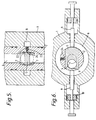
- the gate valve comprises a sliding gate 5 which has a through hole 6 on one side, as best seen in figure 6.
- the gate valve is seated between two seat rings 7 which provide a metal-to-metal seal against the gate and also around the bore 4 of the tubing hanger 2.
- the gate is accommodated in a cavity in the tubing hanger 2 in a plane perpendicular to the bore of the hanger and the spool body 1 is provided with an annular recess 8 which accommodates the gate 5 in the open and closed positions, as shown in figures 1 and 2.
- Two actuating stems 9 are provided, on opposite sides of the gate 5. These extend through the recess 8, respective opposed bores 10 in the wall of the spool body 1, and into respective cylinders 11 which are bolted to the wall of the spool body by bolts 12. Each stem 9 projects through the end of the respective cylinder 11 and is provided with an end stop 13 which abuts against the cylinder 11 when the stem in its innermost position.
- the stem 9 is sealed to the cylinder 11 by annular seal members 14 and to the spool body by a stem packing 15.
- Each stem 9 has an inner part 16 adjacent to the gate, a central part 17 of smaller diameter than the inner part and an outer part 18, remote from gate, of larger diameter than the inner part.
- a piston 19 is slidable on the middle part 17 and is sealed thereto by a seal 20.
- the piston is also slidable within the cylinder 11 and a seal 21 is provided between the outer periphery of the piston 19 and the inner wall of the cylinder 11.
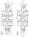
- a first pressure supply line 11A is provided in each cylinder 11 on the side closest to the gate 5 and a second pressure supply line 11B is provided in each case on the side of the cylinder remote from the gate (see figures 3 and 4).
- a detent mechanism 22 is housed in the side of the tubing hanger 2 and has a spring 23 which urges a plunger 24 into contact with the gate.
- the gate has a corresponding recess 24' into which the plunger 24 is urged when the gate 5 is in the intermediate position, as shown in figure 6, in order to retain the gate in this position.
- the gate When the tubing hanger 2 is to be run into or retrieved from the wellhead, the gate has to be brought into the intermediate position as shown in figures 3 and 4.
- pressure is applied to both of the cylinders 11 through the first pressure supply lines 11A in order to force the two pistons 19 into their outermost positions and to force the actuating stems 9 towards the gate.
- the second pressure supply lines 11B act as vents.
- the pistons and actuating stems are moved to the positions shown in figure 3, with a shoulder 26 between the outer part 18 and the central part 17 of the actuating stem abutting against the piston. This brings the gate 5 into the intermediate position.
- FIG. 9 to 12 An alternative example is shown in figures 9 to 12 in which the hydraulic actuation is replaced by manual operation.
- the actuating stems are provided by threaded shafts 27, each of which engages a housing 28 fixed to the spool body 1 and terminates at the end remote from the gate with a handwheel 29.
- the housing 28 which accommodates each actuating stem 27 is provided with an end cap 30. This is adjustable between two positions by virtue of a pair of stubs 31 on the housing 28 each of which is movable along a lazy-Z-shaped slot 32 in the cap 30.
- the end cap 30 When the end cap 30 is in its outer position, the handwheel 29 abuts against it thereby stopping the actuating stem 27 in the intermediate position shown in figures 9 and 10.
- the actuating stem can travel further and move the gate between the open and closed positions as shown in figures 11 and 12.
- the left hand handwheel 29 is moved into its fully unscrewed position and the right hand handwheel 29 is fully screwed in to push the gate 5 into the closed position shown in figure 11. This procedure is reversed to open the gate as shown in figure 12.
Landscapes
- Engineering & Computer Science (AREA)
- General Engineering & Computer Science (AREA)
- Mining & Mineral Resources (AREA)
- Geology (AREA)
- Life Sciences & Earth Sciences (AREA)
- Mechanical Engineering (AREA)
- Environmental & Geological Engineering (AREA)
- Fluid Mechanics (AREA)
- Physics & Mathematics (AREA)
- General Life Sciences & Earth Sciences (AREA)
- Geochemistry & Mineralogy (AREA)
- Sliding Valves (AREA)
- Mechanically-Actuated Valves (AREA)
Description
Claims (12)
- A valve assembly comprising a tubular member (2) which seats, in use, in a support and has an axial bore (4) which is selectively opened and closed by a gate valve, the valve comprising a gate (5) having an opening (6) therethrough, a first actuating stem (9,27) engagable with one side of the gate and reciprocable, in use, through the support, characterised in that it further comprises a second actuating stem (9,27) engageable with the opposite side of the gate and reciprocable, in use, through the support, wherein the actuating stems can move the gate between open and closed positions, and an intermediate position in which the gate can be run into and withdrawn from the support with the tubular member.
- A valve assembly according to claim 1, wherein the gate (5) is retainable in the intermediate position so that the tubular member (2) can be withdrawn from the support without the gate interfering with the support.
- A valve hanger assembly according to claim 2, wherein the gate (5) is retained by means of a detent (22).
- A valve assembly according to claim 3, wherein the detent comprises a spring loaded plunger (24) in one of the tubular member (2) and gate (5), the end of the plunger being engagable with a recess (24') in the other of the tubular member and gate.
- A valve assembly according to any one of the preceding claims, wherein the actuating stems (9,27) project, in use, from the support to provide a visual indication of the position of the gate (5).
- A valve assembly according to any one of the preceding claims, wherein the actuating stems (9,27) are retractable from engagement with the gate (5) when it is in the intermediate position.
- A valve assembly according to any one of the preceding claims, wherein the actuating stems (9,27) are hydraulically actuated.
- A valve assembly according to claim 7 when dependent on claim 6, wherein each actuating stem (9,27) has an inner part (16) adjacent to the gate (5), a central part (17) of smaller diameter than the inner part, and an outer part (18), remote from the gate, of larger diameter than the inner part, and a piston (19) being sealed to and slidably fitted on the central part such that it is retained on the central part and abuts, in use, against the inner or outer parts at respective ends (25,26) of the central part, the piston being sealed to and slidably received in a cylinder, which is fixed, in use, to the support, whereby the application of pressure to the cylinder of one of the actuating stems on the side of the piston remote from the gate causes the gate to be moved to its open position, the application of pressure to the cylinder of the other of the actuating stems on the side of the piston remote from the gate causes the gate to be moved to its closed position, the application of pressure to both cylinders on the side of the piston closest to the gate causes the gate be moved to its intermediate position, and the application of equal pressure to each side of both pistons causes the actuating stems to be retracted from the gate when it is in the intermediate position.
- A valve assembly according to any one of claims 1 to 6, wherein a handwheel (29) is provided on each actuating stem (27) at the end of the stem remote from the gate (5) and each actuating stem is threadably engaged within a housing (28), whereby each handwheel can be rotated to move a respective stem axially.
- A valve assembly according to claim 9, wherein an end cap (30), which provides a stop for the handwheel (29), is fitted over the end of each housing (28), the cap being selectively deployable in two axial positions relative to the axis of the actuating stem.
- A valve assembly according to any one of the preceding claims, wherein a seal ring (7) is provided on each side of the gate which ring seals on one side against the gate (5) and on the other side around the bore (4) of the tubular member (2).
- A valve assembly according to claim 11, wherein the seals between the gate and seal rings, and between the tubular member and seal rings are metal-to-metal seals.
Priority Applications (6)
| Application Number | Priority Date | Filing Date | Title |
|---|---|---|---|
| EP93303626A EP0624711B1 (en) | 1993-05-11 | 1993-05-11 | Valve assembly in wellheads |
| DE69316875T DE69316875T2 (en) | 1993-05-11 | 1993-05-11 | Valve assembly in the wellhead |
| CA002121557A CA2121557A1 (en) | 1993-05-11 | 1994-04-18 | Valve assembly |
| US08/230,935 US5415378A (en) | 1993-05-11 | 1994-04-21 | Valve assembly |
| AU61967/94A AU669976B2 (en) | 1993-05-11 | 1994-05-09 | Valve assembly |
| MXPA94003825A MXPA94003825A (en) | 1993-05-11 | 1994-05-24 | Valve combination. |
Applications Claiming Priority (1)
| Application Number | Priority Date | Filing Date | Title |
|---|---|---|---|
| EP93303626A EP0624711B1 (en) | 1993-05-11 | 1993-05-11 | Valve assembly in wellheads |
Publications (2)
| Publication Number | Publication Date |
|---|---|
| EP0624711A1 EP0624711A1 (en) | 1994-11-17 |
| EP0624711B1 true EP0624711B1 (en) | 1998-02-04 |
Family
ID=8214407
Family Applications (1)
| Application Number | Title | Priority Date | Filing Date |
|---|---|---|---|
| EP93303626A Expired - Lifetime EP0624711B1 (en) | 1993-05-11 | 1993-05-11 | Valve assembly in wellheads |
Country Status (6)
| Country | Link |
|---|---|
| US (1) | US5415378A (en) |
| EP (1) | EP0624711B1 (en) |
| AU (1) | AU669976B2 (en) |
| CA (1) | CA2121557A1 (en) |
| DE (1) | DE69316875T2 (en) |
| MX (1) | MXPA94003825A (en) |
Families Citing this family (29)
| Publication number | Priority date | Publication date | Assignee | Title |
|---|---|---|---|---|
| DE19903831C2 (en) | 1999-02-01 | 2001-03-08 | Satronic Ag | System consisting of an oil pump and a valve for oil burners |
| US6884427B1 (en) * | 1999-02-08 | 2005-04-26 | Aderans Research Institute, Inc. | Filamentary means for introducing agents into tissue of a living host |
| GB9903129D0 (en) | 1999-02-11 | 1999-04-07 | Fmc Corp | Integral gate valve for tubing hangers and the like |
| GB2345927B (en) | 1999-02-11 | 2000-12-13 | Fmc Corp | Subsea completion system with integral valves |
| US20020100592A1 (en) * | 2001-01-26 | 2002-08-01 | Garrett Michael R. | Production flow tree cap |
| AU2001249392A1 (en) * | 2000-03-24 | 2001-10-08 | Fmc Corporation | Gate valve with flow-through gate |
| BRPI0109756B8 (en) | 2000-03-24 | 2015-12-22 | Fmc Technologies | piping support and completion flow system. |
| US7198641B2 (en) * | 2000-08-08 | 2007-04-03 | Aderans Research Institute, Inc. | Scaffolds for tissue engineered hair |
| WO2003004913A1 (en) * | 2001-07-06 | 2003-01-16 | Fmc Technologies, Inc | Small bore gate valve |
| US20040068284A1 (en) * | 2002-01-29 | 2004-04-08 | Barrows Thomas H. | Method for stimulating hair growth and kit for carrying out said method |
| US6964304B2 (en) * | 2002-12-20 | 2005-11-15 | Fmc Technologies, Inc. | Technique for maintaining pressure integrity in a submersible system |
| US7597885B2 (en) * | 2004-03-26 | 2009-10-06 | Aderans Research Institute, Inc. | Tissue engineered biomimetic hair follicle graft |
| AR050212A1 (en) * | 2004-08-13 | 2006-10-04 | Aderans Res Inst Inc | ORGANOGENESIS FROM DISCELLED CELLS |
| EP1996841B1 (en) * | 2006-03-07 | 2013-08-07 | Symutech PTY Limited | A valve |
| GB0721352D0 (en) * | 2007-10-31 | 2007-12-12 | Expro North Sea Ltd | ubsea assembly |
| US9418880B2 (en) * | 2011-06-30 | 2016-08-16 | Semes Co., Ltd. | Apparatuses and methods for treating substrate |
| US8985552B2 (en) * | 2011-12-09 | 2015-03-24 | Vetco Gray Inc. | Lock assembly for hydraulic fracing valve |
| CN103982668B (en) * | 2013-02-07 | 2018-08-28 | Zp因特莱茨有限责任公司 | Gate valve |
| US9091351B2 (en) * | 2013-02-07 | 2015-07-28 | Zp Interests, Llc | Gate valve |
| CN106368648B (en) * | 2015-09-08 | 2019-04-19 | 建湖县鸿达阀门管件有限公司 | A kind of intelligent shale gas device for fracturing wellhead |
| US10260305B2 (en) * | 2015-10-08 | 2019-04-16 | Onesubsea Ip Uk Limited | Completion system with external gate valve |
| GB2566418A (en) | 2016-06-30 | 2019-03-13 | A Bowen Billy JR | Test-port activated tubing hanger control valve |
| CN106812952B (en) * | 2017-03-06 | 2022-10-25 | 深圳市能源环保有限公司 | Waste incineration power plant flue gas bin export piston strutting arrangement |
| US10746132B2 (en) * | 2018-04-27 | 2020-08-18 | United States Of America As Represented By The Administrator Of Nasa | Solenoid-controlled, liquid cryogenic-hydraulically actuated isolation valve assembly |
| US10900575B2 (en) * | 2019-02-28 | 2021-01-26 | Baker Hughes Oilfield Operations Llc | Balanced stem and surface safety valve |
| US11448324B2 (en) * | 2019-05-10 | 2022-09-20 | Vault Pressure Control, Llc | Translating cavity valve |
| US11698138B1 (en) * | 2020-06-09 | 2023-07-11 | Zp Interests, Llc | Gate valve with angled body |
| CN114658872B (en) * | 2022-04-19 | 2023-08-18 | 安徽康迪纳电力科技有限责任公司 | Bidirectional cylinder self-locking pneumatic sealing plugboard door |
| US12110979B1 (en) * | 2022-06-28 | 2024-10-08 | Zp Interests, Llc | Pressure energized gate valve seat and seal assembly |
Family Cites Families (6)
| Publication number | Priority date | Publication date | Assignee | Title |
|---|---|---|---|---|
| US3494377A (en) * | 1967-06-12 | 1970-02-10 | Fmc Corp | Gate valve mechanism for control of plural passages |
| US4010928A (en) * | 1974-12-27 | 1977-03-08 | Xomox Corporation | Piston-operated parallel-slide gate valve |
| EP0124601A1 (en) * | 1982-11-05 | 1984-11-14 | Hydril Company | Safety valve apparatus and method |
| SE445753B (en) * | 1984-12-05 | 1986-07-14 | Asea Atom Ab | Well head valve for oil cell under the water |
| US4809733A (en) * | 1987-04-22 | 1989-03-07 | National-Oilwell | Fail-safe gate valve with separated actuators |
| US4934652A (en) * | 1989-12-11 | 1990-06-19 | Otis Engineering Corporation | Dual stage valve actuator |
-
1993
- 1993-05-11 DE DE69316875T patent/DE69316875T2/en not_active Expired - Fee Related
- 1993-05-11 EP EP93303626A patent/EP0624711B1/en not_active Expired - Lifetime
-
1994
- 1994-04-18 CA CA002121557A patent/CA2121557A1/en not_active Abandoned
- 1994-04-21 US US08/230,935 patent/US5415378A/en not_active Expired - Fee Related
- 1994-05-09 AU AU61967/94A patent/AU669976B2/en not_active Ceased
- 1994-05-24 MX MXPA94003825A patent/MXPA94003825A/en unknown
Also Published As
| Publication number | Publication date |
|---|---|
| EP0624711A1 (en) | 1994-11-17 |
| DE69316875T2 (en) | 1998-08-13 |
| CA2121557A1 (en) | 1994-11-12 |
| AU6196794A (en) | 1994-11-24 |
| US5415378A (en) | 1995-05-16 |
| DE69316875D1 (en) | 1998-03-12 |
| AU669976B2 (en) | 1996-06-27 |
| MXPA94003825A (en) | 2004-03-31 |
Similar Documents
| Publication | Publication Date | Title |
|---|---|---|
| EP0624711B1 (en) | Valve assembly in wellheads | |
| CA1294599C (en) | Modular hydraulic actuator | |
| US4650151A (en) | Subsea gate valve actuator with external manual override and drift adjustment | |
| US4809733A (en) | Fail-safe gate valve with separated actuators | |
| EP1278933B1 (en) | Internal gate valve for flow completion systems | |
| EP0786044B1 (en) | Subsurface safety valve of minimized length | |
| US5226483A (en) | Safety valve landing nipple and method | |
| CA1260384A (en) | Subsea master valve for use in well testing | |
| EP1278934B1 (en) | Tubing hanger system with gate valve | |
| US4519575A (en) | Valves and valve actuators | |
| US20050087712A1 (en) | Mechanical override for a valve actuator | |
| GB2287263A (en) | Tubing hangers | |
| AU2001249385A1 (en) | Internal gate valve for flow completion systems | |
| GB2047304A (en) | Piston actuated well safety valve | |
| EP3740651B1 (en) | Subsea actuator with override function, as well as a method of operating an actuator | |
| CA2160817C (en) | Subsurface safety valve | |
| US6231027B1 (en) | High torque rotating actuator | |
| US6845958B2 (en) | Wireline valve actuator | |
| EP0495747B1 (en) | Gas spring actuator | |
| US4519571A (en) | Fluid operated, axially reciprocating actuator | |
| US4817669A (en) | Control valve | |
| US6964304B2 (en) | Technique for maintaining pressure integrity in a submersible system | |
| EP1282794B1 (en) | Combination poppet and gate valve | |
| EP2630323B1 (en) | Apparatus and methods for restricting flow in a bore | |
| GB2323872A (en) | Subsurface safety valve having non-metallic, non-elastomeric seals |
Legal Events
| Date | Code | Title | Description |
|---|---|---|---|
| PUAI | Public reference made under article 153(3) epc to a published international application that has entered the european phase |
Free format text: ORIGINAL CODE: 0009012 |
|
| AK | Designated contracting states |
Kind code of ref document: A1 Designated state(s): DE FR GB NL |
|
| 17P | Request for examination filed |
Effective date: 19950426 |
|
| RAP1 | Party data changed (applicant data changed or rights of an application transferred) |
Owner name: COOPER CAMERON CORPORATION |
|
| GRAG | Despatch of communication of intention to grant |
Free format text: ORIGINAL CODE: EPIDOS AGRA |
|
| 17Q | First examination report despatched |
Effective date: 19970320 |
|
| GRAG | Despatch of communication of intention to grant |
Free format text: ORIGINAL CODE: EPIDOS AGRA |
|
| GRAH | Despatch of communication of intention to grant a patent |
Free format text: ORIGINAL CODE: EPIDOS IGRA |
|
| GRAH | Despatch of communication of intention to grant a patent |
Free format text: ORIGINAL CODE: EPIDOS IGRA |
|
| GRAA | (expected) grant |
Free format text: ORIGINAL CODE: 0009210 |
|
| AK | Designated contracting states |
Kind code of ref document: B1 Designated state(s): DE FR GB NL |
|
| REF | Corresponds to: |
Ref document number: 69316875 Country of ref document: DE Date of ref document: 19980312 |
|
| ET | Fr: translation filed | ||
| PLBE | No opposition filed within time limit |
Free format text: ORIGINAL CODE: 0009261 |
|
| STAA | Information on the status of an ep patent application or granted ep patent |
Free format text: STATUS: NO OPPOSITION FILED WITHIN TIME LIMIT |
|
| 26N | No opposition filed | ||
| REG | Reference to a national code |
Ref country code: GB Ref legal event code: IF02 |
|
| PGFP | Annual fee paid to national office [announced via postgrant information from national office to epo] |
Ref country code: NL Payment date: 20030403 Year of fee payment: 11 |
|
| PGFP | Annual fee paid to national office [announced via postgrant information from national office to epo] |
Ref country code: FR Payment date: 20030505 Year of fee payment: 11 |
|
| PGFP | Annual fee paid to national office [announced via postgrant information from national office to epo] |
Ref country code: DE Payment date: 20040528 Year of fee payment: 12 |
|
| PG25 | Lapsed in a contracting state [announced via postgrant information from national office to epo] |
Ref country code: NL Free format text: LAPSE BECAUSE OF NON-PAYMENT OF DUE FEES Effective date: 20041201 |
|
| PG25 | Lapsed in a contracting state [announced via postgrant information from national office to epo] |
Ref country code: FR Free format text: LAPSE BECAUSE OF NON-PAYMENT OF DUE FEES Effective date: 20050131 |
|
| NLV4 | Nl: lapsed or anulled due to non-payment of the annual fee |
Effective date: 20041201 |
|
| REG | Reference to a national code |
Ref country code: FR Ref legal event code: ST |
|
| PG25 | Lapsed in a contracting state [announced via postgrant information from national office to epo] |
Ref country code: DE Free format text: LAPSE BECAUSE OF NON-PAYMENT OF DUE FEES Effective date: 20051201 |
|
| PGFP | Annual fee paid to national office [announced via postgrant information from national office to epo] |
Ref country code: GB Payment date: 20120426 Year of fee payment: 20 |
|
| REG | Reference to a national code |
Ref country code: GB Ref legal event code: PE20 Expiry date: 20130510 |
|
| PG25 | Lapsed in a contracting state [announced via postgrant information from national office to epo] |
Ref country code: GB Free format text: LAPSE BECAUSE OF EXPIRATION OF PROTECTION Effective date: 20130510 |