EP0623724A1 - Panel, and also a hinge section which is suitable, inter alia, for such a panel - Google Patents
Panel, and also a hinge section which is suitable, inter alia, for such a panel Download PDFInfo
- Publication number
- EP0623724A1 EP0623724A1 EP94201251A EP94201251A EP0623724A1 EP 0623724 A1 EP0623724 A1 EP 0623724A1 EP 94201251 A EP94201251 A EP 94201251A EP 94201251 A EP94201251 A EP 94201251A EP 0623724 A1 EP0623724 A1 EP 0623724A1
- Authority
- EP
- European Patent Office
- Prior art keywords
- wall
- hinge
- panel
- section
- arc
- Prior art date
- Legal status (The legal status is an assumption and is not a legal conclusion. Google has not performed a legal analysis and makes no representation as to the accuracy of the status listed.)
- Granted
Links
- 230000001154 acute effect Effects 0.000 claims abstract description 10
- 230000004308 accommodation Effects 0.000 claims abstract 3
- 230000007704 transition Effects 0.000 claims description 12
- 229920003023 plastic Polymers 0.000 claims description 10
- 239000004033 plastic Substances 0.000 claims description 10
- 238000007789 sealing Methods 0.000 claims description 6
- 238000004873 anchoring Methods 0.000 claims description 5
- 239000006260 foam Substances 0.000 claims description 4
- 238000004891 communication Methods 0.000 claims description 3
- 230000002787 reinforcement Effects 0.000 claims description 2
- 239000011324 bead Substances 0.000 claims 1
- 239000011796 hollow space material Substances 0.000 claims 1
- 238000001125 extrusion Methods 0.000 description 4
- 238000000034 method Methods 0.000 description 3
- 229920005830 Polyurethane Foam Polymers 0.000 description 2
- 238000004519 manufacturing process Methods 0.000 description 2
- 239000011496 polyurethane foam Substances 0.000 description 2
- 230000000284 resting effect Effects 0.000 description 2
- 238000010924 continuous production Methods 0.000 description 1
- 230000008014 freezing Effects 0.000 description 1
- 238000007710 freezing Methods 0.000 description 1
- 238000003780 insertion Methods 0.000 description 1
- 230000037431 insertion Effects 0.000 description 1
- 238000005461 lubrication Methods 0.000 description 1
- 230000035515 penetration Effects 0.000 description 1
- 229920002635 polyurethane Polymers 0.000 description 1
- 239000004814 polyurethane Substances 0.000 description 1
Images


Classifications
-
- E—FIXED CONSTRUCTIONS
- E06—DOORS, WINDOWS, SHUTTERS, OR ROLLER BLINDS IN GENERAL; LADDERS
- E06B—FIXED OR MOVABLE CLOSURES FOR OPENINGS IN BUILDINGS, VEHICLES, FENCES OR LIKE ENCLOSURES IN GENERAL, e.g. DOORS, WINDOWS, BLINDS, GATES
- E06B3/00—Window sashes, door leaves, or like elements for closing wall or like openings; Layout of fixed or moving closures, e.g. windows in wall or like openings; Features of rigidly-mounted outer frames relating to the mounting of wing frames
- E06B3/32—Arrangements of wings characterised by the manner of movement; Arrangements of movable wings in openings; Features of wings or frames relating solely to the manner of movement of the wing
- E06B3/48—Wings connected at their edges, e.g. foldable wings
- E06B3/485—Sectional doors
- E06B3/486—Sectional doors with hinges being at least partially integral part of the section panels
-
- E—FIXED CONSTRUCTIONS
- E05—LOCKS; KEYS; WINDOW OR DOOR FITTINGS; SAFES
- E05D—HINGES OR SUSPENSION DEVICES FOR DOORS, WINDOWS OR WINGS
- E05D15/00—Suspension arrangements for wings
- E05D15/16—Suspension arrangements for wings for wings sliding vertically more or less in their own plane
- E05D15/24—Suspension arrangements for wings for wings sliding vertically more or less in their own plane consisting of parts connected at their edges
- E05D15/242—Hinge connections between the parts
-
- E—FIXED CONSTRUCTIONS
- E06—DOORS, WINDOWS, SHUTTERS, OR ROLLER BLINDS IN GENERAL; LADDERS
- E06B—FIXED OR MOVABLE CLOSURES FOR OPENINGS IN BUILDINGS, VEHICLES, FENCES OR LIKE ENCLOSURES IN GENERAL, e.g. DOORS, WINDOWS, BLINDS, GATES
- E06B3/00—Window sashes, door leaves, or like elements for closing wall or like openings; Layout of fixed or moving closures, e.g. windows in wall or like openings; Features of rigidly-mounted outer frames relating to the mounting of wing frames
- E06B3/32—Arrangements of wings characterised by the manner of movement; Arrangements of movable wings in openings; Features of wings or frames relating solely to the manner of movement of the wing
- E06B3/48—Wings connected at their edges, e.g. foldable wings
- E06B3/485—Sectional doors
-
- E—FIXED CONSTRUCTIONS
- E04—BUILDING
- E04F—FINISHING WORK ON BUILDINGS, e.g. STAIRS, FLOORS
- E04F2201/00—Joining sheets or plates or panels
- E04F2201/01—Joining sheets, plates or panels with edges in abutting relationship
- E04F2201/0153—Joining sheets, plates or panels with edges in abutting relationship by rotating the sheets, plates or panels around an axis which is parallel to the abutting edges, possibly combined with a sliding movement
-
- E—FIXED CONSTRUCTIONS
- E05—LOCKS; KEYS; WINDOW OR DOOR FITTINGS; SAFES
- E05D—HINGES OR SUSPENSION DEVICES FOR DOORS, WINDOWS OR WINGS
- E05D1/00—Pinless hinges; Substitutes for hinges
- E05D1/04—Pinless hinges; Substitutes for hinges with guide members shaped as circular arcs
-
- E—FIXED CONSTRUCTIONS
- E05—LOCKS; KEYS; WINDOW OR DOOR FITTINGS; SAFES
- E05Y—INDEXING SCHEME ASSOCIATED WITH SUBCLASSES E05D AND E05F, RELATING TO CONSTRUCTION ELEMENTS, ELECTRIC CONTROL, POWER SUPPLY, POWER SIGNAL OR TRANSMISSION, USER INTERFACES, MOUNTING OR COUPLING, DETAILS, ACCESSORIES, AUXILIARY OPERATIONS NOT OTHERWISE PROVIDED FOR, APPLICATION THEREOF
- E05Y2800/00—Details, accessories and auxiliary operations not otherwise provided for
- E05Y2800/40—Physical or chemical protection
- E05Y2800/41—Physical or chemical protection against finger injury
-
- E—FIXED CONSTRUCTIONS
- E05—LOCKS; KEYS; WINDOW OR DOOR FITTINGS; SAFES
- E05Y—INDEXING SCHEME ASSOCIATED WITH SUBCLASSES E05D AND E05F, RELATING TO CONSTRUCTION ELEMENTS, ELECTRIC CONTROL, POWER SUPPLY, POWER SIGNAL OR TRANSMISSION, USER INTERFACES, MOUNTING OR COUPLING, DETAILS, ACCESSORIES, AUXILIARY OPERATIONS NOT OTHERWISE PROVIDED FOR, APPLICATION THEREOF
- E05Y2900/00—Application of doors, windows, wings or fittings thereof
- E05Y2900/10—Application of doors, windows, wings or fittings thereof for buildings or parts thereof
- E05Y2900/106—Application of doors, windows, wings or fittings thereof for buildings or parts thereof for garages
Definitions
- the present invention relates to a panel according to the preamble of Claim 1.
- Such a panel is used for, for example, vertically movable articulated garage doors, but can equally be used for horizontally movable articulated doors, which are also known as sectional doors, and in the case of which the adjacent panels have to be able to carry out a specific mutual rotation in order to be able to move the door through an angle of, for example, 90°.
- a panel of this type is known, for example from GB-A-2157752.
- a major disadvantage of this known panel is that when the panels are rotated relative to each other a gap-shaped space is produced between the adjacent panels, which gap closes when the adjacent panels are returned to lie in a common plane.
- Such a gap means that, particularly in the case of horizontally moving doors, there is a risk of putting one's fingers into the opening and closing gap, and of the fingers becoming trapped, with the serious consequences which this can entail.
- Sectional doors with so-called finger protection are currently known. These doors are generally made of panels whose narrow long sides are formed in such a way that the gap arising is too small to be a hazard. The panels in this case are connected to each other by separate hinges. Such doors are complex and are time-consuming to fit.
- the object of the present invention is then to provide a panel with hinge incorporated therein, which panel is simple in design, and in the case of which the adjacent panels can pivot relative to each other without the risk of fingers becoming trapped between the panels.
- the shape of the hinge parts therefore provides the desired finger protection, on the one hand, and a suitable hinged connection with the desired strength and stability, on the other.
- the first and the second hinge parts are each formed as individual section parts, for example by extrusion, and the parts are then combined with the plates to form a panel, the interior of the panel being foamed up with foam-type plastic such as polyurethane.
- a panel produced by this method is distinguished by the features described in Claim 5.
- the interior of each section part is in communication with the space between the plates by way of the gap-shaped opening in the bottom wall, so that the interior of the section part is effectively filled up with foam plastic and thereby acquires the desired strength.
- the anchoring means combined with the foam plastic in this case provide a good connection between the section parts and the plates of the body part.
- Claims 6 - 9 indicate other efficient features of panels produced by this method.
- the hinge parts are formed in a roll-forming operation so that they are in one piece with the respective plates of the body part.
- the plates are designed as described in Claims 10 and 11.
- the two plates need only be placed on top of one another, and the respective connecting edges of the plates come to rest against each other. The interior space between the plates is then foamed up. In the case of this last method, the panels can be made cheaply in a continuous process.
- hinge section 13 An expedient variant of the hinge section according to the invention is described in the independent Claim 13. Such a finger-protecting hinge section can be used effectively in interior doors or cupboard doors.
- FIGS 1 and 2 show in cross-section the hinged connection between two identical panels 1 and 1'. These are in fact panels of the type in current use for the production of so-called sectional doors, used as garage doors or as doors for factory halls and/or stores.
- the panels here are each elongated in shape and are made up of two parallel side plates 2, 2' which are spaced apart and along the long narrow sides enclose between them a hinge part 3, 4 respectively.
- the two hinge parts are formed here as separate section parts produced by extrusion. It will be clear that each panel has a hinge part 3 along one narrow side and a hinge part 4 along the other narrow side, so that a succession of hingedly connected panels can be formed by always hooking the hinge parts 3 and 4 into each other in a manner which is known per se.
- Each bottom wall 6; 6' has a longitudinal gap-shaped opening 9; 9', the side edges of which are each provided with a flange 10, 11; 10', 11', extending from the bottom wall 6; 6' in a direction opposite to that of said side walls.
- the flanges 10, 11; 10', 11' each contain a rectilinear part diverging from the gap-shaped opening, against which part a flanged edge part of the side plates 2, 2' always rests. After this diverging part, the flanges run in a corrugated or stepped shape over some distance in the space between the two side plates 2, 2'.
- each hinge part which is surrounded by the bottom wall, the side walls and the wall forming the hinge, is in communication with the space between the side plates 2, 2'.
- foam-type plastic for example polyurethane foam
- the interior space of the hinge parts is also filled with this foam-type plastic.
- the flanges 10, 11; 10', 11' are shaped in such a way that they do not impede the flow of the foam-type plastic into the hinge parts.
- the flanges also ensure a firm anchoring of the hinge parts to the side plates, while the hinge parts themselves acquire additional strength and stability from the foam-type plastic.
- the hinge part 3 has an arc-shaped nose, which is formed by an arc-shaped outside wall 12, which connects by means of a transitional area to the side wall 8, and at the free end of the nose runs back into an arc-shaped inside wall 13 running coaxially at a distance from the outside wall 12 and then merging through a rounded acute angle into the other side wall 7. In this way the nose extends over the full width of the hinge part 3.
- the cylindrical thickened part 14 is provided with a recess 18, which serves for the insertion of said thickened part into the cavity formed by the nose of the other hinge part 3.
- the hinge parts 3 and 4 are dimensioned in such a way that in the combined state shown in the drawing the thickened part 14 fits closely into the cavity formed by the inside wall 13 of the nose, while the outside wall 12 of the nose rests against the arc-shaped wall 17 of the other hinge part 4. Since the wall 17 merges through a rounded acute angle into the wall 8', and the outside wall 12 of the nose merges gradually into the side wall 8, when the panels are rotated relative to each other no gap in which a finger can be caught is produced.
- a finger 19 is shown in Figure 1 in order to illustrate this.
- the hinge part 3 is provided with a sealing lip 20 extending over the full longitudinal length of the panel.
- This lip is made of a flexible soft plastic and in the position of the panels 1, 1' shown in figure 2 shuts off the gap between the hinge parts 3 and 4 in order to prevent the penetration of rainwater and/or dirt.
- the sealing lip is preferably produced by co-extrusion during the extrusion of the section part.
- the outside wall 12 of the nose is staggered inwards slightly relative to the side wall 8 and merges into said wall through a transitional area in the form of a shallow S-bend. This is necessary in order to make the arc-shaped wall 17 of the other hinge part 4 continue as far as possible.
- the rounded acute angle through which the wall 17 merges into the side wall 8' lies at least above the face 14a which is at right angles to the face of the panel 1' and runs through the axis 14' of the thickened part 14 (see Fig. 2). This ensures that the outside wall 12 of the nose remains in contact with the wall 17 of the other hinge part when the two panels have been rotated through the maximum possible angle relative to each other. In this position of the panels also, the protection of the fingers is then maintained.
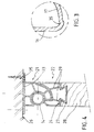
- Fig. 3 shows the detail III in Fig. 1 on a greatly enlarged scale.
- This detail shows the transition of the wall 16 of the supporting part into the arc-shaped wall 17.
- a tapered recess 35 forming a longitudinal channel, is provided on this transition. Any moisture which has collected in the hinge section can flow away along this channel to the sides of the panel.
- Figure 4 shows a variant of the hinge section according to the invention which can be used as a hinge for an inside door or cupboard door.
- the two section parts 21 and 22 have essentially the same configuration as the hinge parts in Figures 1 and 2.
- the same reference numbers are therefore used as far as possible for the same or corresponding parts.
- the cylindrical thickened part 14 has no recess 18 for hooking the section parts 21 and 22 into each other.
- the section parts 21 and 22 therefore have to be slid axially into each other in this embodiment.
- each hinge part 21 and 22 is provided with a number of inside reinforcement walls 29, in order to provide the necessary stability and strength.
- FIG. 5 shows another embodiment of the panel according to the invention, in which the hinge parts are not made as separate section parts, but are formed in a roll-forming operation directly in the long side edges of the plates 30, 30' of the panel.
- the two plates 30, 30' are shown a slight distance apart in this figure.
- the plate 30 contains a part of the hinge part 4, i.e. the inward-slanting wall 15, which continues through a suitable rounded part into the cylindrical thickened part 14.
- the plate 30 contains a part of the hinge part 3, i.e. the internal arc-shaped inside wall 13 of the nose to which a straight connecting edge 31 connects, which edge runs parallel to the plane of the plate.
- the plate 30' also contains the remaining part of the hinge part 4 at one long side, i.e. the arc-shaped wall 17 and the wall 16 of the supporting part.
- a straight connecting edge 32 which runs parallel to the slanting wall 15 of the other plate when the plates are combined, connects to the wall 16.
- the plate 30' contains the arc-shaped outside wall 12 of the nose, to which a connecting edge 33 running parallel to the plane of the plate subsequently connects.
- the two plates 30, 30' are combined, at one side the connecting edge 32 resting against the slanting wall 15, and at the other side the two connecting edges 31 and 33 resting against each other.
- the interior space between the two plates is then foamed up with e.g. polyurethane foam. Due to the fact that the two plates 30, 30' are made by roll-forming, the shape at less important points can deviate slightly from the embodiment described above.
- the outside wall 12 of the nose thus contains a recess 34 near the connection to the flat part of the plate, which recess serves to accommodate a sealing strip which has the same function as the sealing strip 20 of the previous embodiment.
- the transition area between the side wall 8 and the outside wall 12 of the nose is in the form of a shallow S-bend in the first embodiment.
- This transition area could also be designed differently, e.g. with large radii of curvature or with obtuse angles, or it could even be a continuous transition.
- the arc-shaped faces 12 and 17 of the nose can also be provided with grooves several tenths of a millimetre deep, running in the longitudinal direction of the panel. These grooves, which are not shown in the drawing, serve for lubrication purposes and for preventing the panels from freezing up.
Landscapes
- Engineering & Computer Science (AREA)
- Civil Engineering (AREA)
- Structural Engineering (AREA)
- Mechanical Engineering (AREA)
- Securing Of Glass Panes Or The Like (AREA)
- Hinges (AREA)
- Extensible Doors And Revolving Doors (AREA)
- Laminated Bodies (AREA)
Abstract
Description
- The present invention relates to a panel according to the preamble of Claim 1.
- Such a panel is used for, for example, vertically movable articulated garage doors, but can equally be used for horizontally movable articulated doors, which are also known as sectional doors, and in the case of which the adjacent panels have to be able to carry out a specific mutual rotation in order to be able to move the door through an angle of, for example, 90°. A panel of this type is known, for example from GB-A-2157752.
- A major disadvantage of this known panel is that when the panels are rotated relative to each other a gap-shaped space is produced between the adjacent panels, which gap closes when the adjacent panels are returned to lie in a common plane. Such a gap means that, particularly in the case of horizontally moving doors, there is a risk of putting one's fingers into the opening and closing gap, and of the fingers becoming trapped, with the serious consequences which this can entail.
- Sectional doors with so-called finger protection are currently known. These doors are generally made of panels whose narrow long sides are formed in such a way that the gap arising is too small to be a hazard. The panels in this case are connected to each other by separate hinges. Such doors are complex and are time-consuming to fit.
- The object of the present invention is then to provide a panel with hinge incorporated therein, which panel is simple in design, and in the case of which the adjacent panels can pivot relative to each other without the risk of fingers becoming trapped between the panels. These objects are achieved according to the invention by a panel which has the features described in Claim 1.
- Due to the fact that the arc-shaped external surface of the nose and the arc-shaped wall of the other hinge part interacting therewith both continue virtually to the respective side walls of the panel, no opening and closing gap is now produced when the adjacent panels rotate relative to each other, or in any case the gap is too small for there to be a risk of fingers becoming trapped in it. The shape of the hinge parts therefore provides the desired finger protection, on the one hand, and a suitable hinged connection with the desired strength and stability, on the other.
- In a first embodiment of the invention, the first and the second hinge parts are each formed as individual section parts, for example by extrusion, and the parts are then combined with the plates to form a panel, the interior of the panel being foamed up with foam-type plastic such as polyurethane. A panel produced by this method is distinguished by the features described in Claim 5. The interior of each section part is in communication with the space between the plates by way of the gap-shaped opening in the bottom wall, so that the interior of the section part is effectively filled up with foam plastic and thereby acquires the desired strength. The anchoring means combined with the foam plastic in this case provide a good connection between the section parts and the plates of the body part. Claims 6 - 9 indicate other efficient features of panels produced by this method.
- In a second embodiment of the panels according to the invention, the hinge parts are formed in a roll-forming operation so that they are in one piece with the respective plates of the body part. In order to make this roll-forming possible, the plates are designed as described in
Claims - The idea of the invention is also embodied in a hinge section which is obviously intended for use in the production of a panel according to Claims 5 - 9.
- An expedient variant of the hinge section according to the invention is described in the
independent Claim 13. Such a finger-protecting hinge section can be used effectively in interior doors or cupboard doors. - The invention will be explained in greater detail below with reference to the appended drawing, in which:
- Fig. 1 shows a cross-section of the hinged connection between two adjacent panels according to the invention, in which the panels are rotated slightly relative to each other;
- Fig. 2 shows a cross-section corresponding to that of Figure 1, in which the two panels lie in a common plane;
- Fig. 3 shows on a greatly enlarged scale the detail III from Fig. 1;
- Fig. 4 shows a variant of the hinge section according to the invention; and
- Fig. 5 shows a variant of the panel according to the invention, in which the hinge parts are made integral with the side plates.
- The same parts or parts having the same function are indicated as far as possible by the same reference numbers in the various figures.
- Figures 1 and 2 show in cross-section the hinged connection between two
identical panels 1 and 1'. These are in fact panels of the type in current use for the production of so-called sectional doors, used as garage doors or as doors for factory halls and/or stores. The panels here are each elongated in shape and are made up of twoparallel side plates 2, 2' which are spaced apart and along the long narrow sides enclose between them ahinge part 3, 4 respectively. The two hinge parts are formed here as separate section parts produced by extrusion. It will be clear that each panel has a hinge part 3 along one narrow side and ahinge part 4 along the other narrow side, so that a succession of hingedly connected panels can be formed by always hooking thehinge parts 3 and 4 into each other in a manner which is known per se. - Each hinge part 3; 4 has a
bottom wall 6; 6' with twoside walls 7, 8; 7', 8' positioned at right angles thereto and lying in line with therespective side plates 2, 2'. The two side walls are again connected to each other at their ends facing away from the bottom wall by way of a wall which forms the actual hinge, and the shape of which will be described in detail below. - Each
bottom wall 6; 6' has a longitudinal gap-shaped opening 9; 9', the side edges of which are each provided with aflange bottom wall 6; 6' in a direction opposite to that of said side walls. Theflanges side plates 2, 2' always rests. After this diverging part, the flanges run in a corrugated or stepped shape over some distance in the space between the twoside plates 2, 2'. By way of the gap-shaped opening 9, 9' the interior space of each hinge part, which is surrounded by the bottom wall, the side walls and the wall forming the hinge, is in communication with the space between theside plates 2, 2'. When the space between theside plates 2, 2' is filled up with foam-type plastic, for example polyurethane foam, the interior space of the hinge parts is also filled with this foam-type plastic. For this purpose, theflanges - As can be seen clearly from the drawing, the hinge part 3 has an arc-shaped nose, which is formed by an arc-shaped
outside wall 12, which connects by means of a transitional area to theside wall 8, and at the free end of the nose runs back into an arc-shaped insidewall 13 running coaxially at a distance from theoutside wall 12 and then merging through a rounded acute angle into the other side wall 7. In this way the nose extends over the full width of the hinge part 3. - Near one side wall 7', the
other hinge part 4 has a cylindrical thickened part or hingepin 14, which is intended for placing in a close fit in the cavity formed by theinside wall 13 of the nose. The thickened part is supported by a supporting part, which is formed by an inwardslanting extension 15 of the side wall 7' and awall part 16 running virtually parallel to the side wall 7' and at a distance therefrom. Thewall part 16 merges through a rounded angle into an arc-shaped wall 17, which in turn runs concentrically at a distance from the cylindrical thickenedpart 14, whichwall 17 continues to the other side wall 8' and merges into it through a rounded acute angle. - At the side facing the side wall 7', the cylindrical thickened
part 14 is provided with arecess 18, which serves for the insertion of said thickened part into the cavity formed by the nose of the other hinge part 3. As can be seen clearly in the drawing, thehinge parts 3 and 4 are dimensioned in such a way that in the combined state shown in the drawing the thickenedpart 14 fits closely into the cavity formed by theinside wall 13 of the nose, while theoutside wall 12 of the nose rests against the arc-shaped wall 17 of theother hinge part 4. Since thewall 17 merges through a rounded acute angle into the wall 8', and theoutside wall 12 of the nose merges gradually into theside wall 8, when the panels are rotated relative to each other no gap in which a finger can be caught is produced. Afinger 19 is shown in Figure 1 in order to illustrate this. - As shown in Figures 1 and 2, near the transition of the
side wall 8 into the arc-shaped wall 12, the hinge part 3 is provided with asealing lip 20 extending over the full longitudinal length of the panel. This lip is made of a flexible soft plastic and in the position of thepanels 1, 1' shown in figure 2 shuts off the gap between thehinge parts 3 and 4 in order to prevent the penetration of rainwater and/or dirt. The sealing lip is preferably produced by co-extrusion during the extrusion of the section part. - The
outside wall 12 of the nose is staggered inwards slightly relative to theside wall 8 and merges into said wall through a transitional area in the form of a shallow S-bend. This is necessary in order to make the arc-shaped wall 17 of theother hinge part 4 continue as far as possible. According to the invention, the rounded acute angle through which thewall 17 merges into the side wall 8' lies at least above the face 14a which is at right angles to the face of thepanel 1' and runs through the axis 14' of the thickened part 14 (see Fig. 2). This ensures that theoutside wall 12 of the nose remains in contact with thewall 17 of the other hinge part when the two panels have been rotated through the maximum possible angle relative to each other. In this position of the panels also, the protection of the fingers is then maintained. - Fig. 3 shows the detail III in Fig. 1 on a greatly enlarged scale. This detail shows the transition of the
wall 16 of the supporting part into the arc-shapedwall 17. As can be seen from this detail, atapered recess 35, forming a longitudinal channel, is provided on this transition. Any moisture which has collected in the hinge section can flow away along this channel to the sides of the panel. - Finally, Figure 4 shows a variant of the hinge section according to the invention which can be used as a hinge for an inside door or cupboard door. As regards the hinge action, the two
section parts part 14 has norecess 18 for hooking thesection parts section parts - However, the essential difference from the hinge parts of Figures 1 and 2 is the shape of the
bottom walls respective section parts bottom wall 23 of thesection part 21 consists of a flat closed wall running past theside walls 7 and 8 in order to form side flanges, by means of which this section part can be fixed to awall 26, for example by means ofscrews 25. Thebottom wall 24 of theother section part 22 also consists of a closed wall which between the side walls 7' and 8' of the hinge part is provided with adovetailed projection 27, by means of which thesection part 22 can be connected to adoor leaf 28 or the like. This produces a hinged door with a finger-protecting hinge section extending over the entire height of the door. Since the interior space of said hinge section is not filled up with foam plastic, each hingepart inside reinforcement walls 29, in order to provide the necessary stability and strength. - Figure 5 shows another embodiment of the panel according to the invention, in which the hinge parts are not made as separate section parts, but are formed in a roll-forming operation directly in the long side edges of the
plates 30, 30' of the panel. For the sake of clarity, the twoplates 30, 30' are shown a slight distance apart in this figure. - As can be seen from this figure, at one long side the
plate 30 contains a part of thehinge part 4, i.e. the inward-slantingwall 15, which continues through a suitable rounded part into the cylindrical thickenedpart 14. At the other long side, theplate 30 contains a part of the hinge part 3, i.e. the internal arc-shaped insidewall 13 of the nose to which a straight connectingedge 31 connects, which edge runs parallel to the plane of the plate. - The plate 30' also contains the remaining part of the
hinge part 4 at one long side, i.e. the arc-shapedwall 17 and thewall 16 of the supporting part. A straight connectingedge 32, which runs parallel to the slantingwall 15 of the other plate when the plates are combined, connects to thewall 16. At the other long side, the plate 30' contains the arc-shaped outsidewall 12 of the nose, to which a connectingedge 33 running parallel to the plane of the plate subsequently connects. - The two
plates 30, 30' are combined, at one side the connectingedge 32 resting against the slantingwall 15, and at the other side the two connectingedges plates 30, 30' are made by roll-forming, the shape at less important points can deviate slightly from the embodiment described above. Theoutside wall 12 of the nose thus contains arecess 34 near the connection to the flat part of the plate, which recess serves to accommodate a sealing strip which has the same function as the sealingstrip 20 of the previous embodiment. - It will be clear that the invention is not limited to the embodiment illustrated and described here, but that a large number of other variants are possible within the scope of the appended claims. For example, the means by which the
hinge parts - The transition area between the
side wall 8 and theoutside wall 12 of the nose is in the form of a shallow S-bend in the first embodiment. This transition area could also be designed differently, e.g. with large radii of curvature or with obtuse angles, or it could even be a continuous transition. - Finally, the arc-shaped
faces
Claims (15)
- Panel (1, 1'), in particular for forming a garage door or the like, comprising an elongated body part which at one long narrow side is provided with a first hinge part (4) extending over the full length of the panel, and at the other narrow side is provided with a second hinge part (3), likewise extending over the full length of the panel, the second hinge part having an arc-shaped nose, and the first hinge part having an arc-shaped thickened part (14) (hinge pin) and, running coaxially at a distance therefrom, an arc-shaped wall (17), which wall around said thickened part leaves a space free for the accommodation of a nose of the second hinge part of an adjacent panel, which nose can grip around said thickened part, in order to form a hinged connection between adjacent panels, and the large side walls of the body part being formed by two essentially flat parallel plates (2, 2'; 30, 30') lying at a distance from each other, and with the space between them filled up with a foam plastic, characterized in that the arc-shaped outside wall (12) of the nose of the second hinge part (3) extends essentially from one side wall (2', 30') of the panel, while the coaxial inside wall (13) of said nose ends near the other side wall (2, 30) of the panel, and in that the cylindrical thickened part (14) of the first hinge part (4) lies on a supporting part (15, 16) adjoining the abovementioned other side wall (2, 30), and the arc-shaped wall (17) extends from the foot of said supporting part to the abovementioned one side wall (2', 30') of the panel and merges through a rounded acute angle into said one side wall.
- Panel according to Claim 1, characterized in that at the first hinge part the transition between the arc-shaped wall and the one side wall lies in or past the plane running through the axis (14a) of the thickened part (hinge pin) and running at right angles to the general plane of the panel.
- Panel according to Claim 1 or 2, characterized in that the outside wall (12) of the nose of the second hinge part is provided with a sealing strip (20) near the transition with the adjacent side wall of the panel.
- Panel according to the preceding Claims 1 - 3, characterized in that the cylindrical thickened part (14) is provided with a notch (18), which at one side is formed by a continuation of the inward-slanting wall part (15) of the supporting part, which continuation runs back through a rounded acute angle to the circular wall of the thickened part.
- Panel according to the preceding Claims 1 - 4, in which the first and the second hinge part are formed as separate section parts which are combined with the plates of the body part, characterized in that each hinge part is formed by a bottom wall (6, 6') with two side walls (7, 8; 7', 8') at right angles thereto, each connecting in an essentially flat manner to the plates (2, 2') of the body part, while the bottom wall is provided with a longitudinal gap-shaped opening (9, 9'), through which opening the interior hollow space of the hinge part is in communication with the space between the plates of the body part, and the bottom wall is also provided with anchoring means (10, 11; 10', 11') extending from the bottom wall until they are between the plates of the body part.
- Panel according to Claim 5, characterized in that the anchoring means are formed by flanges which bound the gap-shaped openings and which are each provided with one or more flange parts diverging from the gap-shaped opening.
- Panel according to Claim 6, characterized in that the long side edges of the plates of the body part are flanged inwards, and each rest at least with part of the flanged edge against a diverging flange part of the anchoring means.
- Panel according to the preceding Claims 1 - 6, characterized in that the supporting part (15, 16) is formed by the side wall, an inward-slanting wall part (15) and a wall part (16) which runs back virtually parallel to the side wall and merges into the abovementioned arc-shaped wall (17), a tapered recess (35), forming a longitudinal drainage channel, being provided on the transition from the wall part to the arc-shaped wall.
- Panel according to one or more of the preceding Claims 5 - 8, characterized in that the inside wall (13) and/or the outside wall (12) of the nose of the second hinge part has shallow grooves running in the longitudinal direction.
- Panel according to the preceding Claims 1 - 4, characterized in that the hinge parts are formed integrally with the respective plates (30, 30') of the body part of the panel, one plate (30') at one side containing the arc-shaped outside wall (12) of the nose, which wall ends with a connecting edge (33) running inwards parallel to the plane of the panel, and at the other side bearing the arc-shaped wall (17) with the inside wall (16) of the supporting part, which inside wall ends with a slanting connecting edge (32), while the other plate (30) of the body part at one side contains the inside wall (13) of the nose and ends with a connecting edge (31) running parallel to the plane of the panel, and at the other side contains the inward-slanting wall (15) of the supporting part and the thickened part (14) in the form of a bead.
- Panel according to Claim 14, characterized in that the outside wall of the nose near the transition to the flat body part is provided with a longitudinal recess (34) for the accommodation of a sealing strip.
- Hinge section obviously intended for use in a panel according to one or more of the preceding Claims 4 - 9.
- Hinge section, comprising a first section part (22) and a second section part (21), the first section part having a cylindrical thickened part (14) running in the lengthwise direction of the section and forming the actual hinge pin, while the second section part has an arc-shaped nose which defines a cavity for accommodating the cylindrical thickened part of the first section part, characterized in that each section part is formed by a bottom wall (23, 24) with two side walls running at right angles thereto, in that the cylindrical thickened part of the first section part near one side wall of said section part rests on a supporting part and has an arc-shaped wall running coaxially at a distance from the thickened part, which wall extends from the foot of the supporting part to the other side wall and merges into said side wall through a rounded acute angle, so that an arc-shaped space is left free between the thickened part and said wall, and in that the second section part has an arc-shaped nose which is intended to be accommodated in the arc-shaped space of the first section part, and which nose has an outside wall which by way of a transition area connects to one side wall of said section part, and has an inside wall forming the abovementioned cavity and merging through a rounded acute angle into the other side wall of said section part.
- Hinge section according to Claim 13, characterized in that at the first section part the transition between the arc-shaped wall and the other side wall lies in or past the plane running through the axis of the thickened part (hinge pin) and running at right angles to the side walls.
- Hinge section according to Claim 13 or 14, characterized in that the section parts are provided with inside reinforcement walls (29), and the bottom wall of each of the section parts is provided with fixing elements (25, 27).
Applications Claiming Priority (4)
| Application Number | Priority Date | Filing Date | Title |
|---|---|---|---|
| NL9300778 | 1993-05-07 | ||
| NL9300778 | 1993-05-07 | ||
| NL9301551 | 1993-09-08 | ||
| NL9301551A NL9301551A (en) | 1993-05-07 | 1993-09-08 | Panel, as well as hinge profile, which is suitable for such a panel, among other things. |
Publications (2)
| Publication Number | Publication Date |
|---|---|
| EP0623724A1 true EP0623724A1 (en) | 1994-11-09 |
| EP0623724B1 EP0623724B1 (en) | 1999-03-10 |
Family
ID=26647095
Family Applications (1)
| Application Number | Title | Priority Date | Filing Date |
|---|---|---|---|
| EP94201251A Expired - Lifetime EP0623724B1 (en) | 1993-05-07 | 1994-05-09 | Panel, and also a hinge section which is suitable, inter alia, for such a panel |
Country Status (8)
| Country | Link |
|---|---|
| US (1) | US5622012A (en) |
| EP (1) | EP0623724B1 (en) |
| AT (1) | ATE177503T1 (en) |
| DE (1) | DE69416888T2 (en) |
| DK (1) | DK0623724T3 (en) |
| ES (1) | ES2131628T3 (en) |
| GR (1) | GR3030424T3 (en) |
| NL (1) | NL9301551A (en) |
Cited By (43)
| Publication number | Priority date | Publication date | Assignee | Title |
|---|---|---|---|---|
| WO1997002401A1 (en) * | 1995-07-05 | 1997-01-23 | Cardo Door Ab | Device in door arrangements |
| WO1998041723A1 (en) * | 1997-03-19 | 1998-09-24 | Scarpantoni S.R.L. | Articulation for sliding sectional doors |
| EP0893568A2 (en) | 1997-07-25 | 1999-01-27 | Fit Carrosserie | Sectional door for isothermal vans |
| US6098697A (en) * | 1998-06-12 | 2000-08-08 | Overhead Door Corporation | Sectional door with pinch resistant hinge between door sections |
| WO2001065042A1 (en) * | 2000-02-28 | 2001-09-07 | Anthony George Aquilina | Pivoting bracket for connecting articulated door panels |
| GB2365908A (en) * | 2000-06-16 | 2002-02-27 | Alan Victor Cupples | Coupling of panels in a roll up barrier |
| WO2002055809A1 (en) * | 2001-01-12 | 2002-07-18 | Välinge Aluminium AB | Floorboard and locking system |
| FR2829163A1 (en) * | 2001-09-06 | 2003-03-07 | Patrick Vermande | Hinge, for dividers in office, consists of first truncated cylindrical tube inserted and rotating within second hollow cylindrical tube, with both tubes attached to respective dividers by U-shaped pins |
| US6715253B2 (en) | 2000-04-10 | 2004-04-06 | Valinge Aluminium Ab | Locking system for floorboards |
| WO2004063518A1 (en) * | 2003-01-10 | 2004-07-29 | Corsaro & Lisco Ferroprofili S.P.A. | Panel for sectional doors |
| US6769218B2 (en) | 2001-01-12 | 2004-08-03 | Valinge Aluminium Ab | Floorboard and locking system therefor |
| US7055573B2 (en) | 2002-04-25 | 2006-06-06 | Martin Door Manufacturing | Systems and methods for reducing gap space between door sections |
| WO2007112875A2 (en) * | 2006-03-28 | 2007-10-11 | Werner Hamel | Boards of material with cylindrical lap joints with adjoining angled run-out and corresponding mating edge |
| US7677001B2 (en) | 2003-03-06 | 2010-03-16 | Valinge Innovation Ab | Flooring systems and methods for installation |
| US7739849B2 (en) | 2002-04-22 | 2010-06-22 | Valinge Innovation Ab | Floorboards, flooring systems and methods for manufacturing and installation thereof |
| US7757452B2 (en) | 2002-04-03 | 2010-07-20 | Valinge Innovation Ab | Mechanical locking system for floorboards |
| US7775007B2 (en) | 1993-05-10 | 2010-08-17 | Valinge Innovation Ab | System for joining building panels |
| AU2005301095B2 (en) * | 2004-11-03 | 2010-08-19 | Centurion Garage Doors Pty Ltd | A hinge for a sectional overhead door |
| US7779596B2 (en) | 2000-01-24 | 2010-08-24 | Valinge Innovation Ab | Locking system for mechanical joining of floorboards and method for production thereof |
| US7841144B2 (en) | 2005-03-30 | 2010-11-30 | Valinge Innovation Ab | Mechanical locking system for panels and method of installing same |
| US7845140B2 (en) | 2003-03-06 | 2010-12-07 | Valinge Innovation Ab | Flooring and method for installation and manufacturing thereof |
| US7886497B2 (en) | 2003-12-02 | 2011-02-15 | Valinge Innovation Ab | Floorboard, system and method for forming a flooring, and a flooring formed thereof |
| US7926234B2 (en) | 2002-03-20 | 2011-04-19 | Valinge Innovation Ab | Floorboards with decorative grooves |
| US8028486B2 (en) | 2001-07-27 | 2011-10-04 | Valinge Innovation Ab | Floor panel with sealing means |
| US8042484B2 (en) | 2004-10-05 | 2011-10-25 | Valinge Innovation Ab | Appliance and method for surface treatment of a board shaped material and floorboard |
| US8061104B2 (en) | 2005-05-20 | 2011-11-22 | Valinge Innovation Ab | Mechanical locking system for floor panels |
| US8215078B2 (en) | 2005-02-15 | 2012-07-10 | Välinge Innovation Belgium BVBA | Building panel with compressed edges and method of making same |
| US8245477B2 (en) | 2002-04-08 | 2012-08-21 | Välinge Innovation AB | Floorboards for floorings |
| US8250825B2 (en) | 2001-09-20 | 2012-08-28 | Välinge Innovation AB | Flooring and method for laying and manufacturing the same |
| US8627631B2 (en) | 2000-06-20 | 2014-01-14 | Flooring Industries Limited, Sarl | Floor covering |
| WO2014038761A1 (en) * | 2012-09-10 | 2014-03-13 | Jeong Tae Young | Safety door |
| US8850769B2 (en) | 2002-04-15 | 2014-10-07 | Valinge Innovation Ab | Floorboards for floating floors |
| US8997429B2 (en) | 1996-06-11 | 2015-04-07 | Unilin Beheer B.V. | Floor panels with edge connectors |
| US9322183B2 (en) | 2004-01-13 | 2016-04-26 | Valinge Innovation Ab | Floor covering and locking systems |
| CN106246069A (en) * | 2016-10-13 | 2016-12-21 | 湖北古河新材料科技有限公司 | Garage door panel |
| US9528276B2 (en) | 1998-06-03 | 2016-12-27 | Valinge Innovation Ab | Locking system and flooring board |
| EP2627828B1 (en) * | 2010-10-13 | 2017-01-11 | Krauss-Maffei Wegmann GmbH & Co. KG | Modular bridge and method for connecting components of such a bridge |
| US9567753B2 (en) | 1999-04-30 | 2017-02-14 | Valinge Innovation Ab | Locking system, floorboard comprising such a locking system, as well as method for making floorboards |
| US9611656B2 (en) | 2000-03-31 | 2017-04-04 | Pergo (Europe) Ab | Building panels |
| US9816278B2 (en) | 2005-12-29 | 2017-11-14 | Flooring Technologies Ltd. | Panel and method of manufacture |
| EP3611319A1 (en) | 2018-08-13 | 2020-02-19 | Pouleyn NV | Sectional door and hinge system for sectional doors |
| US10801213B2 (en) | 2018-01-10 | 2020-10-13 | Valinge Innovation Ab | Subfloor joint |
| US11578495B2 (en) | 2018-12-05 | 2023-02-14 | Valinge Innovation Ab | Subfloor joint |
Families Citing this family (70)
| Publication number | Priority date | Publication date | Assignee | Title |
|---|---|---|---|---|
| SE501014C2 (en) | 1993-05-10 | 1994-10-17 | Tony Pervan | Grout for thin liquid hard floors |
| US7131242B2 (en) | 1995-03-07 | 2006-11-07 | Pergo (Europe) Ab | Flooring panel or wall panel and use thereof |
| SE9500810D0 (en) | 1995-03-07 | 1995-03-07 | Perstorp Flooring Ab | Floor tile |
| US6421970B1 (en) | 1995-03-07 | 2002-07-23 | Perstorp Flooring Ab | Flooring panel or wall panel and use thereof |
| US6588166B2 (en) | 1995-03-07 | 2003-07-08 | Pergo (Europe) Ab | Flooring panel or wall panel and use thereof |
| US5778958A (en) * | 1995-10-23 | 1998-07-14 | Stebner; Richard A. | Window shutter and method therefor |
| US5957186A (en) * | 1996-09-06 | 1999-09-28 | Boswell; James C. | High impact resistant storm shutters |
| US6324809B1 (en) * | 1997-11-25 | 2001-12-04 | Premark Rwp Holdings, Inc. | Article with interlocking edges and covering product prepared therefrom |
| US6345481B1 (en) * | 1997-11-25 | 2002-02-12 | Premark Rwp Holdings, Inc. | Article with interlocking edges and covering product prepared therefrom |
| US5921307A (en) * | 1997-12-01 | 1999-07-13 | Garage Door Group, Inc. | Garage door hinge |
| US6076590A (en) * | 1997-12-01 | 2000-06-20 | Garage Door Group, Inc. | Segmented garage door and hinges |
| NL1008182C2 (en) | 1998-02-02 | 1999-08-04 | Windsor Europ Door Systems B V | Door comprising at least two door panels, as well as a door panel and a hinge for use in the door. |
| US7992358B2 (en) | 1998-02-04 | 2011-08-09 | Pergo AG | Guiding means at a joint |
| AUPP269298A0 (en) * | 1998-03-31 | 1998-04-23 | Clyde Industries Limited | Sectional overhead door with anti-pinch hinge |
| SE512313E (en) | 1998-06-03 | 2004-03-16 | Valinge Aluminium Ab | Locking system and floorboard |
| SE514645C2 (en) | 1998-10-06 | 2001-03-26 | Perstorp Flooring Ab | Floor covering material comprising disc-shaped floor elements intended to be joined by separate joint profiles |
| US7877956B2 (en) | 1999-07-05 | 2011-02-01 | Pergo AG | Floor element with guiding means |
| US6449918B1 (en) | 1999-11-08 | 2002-09-17 | Premark Rwp Holdings, Inc. | Multipanel floor system panel connector with seal |
| US7614197B2 (en) * | 1999-11-08 | 2009-11-10 | Premark Rwp Holdings, Inc. | Laminate flooring |
| US6460306B1 (en) | 1999-11-08 | 2002-10-08 | Premark Rwp Holdings, Inc. | Interconnecting disengageable flooring system |
| US6484447B1 (en) * | 2000-04-13 | 2002-11-26 | Rite-Hite Holding Corporation | Seal for sectional door |
| US6328091B1 (en) | 2000-05-15 | 2001-12-11 | Overhead Door Corporation | Upward acting sectional door with pinch resistant edge profile between door panels |
| US6378172B1 (en) * | 2000-08-01 | 2002-04-30 | Fabri-Craft, Inc. | Airplane container door hinge |
| US6499188B1 (en) * | 2000-10-17 | 2002-12-31 | Chun Lung Cheng | Case hinge structure |
| US6672362B1 (en) | 2000-11-10 | 2004-01-06 | Wayne-Dalton Corp. | Upward acting sectional door |
| US6513862B2 (en) * | 2000-11-17 | 2003-02-04 | Fukuvi Usa, Inc. | Door panel and door assembly |
| US6584736B2 (en) * | 2001-03-30 | 2003-07-01 | Auralex Acoustics, Inc | Stand-mountable foam-type acoustic panel |
| US6527036B1 (en) | 2001-06-15 | 2003-03-04 | Thomas M. Welsh | Pinch resistant hinge and joint construction for upward acting sectional doors |
| US6845841B2 (en) | 2001-07-06 | 2005-01-25 | Aluralex Acoustics | Acoustic isolator |
| US6629387B2 (en) | 2001-07-23 | 2003-10-07 | Overhead Door Corporation | Sectional upward acting door and method of assembly |
| US6772905B2 (en) * | 2001-11-23 | 2004-08-10 | Chun Lung Cheng | Protective case hinge structure |
| US7617651B2 (en) | 2002-11-12 | 2009-11-17 | Kronotec Ag | Floor panel |
| DE10262235B4 (en) | 2002-11-12 | 2010-05-12 | Kronotec Ag | Particle board, in particular floor panel or furniture panel, and method for its production |
| ATE395481T1 (en) | 2002-11-15 | 2008-05-15 | Flooring Technologies Ltd | DEVICE CONSISTS OF TWO BUILDING PLATES THAT CAN BE CONNECTED TO EACH OTHER AND AN INSERT FOR LOCKING THESE BUILDING PLATES |
| CA2424156A1 (en) * | 2003-01-21 | 2004-07-21 | Fleet Engineers, Inc. | Roll-up door assembly |
| US20040216271A1 (en) * | 2003-02-03 | 2004-11-04 | Schott Robert E. | Hinge system |
| DE10306118A1 (en) | 2003-02-14 | 2004-09-09 | Kronotec Ag | building board |
| US7678425B2 (en) | 2003-03-06 | 2010-03-16 | Flooring Technologies Ltd. | Process for finishing a wooden board and wooden board produced by the process |
| DE20304761U1 (en) | 2003-03-24 | 2004-04-08 | Kronotec Ag | Device for connecting building boards, in particular floor panels |
| DE10313112B4 (en) * | 2003-03-24 | 2007-05-03 | Fritz Egger Gmbh & Co. | Covering with a plurality of panels, in particular floor covering, and method for laying panels |
| DE10362218B4 (en) | 2003-09-06 | 2010-09-16 | Kronotec Ag | Method for sealing a building board |
| US20050073173A1 (en) * | 2003-10-06 | 2005-04-07 | Thermo King Corporation | Vehicle door |
| DE20315676U1 (en) | 2003-10-11 | 2003-12-11 | Kronotec Ag | Panel, especially floor panel |
| US20050183834A1 (en) * | 2004-01-23 | 2005-08-25 | Smallwood John C. | Hinge assembly |
| DE102004011931B4 (en) | 2004-03-11 | 2006-09-14 | Kronotec Ag | Insulation board made of a wood-material-binder fiber mixture |
| US7513081B2 (en) * | 2004-06-11 | 2009-04-07 | Dan Armstrong | Panel lock building system and hinge |
| US7201207B2 (en) * | 2004-09-24 | 2007-04-10 | Clopay Building Products R&D Company, Inc. | Overhead sectional door, hinge and associated method |
| US20060080806A1 (en) * | 2004-10-15 | 2006-04-20 | Airlift Doors, Inc. | Hinge assembly |
| WO2006047824A1 (en) * | 2004-11-03 | 2006-05-11 | Jastela Pty Ltd | A hinge for a sectional overhead door |
| DE102005042657B4 (en) | 2005-09-08 | 2010-12-30 | Kronotec Ag | Building board and method of manufacture |
| US7854986B2 (en) | 2005-09-08 | 2010-12-21 | Flooring Technologies Ltd. | Building board and method for production |
| SE532207C2 (en) * | 2007-03-14 | 2009-11-17 | Kaehr Ab G | Floor-laying system, profile rail and floor-board for such floor-laying system Procedure for laying conduit elements in the floor-laying system as well as uses of the floor-laying system for various purposes |
| ITRM20070475A1 (en) * | 2007-09-14 | 2009-03-15 | Univ Roma | HINGE WITH SELECTIVE SENSING |
| FR2930275B1 (en) * | 2008-04-18 | 2010-05-07 | Deveze Design | ANTI-PINCH DEVICE FOR HARDWOOD |
| US8261923B2 (en) * | 2008-04-22 | 2012-09-11 | Otto Industries North America, Inc. | Collapsible container |
| US7976227B2 (en) * | 2009-01-05 | 2011-07-12 | The Tiffen Company Llc | Stabilized equipment support and method of balancing same |
| WO2010081890A1 (en) * | 2009-01-19 | 2010-07-22 | Innate Pharma | Anti-kir3d antibodies |
| US20100237157A1 (en) * | 2009-03-21 | 2010-09-23 | Zhaojun Guo | Ground heating flooring with internal heating conduction structure |
| DE102010004717A1 (en) | 2010-01-15 | 2011-07-21 | Pergo (Europe) Ab | Set of panels comprising retaining profiles with a separate clip and method for introducing the clip |
| BR112012026551A2 (en) | 2010-05-10 | 2016-07-12 | Pergo Europ Ab | panel set |
| JP5491983B2 (en) * | 2010-06-23 | 2014-05-14 | 日立金属株式会社 | Cable fixing member and cable fixing structure |
| US9016972B2 (en) | 2011-10-14 | 2015-04-28 | Blanking Systems, Inc. | Mechanically interlocking frame assemblies |
| USD708353S1 (en) | 2011-11-11 | 2014-07-01 | Blanking Systems, Inc. | Frame member |
| JP6245945B2 (en) * | 2012-11-20 | 2017-12-13 | キヤノン株式会社 | Opening / closing mechanism and image forming apparatus having the same |
| US9328550B1 (en) * | 2013-08-13 | 2016-05-03 | Overhead Door Corporation | Insulated commercial sectional door with extruded spacers |
| EP3094804A1 (en) * | 2014-01-06 | 2016-11-23 | Dbci | Interlocking rolling sheet door system |
| US20180016838A1 (en) * | 2016-07-12 | 2018-01-18 | Overhead Door Corporation | Assemblies and methods for making insulated panels using separate facade surfaces |
| CN107377792A (en) * | 2017-08-31 | 2017-11-24 | 佛山市三水和美斯金铝业有限公司 | Aluminium Furniture panel production method |
| US11230880B2 (en) * | 2018-04-03 | 2022-01-25 | Alpine Overhead Doors, Inc. | Unitary extruded shell for assembling non-insulated and insulated slats for rolling doors and method of forming same |
| GB202001727D0 (en) * | 2020-02-07 | 2020-03-25 | Louver Lite Ltd | Shutter assembly |
Citations (7)
| Publication number | Priority date | Publication date | Assignee | Title |
|---|---|---|---|---|
| FR2045563A1 (en) * | 1969-05-21 | 1971-03-05 | Peignen Henri | Articulated sliding door with polyamide - hinge liners |
| GB1571853A (en) * | 1978-03-20 | 1980-07-23 | Bolton Gate Co Ltd | Guiding and retaining post for grilles shutters and the like |
| GB2072248A (en) * | 1980-03-21 | 1981-09-30 | Bostwick Doors Uk Ltd | Roller shutters |
| EP0159058A2 (en) * | 1984-03-10 | 1985-10-23 | Contractual Services (Jersey) Ltd. | A double-walled panel |
| GB2157752A (en) * | 1984-04-05 | 1985-10-30 | Rolkan Nv | Double walled slat for roller shutters or for wall cladding |
| AT382423B (en) * | 1985-07-03 | 1987-02-25 | Waldner Fa Felix | Lifting-type sectional door |
| GB2208303A (en) * | 1987-07-28 | 1989-03-22 | Peyrichou Malan Sa | Sectional shutter |
Family Cites Families (1)
| Publication number | Priority date | Publication date | Assignee | Title |
|---|---|---|---|---|
| FR1368026A (en) * | 1963-09-04 | 1964-07-24 | Klaus Braselmann K G | Profile for garage roll-up doors |
-
1993
- 1993-09-08 NL NL9301551A patent/NL9301551A/en not_active Application Discontinuation
-
1994
- 1994-05-04 US US08/237,837 patent/US5622012A/en not_active Expired - Fee Related
- 1994-05-09 EP EP94201251A patent/EP0623724B1/en not_active Expired - Lifetime
- 1994-05-09 ES ES94201251T patent/ES2131628T3/en not_active Expired - Lifetime
- 1994-05-09 DK DK94201251T patent/DK0623724T3/en active
- 1994-05-09 DE DE69416888T patent/DE69416888T2/en not_active Expired - Fee Related
- 1994-05-09 AT AT94201251T patent/ATE177503T1/en not_active IP Right Cessation
-
1999
- 1999-06-03 GR GR990401508T patent/GR3030424T3/en unknown
Patent Citations (7)
| Publication number | Priority date | Publication date | Assignee | Title |
|---|---|---|---|---|
| FR2045563A1 (en) * | 1969-05-21 | 1971-03-05 | Peignen Henri | Articulated sliding door with polyamide - hinge liners |
| GB1571853A (en) * | 1978-03-20 | 1980-07-23 | Bolton Gate Co Ltd | Guiding and retaining post for grilles shutters and the like |
| GB2072248A (en) * | 1980-03-21 | 1981-09-30 | Bostwick Doors Uk Ltd | Roller shutters |
| EP0159058A2 (en) * | 1984-03-10 | 1985-10-23 | Contractual Services (Jersey) Ltd. | A double-walled panel |
| GB2157752A (en) * | 1984-04-05 | 1985-10-30 | Rolkan Nv | Double walled slat for roller shutters or for wall cladding |
| AT382423B (en) * | 1985-07-03 | 1987-02-25 | Waldner Fa Felix | Lifting-type sectional door |
| GB2208303A (en) * | 1987-07-28 | 1989-03-22 | Peyrichou Malan Sa | Sectional shutter |
Cited By (89)
| Publication number | Priority date | Publication date | Assignee | Title |
|---|---|---|---|---|
| US7775007B2 (en) | 1993-05-10 | 2010-08-17 | Valinge Innovation Ab | System for joining building panels |
| US7823359B2 (en) | 1993-05-10 | 2010-11-02 | Valinge Innovation Ab | Floor panel with a tongue, groove and a strip |
| US6253825B1 (en) * | 1995-07-05 | 2001-07-03 | Cardo Door Ab | Device in door arrangements |
| WO1997002401A1 (en) * | 1995-07-05 | 1997-01-23 | Cardo Door Ab | Device in door arrangements |
| US6276428B1 (en) * | 1995-07-05 | 2001-08-21 | Cardo Door Ab | Device in door arrangements |
| US8997429B2 (en) | 1996-06-11 | 2015-04-07 | Unilin Beheer B.V. | Floor panels with edge connectors |
| WO1998041723A1 (en) * | 1997-03-19 | 1998-09-24 | Scarpantoni S.R.L. | Articulation for sliding sectional doors |
| EP0893568A3 (en) * | 1997-07-25 | 1999-09-15 | Fit Carrosserie | Sectional door for isothermal vans |
| FR2766516A1 (en) * | 1997-07-25 | 1999-01-29 | Fit Carrosserie | DOOR WITH ARTICULATED PANELS |
| EP0893568A2 (en) | 1997-07-25 | 1999-01-27 | Fit Carrosserie | Sectional door for isothermal vans |
| US9528276B2 (en) | 1998-06-03 | 2016-12-27 | Valinge Innovation Ab | Locking system and flooring board |
| US6098697A (en) * | 1998-06-12 | 2000-08-08 | Overhead Door Corporation | Sectional door with pinch resistant hinge between door sections |
| US9567753B2 (en) | 1999-04-30 | 2017-02-14 | Valinge Innovation Ab | Locking system, floorboard comprising such a locking system, as well as method for making floorboards |
| US8011155B2 (en) | 2000-01-24 | 2011-09-06 | Valinge Innovation Ab | Locking system for mechanical joining of floorboards and method for production thereof |
| US8234831B2 (en) | 2000-01-24 | 2012-08-07 | Välinge Innovation AB | Locking system for mechanical joining of floorboards and method for production thereof |
| US7779596B2 (en) | 2000-01-24 | 2010-08-24 | Valinge Innovation Ab | Locking system for mechanical joining of floorboards and method for production thereof |
| WO2001065042A1 (en) * | 2000-02-28 | 2001-09-07 | Anthony George Aquilina | Pivoting bracket for connecting articulated door panels |
| US10626619B2 (en) | 2000-03-31 | 2020-04-21 | Unilin Nordic Ab | Flooring material |
| US9611656B2 (en) | 2000-03-31 | 2017-04-04 | Pergo (Europe) Ab | Building panels |
| US10156078B2 (en) | 2000-03-31 | 2018-12-18 | Pergo (Europe) Ab | Building panels |
| US9677285B2 (en) | 2000-03-31 | 2017-06-13 | Pergo (Europe) Ab | Building panels |
| US10233653B2 (en) | 2000-03-31 | 2019-03-19 | Pergo (Europe) Ab | Flooring material |
| US6715253B2 (en) | 2000-04-10 | 2004-04-06 | Valinge Aluminium Ab | Locking system for floorboards |
| GB2365908A (en) * | 2000-06-16 | 2002-02-27 | Alan Victor Cupples | Coupling of panels in a roll up barrier |
| GB2365908B (en) * | 2000-06-16 | 2004-12-15 | Alan Victor Cupples | Coupling of panels for roll-over closures |
| US9482013B2 (en) | 2000-06-20 | 2016-11-01 | Flooring Industries Limited, Sarl | Floor covering |
| US9068356B2 (en) | 2000-06-20 | 2015-06-30 | Flooring Industries Limited, Sarl | Floor covering |
| US8904729B2 (en) | 2000-06-20 | 2014-12-09 | Flooring Industries Limited, Sarl | Floor covering |
| US10407920B2 (en) | 2000-06-20 | 2019-09-10 | Flooring Industries Limited, Sarl | Floor covering |
| US9856657B2 (en) | 2000-06-20 | 2018-01-02 | Flooring Industries Limited, Sarl | Floor covering |
| US8631625B2 (en) | 2000-06-20 | 2014-01-21 | Flooring Industries Limited, Sarl | Floor covering |
| US8627631B2 (en) | 2000-06-20 | 2014-01-14 | Flooring Industries Limited, Sarl | Floor covering |
| US10125498B2 (en) | 2000-06-20 | 2018-11-13 | Flooring Industries Limited, Sarl | Floor covering |
| US9394699B1 (en) | 2000-06-20 | 2016-07-19 | Flooring Industries Limited, Sarl | Floor covering |
| US8793958B2 (en) | 2000-06-20 | 2014-08-05 | Flooring Industries Limited, Sarl | Floor covering |
| US9388586B1 (en) | 2000-06-20 | 2016-07-12 | Flooring Industries Limited, Sarl | Floor covering |
| US9388585B1 (en) | 2000-06-20 | 2016-07-12 | Flooring Industries Limited, Sarl | Floor covering |
| US9376823B1 (en) | 2000-06-20 | 2016-06-28 | Flooring Industries Limited, Sarl | Floor covering |
| US9334657B2 (en) | 2000-06-20 | 2016-05-10 | Flooring Industries Limted, Sarl | Floor covering |
| US9624676B2 (en) | 2000-06-20 | 2017-04-18 | Flooring Industries Limited, Sarl | Floor covering |
| US9234356B2 (en) | 2000-06-20 | 2016-01-12 | Flooring Industries Limited, Sarl | Floor covering |
| WO2002055810A1 (en) | 2001-01-12 | 2002-07-18 | Välinge Aluminium AB | Floorboards and methods for production and installation thereof |
| CZ305227B6 (en) * | 2001-01-12 | 2015-06-24 | Välinge Aluminium AB | Flooring system and floorboard for such a system |
| WO2002055809A1 (en) * | 2001-01-12 | 2002-07-18 | Välinge Aluminium AB | Floorboard and locking system |
| EP1903158A2 (en) | 2001-01-12 | 2008-03-26 | Välinge Innovation AB | Flooring system comprising mechanically joinable floorboards |
| EP2281974A2 (en) | 2001-01-12 | 2011-02-09 | Välinge Innovation AB | Flooring system comprising mechanically joinable floorboards |
| EP2275616A2 (en) | 2001-01-12 | 2011-01-19 | Välinge Innovation AB | Method of joining floorboards |
| CZ304981B6 (en) * | 2001-01-12 | 2015-03-04 | Välinge Aluminium AB | Floor system and floorboard for making the floor system |
| US6769218B2 (en) | 2001-01-12 | 2004-08-03 | Valinge Aluminium Ab | Floorboard and locking system therefor |
| US8584423B2 (en) | 2001-07-27 | 2013-11-19 | Valinge Innovation Ab | Floor panel with sealing means |
| US8028486B2 (en) | 2001-07-27 | 2011-10-04 | Valinge Innovation Ab | Floor panel with sealing means |
| FR2829163A1 (en) * | 2001-09-06 | 2003-03-07 | Patrick Vermande | Hinge, for dividers in office, consists of first truncated cylindrical tube inserted and rotating within second hollow cylindrical tube, with both tubes attached to respective dividers by U-shaped pins |
| US8250825B2 (en) | 2001-09-20 | 2012-08-28 | Välinge Innovation AB | Flooring and method for laying and manufacturing the same |
| US8683698B2 (en) | 2002-03-20 | 2014-04-01 | Valinge Innovation Ab | Method for making floorboards with decorative grooves |
| US7926234B2 (en) | 2002-03-20 | 2011-04-19 | Valinge Innovation Ab | Floorboards with decorative grooves |
| US7757452B2 (en) | 2002-04-03 | 2010-07-20 | Valinge Innovation Ab | Mechanical locking system for floorboards |
| US8245477B2 (en) | 2002-04-08 | 2012-08-21 | Välinge Innovation AB | Floorboards for floorings |
| US8850769B2 (en) | 2002-04-15 | 2014-10-07 | Valinge Innovation Ab | Floorboards for floating floors |
| US7739849B2 (en) | 2002-04-22 | 2010-06-22 | Valinge Innovation Ab | Floorboards, flooring systems and methods for manufacturing and installation thereof |
| US7055573B2 (en) | 2002-04-25 | 2006-06-06 | Martin Door Manufacturing | Systems and methods for reducing gap space between door sections |
| WO2004063518A1 (en) * | 2003-01-10 | 2004-07-29 | Corsaro & Lisco Ferroprofili S.P.A. | Panel for sectional doors |
| US7677001B2 (en) | 2003-03-06 | 2010-03-16 | Valinge Innovation Ab | Flooring systems and methods for installation |
| US7845140B2 (en) | 2003-03-06 | 2010-12-07 | Valinge Innovation Ab | Flooring and method for installation and manufacturing thereof |
| US9970199B2 (en) | 2003-12-02 | 2018-05-15 | Valinge Innovation Ab | Floorboard, system and method for forming a flooring, and a flooring formed thereof |
| US9605436B2 (en) | 2003-12-02 | 2017-03-28 | Valinge Innovation Ab | Floorboard, system and method for forming a flooring, and a flooring formed thereof |
| US8293058B2 (en) | 2003-12-02 | 2012-10-23 | Valinge Innovation Ab | Floorboard, system and method for forming a flooring, and a flooring formed thereof |
| US7886497B2 (en) | 2003-12-02 | 2011-02-15 | Valinge Innovation Ab | Floorboard, system and method for forming a flooring, and a flooring formed thereof |
| US8613826B2 (en) | 2003-12-02 | 2013-12-24 | Valinge Innovation Ab | Floorboard, system and method for forming a flooring, and a flooring formed thereof |
| US9322183B2 (en) | 2004-01-13 | 2016-04-26 | Valinge Innovation Ab | Floor covering and locking systems |
| US10138637B2 (en) | 2004-01-13 | 2018-11-27 | Valinge Innovation Ab | Floor covering and locking systems |
| US8042484B2 (en) | 2004-10-05 | 2011-10-25 | Valinge Innovation Ab | Appliance and method for surface treatment of a board shaped material and floorboard |
| US9623433B2 (en) | 2004-10-05 | 2017-04-18 | Valinge Innovation Ab | Appliance and method for surface treatment of a board shaped material and floorboard |
| AU2005301095B2 (en) * | 2004-11-03 | 2010-08-19 | Centurion Garage Doors Pty Ltd | A hinge for a sectional overhead door |
| US8215078B2 (en) | 2005-02-15 | 2012-07-10 | Välinge Innovation Belgium BVBA | Building panel with compressed edges and method of making same |
| US7841144B2 (en) | 2005-03-30 | 2010-11-30 | Valinge Innovation Ab | Mechanical locking system for panels and method of installing same |
| US8061104B2 (en) | 2005-05-20 | 2011-11-22 | Valinge Innovation Ab | Mechanical locking system for floor panels |
| US9816278B2 (en) | 2005-12-29 | 2017-11-14 | Flooring Technologies Ltd. | Panel and method of manufacture |
| WO2007112875A2 (en) * | 2006-03-28 | 2007-10-11 | Werner Hamel | Boards of material with cylindrical lap joints with adjoining angled run-out and corresponding mating edge |
| WO2007112875A3 (en) * | 2006-03-28 | 2007-11-29 | Werner Hamel | Boards of material with cylindrical lap joints with adjoining angled run-out and corresponding mating edge |
| EP2627828B1 (en) * | 2010-10-13 | 2017-01-11 | Krauss-Maffei Wegmann GmbH & Co. KG | Modular bridge and method for connecting components of such a bridge |
| CN103797205A (en) * | 2012-09-10 | 2014-05-14 | 郑泰映 | Safety door |
| CN103797205B (en) * | 2012-09-10 | 2015-07-29 | 郑泰映 | Safety door |
| WO2014038761A1 (en) * | 2012-09-10 | 2014-03-13 | Jeong Tae Young | Safety door |
| CN106246069A (en) * | 2016-10-13 | 2016-12-21 | 湖北古河新材料科技有限公司 | Garage door panel |
| US10941578B2 (en) | 2018-01-10 | 2021-03-09 | Valinge Innovation Ab | Subfloor joint |
| US10801213B2 (en) | 2018-01-10 | 2020-10-13 | Valinge Innovation Ab | Subfloor joint |
| EP3611319A1 (en) | 2018-08-13 | 2020-02-19 | Pouleyn NV | Sectional door and hinge system for sectional doors |
| US11578495B2 (en) | 2018-12-05 | 2023-02-14 | Valinge Innovation Ab | Subfloor joint |
| US12116787B2 (en) | 2018-12-05 | 2024-10-15 | Välinge Innovation AB | Subfloor joint |
Also Published As
| Publication number | Publication date |
|---|---|
| DE69416888T2 (en) | 1999-10-21 |
| US5622012A (en) | 1997-04-22 |
| ATE177503T1 (en) | 1999-03-15 |
| DK0623724T3 (en) | 1999-09-27 |
| EP0623724B1 (en) | 1999-03-10 |
| ES2131628T3 (en) | 1999-08-01 |
| NL9301551A (en) | 1994-12-01 |
| DE69416888D1 (en) | 1999-04-15 |
| GR3030424T3 (en) | 1999-09-30 |
Similar Documents
| Publication | Publication Date | Title |
|---|---|---|
| EP0623724A1 (en) | Panel, and also a hinge section which is suitable, inter alia, for such a panel | |
| US4630664A (en) | Insulated roll-up door | |
| US6626226B2 (en) | Upward acting sectional door with pinch resistant edge profile between door panels | |
| US5394924A (en) | Closure element for an aperture | |
| US5168915A (en) | Garage door | |
| US6363993B1 (en) | Pivoting bracket for connecting articulated door panels | |
| US20020170687A1 (en) | Overhead garage door | |
| EP0159058A2 (en) | A double-walled panel | |
| AU2002227283A1 (en) | Overhead garage door | |
| JPH01219260A (en) | Partition | |
| EP3969305B1 (en) | Slat connecting system for a roll-up truck bed cover | |
| WO1999005384A3 (en) | Improved overhead rigid-panel door | |
| FI93255B (en) | The door leaf | |
| EP0844357B1 (en) | Sectional door having a protective tongue between adjacent panels | |
| EP0243079A1 (en) | Cavity tray | |
| US5425409A (en) | Door mounting system | |
| EP0170338B1 (en) | Roller door, roller shutter or the like | |
| EP3611319B1 (en) | Kit for sectional door and sectional door | |
| KR200242312Y1 (en) | Window for sliding and pivoting door selectively | |
| AU618398B2 (en) | Connection system | |
| AU2001235299B2 (en) | Pivoting bracket for connecting articulated door panels | |
| KR970005494Y1 (en) | Audio cabinet | |
| EP1221532A1 (en) | Panel for sectional doors | |
| GB2367851A (en) | Roll shutter door assembly |
Legal Events
| Date | Code | Title | Description |
|---|---|---|---|
| PUAI | Public reference made under article 153(3) epc to a published international application that has entered the european phase |
Free format text: ORIGINAL CODE: 0009012 |
|
| AK | Designated contracting states |
Kind code of ref document: A1 Designated state(s): AT BE CH DE DK ES FR GB GR IE IT LI LU NL PT SE |
|
| 17P | Request for examination filed |
Effective date: 19950720 |
|
| 17Q | First examination report despatched |
Effective date: 19961119 |
|
| GRAG | Despatch of communication of intention to grant |
Free format text: ORIGINAL CODE: EPIDOS AGRA |
|
| GRAG | Despatch of communication of intention to grant |
Free format text: ORIGINAL CODE: EPIDOS AGRA |
|
| GRAH | Despatch of communication of intention to grant a patent |
Free format text: ORIGINAL CODE: EPIDOS IGRA |
|
| GRAG | Despatch of communication of intention to grant |
Free format text: ORIGINAL CODE: EPIDOS AGRA |
|
| GRAH | Despatch of communication of intention to grant a patent |
Free format text: ORIGINAL CODE: EPIDOS IGRA |
|
| GRAH | Despatch of communication of intention to grant a patent |
Free format text: ORIGINAL CODE: EPIDOS IGRA |
|
| GRAA | (expected) grant |
Free format text: ORIGINAL CODE: 0009210 |
|
| AK | Designated contracting states |
Kind code of ref document: B1 Designated state(s): AT BE CH DE DK ES FR GB GR IE IT LI LU NL PT SE |
|
| REF | Corresponds to: |
Ref document number: 177503 Country of ref document: AT Date of ref document: 19990315 Kind code of ref document: T |
|
| REG | Reference to a national code |
Ref country code: CH Ref legal event code: EP |
|
| REF | Corresponds to: |
Ref document number: 69416888 Country of ref document: DE Date of ref document: 19990415 |
|
| REG | Reference to a national code |
Ref country code: IE Ref legal event code: FG4D |
|
| ET | Fr: translation filed | ||
| PGFP | Annual fee paid to national office [announced via postgrant information from national office to epo] |
Ref country code: ES Payment date: 19990519 Year of fee payment: 6 |
|
| PGFP | Annual fee paid to national office [announced via postgrant information from national office to epo] |
Ref country code: IE Payment date: 19990525 Year of fee payment: 6 |
|
| PGFP | Annual fee paid to national office [announced via postgrant information from national office to epo] |
Ref country code: DE Payment date: 19990526 Year of fee payment: 6 Ref country code: BE Payment date: 19990526 Year of fee payment: 6 |
|
| PGFP | Annual fee paid to national office [announced via postgrant information from national office to epo] |
Ref country code: DK Payment date: 19990527 Year of fee payment: 6 Ref country code: AT Payment date: 19990527 Year of fee payment: 6 |
|
| PGFP | Annual fee paid to national office [announced via postgrant information from national office to epo] |
Ref country code: GB Payment date: 19990528 Year of fee payment: 6 Ref country code: FR Payment date: 19990528 Year of fee payment: 6 |
|
| PGFP | Annual fee paid to national office [announced via postgrant information from national office to epo] |
Ref country code: SE Payment date: 19990531 Year of fee payment: 6 Ref country code: NL Payment date: 19990531 Year of fee payment: 6 |
|
| PGFP | Annual fee paid to national office [announced via postgrant information from national office to epo] |
Ref country code: GR Payment date: 19990601 Year of fee payment: 6 |
|
| PGFP | Annual fee paid to national office [announced via postgrant information from national office to epo] |
Ref country code: LU Payment date: 19990608 Year of fee payment: 6 Ref country code: CH Payment date: 19990608 Year of fee payment: 6 |
|
| REG | Reference to a national code |
Ref country code: CH Ref legal event code: NV Representative=s name: ISLER & PEDRAZZINI AG |
|
| REG | Reference to a national code |
Ref country code: ES Ref legal event code: FG2A Ref document number: 2131628 Country of ref document: ES Kind code of ref document: T3 |
|
| REG | Reference to a national code |
Ref country code: PT Ref legal event code: SC4A Free format text: AVAILABILITY OF NATIONAL TRANSLATION Effective date: 19990531 |
|
| REG | Reference to a national code |
Ref country code: DK Ref legal event code: T3 |
|
| PLBE | No opposition filed within time limit |
Free format text: ORIGINAL CODE: 0009261 |
|
| STAA | Information on the status of an ep patent application or granted ep patent |
Free format text: STATUS: NO OPPOSITION FILED WITHIN TIME LIMIT |
|
| 26N | No opposition filed | ||
| PG25 | Lapsed in a contracting state [announced via postgrant information from national office to epo] |
Ref country code: LU Free format text: LAPSE BECAUSE OF NON-PAYMENT OF DUE FEES Effective date: 20000509 Ref country code: IE Free format text: LAPSE BECAUSE OF NON-PAYMENT OF DUE FEES Effective date: 20000509 Ref country code: GB Free format text: LAPSE BECAUSE OF NON-PAYMENT OF DUE FEES Effective date: 20000509 Ref country code: DK Free format text: LAPSE BECAUSE OF NON-PAYMENT OF DUE FEES Effective date: 20000509 Ref country code: AT Free format text: LAPSE BECAUSE OF NON-PAYMENT OF DUE FEES Effective date: 20000509 |
|
| PG25 | Lapsed in a contracting state [announced via postgrant information from national office to epo] |
Ref country code: SE Free format text: LAPSE BECAUSE OF NON-PAYMENT OF DUE FEES Effective date: 20000510 Ref country code: ES Free format text: THE PATENT HAS BEEN ANNULLED BY A DECISION OF A NATIONAL AUTHORITY Effective date: 20000510 |
|
| PG25 | Lapsed in a contracting state [announced via postgrant information from national office to epo] |
Ref country code: LI Free format text: LAPSE BECAUSE OF NON-PAYMENT OF DUE FEES Effective date: 20000531 Ref country code: GR Free format text: LAPSE BECAUSE OF NON-PAYMENT OF DUE FEES Effective date: 20000531 Ref country code: CH Free format text: LAPSE BECAUSE OF NON-PAYMENT OF DUE FEES Effective date: 20000531 Ref country code: BE Free format text: LAPSE BECAUSE OF NON-PAYMENT OF DUE FEES Effective date: 20000531 |
|
| BERE | Be: lapsed |
Owner name: SCHIJF HENDRIKUS JOHANNES Effective date: 20000531 |
|
| PG25 | Lapsed in a contracting state [announced via postgrant information from national office to epo] |
Ref country code: PT Free format text: LAPSE BECAUSE OF NON-PAYMENT OF DUE FEES Effective date: 20001130 |
|
| PG25 | Lapsed in a contracting state [announced via postgrant information from national office to epo] |
Ref country code: NL Free format text: LAPSE BECAUSE OF NON-PAYMENT OF DUE FEES Effective date: 20001201 |
|
| GBPC | Gb: european patent ceased through non-payment of renewal fee |
Effective date: 20000509 |
|
| REG | Reference to a national code |
Ref country code: CH Ref legal event code: PL |
|
| EUG | Se: european patent has lapsed |
Ref document number: 94201251.9 |
|
| REG | Reference to a national code |
Ref country code: DK Ref legal event code: EBP |
|
| PG25 | Lapsed in a contracting state [announced via postgrant information from national office to epo] |
Ref country code: FR Free format text: LAPSE BECAUSE OF NON-PAYMENT OF DUE FEES Effective date: 20010131 |
|
| NLV4 | Nl: lapsed or anulled due to non-payment of the annual fee |
Effective date: 20001201 |
|
| PG25 | Lapsed in a contracting state [announced via postgrant information from national office to epo] |
Ref country code: DE Free format text: LAPSE BECAUSE OF NON-PAYMENT OF DUE FEES Effective date: 20010301 |
|
| REG | Reference to a national code |
Ref country code: FR Ref legal event code: ST |
|
| REG | Reference to a national code |
Ref country code: IE Ref legal event code: MM4A |
|
| REG | Reference to a national code |
Ref country code: PT Ref legal event code: MM4A Free format text: LAPSE DUE TO NON-PAYMENT OF FEES Effective date: 20001130 |
|
| REG | Reference to a national code |
Ref country code: ES Ref legal event code: FD2A Effective date: 20020204 |
|
| PG25 | Lapsed in a contracting state [announced via postgrant information from national office to epo] |
Ref country code: IT Free format text: LAPSE BECAUSE OF NON-PAYMENT OF DUE FEES;WARNING: LAPSES OF ITALIAN PATENTS WITH EFFECTIVE DATE BEFORE 2007 MAY HAVE OCCURRED AT ANY TIME BEFORE 2007. THE CORRECT EFFECTIVE DATE MAY BE DIFFERENT FROM THE ONE RECORDED. Effective date: 20050509 |
|
| PG25 | Lapsed in a contracting state [announced via postgrant information from national office to epo] |
Ref country code: PT Free format text: LAPSE BECAUSE OF NON-PAYMENT OF DUE FEES Effective date: 19990509 |