EP0622538B1 - Variable geometry exhaust nozzle for turbomachine - Google Patents
Variable geometry exhaust nozzle for turbomachine Download PDFInfo
- Publication number
- EP0622538B1 EP0622538B1 EP94400901A EP94400901A EP0622538B1 EP 0622538 B1 EP0622538 B1 EP 0622538B1 EP 94400901 A EP94400901 A EP 94400901A EP 94400901 A EP94400901 A EP 94400901A EP 0622538 B1 EP0622538 B1 EP 0622538B1
- Authority
- EP
- European Patent Office
- Prior art keywords
- flaps
- follower
- flap
- pin
- nozzle
- Prior art date
- Legal status (The legal status is an assumption and is not a legal conclusion. Google has not performed a legal analysis and makes no representation as to the accuracy of the status listed.)
- Expired - Lifetime
Links
Images


Classifications
-
- F—MECHANICAL ENGINEERING; LIGHTING; HEATING; WEAPONS; BLASTING
- F02—COMBUSTION ENGINES; HOT-GAS OR COMBUSTION-PRODUCT ENGINE PLANTS
- F02K—JET-PROPULSION PLANTS
- F02K1/00—Plants characterised by the form or arrangement of the jet pipe or nozzle; Jet pipes or nozzles peculiar thereto
- F02K1/06—Varying effective area of jet pipe or nozzle
- F02K1/12—Varying effective area of jet pipe or nozzle by means of pivoted flaps
- F02K1/1207—Varying effective area of jet pipe or nozzle by means of pivoted flaps of one series of flaps hinged at their upstream ends on a fixed structure
-
- F—MECHANICAL ENGINEERING; LIGHTING; HEATING; WEAPONS; BLASTING
- F02—COMBUSTION ENGINES; HOT-GAS OR COMBUSTION-PRODUCT ENGINE PLANTS
- F02K—JET-PROPULSION PLANTS
- F02K1/00—Plants characterised by the form or arrangement of the jet pipe or nozzle; Jet pipes or nozzles peculiar thereto
- F02K1/78—Other construction of jet pipes
- F02K1/80—Couplings or connections
- F02K1/805—Sealing devices therefor, e.g. for movable parts of jet pipes or nozzle flaps
-
- Y—GENERAL TAGGING OF NEW TECHNOLOGICAL DEVELOPMENTS; GENERAL TAGGING OF CROSS-SECTIONAL TECHNOLOGIES SPANNING OVER SEVERAL SECTIONS OF THE IPC; TECHNICAL SUBJECTS COVERED BY FORMER USPC CROSS-REFERENCE ART COLLECTIONS [XRACs] AND DIGESTS
- Y02—TECHNOLOGIES OR APPLICATIONS FOR MITIGATION OR ADAPTATION AGAINST CLIMATE CHANGE
- Y02T—CLIMATE CHANGE MITIGATION TECHNOLOGIES RELATED TO TRANSPORTATION
- Y02T50/00—Aeronautics or air transport
- Y02T50/60—Efficient propulsion technologies, e.g. for aircraft
Definitions
- the present invention relates to an axisymmetric nozzle with adjustable section intended to equip a turbomachine and comprising at least one ring of flaps, said ring of flaps comprising a series of controlled flaps and a series of interposed follower flaps, each follower flap overlapping the surfaces interior of the two adjacent controlled flaps and being retained on said flaps articulated by hooking means.
- Such an adjustable section nozzle is known in particular from document US Pat. flat and floating which overlaps the interior surfaces of said two controlled shutters. This metal plate is supported on the flaps by the gas pressure during operation of the nozzle. Complementary means consisting of bars bearing on the external face of the flaps are provided to positively maintain each follower flap against the adjacent controlled flaps.
- the follower flaps are planar. Now, more and more, it is necessary to reduce the infrared radiation emitted by the hot jet of exhaust gases from the nozzle. This can be achieved in particular by the use of lobed follower flaps of convex shape.
- the object of the present invention is to provide a nozzle of the type mentioned above in which the means for attaching a follower flap allow not only keeping in contact with the adjacent controlled flaps when the engine is stopped and the lateral guide of said follower flap, but also allow the axial maintenance of the follower flap with respect to the ejection of gases.
- the invention achieves its object by the fact that the attachment means of a follower flap comprise a double pin acting as a retaining spring for said follower flap against the interior surfaces of the two adjacent controlled flaps, said pin comprising, upstream, two end portions articulated respectively on the two adjacent controlled flaps, and, downstream, a middle portion fixed to said follower flap by fixing means.
- the end portions of the pin are divergent.
- the invention advantageously applies to a nozzle with lobed follower flaps, but it can also be applied to a nozzle with planar follower flaps.
- Reference 1 represents an axisymmetric nozzle with variable geometry which is arranged downstream of a jet tube 2 of hot gases from an aviation turbomachine.
- the nozzle 1 comprises a first series of flaps 3, called controlled flaps, which are in the form of trapezoidal plates articulated in a known manner by their upstream end 3b on a polygonal ring 4 secured to the jet tube 2.
- Each follower flap 5 overlaps the interior surfaces of the two adjacent controlled flaps 3, and it is held positively in support on said two flaps controlled 3 by a hooking device, being in the form of a double pin 6 which acts in the manner of a spring.
- Each controlled shutter 3 is made of composite material and has on its outer face a metal part 3a which is articulated on the polygonal ring 4, and which is connected to the operating means of the series of controlled shutters 3.
- the follower flap 5 is also made of composite material. It takes the form of a frustoconical sector 7 which ends downstream in a spherical part 8. The follower flap 5 thus forms a convex lobe, at the outlet of the gases escaping from the nozzle 1.
- the frustoconical sector 7 is integral with a metal part 9 whose upstream end 10 is articulated on the polygonal ring 4.
- the double pin 6 is made from a spring wire. It has, upstream, two end portions 11, 12 which, when at rest, are substantially aligned and directed in opposite directions and which are articulated respectively on the two controlled flaps 3 adjacent to the articulation 3b of said controlled flaps on the ring 4.
- the articulation is effected by sliding engagement of the end portions 11 and 12 of the pin 6 in the bores of collars 13 fixed by bolting on the external face of said controlled flaps 3.
- the pin 6 is fixed upstream by its middle portion 15 on the outer face of the follower flap 5 by fixing means 17 which comprise screws 18 ensuring the connection of the frustoconical sector of composite 7, of the metal part 9 and of the middle portion 15 of the pin 6.
- the middle portion 15 is in the form of an elbow trapped between the metal part 9 and a jumper 19 engaged in the screws 18. Nuts 20 ensure the clamping of the assembly.
- the two branches 21 and 22 of the elbow 15 extend upstream and join the end portions 11 and 12 respectively by means of loops 23 and 24.
Landscapes
- Engineering & Computer Science (AREA)
- Chemical & Material Sciences (AREA)
- Combustion & Propulsion (AREA)
- Mechanical Engineering (AREA)
- General Engineering & Computer Science (AREA)
- Control Of Turbines (AREA)
- Supercharger (AREA)
Description
La présente invention a pour objet une tuyère axisymétrique à section réglable destinée à équiper une turbomachine et comportant au moins une couronne de volets, ladite couronne de volets comprenant une série de volets commandés et une série de volets suiveurs intercalés, chaque volet suiveur chevauchant les surfaces intérieures des deux volets commandés adjacents et étant retenu sur lesdits volets articulés par des moyens d'accrochage.The present invention relates to an axisymmetric nozzle with adjustable section intended to equip a turbomachine and comprising at least one ring of flaps, said ring of flaps comprising a series of controlled flaps and a series of interposed follower flaps, each follower flap overlapping the surfaces interior of the two adjacent controlled flaps and being retained on said flaps articulated by hooking means.
Une telle tuyère à section réglable est connue notamment par le document US-2 969 641 qui montre une couronne de volets commandés articulés sur la partie arrière d'un carter, dans laquelle l'étanchéité entre deux volets commandés adjacents est assurée par une plaque métallique plane et flottante qui chevauche les surfaces intérieures desdits deux volets commandés. Cette plaque métallique est appuyée sur les volets par la pression des gaz en cours de fonctionnement de la tuyère. Des moyens complémentaires constitués de barrettes en appui sur la face externe des volets sont prévus pour maintenir positivement chaque volet suiveur contre les volets commandés adjacents.Such an adjustable section nozzle is known in particular from document US Pat. flat and floating which overlaps the interior surfaces of said two controlled shutters. This metal plate is supported on the flaps by the gas pressure during operation of the nozzle. Complementary means consisting of bars bearing on the external face of the flaps are provided to positively maintain each follower flap against the adjacent controlled flaps.
On peut encore citer les documents FR-A-2 227 433 et FR-A-2 524 937 qui montrent des tuyères convergente-divergente, dans lesquelles les volets suiveurs sont accrochés aux volets commandés par des moyens d'accrochage qui autorisent un déplacement axial des volets suiveurs par rapport aux volets commandés.We can also cite the documents FR-A-2 227 433 and FR-A-2 524 937 which show convergent-diverging nozzles, in which the follower flaps are attached to the flaps controlled by hooking means which allow axial movement. follower flaps compared to the flaps ordered.
On peut également mentionner le document FR-A - 2 096 538 qui concerne une tuyère inverseuse de poussée à section variable, dans laquelle les volets suiveurs sont montés basculants sur les arbres d'articulation des volets commandés.Mention may also be made of document FR-A - 2,096,538 which relates to a variable section thrust reversing nozzle, in which the follower flaps are pivotally mounted on the articulation shafts of the controlled flaps.
Dans les documents précédents, les volets suiveurs sont plans. Or, de plus en plus, il est nécessaire de diminuer les radiations infrarouges émises par le jet chaud des gaz d'échappement de la tuyère. Ceci peut être réalisé notamment par l'utilisation de volets suiveurs lobés de forme convexe.In the previous documents, the follower flaps are planar. Now, more and more, it is necessary to reduce the infrared radiation emitted by the hot jet of exhaust gases from the nozzle. This can be achieved in particular by the use of lobed follower flaps of convex shape.
Ces volets suiveurs de forme convexe engendrent une traînée supplémentaire. Il en résulte qu'un effort axial s'exerce sur les volets suiveurs.These convex-shaped follower flaps generate additional drag. As a result, an axial force is exerted on the follower flaps.
Le but de la présente invention est de proposer une tuyère du type mentionné ci-dessus dans laquelle les moyens d'accrochage d'un volet suiveur permettent non seulement un maintien en contact avec les volets commandés adjacents lors de l'arrêt du moteur et le guidage latéral dudit volet suiveur, mais permettent également le maintien axial du volet suiveur par rapport à l'éjection des gaz.The object of the present invention is to provide a nozzle of the type mentioned above in which the means for attaching a follower flap allow not only keeping in contact with the adjacent controlled flaps when the engine is stopped and the lateral guide of said follower flap, but also allow the axial maintenance of the follower flap with respect to the ejection of gases.
L'invention atteint son but par le fait que les moyens d'accrochage d'un volet suiveur comportent une épingle double faisant fonction de ressort de maintien dudit volet suiveur contre les surfaces intérieures des deux volets commandés adjacents, ladite épingle comportant, en amont, deux portions d'extrémité articulées respectivement sur les deux volets commandés adjacents, et, en aval, une portion médiane fixée sur ledit volet suiveur par des moyens de fixation.The invention achieves its object by the fact that the attachment means of a follower flap comprise a double pin acting as a retaining spring for said follower flap against the interior surfaces of the two adjacent controlled flaps, said pin comprising, upstream, two end portions articulated respectively on the two adjacent controlled flaps, and, downstream, a middle portion fixed to said follower flap by fixing means.
Avantageusement, les portions d'extrémité de l'épingle sont divergentes. L'invention s'applique avantageusement à une tuyère à volets suiveurs lobés, mais elle peut également s'appliquer à une tuyère à volets suiveurs plans.Advantageously, the end portions of the pin are divergent. The invention advantageously applies to a nozzle with lobed follower flaps, but it can also be applied to a nozzle with planar follower flaps.
D'autres avantages et caractéristiques de l'invention ressortiront à la lecture de la description suivante fait à titre d'exemple et en référence aux dessins annexés dans lesquels :
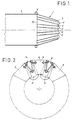
- la figure 1 représente schématiquement, en coupe, la partie arrière d'une turbomachine à gaz munie d'une tuyère à géométrie variable constituée selon la présente invention.
- la figure 2 est une vue arrière de la tuyère représentée sur la figure 1,
- la figure 3 montre la disposition des moyens d'accrochage d'un volet suiveur sur un volet commandé, les moyens de fixation desdits moyens d'accrochage n'étant pas représentés par souci de clarté,
- la figure 4 montre la fixation de l'épingle sur le volet suiveur, et
- la figure 5 montre l'articulation de l'épingle sur le volet commandé.
- Figure 1 shows schematically, in section, the rear part of a gas turbomachine provided with a variable geometry nozzle formed according to the present invention.
- FIG. 2 is a rear view of the nozzle shown in FIG. 1,
- FIG. 3 shows the arrangement of the attachment means of a follower flap on a controlled flap, the means of fixing said attachment means not being shown for the sake of clarity,
- FIG. 4 shows the attachment of the pin to the follower flap, and
- Figure 5 shows the articulation of the pin on the controlled flap.
La référence 1 représente une tuyère axisymétrique à géométrie variable qui est disposée en aval d'un tube à jet 2 de gaz chauds d'une turbomachine d'aviation.Reference 1 represents an axisymmetric nozzle with variable geometry which is arranged downstream of a
La tuyère 1 comporte une première série de volets 3, dits volets commandés, qui se présentent sous la forme de plaques trapézoïdales articulées de manière connue par leur extrémité amont 3b sur un anneau polygonal 4 solidaire du tube à jet 2.The nozzle 1 comprises a first series of
Elle comporte également une deuxième série de volets 5, dits volets suiveurs, qui sont intercalés entre les volets commandés et qui sont destinés à obturer les interstices séparant les volets commandés 3. Chaque volet suiveur 5 chevauche les surfaces intérieures des deux volets commandés 3 adjacents, et il est maintenu positivement en appui sur lesdits deux volets commandés 3 par un dispositif d'accrochage, se présentant sous la forme d'une épingle double 6 qui agit à la manière d'un ressort. Chaque volet commandé 3 est réalisé en matériau composite et il présente sur sa face extérieure une partie métallique 3a qui est articulée sur l'anneau polygonal 4, et qui est reliée aux moyens de manoeuvre de la série de volets commandés 3.It also includes a second series of
Le volet suiveur 5 est également réalisé en matériau composite. Il se présente sous la forme d'un secteur tronconique 7 qui se termine en aval par une partie sphérique 8. Le volet suiveur 5 forme ainsi un lobe convexe, à la sortie des gaz s'échappant de la tuyère 1. Le secteur tronconique 7 est solidaire d'une pièce métallique 9 dont l'extrémité amont 10 est articulée sur l'anneau polygonal 4.The
L'épingle double 6 est réalisée à partir d'un fil à ressort. Elle présente, en amont, deux portions d'extrémité 11, 12 qui, au repos, sont sensiblement alignées et dirigées dans des directions opposées et qui sont articulées respectivement sur les deux volets commandés 3 adjacents au voisinage de l'articulation 3b desdits volets commandés sur l'anneau 4. L'articulation s'effectue par engagement coulissant des portions d'extrémité 11 et 12 de l'épingle 6 dans les alésages de colliers 13 fixés par boulonnage sur la face extérieure desdits volets commandés 3.The
L'épingle 6 est fixée en amont par sa portion médiane 15 sur la face extérieure du volet suiveur 5 par des moyens de fixation 17 qui comportent des vis 18 assurant la liaison du secteur tronconique en composite 7, de la pièce métallique 9 et de la portion médiane 15 de l'épingle 6. La portion médiane 15 se présente sous la forme d'un coude emprisonné entre la pièce métallique 9 et un cavalier 19 engagé dans les vis 18. Des écrous 20 assurent le bridage de l'ensemble.The
Les deux branches 21 et 22 du coude 15 s'étendent vers l'amont et rejoignent respectivement les portions d'extrémité 11 et 12 au moyen de boucles 23 et 24.The two
La fonction ressort de l'épingle 6 et le sens de l'effort appliqué sur le volet suiveur 5 résultent de l'écart d'angle des deux portions d'extrémité 11 et 12 de l'épingle 6 entre la position montée et la position non montée.The spring function of the
Le maintien des volets suiveurs 5 par rapport aux volets commandés 3 est assuré, à l'arrêt, par la fonction ressort de l'épingle double 6.Maintaining the
L'épingle 6 assure ainsi une triple fonction pour le volet suiveur 5 :
- elle permet le maintien axial du
volet suiveur 5 par rapport à l'éjection des gaz, - elle permet le guidage latéral du
volet suiveur 5, - elle permet le maintien en contact du
volet suiveur 5 et des volets commandés adjacents 3 lors de l'arrêt du moteur.
- it allows axial maintenance of the
follower flap 5 with respect to the ejection of gases, - it allows lateral guiding of the
follower flap 5, - it keeps the
follower flap 5 and the adjacent controlledflaps 3 in contact when the engine is stopped.
Claims (4)
- Axisymmetric nozzle with adjustable cross-section intended to equip a turbine engine, and including at least one ring of flaps, the said ring of flaps comprising a series of driven flaps (3) and a series of interposed follower flaps (5), each follower flap (5) overlapping the inner surfaces of the two adjacent driven flaps (3) and being retained on the said driven flaps by fastening means, characterized in that the means of fastening a follower flap (5) include a double pin (6) performing the function of a spring for holding the said follower flap (5) against the inner surfaces of the two adjacent driven flaps (3), the said pin (6) including, upstream, two end portions (11, 12) articulated respectively onto the two adjacent driven flaps (3) and, downstream, a central portion (15) fixed onto the said follower flap (5) by fixing means (17).
- Nozzle according to Claim 1, in which the follower flaps (5) are lobed.
- Nozzle according to Claim 2, in which the follower flap (5) has the shape of a frustoconical sector (7) which terminates downstream in a spherical part (8).
- Nozzle according to any one of Claims 1 to 3, characterized in that the end portions (11, 12) of the pin (6) are divergent.
Applications Claiming Priority (2)
| Application Number | Priority Date | Filing Date | Title |
|---|---|---|---|
| FR9305060 | 1993-04-29 | ||
| FR9305060A FR2704599B1 (en) | 1993-04-29 | 1993-04-29 | VARIABLE GEOMETRY EJECTION NOZZLE FOR TURBOMACHINE. |
Publications (2)
| Publication Number | Publication Date |
|---|---|
| EP0622538A1 EP0622538A1 (en) | 1994-11-02 |
| EP0622538B1 true EP0622538B1 (en) | 1996-11-20 |
Family
ID=9446563
Family Applications (1)
| Application Number | Title | Priority Date | Filing Date |
|---|---|---|---|
| EP94400901A Expired - Lifetime EP0622538B1 (en) | 1993-04-29 | 1994-04-27 | Variable geometry exhaust nozzle for turbomachine |
Country Status (3)
| Country | Link |
|---|---|
| EP (1) | EP0622538B1 (en) |
| DE (1) | DE69400937T2 (en) |
| FR (1) | FR2704599B1 (en) |
Families Citing this family (6)
| Publication number | Priority date | Publication date | Assignee | Title |
|---|---|---|---|---|
| US6471469B2 (en) * | 2000-11-30 | 2002-10-29 | General Electric Company | Methods and apparatus for sealing gas turbine engine variable nozzles |
| FR2860046B1 (en) * | 2003-09-19 | 2005-12-02 | Snecma Moteurs | HOT PIPE CONTROL OF AXISYMETRIC TUYERE TURBOJET ENGINE |
| DE102006008346B4 (en) | 2006-02-21 | 2008-06-19 | J. Eberspächer GmbH & Co. KG | Throttle arrangement and exhaust system equipped with it |
| DE102008022271A1 (en) | 2008-05-06 | 2009-11-26 | Opara, Günther | Nozzle i.e. jet-nozzle, for e.g. gas turbine of aircraft, has one-piece tubular body including wall that forms convergent and divergent channel parts by radial contraction of cross-section dimension of nozzle |
| JP6010687B2 (en) | 2012-04-27 | 2016-10-19 | ゼネラル・エレクトリック・カンパニイ | Connection of an annular member of a gas turbine engine |
| WO2014200403A1 (en) * | 2013-06-14 | 2014-12-18 | Saab Ab | Variable-geometry exhaust nozzle for a jet engine and a method for varying the nozzle |
Family Cites Families (7)
| Publication number | Priority date | Publication date | Assignee | Title |
|---|---|---|---|---|
| US2969641A (en) * | 1955-10-17 | 1961-01-31 | Gen Electric | Aerodynamic nozzle |
| US3610533A (en) * | 1970-06-29 | 1971-10-05 | Gen Electric | Variable area and thrust-reversing nozzle |
| FR2227433B1 (en) * | 1973-04-27 | 1975-08-22 | Snecma | |
| US4502636A (en) * | 1982-04-07 | 1985-03-05 | Rolls-Royce Inc. | Variable geometry ejector nozzle for turbomachines |
| FR2557211A1 (en) * | 1983-12-21 | 1985-06-28 | Camboulives Andre | EJECTION ASSEMBLY, IN PARTICULAR FOR TURBOJET ENGINE |
| US4878618A (en) * | 1988-12-08 | 1989-11-07 | United Technologies Corporation | Wear resistant, self-damping clamp assembly |
| CN1022433C (en) * | 1989-04-11 | 1993-10-13 | 通用电气公司 | Axisymmetric vectoring exhaust nozzle seal |
-
1993
- 1993-04-29 FR FR9305060A patent/FR2704599B1/en not_active Expired - Fee Related
-
1994
- 1994-04-27 DE DE69400937T patent/DE69400937T2/en not_active Expired - Fee Related
- 1994-04-27 EP EP94400901A patent/EP0622538B1/en not_active Expired - Lifetime
Also Published As
| Publication number | Publication date |
|---|---|
| FR2704599A1 (en) | 1994-11-04 |
| EP0622538A1 (en) | 1994-11-02 |
| DE69400937D1 (en) | 1997-01-02 |
| DE69400937T2 (en) | 1997-05-28 |
| FR2704599B1 (en) | 1995-06-09 |
Similar Documents
| Publication | Publication Date | Title |
|---|---|---|
| EP0846854B1 (en) | Gas turbine thrust-reverser with doors kept flush in the nacelle surface | |
| EP1007835B1 (en) | Backblast gas structure equipped with thrust reverser with two rear doors and planar exhaust area | |
| EP0080404A1 (en) | Assembly of two joined rotationally symmetrical objects made of materials with differing co-efficients of dilatation | |
| FR2622928A1 (en) | PUSH INVERTER OF DOOR TURBOJET, WITH VARIABLE EJECTION SECTION | |
| FR2741910A1 (en) | DOOR REVERSER OF TURBOJET WITH DOORS WITH ARTICULATED REAR PANEL | |
| FR2966882A1 (en) | THRUST INVERTER FOR AIRCRAFT TURBOJET ENGINE WITH REDUCED ACTUATOR NUMBERS | |
| CA2478781A1 (en) | Convergent-divergent nozzle for jet turbine engine | |
| EP2178760B1 (en) | Jet engine nacelle intended to equip an aircraft | |
| EP0622538B1 (en) | Variable geometry exhaust nozzle for turbomachine | |
| FR2723764A1 (en) | SEALING BETWEEN FOLLOWING DIVERGENT AND CONVERGENT SHUTTERS OF A TURBOREACTOR EJECTION NOZZLE | |
| CA2879064A1 (en) | Cascade thrust reverser for an aircraft turbofan | |
| EP1517032B1 (en) | Operated flap for an axisymmetrical exhaust nozzle of a jet engine | |
| EP2188178B1 (en) | Jet engine nacelle intended to equip an aircraft | |
| FR2915550A1 (en) | VALVE VALVE FOR A COOLING SYSTEM IN A TURBOMACHINE | |
| FR3038587A1 (en) | AIRCRAFT TURBOBOREACTOR NACELLE, PROPULSIVE ASSEMBLY COMPRISING A BOAT, AND AIRCRAFT HAVING AT LEAST ONE PROPULSIVE ASSEMBLY | |
| WO1998040618A1 (en) | Bypass turbojet thrust reverser having doors with streamlined external structure | |
| EP3164588B1 (en) | Rear frame for a thrust reverser structure with diversion grids | |
| FR2937679A1 (en) | DEVICE FOR COLLECTING AIR IN A TURBOMACHINE | |
| FR2933127A1 (en) | DEVICE FOR COLLECTING AIR IN A TURBOMACHINE | |
| FR2792366A1 (en) | AXISYMMETRIC EJECTION NOZZLE, CONVERGENT DIVERGENT AND ADJUSTABLE | |
| FR2934327A1 (en) | PUSH REVERSING DEVICE | |
| EP3877640B1 (en) | Sealing joint for aircraft turbojet engine nacelle | |
| FR3070466A1 (en) | SEALING DEVICE FOR AN AIRCRAFT AIRCRAFT TANK | |
| WO2021123621A1 (en) | Thrust reverser with anti-buckling actuating system | |
| FR2929655A1 (en) | DOUBLE FLOW TURBOREACTOR NACELLE |
Legal Events
| Date | Code | Title | Description |
|---|---|---|---|
| PUAI | Public reference made under article 153(3) epc to a published international application that has entered the european phase |
Free format text: ORIGINAL CODE: 0009012 |
|
| 17P | Request for examination filed |
Effective date: 19940521 |
|
| AK | Designated contracting states |
Kind code of ref document: A1 Designated state(s): DE FR GB |
|
| GRAG | Despatch of communication of intention to grant |
Free format text: ORIGINAL CODE: EPIDOS AGRA |
|
| GRAH | Despatch of communication of intention to grant a patent |
Free format text: ORIGINAL CODE: EPIDOS IGRA |
|
| 17Q | First examination report despatched |
Effective date: 19960403 |
|
| GRAH | Despatch of communication of intention to grant a patent |
Free format text: ORIGINAL CODE: EPIDOS IGRA |
|
| GRAA | (expected) grant |
Free format text: ORIGINAL CODE: 0009210 |
|
| AK | Designated contracting states |
Kind code of ref document: B1 Designated state(s): DE FR GB |
|
| REF | Corresponds to: |
Ref document number: 69400937 Country of ref document: DE Date of ref document: 19970102 |
|
| GBT | Gb: translation of ep patent filed (gb section 77(6)(a)/1977) |
Effective date: 19961202 |
|
| PLBE | No opposition filed within time limit |
Free format text: ORIGINAL CODE: 0009261 |
|
| STAA | Information on the status of an ep patent application or granted ep patent |
Free format text: STATUS: NO OPPOSITION FILED WITHIN TIME LIMIT |
|
| 26N | No opposition filed | ||
| REG | Reference to a national code |
Ref country code: GB Ref legal event code: IF02 |
|
| REG | Reference to a national code |
Ref country code: FR Ref legal event code: TP Ref country code: FR Ref legal event code: CD |
|
| PGFP | Annual fee paid to national office [announced via postgrant information from national office to epo] |
Ref country code: FR Payment date: 20040322 Year of fee payment: 11 |
|
| PGFP | Annual fee paid to national office [announced via postgrant information from national office to epo] |
Ref country code: GB Payment date: 20040329 Year of fee payment: 11 Ref country code: DE Payment date: 20040329 Year of fee payment: 11 |
|
| PG25 | Lapsed in a contracting state [announced via postgrant information from national office to epo] |
Ref country code: GB Free format text: LAPSE BECAUSE OF NON-PAYMENT OF DUE FEES Effective date: 20050427 |
|
| PG25 | Lapsed in a contracting state [announced via postgrant information from national office to epo] |
Ref country code: DE Free format text: LAPSE BECAUSE OF NON-PAYMENT OF DUE FEES Effective date: 20051101 |
|
| GBPC | Gb: european patent ceased through non-payment of renewal fee |
Effective date: 20050427 |
|
| PG25 | Lapsed in a contracting state [announced via postgrant information from national office to epo] |
Ref country code: FR Free format text: LAPSE BECAUSE OF NON-PAYMENT OF DUE FEES Effective date: 20051230 |
|
| REG | Reference to a national code |
Ref country code: FR Ref legal event code: ST Effective date: 20051230 |