EP0622319B1 - Apparatus for stacking signatures - Google Patents
Apparatus for stacking signatures Download PDFInfo
- Publication number
- EP0622319B1 EP0622319B1 EP94103659A EP94103659A EP0622319B1 EP 0622319 B1 EP0622319 B1 EP 0622319B1 EP 94103659 A EP94103659 A EP 94103659A EP 94103659 A EP94103659 A EP 94103659A EP 0622319 B1 EP0622319 B1 EP 0622319B1
- Authority
- EP
- European Patent Office
- Prior art keywords
- support elements
- signatures
- signature support
- stack
- jogger
- Prior art date
- Legal status (The legal status is an assumption and is not a legal conclusion. Google has not performed a legal analysis and makes no representation as to the accuracy of the status listed.)
- Expired - Lifetime
Links
- 238000000429 assembly Methods 0.000 description 32
- 230000000712 assembly Effects 0.000 description 32
- 238000010276 construction Methods 0.000 description 4
- 230000000694 effects Effects 0.000 description 4
- 230000010355 oscillation Effects 0.000 description 3
- 230000015572 biosynthetic process Effects 0.000 description 2
- 238000009825 accumulation Methods 0.000 description 1
- 238000000151 deposition Methods 0.000 description 1
Images





Classifications
-
- B—PERFORMING OPERATIONS; TRANSPORTING
- B65—CONVEYING; PACKING; STORING; HANDLING THIN OR FILAMENTARY MATERIAL
- B65H—HANDLING THIN OR FILAMENTARY MATERIAL, e.g. SHEETS, WEBS, CABLES
- B65H29/00—Delivering or advancing articles from machines; Advancing articles to or into piles
- B65H29/26—Delivering or advancing articles from machines; Advancing articles to or into piles by dropping the articles
- B65H29/28—Delivering or advancing articles from machines; Advancing articles to or into piles by dropping the articles from mechanical grippers
-
- B—PERFORMING OPERATIONS; TRANSPORTING
- B65—CONVEYING; PACKING; STORING; HANDLING THIN OR FILAMENTARY MATERIAL
- B65H—HANDLING THIN OR FILAMENTARY MATERIAL, e.g. SHEETS, WEBS, CABLES
- B65H31/00—Pile receivers
- B65H31/30—Arrangements for removing completed piles
- B65H31/3009—Arrangements for removing completed piles by dropping, e.g. removing the pile support from under the pile
- B65H31/3018—Arrangements for removing completed piles by dropping, e.g. removing the pile support from under the pile from opposite part-support elements, e.g. operated simultaneously
-
- B—PERFORMING OPERATIONS; TRANSPORTING
- B65—CONVEYING; PACKING; STORING; HANDLING THIN OR FILAMENTARY MATERIAL
- B65H—HANDLING THIN OR FILAMENTARY MATERIAL, e.g. SHEETS, WEBS, CABLES
- B65H31/00—Pile receivers
- B65H31/34—Apparatus for squaring-up piled articles
- B65H31/38—Apparatus for vibrating or knocking the pile during piling
-
- B—PERFORMING OPERATIONS; TRANSPORTING
- B65—CONVEYING; PACKING; STORING; HANDLING THIN OR FILAMENTARY MATERIAL
- B65H—HANDLING THIN OR FILAMENTARY MATERIAL, e.g. SHEETS, WEBS, CABLES
- B65H2301/00—Handling processes for sheets or webs
- B65H2301/40—Type of handling process
- B65H2301/42—Piling, depiling, handling piles
- B65H2301/421—Forming a pile
- B65H2301/4211—Forming a pile of articles alternatively overturned, or swivelled from a certain angle
- B65H2301/42112—Forming a pile of articles alternatively overturned, or swivelled from a certain angle swivelled from 180°
-
- B—PERFORMING OPERATIONS; TRANSPORTING
- B65—CONVEYING; PACKING; STORING; HANDLING THIN OR FILAMENTARY MATERIAL
- B65H—HANDLING THIN OR FILAMENTARY MATERIAL, e.g. SHEETS, WEBS, CABLES
- B65H2301/00—Handling processes for sheets or webs
- B65H2301/40—Type of handling process
- B65H2301/42—Piling, depiling, handling piles
- B65H2301/422—Handling piles, sets or stacks of articles
- B65H2301/4226—Delivering, advancing piles
- B65H2301/42261—Delivering, advancing piles by dropping
- B65H2301/422615—Delivering, advancing piles by dropping from opposite part-support elements, e.g. operated simultaneously
-
- B—PERFORMING OPERATIONS; TRANSPORTING
- B65—CONVEYING; PACKING; STORING; HANDLING THIN OR FILAMENTARY MATERIAL
- B65H—HANDLING THIN OR FILAMENTARY MATERIAL, e.g. SHEETS, WEBS, CABLES
- B65H2301/00—Handling processes for sheets or webs
- B65H2301/40—Type of handling process
- B65H2301/44—Moving, forwarding, guiding material
- B65H2301/446—Assisting moving, forwarding or guiding of material
- B65H2301/4462—Assisting moving, forwarding or guiding of material by jogging
-
- B—PERFORMING OPERATIONS; TRANSPORTING
- B65—CONVEYING; PACKING; STORING; HANDLING THIN OR FILAMENTARY MATERIAL
- B65H—HANDLING THIN OR FILAMENTARY MATERIAL, e.g. SHEETS, WEBS, CABLES
- B65H2402/00—Constructional details of the handling apparatus
- B65H2402/30—Supports; Subassemblies; Mountings thereof
- B65H2402/35—Supports; Subassemblies; Mountings thereof rotating around an axis
- B65H2402/351—Turntables
Definitions
- the invention relates to an apparatus for use in stacking signatures according to the preamble of claim 1.
- An apparatus which receives signatures, forms intermediate stacks of signatures and deposits the intermediate stacks of signatures on a main stack of signatures is disclosed in U.S. Patent No. 4,068,567, issued January 17, 1978 and entitled "Combined Ejector-Gate Means for Rotatable Table of an Article Counter-Stacker".
- the apparatus disclosed in this patent includes a stacker section which receives newspapers. The newspapers are stacked on cooperating pairs of upwardly angled blades carried on endless chains.
- a stack supporting table is disposed beneath the stacker section and receives stacks of signatures from the stacker section. The table is rotatable to offset relatively thick folded edge portions of the signatures received from the stacker section.
- Apparatus for use in forming stacks of signatures is also disclosed in U.S. Patent Nos. 3,532,230; 3,599,807; 4,183,704; and 4,678,387.
- GB-A-2 063 224 discloses an apparatus for stacking sheet material according to the preamble of Claim 1.
- This apparatus comprises first and second pluralities of longitudinally extending signature support elements. Further, it comprises first drive means for moving the first plurality of signature support elements along a first circuitous path, and second drive means for moving the second plurality of signature supports elements along a second circuitous path. The second circuitous path is separate from the first circuitous path.
- Each signature support element has surface means for engaging a lower side of a stack of signatures to support the stack of signatures.
- the apparatus further includes jogger means for jogging a stack of signatures supported by one of the signature support elements of the first plurality of signature support elements and one of the signature support elements of the second plurality of signature support elements.
- the jogger means includes a first jogger plate engageable with a first end portion of a stack of signatures, a second jogger plate engageable with a second end portion of the stack of signatures, and means for moving the first and second jogger plates relative to the stack of signatures.
- the first circuitous path extends around the first jogger plate and the second circuitous path extends around the second jogger plate.
- FIG. 1 An apparatus 10 for use in stacking signatures is illustrated schematically in Fig. 1.
- the apparatus 10 receives signatures 12 (Fig. 2) from an infeed conveyor 14 in a stream 16.
- the signatures 12 are conducted in the stream 16 with folded edge portions of the signatures leading and open edge portions of the signatures trailing.
- the signatures 12 are formed into an intermediate stack 18 in a stacker assembly 20.
- a jogger assembly 24 (Figs. 1 and 5A) is operable to jog the intermediate stack 18 (Fig. 2) of signatures to align opposite edge portions of the signatures in the intermediate stack of signatures.
- the jogger assembly 24 (Fig. 1) is continuously operated to align the edge portions of the signatures.
- the intermediate stack of signatures is deposited onto a receiving platform, which, in the illustrated embodiment of the invention, is a turntable 26 (Figs. 2 and 3).
- the receiving platform is the turntable 26
- the intermediate stack 18 of signatures is received on a main stack 28 of signatures on the turntable 26.
- the turntable 26 rotates the main stack 28 through one-half of a revolution.
- the relatively thick folded edge portions of the signatures in the intermediate stacks are offset from each other.
- the main stack 28 of signatures as being composed of layers of signatures having folded edge portions in one layer of signatures offset by 180° from the folded edge portions of the next succeeding layer of signatures. Therefore, the upper side of the main stack 28 of signatures is generally horizontal so that the main stack of signatures is relatively stable.
- a suitable conveyor assembly (not shown) is provided to sequentially move main stacks 28 of signatures from the turntable 26.
- the main stack is removed from the turntable 26 for further processing.
- a main stack 28 of signatures can be completely removed from the turntable 26 in substantially less time then is required to form an intermediate stack 18 of signatures. It is contemplated that it may be desired to eliminate the accumulation of intermediate stacks 18 on the turntable 26 and the formation of a relatively large main stack 28. If this is the case, the turntable 26 may be replaced by a stationary platform.
- the conveyor assembly would be operated to move each intermediate stack 18 off of the platform in turn before the next succeeding intermediate stack is received on the platform.
- the infeed conveyor 14 (Fig. 2) feeds signatures 12 to the stacker assembly 20 in a stream 16 with folded edge portions of the signatures leading.
- the signatures 12 are supported in the stacker assembly 20 until sufficient signatures have accumulated to form an intermediate stack 18 of a desired size.
- a completed intermediate stack 18 of signatures is then transferred from the stacker assembly 20 to the turntable 26 and a next succeeding intermediate stack of signatures started without interrupting the stream 16 of signatures.
- the stacker assembly 20 includes a first plurality 32 (Fig. 1) of longitudinally extending signature support elements 34, hereinafter referred to as slats.
- the stacker assembly 20 also includes a second plurality 36 of slats 34.
- Each of the slats 34 of the first plurality 32 of slats is moved along a circuitous path by a first drive assembly 38.
- Each of the slats 34 of the second plurality 36 of slats is moved along a circuitous path by a second drive assembly 40.
- the first drive assembly 38 moves each of the slats 34 in the first plurality 32 of slats along a first circuitous path, which has been indicated at 44 in Fig. 1.
- the first circuitous path 44 has a vertical left or outer run 46 along which the slats 34 of the first plurality 32 of slats move vertically upwardly.
- the circuitous path 44 has a vertical right or inner run 48 along which the slats 34 of the first plurality 32 of slots move vertically downwardly.
- a lower semi-circular connector portion 52 interconnects the lower ends of the outer and inner runs 46 and 48 of the circuitous path 44.
- a semi-circular upper section 54 interconnects the upper ends of the outer and inner runs 46 and 48.
- the first drive assembly 38 is operable to intermittently move the slats 34 in a clockwise direction (as viewed in Fig. 1) along the circuitous path 44 between a loading position, indicated at 58 in Figs. 1 and 3, an intermediate position indicated at 60 in Figs. 1 and 3, and a standby position indicated at 62 in Figs. 1 and 3.
- the first drive assembly 38 is operable to quickly index the slats 34 between loading position 58, intermediate position 60 and standby position 62.
- the longitudinal central axes of the slats 34 are maintained horizontal and parallel to each other at all times during movement of the slats along the first circuitous path 44 (Fig. 1).
- a flat front side surface 66 on the slat 34 is horizontal and faces upwardly.
- the flat front side surface 66 of the slat is also horizontal.
- the front side surface 66 of the slat 34 faces downwardly (see Figs. 1 and 3).
- the flat front side surface 66 on the slat 34 is sloped at an angle of approximately 45° to a horizontal plane (Fig. 3).
- the first drive assembly 38 includes a pair of flexible drive elements or chains 74 and 76 (Figs. 2 and 5A).
- the chains 74 and 76 move along a circuitous path which is of the same size and orientation as the circuitous path 44 and which is coextensive with a portion of the circuitous path 44. It should be understood that although chains 74 and 76 have been used in the first drive assembly 38, it is contemplated that the chains 74 and 76 could be replaced by a single relatively wide belt if desired. Of course, a pair of belts could also be used if desired.
- the chains 74 and 76 extend around upper and lower sprocket wheel assemblies 80 and 82 (Figs. 4 and 5A).
- the upper sprocket wheel assembly 80 includes a pair of sprockets 86 and 88 (Fig. 4) which are interconnected by a cylindrical hub 90.
- the lower sprocket wheel assembly 82 has the same construction as the upper sprocket wheel assembly 80.
- the sprocket wheel assemblies 80 and 82 are rotatable about horizonal axes which are disposed in a vertical plane.
- the inner end portions 72 of the slats 34 are fixedly connected to the chains 74 and 76 (Figs. 2).
- the chains 74 and 76 support the slats 34 in a cantilevered relationship.
- the slats 34 extend horizontally outwardly from the chains 74 and 76 to free end portions.
- the chains 74 and 76 move along the circuitous path 44 to move the inner end portions 72 of the slats 34 along the circuitous path.
- the slats 34 in the second plurality 36 of slats are moved along a continuous circuitous path indicated schematically at 94 in Fig. 1.
- the continuous circuitous path 94 has the same configuration and orientation as the continuous circuitous path 44.
- the slats 34 are moved along the continuous circuitous path 94 in a counterclockwise direction between a loading position 98, an intermediate position 100 and a standby position 102 (Figs. 1 and 3). These positions correspond to and are horizontally aligned with the loading position 58, intermediate position 60 and standby position 62 for the first plurality 32 of slats 34.
- the longitudinal axes of the slats 34 are maintained horizontal and parallel to the longitudinal axes of the slats 34 in the first plurality 32 of slats.
- a flat front side surface 66 (Figs. 1 and 3) of the slat is horizontal and faces upwardly.
- the front surface 66 is still horizontal. However, at this time, the front surface 66 faces downwardly.
- the surface 66 slopes at an angle of approximately 45° to a horizontal plane.
- a slat 34 which is at the loading position 58 has a horizontal front side surface 66 which is disposed in the same plane as the horizontal front side surface of a slat at the loading position 98 (Fig. 3).
- the slats 34 at the loading positions 58 and 98 are spaced apart by a horizontal distance which is less than the length of a folded edge portion of a signature 12.
- the signatures 12 are fed into the stacker assembly 20 at a location which is above the slats 34 at the loading positions 58 and 98 (Figs. 2 and 3). Therefore, the signatures are supported on the upwardly facing coplanar front side surfaces 66 of the slats 34 at the loading positions 58 and 98 (Fig. 3).
- the first and second drive assemblies 38 and 40 are operated to quickly index the slats 34 along the circuitous paths 44 and 94 (Fig. 1).
- the slats 34 move downwardly from the loading positions 58 and 98, they are moved away from each other and rotated to deposit an intermediate stack 18 on the main stack 28 of signatures on the turntable 26.
- the vertical outer runs of the circuitous paths 44 and 94 are spaced apart by a horizontal distance which is greater than the length of the folded edge portions of the signatures 12 (Figs. 1, 2 and 3).
- the second drive assembly 40 has the same construction as the first drive assembly 38 and is connected with the slats 34 of the second plurality 36 of slats in the same manner as in which the first drive assembly 38 is connected with the slats of the first plurality 32 of slats.
- the second drive assembly 40 includes a pair of chains 110 and 112 (Fig. 5A) corresponding to the chains 74 and 76 in the first drive assembly 38.
- the chains 110 and 112 along a circuitous path which is of the same size and orientation as the circuitous path 94 and which is coextensive with a portion of the circuitous path 94.
- the chains 110 and 112 in the second drive assembly 40 extend around upper and lower sprocket wheel assemblies 116 and 118.
- the sprocket wheel assemblies 116 and 118 are rotatable about horizontal axes.
- the horizontal axes about which the sprocket wheel assemblies 116 and 118 rotate are disposed in a vertical plane which is parallel to a vertical plane containing horizontal axes about which the upper and lower sprocket wheel assemblies 80 and 82 of the first drive assembly 38 are rotatable.
- the end portions 72 of the slats 34 of the second plurality 36 of slats are connected with the chains 110 and 112 in the same manner as previously described for the slats of the first plurality 32 of slats.
- the slats 34 of the second plurality 36 of slats are supported in a cantilevered relationship from the chains 110 and 112 with their longitudinal central axes horizontal and parallel to each other.
- the longitudinal axes of the slats 34 in the second plurality 36 of slats are maintained in a parallel relationship with the horizontal longitudinal axes of the slats in the first plurality 32 of slats and with the horizontal axes about which the sprocket wheel assemblies 80, 82, 116 and 118 rotate during movement of the slats along the circuitous paths 44 and 94 (Fig 1).
- the slats 34 in the first plurality 32 of slats and drive chains 74 and 76 move in a clockwise direction (as viewed in Fig. 1) around the circuitous path 46.
- the slats 34 in the second plurality 36 of slats and drive chains 110 and 112 move in a counterclockwise direction (as viewed in Fig. 1) around the circuitous path 94. Movement of the slats 34 in the first plurality 32 of slats is coordinated with the movement of the slats in the second plurality 36 of slats.
- the slats 34 in the first and second pluralities 32 and 36 of slats simultaneously move downward toward the loading positions 58 and 98 with the front side surfaces 66 of the slats horizontal and disposed in the same plane. This enables a slat 34 in the first plurality 32 of slats and a slat 34 in the second plurality 36 of slats to cooperate with each other to lower signatures as the two slats move downwardly to their respective loading positions 58 and 98.
- the slats are stationary and cooperate with each other to support the signatures while an intermediate stack 18 of signatures 12 of a desired size is accumulated on the two slats.
- the drive assemblies 38 and 40 for the first and second pluralities 32 and 36 of slats 34 are disposed on one side of a vertical plane 124 (Figs. 2 and 7).
- the drive chains 74 and 110 (Fig. 5A) are disposed in a plane which is parallel to the plane 124 (Fig. 2).
- the drive chains 76 and 112 are also disposed in a plane which is parallel to the plane 124.
- the circuitous paths 44 and 94 (Fig. 1) are parallel to the plane 124 (Figs. 2 and 7).
- the slats 34 of the first and second pluralities 32 and 36 of slats have longitudinal axes which are maintained perpendicular to the vertical plane 124 throughout movement of the slats along the circuitous paths 44 and 94 (Fig. 1). Therefore, a front side surface 66 on each of the slates 34 is perpendicular to the plane 124 (Figs. 2 and 7) throughout movement of the slats along the circuitous paths 44 and 94.
- the front side surfaces 66 on the slats 34 are disposed on a side of the vertical plane 124 opposite from the drive assemblies 38 and 40 (Fig. 7) throughout movement of the slats 34 along the circuitous paths 44 and 94.
- the mounting sections 72 of the slats 34 extend through the vertical plane 124 and are connected with first and second drive assemblies 38 and 40.
- the slats 34 support an intermediate stack 18 of signatures (Fig. 2) on a side of the vertical plane 124 opposite from the side on which the drive assemblies 38 and 40 are located.
- an intermediate stack 18 of signatures supported by the slats 34 is entirely disposed on the right (as viewed in Fig. 2) side of the vertical plane 124.
- the first and second drive assemblies 38 and 40 (Figs. 2 and 7) are entirely disposed on the left (as viewed in Fig. 2) side of the vertical plane 124.
- the vertical plane 124 extends parallel to the circuitous paths 44 and 94 along which the slats 34 are moved.
- the sprocket assemblies 80, 82, 116 and 118 (Figs. 5 and 6) of the drive assemblies 38 and 40 are rotatable about horizontal axes which extend parallel to each other and perpendicular to the vertical plane 124 (Figs. 2 and 7).
- the horizontal axes about which the sprocket wheel assemblies 80, 82, 116 and 118 are rotatable are disposed in two parallel vertical planes which extend perpendicular to the vertical plane 124.
- the horizontal longitudinal axes of the slats 34 are maintained parallel to the planes containing the axes of rotation of the sprocket wheel assemblies 80, 82, 116 and 118.
- An intermediate stack 18 of signatures extends through the parallel vertical planes containing the axes of rotation of the sprocket wheel assemblies 80, 82, 116 and 118.
- a main drive system 128 (Figs. 1, 2 and 3) is connected with the drive assemblies 38 and 40.
- the main drive system 128 includes a main drive motor 130 (Fig. 1) which is connected with the drive assemblies 38 and 40 through a single revolution clutch 132.
- the single revolution clutch 132 (Figs. 2 and 3) drives a main drive belt 134.
- the drive belt 134 is intermittently driven to operate the drive assemblies 38 and 40.
- Operation of the drive assemblies 38 and 40 simultaneously indexes the slats 34 in the first plurality 32 of slats and the slats in the second plurality of slats 36 between the loading positions 58 and 98, intermediate positions 60 and 100 and standby positions 62 and 102 (Fig. 3).
- the slats 34 are indexed by the drive assemblies 38 and 40 along the circuitous paths 44 and 94 (Fig. 1).
- the slats 34 are then stopped while an intermediate stack 18 (Fig. 3) of signatures accumulates on a pair of slats 34 disposed at the loading positions 58 and 98.
- the single revolution clutch 132 effects operation of the drive assemblies 38 and 40 to again index the slats 34.
- the slats 34 can be readily moved into the stream 16 (Fig. 2) of signatures 12 from the infeed conveyor 14 with minimum disturbance. This is because the slats 34 are of a relatively small width as measured on the front side surfaces 66 and perpendicular to the longitudinal central axes of the slats.
- single revolution clutch 132 was obtained from Warner Electric and was a Super CB-6 wrap spring clutch. Warner Electric has a pace of business at Beloit, Illinois. It should also be understood that an intermittent drive mechanism other than a single revolution clutch could be used if desired.
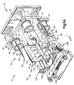
- the jogger assembly 24 (Figs. 5A, 5B, 6 and 7) cooperates with the stacker assembly 20 to jog an intermediate stack 18 of signatures while the intermediate stack of signatures is supported by slats 34.
- the jogger assembly 24 includes a pair of side plates 142 and 144 (Figs. 5A and 5B).
- the side plate 142 extends into the central portion of the circuitous path 44 (Fig. 1).
- the side plate 144 extends into the central portion of the circuitous path 94.
- the slats 34 in the first plurality 32 of slats are moved around the side plate 142 along the continuous circuitous path 44 by the first drive assembly 38.
- the slats 34 in the second plurality 36 of slats are moved around the side plate 144 along the continuous circuitous path 94 by the second drive assembly 40.
- the loading positions 58 and 98 (Fig. 3) and the vertical inner runs of the circuitous paths 44 and 94 (Fig. 1) are disposed between the side plates 142 and 144.
- the side plate 142 of the jogger assembly 24 includes a vertical side section 148 (Fig. 5B).
- the side section 148 extends parallel to the longitudinal axes of the slats 34 of the first plurality 32 of slats and perpendicular to the vertical plane 124 (Fig. 7). Although the side section 148 of the jogger side plate 142 extends perpendicular to the vertical plane 124, the jogger side plate 142 does not extend through the vertical plane 124.
- the side section 148 of the jogger side plate 142 (Fig. 5B) has a flat vertical side surface 152 which extends perpendicular to the vertical plane 124 (Fig. 7) and parallel to the longitudinal axes of the slats 34 of the first plurality 32 of slats.
- the side surface 152 of the jogger side plate 142 is engageable with one end of an intermediate stack 18 of signatures supported in the stacker assembly 20.
- the side surface 152 is reciprocated toward and away from the end of the intermediate stack 18 of signatures to jog the end portions of the signatures into alignment with each other.
- a vertical end section 156 (Fig. 5B) of the jogger side plate 142 extends perpendicular to the side section 148 and parallel to the vertical plane 124 (Fig. 7).
- the end section 156 of the side plate 142 has a flat vertical side surface 158 which extends parallel to the vertical plane 124 and is engageable with a side of the intermediate stack 18 of signatures.
- the side surface 158 on the end section 156 engages the side of the intermediate stack 18 of signatures.
- the side surface 158 is reciprocated toward and away from the side of the intermediate stack 18 of signatures to jog the folded edge portions of the signatures into alignment with each other.
- the side plate 144 (Fig. 5B) of the jogger assembly 24 has a construction which is similar to the construction of the side plate 142.
- the side plate 144 includes a side section 168 having a flat vertical side surface 172 (Fig. 7) which extends perpendicular to the vertical plane 124.
- the side surface 172 on the side section 168 extends parallel to the side surface 152 on the side section 148 of the jogger side plate 142.
- the side surface 172 on the side section 168 of the jogger side plate 144 is parallel to the longitudinal axes of the slats 34 in the second group 36 of slots throughout movement of the slats along the circuitous path 94 (Fig. 1).
- the vertical portions of the circuitous paths 44 and 94 along which the slats 34 move downwardly are disposed between the jogger side plates 142 and 144.
- An end section 176 on the jogger side plate 144 extends perpendicular to the side section 168 and is parallel to the vertical plane 124.
- the end section 176 has a vertical side surface 178 disposed in the same plane as the vertical side surface 158 on the end section 156 of the side plate 142.
- the end sections 156 and 176 on the jogger side plates 142 and 144 are disposed on a side of the vertical plane 124 (Fig. 7) opposite from the drive assemblies 38 and 40.
- the side surface 178 is reciprocated toward and away from the side of the intermediate stack 18 of signatures to jog the folded edge portions the signatures into alignment with each other.
- the flat side surface 172 (Fig. 7) on the side section 168 is engageable with an end of an intermediate stack 18 opposite from the end which is engaged by the side surface 152 on the side section 148 of the side plate 142.
- the side surface 178 disposed on the end section 176 of the side plate 144 is engageable with the side surface of the intermediate stack 18 of signatures which is the same as the side surface of the intermediate stack which is engaged by the side surface 158 on the end section 156.
- the folded edge portions of the signatures 12 are engaged by the end sections 156 and 176.
- the jogger assembly 24 has a pair of back plates 184 and 186 (Figs. 5A and 7).
- the back plates 184 and 186 are disposed outwardly from free end portions of the cantilevered slats 34 (Figs. 6 and 7) disposed at the loading positions 58 and 98.
- the back plate 184 has an end section 188 with a flat vertical side surface 190 (Fig. 7) which extends parallel to the flat side surface 158 on the end section 156 of the side plate 142 and parallel to the vertical plane 124.
- the side surface 190 on the end section 188 of the back jogger plate 184 is engageable with a side of an intermediate stack 18 of signatures supported by the stacker assembly 20.
- the side surface 190 on the jogger back plate 124 is reciprocated toward and away from the side of the intermediate stack 18 opposite from the folded edge portions of the signatures 12 to jog the open edge portions of the signatures into alignment with each other.
- the jogger back plate 186 has an end section 194 with a vertical side surface 196.
- the side surface 196 on the end section 194 of the jogger plate 186 is disposed in the same vertical plane as the side surface 190 on the end section 188 of the jogger back plate 184.
- the side surface 196 is engageable with the same side of an intermediate stack 18 of signatures as is the side surface 190.
- the side surface 196 on the jogger back plate 186 is reciprocated toward and away from the side of the intermediate stack 18 opposite from the folded edge portions of the signatures 12 to jog the open edge portions of the signatures into alignment.
- the side surfaces 190 and 196 on the jogger back plates 184 and 186 are engageable with a side of an intermediate stack 18 opposite from a side engaged by the side surfaces 158 and 178 on the jogger side plates 148 and 168.
- the side surface 196 on the jogger back plate 186 extends parallel to the side surface 178 on the end section 176 of the jogger side plate 144 and to the vertical plane 124.
- the side surfaces 190 and 196 on the jogger back plates 184 and 186 are disposed in a vertical plane which is perpendicular to the longitudinal axes of the slats 34 in the loader assembly 20 and parallel to the vertical plane 124.
- a pair of eccentric drive assemblies 202 and 204 are provided to oscillate the jogger plates 142, 144, 184 and 186.
- the eccentric drive assemblies 202 and 204 include a plurality of drive disks 208, 210, 212 and 214 (Fig. 5B).
- the drive disks 208, 210, 212 and 214 are connected to the jogger plates 142, 144, 184 and 186.
- the drive disks 208, 210, 212 and 214 are oscillated about vertical axes which are offset from their central axes. Oscillation of the drive disks 208, 210, 212 and 214 effects movement of the side sections 148 and 168 (Fig. 5B of the jogger side plates 142 and 144 toward and away from opposite ends of an intermediate stack of signatures supported by the stacker assembly 20. In addition, oscillation of the drive disks 208, 210, 212, and 214 effects movement of the end sections 156 and 176 of the jogger side plates 142 and 144 toward and away from the side of the intermediate stack 18 which extends between the opposite ends of the stack.
- the jogger side plates 142 and 144 are reciprocated toward and away from the vertical plane 124 (Fig. 7).
- the jogger side plates 142 and 144 are also reciprocated toward and away from each other. This enables the jogger side plates 142 and 144 to align signature edges at opposite ends of an intermediate stack and along one side of an intermediate stack closest to the vertical plane 124.
- the jogger back plates 184 and 186 cooperate with the side plates 142 and 144 to align edges of signatures on opposite sides of an intermediate stack of signatures supported in the stacker assembly 20.
- a stack length adjustment screw 220 (Fig. 5A) having opposite hand threads is rotatable to adjust the distance between the jogger side plates 142 and 144 to accommodate stacks of different lengths.
- a stack width adjustment 222 is operable to actuate the eccentric drive assemblies 202 and 204 to adjust the eccentricity of the disks 208, 210, 212 and 214. Adjusting the eccentricity of the disks 208, 210, 212, and 214 adjusts the distance between the end sections 188 and 194 on the back plates 184 and 186 and the end sections 156 and 176 on the side plates 142 and 144. This enables stacks of different widths to be accommodated between the end sections 188 and 194 on the jogger back plates 184 and 186 and the end sections 156 and 176 on the jogger side plates 142 and 144.
- a drive assembly 226 (Fig. 5A) for the eccentric drive assemblies 202 and 204 is driven by a suitable motor (not shown) to effect oscillation of the disks 208, 210, 212 and 214 to oscillate the jogger plates 142, 144, 184 and 186 to jog an intermediate stack 18 of signatures while the signatures are supported by the stacker assembly 20.
- the drive assembly 226 and the eccentric drives 202 and 204 are located outwardly from the free ends of the cantilevered slats 34.
- the entire jogger assembly 24 is disposed on a side of the vertical plane 124 (Fig. 7) which is opposite from the first and second drive assemblies 38 and 40.
- the turntable 26 is disposed beneath the slats 34 of the stacker assembly 20 and the jogger plates 142, 144, 184 and 186 of the jogger assembly 24.
- the turntable 26 receives intermediate stacks 18 (Fig. 2) from the stacker assembly 20.
- the turntable 26 rotates a main stack 28 through one-half of a revolution to offset the folded edges of an intermediate stack 18 from the folded edges of the next succeeding intermediate stack. This results in the main stack being relatively level and stable.
- the turntable 26 has a rotatable circular platform 234 (Fig. 2).
- a plurality of upstanding side walls 236 and 238 (Fig. 3) are disposed on the platform 234.
- the side walls 236 and 238 engage a main stack 28 of signatures to hold the stack in position on the platform 234 during rotation of the platform.
- a drive assembly 242 is (Fig. 8) connected to a central portion of the platform 234 (Figs. 2 and 3).
- the drive assembly 242 is operable to rotate the platform 234 about a vertical axis which extends through the center of an intermediate stack 18 supported in the stacker assembly 20.
- the platform 234 is rotatable about a vertical central axis 244 (Figs. 2 and 3) which extends through the center of the main stack 28 and through the center of the intermediate stack 18 supported by the stacker assembly 20 above the turntable 26.
- the vertical central axis 244 of the circular turntable platform 234 is disposed midway between the circuitous paths 44 and 94 and midway between a pair of slats 34 disposed at the loading positions 58 and 98 (Fig. 3).
- the central axis 244 of the turntable 26 extends parallel to the side surfaces 152 and 172 (Fig. 7) on the side sections 148 and 168 of the jogger side plates 142 and 144.
- the central axis 244 of the turntable is disposed midway between the side surfaces 152 and 172 on the jogger side plates 142 and 144.
- central axis 244 of the turntable 26 extends parallel to and is disposed midway between the side surfaces on the end sections 156 and 176 of the jogger side plates 142 and 144 (Fig. 7) and the side surfaces 190 and 196 on the jogger back plates 184 and 186.
- the platform 234 has a flat circular upwardly facing side surface 248 which is disposed in a horizontal plane and extends parallel to the longitudinal axes of the slats 34 in the stacker assembly 20 (Fig. 2).
- the flat upper side surface 248 of the turntable 26 supports the main stack 28 of signatures for rotation about the central axis 244 of the turntable.
- the drive assembly 242 is operable to rotate the turntable 26 about the central axis 244 to offset the folded edge portions of succeeding intermediate stacks 18 of signatures deposited on the main stack 28 of signatures on the turntable 26. To offset the folded edge portions of the intermediate stacks 18 of signatures relative to the main stack 28, the drive assembly 242 is operable to rotate the platform 234 through 180° immediately after one intermediate stack 18 of signatures is deposited on the turntable 26 and before the next succeeding intermediate stack is deposited on the turntable.
- the drive assembly 242 (Fig. 8) could be constructed in such a manner as to sequentially rotate the turntable through 180° increments in the same direction, the drive assembly is constructed so as to sequentially rotate the turntable through 180° increments in opposite directions.
- the drive assembly 242 rotates the platform 234 in a clockwise direction (as viewed in Fig. 4) through 180° before one intermediate stack 18 of signatures is deposited on the platform.
- the drive assembly 242 then rotates the platform 234 through 180° in a counterclockwise direction (as viewed in Fig. 4) before the next succeeding intermediate stack 18 of signatures is deposited on the platform.
- the turntable drive assembly 242 includes a cylindrical drive post 254 (Fig. 8) having a central axis which is coincident with the central axis 244 of the turntable 26.
- the drive post 254 is fixedly secured to the bottom of the platform 234.
- a helical cam groove 256 is formed in the drive post 254 and extends for 180° about the circumference of the drive post.
- the cam groove 256 has a central axis which is also coincident with the central axis 244 of the drive assembly 242.
- a cylindrical cam follower 260 is mounted on a carriage 262 and extends into the helical cam groove 256.
- a plurality of guide rollers 264 on the carriage 262 engage linear vertical edge portions 266 and 268 on a pair of vertical guide bars 272 and 274 to guide movement of the carriage along the drive post 254.
- a piston and cylinder type motor 278 is connected with the carriage 262 and is operable to reciprocate the carriage 262 along the guide bars 272 and 274.
- the carriage 262 is moved vertically upwardly along a linear path from the lowered position of Fig. 8 upon operation of the motor 278.
- the cam follower 260 cooperates with the helical cam groove 256 to rotate the drive post 254 through 180° about the central axis 244.
- the direction of operation of the motor 278 is reversed to move the carriage 262 and cam follower 260 downwardly along the drive post 254.
- the cooperation between the cam follower 260 and the helical cam groove 256 results in the drive post being rotated through 180° in the opposite direction.
- a plurality of rollers 282 cooperate with an annular groove 284 formed in the upper end portion of the drive post 254 to hold the drive post against axial movement.
- a plurality of rollers 286 cooperate with an annular groove 288 formed in the lower end portion of the drive post 254 to hold the drive post against axial movement.
- the drive post 254 is rotated by cooperation between a cam follower 260 and a helical groove 256 formed in the drive post.
- a helical cam track could be provided on the outside of the drive post 254 and engaged by a suitable cam follower.
- the helical cam groove 256 extends for 180° about the circumference of the drive post 254. It is contemplated that the cam groove 256 could be constructed in such a manner as to extend through 360° about the cam post 254. If this was done, the motor 278 would be operated to move the cam follower 260 along half of the length of the cam groove in order to rotate the drive post through 180° each time an intermediate stack 18 of signatures is deposited on the turntable 26.
- the turntable may be replaced by a stationary platform or the turntable drive assembly 242 may be temporarily rendered inactive.
- the infeed conveyor 14 (Fig. 2) conducts a continuous stream 16 of signatures 12 to the stacker assembly 20 with folded edge portions of the signatures leading.
- the folded edge portions of the signatures impact against the end sections 156 and 176 (Figs. 5B and 7) on the jogger side plates 142 and 144.
- Opposite ends of the signatures 12 are engaged by the side surfaces 152 and 172 on the jogger side plates 142 and 144. This aligns the incoming signatures 12 with a partially formed intermediate stack 18 (Fig. 2) of signatures supported on a pair of slats 34 at the loading positions 58 and 98 (Fig. 3).
- the signatures 12 then move downwardly toward the upper end of the partially formed intermediate stack 18. As the signatures 12 move downwardly, the open trailing edge portions of the signatures engage the end sections 188 and 194 (Fig. 7) on the jogger back plates 184 and 186. The end sections 188 and 194 on the back plates 184 and 186 cause the signatures to move into firm abutting engagement with the end sections 156 and 176 on the jogger side plates 142 and 144.
- the turntable drive assembly 242 rotates the turntable platform 234 through 180°.
- the motor 278 (Fig. 8) is operated to raise the carriage 262 from the lower end of the drive post 254 to the upper end of the drive post. This rotates the turntable platform 234 through 180° in a counterclockwise direction (as viewed in Fig. 1).
- Rotation of the turntable platform 234 results in the folded edge portions of the immediately preceding intermediate stack 18 of signatures being moved from a position disposed to the left (as viewed in Fig. 2) of the central axis 244 of the turntable 26 to a position to the right of the turntable axis.
- the folded edge portions of the uppermost intermediate stack 18 of signatures on the main stack 28 are moved from a position directly beneath the folded edge portions of the intermediate stack 18 being accumulated in the stacker assembly 20 to a position to the right (as viewed in Fig. 2) of the axis 244 and immediately beneath the open edge portions of the signatures being accumulated in the intermediate stack 18 in the stacker assembly 20.
- the side sections 148 and 168 (Figs. 5B and 7) of the jogger side plates 142 and 144 are continuously impacted against opposite ends of the immediate stack 18 of signatures by the eccentric drive assemblies 202 and 204.
- the end sections 156 and 176 on the jogger side plates 142 and 144 are continuously impacted against the folded edges of the signatures 12 on one side of the intermediate stack 18.
- the end sections 188 and 194 of the jogger back plates 184 and 186 are continuously impacted against the open edges of the signatures 12 on an opposite side of the intermediate stack 18.
- the single revolution clutch 132 in the main drive system 128 is engaged.
- the main drive system 128 then operates the drive assembly 38 to index the slats 34 of the first plurality 32 of slats in a clockwise direction along the first circuitous path 44 (Fig. 1).
- the main drive system 128 operates the drive assembly 40 to index the slats 34 in the second plurality 36 of slats in a counterclockwise direction along the second circuitous path 94.
- the jogger assembly 24 continuously jogs the ends and sides of the intermediate stack to maintain the signatures 12 in alignment with each other.
- the jogger assembly 24 functions to promote alignment of the signatures 12 from the time the signatures are fed into the upper portion of the stacker assembly 20, through the formation of an intermediate stack 18, and through at least a portion of the depositing of the intermediate stack on the turntable 26.
- the main drive system 128 is operable to quickly move the slats 34 downwardly from their standby positions 62 and 102 to a position in which the front surfaces 66 of the slats are immediately beneath the standby positions 62 and 102 and are disposed in a common horizontal plane. Since the slats 34 are relatively long and narrow, the slats can easily move into the stream 16 of signatures with minimal interference.
- the slats 34 are quickly moved to the loading positions 58 and 98 with their upwardly facing front side surfaces 66 disposed in a common horizontal plane.
- the operation of the main drive system 128 is then interrupted and the slats 34 remain stationary at the loading positions 58 and 98.
- the next succeeding slats are moved along the circuitous paths 44 and 94 from the intermediate positions 60 and 100 to the standby positions 62 and 102.
- the turntable drive assembly 242 is again operated.
- the turntable platform 234 is then rotated back through 180° in a clockwise direction (as viewed in Fig. 1).
- the turntable drive motor 278 (Fig. 8) moves the cam follower 260 back downwardly along the helical cam groove 256 to rotate the platform 234 in a clockwise direction (as viewed in Figs. 1 and 4).
- the present invention relates to a new and improved apparatus 10 for use in stacking signatures 12.
- the apparatus 10 includes first and second pluralities 32 and 36 of longitudinally extending slats 34.
- One of the slats 34 of the first plurality 32 of slats cooperates with one of the slats of the second plurality 36 of slats to support an intermediate stack 18 of signatures.
- the slats 34 have longitudinal axes which are maintained parallel to each other and horizontal during movement of the slats along a pair of spaced apart circuitous paths 44 and 94 by a pair of drive assemblies 38 and 40.
- a jogger assembly 24 is operable to jog a stack 18 of signatures supported by the slats 34 in the stacker assembly 20.
- the jogger assembly 24 has jogger plates 142, 144, 184 and 186 which are enclosed by the circuitous paths 44 and 94 along which the slats 34 move.
- the jogger plates 142, 144, 184 and 186 and slats 34 are disposed above a receiving platform, which may be the turntable 26.
- the turntable 26 includes a platform 234 having a horizontal upper surface 248 which is parallel to longitudinal axes of the slats 34 and perpendicular to side surfaces 152, 158, 172, 178, 190 and 196 of the jogger plates 142, 144, 184, and 186.
- a drive assembly 242 which includes a cam follower 260 which is moved vertically relative to a helical cam 256 to rotate the platform.
Landscapes
- Engineering & Computer Science (AREA)
- Mechanical Engineering (AREA)
- Pile Receivers (AREA)
- Forming Counted Batches (AREA)
Description
- The invention relates to an apparatus for use in stacking signatures according to the preamble of claim 1.
- An apparatus which receives signatures, forms intermediate stacks of signatures and deposits the intermediate stacks of signatures on a main stack of signatures is disclosed in U.S. Patent No. 4,068,567, issued January 17, 1978 and entitled "Combined Ejector-Gate Means for Rotatable Table of an Article Counter-Stacker". The apparatus disclosed in this patent includes a stacker section which receives newspapers. The newspapers are stacked on cooperating pairs of upwardly angled blades carried on endless chains. A stack supporting table is disposed beneath the stacker section and receives stacks of signatures from the stacker section. The table is rotatable to offset relatively thick folded edge portions of the signatures received from the stacker section. Apparatus for use in forming stacks of signatures is also disclosed in U.S. Patent Nos. 3,532,230; 3,599,807; 4,183,704; and 4,678,387.
- Moreover, GB-A-2 063 224 discloses an apparatus for stacking sheet material according to the preamble of Claim 1. This apparatus comprises first and second pluralities of longitudinally extending signature support elements. Further, it comprises first drive means for moving the first plurality of signature support elements along a first circuitous path, and second drive means for moving the second plurality of signature supports elements along a second circuitous path. The second circuitous path is separate from the first circuitous path. Each signature support element has surface means for engaging a lower side of a stack of signatures to support the stack of signatures.
- The present invention relates to a new and improved apparatus for use in stacking signatures of the kind referred to above. Thus, according to the invention, the apparatus further includes jogger means for jogging a stack of signatures supported by one of the signature support elements of the first plurality of signature support elements and one of the signature support elements of the second plurality of signature support elements. The jogger means includes a first jogger plate engageable with a first end portion of a stack of signatures, a second jogger plate engageable with a second end portion of the stack of signatures, and means for moving the first and second jogger plates relative to the stack of signatures. The first circuitous path extends around the first jogger plate and the second circuitous path extends around the second jogger plate.
- The foregoing and other features of the invention will become more apparent upon a consideration of the following description taken in connection with the accompanying drawings wherein:
- Fig. 1 is a highly schematicized illustration of an apparatus constructed in accordance with the present invention and schematically depicting the relationship between a stacker assembly, a jogger assembly and a turntable;
- Fig. 2 is a side elevational view, taken generally along the line 2-2 of Fig. 1, illustrating the manner in which a stream of signatures is fed into the stacker assembly and the relationship of the stacker assembly to the turntable;
- Fig. 3 is an elevational view, taken generally along the line 3-3 of Fig. 2, further illustrating the relationship between the stacker assembly and turntable;
- Fig. 4 is a fragmentary schematicized illustration depicting the manner in which an intermediate stack of signatures is supported in the stacker assembly and a main stack of signatures is supported by the turntable;
- Fig. 5A is a fragmentary pictorial illustration depicting the relationship between the stacker assembly and a jogger assembly;
- Fig. 5B is an enlarged portion of Fig. 5A;
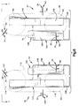
- Fig. 6 is a schematic elevational view, taken generally along the line 6-6 of Fig. 5A, illustrating the relationship between slats in the stacker assembly and jogger plates in the jogger assembly;
- Fig. 7 is a schematic plan view, taken generally along the line 7-7 of Fig. 6, further illustrating the relationship between the slats in the stacker assembly and the jogger plates in the jogger assembly; and
- Fig. 8 is a schematic pictorial illustration of a turntable drive assembly.
- An
apparatus 10 for use in stacking signatures is illustrated schematically in Fig. 1. Theapparatus 10 receives signatures 12 (Fig. 2) from aninfeed conveyor 14 in astream 16. Thesignatures 12 are conducted in thestream 16 with folded edge portions of the signatures leading and open edge portions of the signatures trailing. Thesignatures 12 are formed into anintermediate stack 18 in astacker assembly 20. - While the
intermediate stack 18 is supported in thestacker assembly 20, a jogger assembly 24 (Figs. 1 and 5A) is operable to jog the intermediate stack 18 (Fig. 2) of signatures to align opposite edge portions of the signatures in the intermediate stack of signatures. Thus, as theintermediate stack 18 of signatures is formed in thestacker assembly 20, the jogger assembly 24 (Fig. 1) is continuously operated to align the edge portions of the signatures. After theintermediate stack 18 of signatures has been formed in thestacker assembly 20, the intermediate stack of signatures is deposited onto a receiving platform, which, in the illustrated embodiment of the invention, is a turntable 26 (Figs. 2 and 3). When the receiving platform is theturntable 26, theintermediate stack 18 of signatures is received on amain stack 28 of signatures on theturntable 26. - Each time an
intermediate stack 18 of signatures is deposited on theturntable 26 by thestacker assembly 20, theturntable 26 rotates themain stack 28 through one-half of a revolution. By rotating themain stack 28 through one-half of a revolution each time anintermediate stack 18 of signatures is deposited on the main stack, the relatively thick folded edge portions of the signatures in the intermediate stacks are offset from each other. This results in themain stack 28 of signatures as being composed of layers of signatures having folded edge portions in one layer of signatures offset by 180° from the folded edge portions of the next succeeding layer of signatures. Therefore, the upper side of themain stack 28 of signatures is generally horizontal so that the main stack of signatures is relatively stable. - A suitable conveyor assembly (not shown) is provided to sequentially move
main stacks 28 of signatures from theturntable 26. Thus, after a sufficient number ofintermediate stacks 18 of signatures have been deposited on theturntable 26 by thestacker assembly 20 to form amain stack 28 of a desired size, the main stack is removed from theturntable 26 for further processing. Amain stack 28 of signatures can be completely removed from theturntable 26 in substantially less time then is required to form anintermediate stack 18 of signatures. It is contemplated that it may be desired to eliminate the accumulation ofintermediate stacks 18 on theturntable 26 and the formation of a relatively largemain stack 28. If this is the case, theturntable 26 may be replaced by a stationary platform. The conveyor assembly would be operated to move eachintermediate stack 18 off of the platform in turn before the next succeeding intermediate stack is received on the platform. - The infeed conveyor 14 (Fig. 2) feeds
signatures 12 to thestacker assembly 20 in astream 16 with folded edge portions of the signatures leading. Thesignatures 12 are supported in thestacker assembly 20 until sufficient signatures have accumulated to form anintermediate stack 18 of a desired size. A completedintermediate stack 18 of signatures is then transferred from thestacker assembly 20 to theturntable 26 and a next succeeding intermediate stack of signatures started without interrupting thestream 16 of signatures. - The
stacker assembly 20 includes a first plurality 32 (Fig. 1) of longitudinally extendingsignature support elements 34, hereinafter referred to as slats. Thestacker assembly 20 also includes asecond plurality 36 ofslats 34. Each of theslats 34 of thefirst plurality 32 of slats is moved along a circuitous path by afirst drive assembly 38. Each of theslats 34 of thesecond plurality 36 of slats is moved along a circuitous path by asecond drive assembly 40. - The
first drive assembly 38 moves each of theslats 34 in thefirst plurality 32 of slats along a first circuitous path, which has been indicated at 44 in Fig. 1. The firstcircuitous path 44 has a vertical left orouter run 46 along which theslats 34 of thefirst plurality 32 of slats move vertically upwardly. In addition, thecircuitous path 44 has a vertical right orinner run 48 along which theslats 34 of thefirst plurality 32 of slots move vertically downwardly. A lowersemi-circular connector portion 52 interconnects the lower ends of the outer andinner runs circuitous path 44. A semi-circularupper section 54 interconnects the upper ends of the outer andinner runs - The
first drive assembly 38 is operable to intermittently move theslats 34 in a clockwise direction (as viewed in Fig. 1) along thecircuitous path 44 between a loading position, indicated at 58 in Figs. 1 and 3, an intermediate position indicated at 60 in Figs. 1 and 3, and a standby position indicated at 62 in Figs. 1 and 3. Thefirst drive assembly 38 is operable to quickly index theslats 34 betweenloading position 58,intermediate position 60 andstandby position 62. The longitudinal central axes of theslats 34 are maintained horizontal and parallel to each other at all times during movement of the slats along the first circuitous path 44 (Fig. 1). - When a
slat 34 is in the loading position 58 (Figs. 1 and 3), a flatfront side surface 66 on theslat 34 is horizontal and faces upwardly. When theslat 34 has been moved along the firstcircuitous path 44 to theintermediate position 60, the flatfront side surface 66 of the slat is also horizontal. However, at this time, thefront side surface 66 of theslat 34 faces downwardly (see Figs. 1 and 3). When theslat 34 has been moved to thestandby position 62, the longitudinal central axis of the slat is still horizontal. However, at this time, the flatfront side surface 66 on theslat 34 is sloped at an angle of approximately 45° to a horizontal plane (Fig. 3). - Inner end portions 72 (Figs. 1 and 2) of the
slats 34 of thefirst plurality 32 of slats are connected to thefirst drive assembly 38. In the illustrated embodiment of the invention, thefirst drive assembly 38 includes a pair of flexible drive elements orchains 74 and 76 (Figs. 2 and 5A). Thechains circuitous path 44 and which is coextensive with a portion of thecircuitous path 44. It should be understood that althoughchains first drive assembly 38, it is contemplated that thechains - The
chains sprocket wheel assemblies 80 and 82 (Figs. 4 and 5A). The uppersprocket wheel assembly 80 includes a pair ofsprockets 86 and 88 (Fig. 4) which are interconnected by acylindrical hub 90. The lowersprocket wheel assembly 82 has the same construction as the uppersprocket wheel assembly 80. Thesprocket wheel assemblies - The
inner end portions 72 of theslats 34 are fixedly connected to thechains 74 and 76 (Figs. 2). Thechains slats 34 in a cantilevered relationship. Thus, theslats 34 extend horizontally outwardly from thechains chains circuitous path 44 to move theinner end portions 72 of theslats 34 along the circuitous path. - The
slats 34 in thesecond plurality 36 of slats are moved along a continuous circuitous path indicated schematically at 94 in Fig. 1. The continuouscircuitous path 94 has the same configuration and orientation as the continuouscircuitous path 44. Theslats 34 are moved along the continuouscircuitous path 94 in a counterclockwise direction between aloading position 98, anintermediate position 100 and a standby position 102 (Figs. 1 and 3). These positions correspond to and are horizontally aligned with theloading position 58,intermediate position 60 andstandby position 62 for thefirst plurality 32 ofslats 34. - During movement of the
slats 34 of thesecond plurality 36 of slats along the continuous circuitous path 94 (Fig. 1), the longitudinal axes of theslats 34 are maintained horizontal and parallel to the longitudinal axes of theslats 34 in thefirst plurality 32 of slats. When aslat 34 in thesecond plurality 36 of slats is at theloading position 98, a flat front side surface 66 (Figs. 1 and 3) of the slat is horizontal and faces upwardly. When aslat 34 has been moved from theloading position 98 to theintermediate position 100, thefront surface 66 is still horizontal. However, at this time, thefront surface 66 faces downwardly. When theslat 34 is moved to thestandby position 102, thesurface 66 slopes at an angle of approximately 45° to a horizontal plane. - A
slat 34 which is at theloading position 58 has a horizontalfront side surface 66 which is disposed in the same plane as the horizontal front side surface of a slat at the loading position 98 (Fig. 3). Theslats 34 at the loading positions 58 and 98 are spaced apart by a horizontal distance which is less than the length of a folded edge portion of asignature 12. Thesignatures 12 are fed into thestacker assembly 20 at a location which is above theslats 34 at the loading positions 58 and 98 (Figs. 2 and 3). Therefore, the signatures are supported on the upwardly facing coplanar front side surfaces 66 of theslats 34 at the loading positions 58 and 98 (Fig. 3). - When
sufficient signatures 12 have been accumulated on the slats at the loading positions 58 and 98, the first andsecond drive assemblies slats 34 along thecircuitous paths 44 and 94 (Fig. 1). As theslats 34 move downwardly from the loading positions 58 and 98, they are moved away from each other and rotated to deposit anintermediate stack 18 on themain stack 28 of signatures on theturntable 26. Thus, the vertical outer runs of thecircuitous paths 44 and 94 (Fig. 1) are spaced apart by a horizontal distance which is greater than the length of the folded edge portions of the signatures 12 (Figs. 1, 2 and 3). - The
second drive assembly 40 has the same construction as thefirst drive assembly 38 and is connected with theslats 34 of thesecond plurality 36 of slats in the same manner as in which thefirst drive assembly 38 is connected with the slats of thefirst plurality 32 of slats. Thus, thesecond drive assembly 40 includes a pair ofchains 110 and 112 (Fig. 5A) corresponding to thechains first drive assembly 38. Thechains circuitous path 94 and which is coextensive with a portion of thecircuitous path 94. - The
chains second drive assembly 40 extend around upper and lowersprocket wheel assemblies sprocket wheel assemblies sprocket wheel assemblies sprocket wheel assemblies first drive assembly 38 are rotatable. - The
end portions 72 of theslats 34 of thesecond plurality 36 of slats are connected with thechains first plurality 32 of slats. Theslats 34 of thesecond plurality 36 of slats are supported in a cantilevered relationship from thechains slats 34 in thesecond plurality 36 of slats are maintained in a parallel relationship with the horizontal longitudinal axes of the slats in thefirst plurality 32 of slats and with the horizontal axes about which thesprocket wheel assemblies circuitous paths 44 and 94 (Fig 1). - The
slats 34 in thefirst plurality 32 of slats anddrive chains circuitous path 46. Theslats 34 in thesecond plurality 36 of slats anddrive chains circuitous path 94. Movement of theslats 34 in thefirst plurality 32 of slats is coordinated with the movement of the slats in thesecond plurality 36 of slats. Theslats 34 in the first andsecond pluralities slat 34 in thefirst plurality 32 of slats and aslat 34 in thesecond plurality 36 of slats to cooperate with each other to lower signatures as the two slats move downwardly to their respective loading positions 58 and 98. In addition, once the two slats have reached their respective loading positions 58 and 98, the slats are stationary and cooperate with each other to support the signatures while anintermediate stack 18 ofsignatures 12 of a desired size is accumulated on the two slats. - The
drive assemblies second pluralities slats 34 are disposed on one side of a vertical plane 124 (Figs. 2 and 7). Thedrive chains 74 and 110 (Fig. 5A) are disposed in a plane which is parallel to the plane 124 (Fig. 2). Thedrive chains plane 124. Thecircuitous paths 44 and 94 (Fig. 1) are parallel to the plane 124 (Figs. 2 and 7). - The
slats 34 of the first andsecond pluralities vertical plane 124 throughout movement of the slats along thecircuitous paths 44 and 94 (Fig. 1). Therefore, afront side surface 66 on each of theslates 34 is perpendicular to the plane 124 (Figs. 2 and 7) throughout movement of the slats along thecircuitous paths slats 34 are disposed on a side of thevertical plane 124 opposite from thedrive assemblies 38 and 40 (Fig. 7) throughout movement of theslats 34 along thecircuitous paths sections 72 of theslats 34 extend through thevertical plane 124 and are connected with first andsecond drive assemblies - The
slats 34 support anintermediate stack 18 of signatures (Fig. 2) on a side of thevertical plane 124 opposite from the side on which thedrive assemblies intermediate stack 18 of signatures supported by theslats 34 is entirely disposed on the right (as viewed in Fig. 2) side of thevertical plane 124. The first andsecond drive assemblies 38 and 40 (Figs. 2 and 7) are entirely disposed on the left (as viewed in Fig. 2) side of thevertical plane 124. - The
vertical plane 124 extends parallel to thecircuitous paths slats 34 are moved. Thesprocket assemblies drive assemblies sprocket wheel assemblies vertical plane 124. The horizontal longitudinal axes of theslats 34 are maintained parallel to the planes containing the axes of rotation of thesprocket wheel assemblies intermediate stack 18 of signatures extends through the parallel vertical planes containing the axes of rotation of thesprocket wheel assemblies - A main drive system 128 (Figs. 1, 2 and 3) is connected with the
drive assemblies main drive system 128 includes a main drive motor 130 (Fig. 1) which is connected with thedrive assemblies single revolution clutch 132. The single revolution clutch 132 (Figs. 2 and 3) drives amain drive belt 134. Thedrive belt 134 is intermittently driven to operate thedrive assemblies - Operation of the
drive assemblies slats 34 in thefirst plurality 32 of slats and the slats in the second plurality ofslats 36 between the loading positions 58 and 98,intermediate positions standby positions 62 and 102 (Fig. 3). Theslats 34 are indexed by thedrive assemblies circuitous paths 44 and 94 (Fig. 1). Theslats 34 are then stopped while an intermediate stack 18 (Fig. 3) of signatures accumulates on a pair ofslats 34 disposed at the loading positions 58 and 98. - After the slats have been stationary for a sufficient length of time to enable an
intermediate stack 18 of a desired height to accumulate on the slats at the loading positions 58 and 98, thesingle revolution clutch 132 effects operation of thedrive assemblies slats 34. This results in the intermediate stack of signatures being deposited on theturntable 26 as a pair ofslats 34 move away from the loading positions 58 and 98 and a next succeeding pair of slats move quickly from the standby positions 62 and 102 to the loading positions. It should be noted that theslats 34 can be readily moved into the stream 16 (Fig. 2) ofsignatures 12 from theinfeed conveyor 14 with minimum disturbance. This is because theslats 34 are of a relatively small width as measured on the front side surfaces 66 and perpendicular to the longitudinal central axes of the slats. - Although many different types of
single revolution clutches 132 could be used, in one specific embodiment of the invention, thesingle revolution clutch 132 was obtained from Warner Electric and was a Super CB-6 wrap spring clutch. Warner Electric has a pace of business at Beloit, Illinois. It should also be understood that an intermittent drive mechanism other than a single revolution clutch could be used if desired. - The jogger assembly 24 (Figs. 5A, 5B, 6 and 7) cooperates with the
stacker assembly 20 to jog anintermediate stack 18 of signatures while the intermediate stack of signatures is supported byslats 34. Thejogger assembly 24 includes a pair ofside plates 142 and 144 (Figs. 5A and 5B). Theside plate 142 extends into the central portion of the circuitous path 44 (Fig. 1). Theside plate 144 extends into the central portion of thecircuitous path 94. Theslats 34 in thefirst plurality 32 of slats are moved around theside plate 142 along the continuouscircuitous path 44 by thefirst drive assembly 38. Similarly, theslats 34 in thesecond plurality 36 of slats are moved around theside plate 144 along the continuouscircuitous path 94 by thesecond drive assembly 40. The loading positions 58 and 98 (Fig. 3) and the vertical inner runs of thecircuitous paths 44 and 94 (Fig. 1) are disposed between theside plates - The
side plate 142 of thejogger assembly 24 includes a vertical side section 148 (Fig. 5B). Theside section 148 extends parallel to the longitudinal axes of theslats 34 of thefirst plurality 32 of slats and perpendicular to the vertical plane 124 (Fig. 7). Although theside section 148 of thejogger side plate 142 extends perpendicular to thevertical plane 124, thejogger side plate 142 does not extend through thevertical plane 124. - The
side section 148 of the jogger side plate 142 (Fig. 5B) has a flatvertical side surface 152 which extends perpendicular to the vertical plane 124 (Fig. 7) and parallel to the longitudinal axes of theslats 34 of thefirst plurality 32 of slats. Theside surface 152 of thejogger side plate 142 is engageable with one end of anintermediate stack 18 of signatures supported in thestacker assembly 20. Theside surface 152 is reciprocated toward and away from the end of theintermediate stack 18 of signatures to jog the end portions of the signatures into alignment with each other. - A vertical end section 156 (Fig. 5B) of the
jogger side plate 142 extends perpendicular to theside section 148 and parallel to the vertical plane 124 (Fig. 7). Theend section 156 of theside plate 142 has a flatvertical side surface 158 which extends parallel to thevertical plane 124 and is engageable with a side of theintermediate stack 18 of signatures. Theside surface 158 on theend section 156 engages the side of theintermediate stack 18 of signatures. Theside surface 158 is reciprocated toward and away from the side of theintermediate stack 18 of signatures to jog the folded edge portions of the signatures into alignment with each other. - The side plate 144 (Fig. 5B) of the
jogger assembly 24 has a construction which is similar to the construction of theside plate 142. Thus, theside plate 144 includes aside section 168 having a flat vertical side surface 172 (Fig. 7) which extends perpendicular to thevertical plane 124. Theside surface 172 on theside section 168 extends parallel to theside surface 152 on theside section 148 of thejogger side plate 142. Theside surface 172 on theside section 168 of thejogger side plate 144 is parallel to the longitudinal axes of theslats 34 in thesecond group 36 of slots throughout movement of the slats along the circuitous path 94 (Fig. 1). The vertical portions of thecircuitous paths slats 34 move downwardly are disposed between thejogger side plates - An
end section 176 on the jogger side plate 144 (Fig. 5B) extends perpendicular to theside section 168 and is parallel to thevertical plane 124. Theend section 176 has avertical side surface 178 disposed in the same plane as thevertical side surface 158 on theend section 156 of theside plate 142. Theend sections jogger side plates drive assemblies side surface 178 is reciprocated toward and away from the side of theintermediate stack 18 of signatures to jog the folded edge portions the signatures into alignment with each other. - The flat side surface 172 (Fig. 7) on the
side section 168 is engageable with an end of anintermediate stack 18 opposite from the end which is engaged by theside surface 152 on theside section 148 of theside plate 142. Theside surface 178 disposed on theend section 176 of theside plate 144 is engageable with the side surface of theintermediate stack 18 of signatures which is the same as the side surface of the intermediate stack which is engaged by theside surface 158 on theend section 156. The folded edge portions of thesignatures 12 are engaged by theend sections - In addition to the
side plates jogger assembly 24 has a pair ofback plates 184 and 186 (Figs. 5A and 7). Theback plates - The
back plate 184 has anend section 188 with a flat vertical side surface 190 (Fig. 7) which extends parallel to theflat side surface 158 on theend section 156 of theside plate 142 and parallel to thevertical plane 124. Theside surface 190 on theend section 188 of theback jogger plate 184 is engageable with a side of anintermediate stack 18 of signatures supported by thestacker assembly 20. Theside surface 190 on the jogger backplate 124 is reciprocated toward and away from the side of theintermediate stack 18 opposite from the folded edge portions of thesignatures 12 to jog the open edge portions of the signatures into alignment with each other. - The jogger back
plate 186 has anend section 194 with avertical side surface 196. Theside surface 196 on theend section 194 of thejogger plate 186 is disposed in the same vertical plane as theside surface 190 on theend section 188 of the jogger backplate 184. Theside surface 196 is engageable with the same side of anintermediate stack 18 of signatures as is theside surface 190. Theside surface 196 on the jogger backplate 186 is reciprocated toward and away from the side of theintermediate stack 18 opposite from the folded edge portions of thesignatures 12 to jog the open edge portions of the signatures into alignment. - The side surfaces 190 and 196 on the jogger back
plates intermediate stack 18 opposite from a side engaged by the side surfaces 158 and 178 on thejogger side plates side surface 196 on the jogger backplate 186 extends parallel to theside surface 178 on theend section 176 of thejogger side plate 144 and to thevertical plane 124. The side surfaces 190 and 196 on the jogger backplates slats 34 in theloader assembly 20 and parallel to thevertical plane 124. - A pair of
eccentric drive assemblies 202 and 204 (Figs. 5A and 5B) are provided to oscillate thejogger plates eccentric drive assemblies drive disks drive disks jogger plates - The
drive disks drive disks side sections 148 and 168 (Fig. 5B of thejogger side plates stacker assembly 20. In addition, oscillation of thedrive disks end sections jogger side plates intermediate stack 18 which extends between the opposite ends of the stack. - The
jogger side plates jogger side plates jogger side plates vertical plane 124. The jogger backplates side plates stacker assembly 20. - A stack length adjustment screw 220 (Fig. 5A) having opposite hand threads is rotatable to adjust the distance between the
jogger side plates stack width adjustment 222 is operable to actuate theeccentric drive assemblies disks disks end sections back plates end sections side plates end sections plates end sections jogger side plates - A drive assembly 226 (Fig. 5A) for the
eccentric drive assemblies disks jogger plates intermediate stack 18 of signatures while the signatures are supported by thestacker assembly 20. Thedrive assembly 226 and the eccentric drives 202 and 204 are located outwardly from the free ends of the cantileveredslats 34. Thus, theentire jogger assembly 24 is disposed on a side of the vertical plane 124 (Fig. 7) which is opposite from the first andsecond drive assemblies - The
turntable 26 is disposed beneath theslats 34 of thestacker assembly 20 and thejogger plates jogger assembly 24. Theturntable 26 receives intermediate stacks 18 (Fig. 2) from thestacker assembly 20. Theturntable 26 rotates amain stack 28 through one-half of a revolution to offset the folded edges of anintermediate stack 18 from the folded edges of the next succeeding intermediate stack. This results in the main stack being relatively level and stable. - The
turntable 26 has a rotatable circular platform 234 (Fig. 2). A plurality ofupstanding side walls 236 and 238 (Fig. 3) are disposed on theplatform 234. Theside walls main stack 28 of signatures to hold the stack in position on theplatform 234 during rotation of the platform. - A
drive assembly 242 is (Fig. 8) connected to a central portion of the platform 234 (Figs. 2 and 3). Thedrive assembly 242 is operable to rotate theplatform 234 about a vertical axis which extends through the center of anintermediate stack 18 supported in thestacker assembly 20. Thus, theplatform 234 is rotatable about a vertical central axis 244 (Figs. 2 and 3) which extends through the center of themain stack 28 and through the center of theintermediate stack 18 supported by thestacker assembly 20 above theturntable 26. - The vertical
central axis 244 of thecircular turntable platform 234 is disposed midway between thecircuitous paths slats 34 disposed at the loading positions 58 and 98 (Fig. 3). Thecentral axis 244 of theturntable 26 extends parallel to the side surfaces 152 and 172 (Fig. 7) on theside sections jogger side plates central axis 244 of the turntable is disposed midway between the side surfaces 152 and 172 on thejogger side plates central axis 244 of theturntable 26 extends parallel to and is disposed midway between the side surfaces on theend sections jogger side plates 142 and 144 (Fig. 7) and the side surfaces 190 and 196 on the jogger backplates - The
platform 234 has a flat circular upwardly facingside surface 248 which is disposed in a horizontal plane and extends parallel to the longitudinal axes of theslats 34 in the stacker assembly 20 (Fig. 2). The flatupper side surface 248 of theturntable 26 supports themain stack 28 of signatures for rotation about thecentral axis 244 of the turntable. - The
drive assembly 242 is operable to rotate theturntable 26 about thecentral axis 244 to offset the folded edge portions of succeedingintermediate stacks 18 of signatures deposited on themain stack 28 of signatures on theturntable 26. To offset the folded edge portions of theintermediate stacks 18 of signatures relative to themain stack 28, thedrive assembly 242 is operable to rotate theplatform 234 through 180° immediately after oneintermediate stack 18 of signatures is deposited on theturntable 26 and before the next succeeding intermediate stack is deposited on the turntable. - Although the drive assembly 242 (Fig. 8) could be constructed in such a manner as to sequentially rotate the turntable through 180° increments in the same direction, the drive assembly is constructed so as to sequentially rotate the turntable through 180° increments in opposite directions. Thus, the
drive assembly 242 rotates theplatform 234 in a clockwise direction (as viewed in Fig. 4) through 180° before oneintermediate stack 18 of signatures is deposited on the platform. Thedrive assembly 242 then rotates theplatform 234 through 180° in a counterclockwise direction (as viewed in Fig. 4) before the next succeedingintermediate stack 18 of signatures is deposited on the platform. - The
turntable drive assembly 242 includes a cylindrical drive post 254 (Fig. 8) having a central axis which is coincident with thecentral axis 244 of theturntable 26. Thedrive post 254 is fixedly secured to the bottom of theplatform 234. Ahelical cam groove 256 is formed in thedrive post 254 and extends for 180° about the circumference of the drive post. Thecam groove 256 has a central axis which is also coincident with thecentral axis 244 of thedrive assembly 242. - A
cylindrical cam follower 260 is mounted on acarriage 262 and extends into thehelical cam groove 256. A plurality ofguide rollers 264 on thecarriage 262 engage linearvertical edge portions drive post 254. A piston andcylinder type motor 278 is connected with thecarriage 262 and is operable to reciprocate thecarriage 262 along the guide bars 272 and 274. - The
carriage 262 is moved vertically upwardly along a linear path from the lowered position of Fig. 8 upon operation of themotor 278. As thecarriage 262 moves upwardly, thecam follower 260 cooperates with thehelical cam groove 256 to rotate thedrive post 254 through 180° about thecentral axis 244. After anintermediate stack 18 of signatures has been deposited on theturntable 26, the direction of operation of themotor 278 is reversed to move thecarriage 262 andcam follower 260 downwardly along thedrive post 254. As this occurs, the cooperation between thecam follower 260 and thehelical cam groove 256 results in the drive post being rotated through 180° in the opposite direction. - A plurality of rollers 282 (Fig. 8) cooperate with an
annular groove 284 formed in the upper end portion of thedrive post 254 to hold the drive post against axial movement. Similarly, a plurality ofrollers 286 cooperate with anannular groove 288 formed in the lower end portion of thedrive post 254 to hold the drive post against axial movement. - In the illustrated embodiment of the invention, the
drive post 254 is rotated by cooperation between acam follower 260 and ahelical groove 256 formed in the drive post. It is contemplated that a helical cam track could be provided on the outside of thedrive post 254 and engaged by a suitable cam follower. In the illustrated embodiment of the invention, thehelical cam groove 256 extends for 180° about the circumference of thedrive post 254. It is contemplated that thecam groove 256 could be constructed in such a manner as to extend through 360° about thecam post 254. If this was done, themotor 278 would be operated to move thecam follower 260 along half of the length of the cam groove in order to rotate the drive post through 180° each time anintermediate stack 18 of signatures is deposited on theturntable 26. - It may be desired to eliminate the compensation for the thick folded edge portions of the
signatures 12. In this situation, the turntable may be replaced by a stationary platform or theturntable drive assembly 242 may be temporarily rendered inactive. - During operation of the
apparatus 10, the infeed conveyor 14 (Fig. 2) conducts acontinuous stream 16 ofsignatures 12 to thestacker assembly 20 with folded edge portions of the signatures leading. As thesignatures 12 enter thestacker assembly 20, the folded edge portions of the signatures impact against theend sections 156 and 176 (Figs. 5B and 7) on thejogger side plates signatures 12 are engaged by the side surfaces 152 and 172 on thejogger side plates incoming signatures 12 with a partially formed intermediate stack 18 (Fig. 2) of signatures supported on a pair ofslats 34 at the loading positions 58 and 98 (Fig. 3). - The
signatures 12 then move downwardly toward the upper end of the partially formedintermediate stack 18. As thesignatures 12 move downwardly, the open trailing edge portions of the signatures engage theend sections 188 and 194 (Fig. 7) on the jogger backplates end sections back plates end sections jogger side plates - While an
intermediate stack 18 of signatures having a desired height is being accumulated on a pair ofslats 34 in the stacker assembly 20 (Fig. 3), theturntable drive assembly 242 rotates theturntable platform 234 through 180°. Thus, the motor 278 (Fig. 8) is operated to raise thecarriage 262 from the lower end of thedrive post 254 to the upper end of the drive post. This rotates theturntable platform 234 through 180° in a counterclockwise direction (as viewed in Fig. 1). - Rotation of the
turntable platform 234 results in the folded edge portions of the immediately precedingintermediate stack 18 of signatures being moved from a position disposed to the left (as viewed in Fig. 2) of thecentral axis 244 of theturntable 26 to a position to the right of the turntable axis. Thus, the folded edge portions of the uppermostintermediate stack 18 of signatures on themain stack 28 are moved from a position directly beneath the folded edge portions of theintermediate stack 18 being accumulated in thestacker assembly 20 to a position to the right (as viewed in Fig. 2) of theaxis 244 and immediately beneath the open edge portions of the signatures being accumulated in theintermediate stack 18 in thestacker assembly 20. - While the
signatures 12 are being accumulated in thestacker assembly 20 to form theintermediate stack 18, theside sections 148 and 168 (Figs. 5B and 7) of thejogger side plates immediate stack 18 of signatures by theeccentric drive assemblies end sections jogger side plates signatures 12 on one side of theintermediate stack 18. Similarly, theend sections plates signatures 12 on an opposite side of theintermediate stack 18. By continuously jogging thesignatures 12 in theintermediate stack 18, the edge portions of the signatures are accurately aligned with each other to form an intermediate stack with well defined and relatively smooth side and end surfaces. - Once an
intermediate stack 18 of a desired size has been accumulated on a pair ofslats 34 at the loading positions 58 and 98, thesingle revolution clutch 132 in themain drive system 128 is engaged. Themain drive system 128 then operates thedrive assembly 38 to index theslats 34 of thefirst plurality 32 of slats in a clockwise direction along the first circuitous path 44 (Fig. 1). At the same time, themain drive system 128 operates thedrive assembly 40 to index theslats 34 in thesecond plurality 36 of slats in a counterclockwise direction along the secondcircuitous path 94. - As the
slats 34 are moved downwardly from the loading positions 58 and 98, the front side surfaces 66 of the slats are tipped downwardly and moved sidewardly to release theintermediate stack 18 of signatures for downward movement toward theturntable 26. As theintermediate stack 18 of signatures begins to move downwardly relative to theslats 34, thejogger assembly 24 continuously jogs the ends and sides of the intermediate stack to maintain thesignatures 12 in alignment with each other. Thus, thejogger assembly 24 functions to promote alignment of thesignatures 12 from the time the signatures are fed into the upper portion of thestacker assembly 20, through the formation of anintermediate stack 18, and through at least a portion of the depositing of the intermediate stack on theturntable 26. - As the
slats 34 move downwardly and sidewardly away from the loading positions 58 and 98, the next succeedingslats 34 move downwardly from the standby positions 62 and 102. Thus, themain drive system 128 is operable to quickly move theslats 34 downwardly from theirstandby positions slats 34 are relatively long and narrow, the slats can easily move into thestream 16 of signatures with minimal interference. - As the downward movement of the
slats 34 along the inner runs of the first and secondcircuitous paths last signature 12 being fed onto theintermediate stack 18. The downwardly movingslats 34 propel this last signature downwardly toward theintermediate stack 18. At the same time, the horizontalupper sides 66 of theslats 34 move into position to receive the next succeeding signature in the stream of signatures. During continued downward movement of theslats 34 away from the standby positions 62 and 102 toward the loading positions 58 and 98, a few signatures are accumulated on theslats 34. - The
slats 34 are quickly moved to the loading positions 58 and 98 with their upwardly facing front side surfaces 66 disposed in a common horizontal plane. The operation of themain drive system 128 is then interrupted and theslats 34 remain stationary at the loading positions 58 and 98. As a pair of slats in the first andsecond pluralities circuitous paths circuitous paths intermediate positions - As soon as an
intermediate stack 18 of signatures has been deposited on themain stack 28 of signatures on theturntable 26, theturntable drive assembly 242 is again operated. Theturntable platform 234 is then rotated back through 180° in a clockwise direction (as viewed in Fig. 1). Thus, the turntable drive motor 278 (Fig. 8) moves thecam follower 260 back downwardly along thehelical cam groove 256 to rotate theplatform 234 in a clockwise direction (as viewed in Figs. 1 and 4). This results in the folded edge portions of succeedingintermediate stacks 18 of signatures accumulating in themain stack 28 of signatures with their folded edge portions offset by 180° relative to each other. - The present invention relates to a new and
improved apparatus 10 for use in stackingsignatures 12. Theapparatus 10 includes first andsecond pluralities slats 34. One of theslats 34 of thefirst plurality 32 of slats cooperates with one of the slats of thesecond plurality 36 of slats to support anintermediate stack 18 of signatures. Theslats 34 have longitudinal axes which are maintained parallel to each other and horizontal during movement of the slats along a pair of spaced apartcircuitous paths drive assemblies - A
jogger assembly 24 is operable to jog astack 18 of signatures supported by theslats 34 in thestacker assembly 20. Thejogger assembly 24 hasjogger plates circuitous paths slats 34 move. Thejogger plates slats 34 are disposed above a receiving platform, which may be theturntable 26. - The
turntable 26 includes aplatform 234 having a horizontalupper surface 248 which is parallel to longitudinal axes of theslats 34 and perpendicular toside surfaces jogger plates intermediate stack 18 ofsignatures 12 is transferred from thestacker assembly 20 to theturntable 26, theplatform 234 on which themain stack 28 of signatures is disposed is rotated through one-half of a revolution. Rotation of theplatform 234 offsets the relatively thick folded edge portions of signatures on theturntable 26 relative to the folded edge portions of the next succeedingintermediate stack 18 of signatures. Theplatform 234 is rotated by adrive assembly 242 which includes acam follower 260 which is moved vertically relative to ahelical cam 256 to rotate the platform.
Claims (14)
- An apparatus (10) for use in stacking signatures, said apparatus comprising first (32) and second (36) pluralities of longitudinally extending signature support elements (34), first drive means (38) for moving said first plurality (32) of signature support elements (34) along a first circuitous path (44), and second drive means (40) for moving said second plurality (36) of signature supports elements (34) along a second circuitous path (94) which is separate from the first circuitous path (44), each signature support element (34) of said first and second pluralities (32; 36) of signature support elements having surface means for engaging a lower side of a stack (18) of signatures to support the stack (18) of signatures, characterized in that said apparatus (10) further comprises jogger means (24) for jogging a stack (18) of signatures supported by one of said signature support elements (34) of said first plurality (32) of signature support elements (34) and one of said signature support elements (34) of said second plurality (36) of signature support elements (34), said jogger means (24) including a first jogger plate (142) engageable with a first end portion of a stack (18) of signatures, a second jogger plate (144) engageable with a second end portion of the stack (18) of signatures, and means for moving said first and second jogger plates relative to the stack (18) of signatures, whereby said first circuitous path (44) extends around said first jogger plate (142) and whereby said second circuitous path (94) extends around said second jogger plate (144).
- An apparatus according to claim 1, wherein said longitudinally extending signature support elements (34) have longitudinal axes extending transversely to a vertical plane, said first and second drive means (38, 40) being disposed on a first side of said vertical plane, each signature support element (34) of said first and second pluralities of signature support elements (34) extending through the vertical plane, and said surface means for engaging a lower side of said stack (18) of signatures support the stack (18) of signatures with the stack (18) of signatures entirely disposed on the second side of said vertical plane.
- An apparatus according to claim 2, wherein said jogger means (24) are disposed on the second side of said vertical plane for jogging the stack (18) of signatures.
- An apparatus according to one of the preceding claims, wherein said first jogger plate (142) has first side surface means (152) for engaging said first end portion of said stack (18) of signatures, said signature support elements (34) of said first plurality of signature support elements (34) having longitudinal axes which are maintained in a parallel relationship with said first side surface means (152) throughout movement of said first plurality of signature support elements (34) along the first circuitous path (44), said second jogger plate (144) having second surface means (172) for engaging said end portion of said stack (18) of signatures opposite from said first end portion, said signature support elements (34) of said second plurality of signature support elements (34) having longitudinal axes which are maintained in parallel relationship with said second side surface means (172) throughout movement of said second plurality of signature support elements (34) along the second circuitous path (94).
- An apparatus according to one of claims 1-3, wherein said first jogger plate (142) has first surface means (158) for engaging a first portion of said stack (18) of signatures, said signature support elements (34) of said first plurality of signature support elements (34) having longitudinal axes which are maintained in a perpendicular relationship with said first surface means (158) throughout movement of said first plurality of signature support elements (34) along the first circuitous path (44), said second jogger plate (144) having second surface means (178) for engaging a second portion of the stack (18) of signatures, said signature support elements (34) having longitudinal axes which are maintained in a perpendicular relationship with said second surface means (178) during movement of said second plurality of signature support elements (34) along the second circuitous path (94).
- An apparatus according to one of claims 1-3, wherein said first jogger plate (142) includes a first section (148) which extends parallel to the longitudinal axes of said first plurality of signature support elements (34) and a second section (156) which extends perpendicular to the longitudinal axes of said first plurality of signature support elements (34), said first section (148) of said first jogger plate (142) being engageable with a first end portion of a stack (18) of signatures, said second section (156) of said first jogger plate (142) being engageable with a first side portion of the stack (18) of signatures, said second jogger plate (144) including a first section (168) which extends parallel to the longitudinal axes of said second plurality of signature support elements (34) and a second section (176) which extends perpendicular to the longitudinal axes of said second plurality of signature support elements (34), said first section (168) of said second jogger plate (144) being engageable with a second end portion of the stack (18) of signatures opposite from the first end portion of the stack (18) of signatures, said second section (176) of said second jogger plate (144) being engageable with the first side portion of the stack (18) of signatures.
- An apparatus according to claim 1, wherein said first drive means (38) moves said first plurality of signature support elements (34) along the first circuitous path (44) with the longitudinal central axes of the signature support elements (34) of said first plurality of signature support elements (34) in a parallel relationship throughout movement of said first plurality of signature support elements (34) along the first circuitous path (44), said second drive means (40) moves said second plurality of signature support elements (34) along the second circuitous path (94) with the longitudinal central axes of the signature support elements (34) of said second plurality of signature support elements (34) in a parallel relationship throughout movement of said second plurality of signature support elements (34) along the second circuitous path (94).
- An apparatus according to claim 7, further including platform means (234) disposed beneath said first and second pluralities of signature support elements (34) for receiving stacks of signatures from said first and second pluralities of signature support elements (34), said platform means (234) having flat upper side surface means for supporting a stack (18) of signatures received from said first and second pluralities of signature support elements (34), said first and second pluralities of signature support elements (34) having longitudinal axes which are continuously maintained parallel to said flat upper side surface means of said platform means during movement of said first plurality of signature support elements (34) along said first circuitous path (44) and during movement of said second plurality of signature support elements (34) along said second circuitous path (94).
- An apparatus according to claim 1, wherein said first drive means (38) includes a first flexible drive element (74) which is movable along the first circuitous path (44) each signature support element (34) of said first plurality of signature support elements (34) being connected in a cantilevered relationship with said first flexible drive element (74), said second drive means (40) including a second flexible drive element (110) which is movable along the second circuitous path (94), each signature support element (34) of said second plurality of signature support elements (34) being connected in a cantilevered relationship with said second flexible drive element (110).
- An apparatus according to claim 1, wherein said first and second circuitous paths have vertical portions along which said signature support elements (34) are downwardly movable by said first and second drive means (38, 40), said vertical portions of said first and second circuitous paths being spaced apart by a distance which is less than the distance between opposite end portions of the stack (18) of signatures.
- An apparatus according to claim 1, wherein said first circuitous path (44) includes a vertical portion along which said signature support elements (34) of said first plurality of signature support elements (34) are moved by said first drive means (38), said second circuitous path (94) including a vertical portion along which said signature support elements (34) of said second plurality of signature support elements (34) are moved by said second drive means (40), said vertical portions of said first and second circuitous paths being at least partially disposed between said first and second jogger plates (142, 144).
- An apparatus according to claim 1, wherein said first circuitous path (44) includes a first portion along which said signature support elements (34) of said first plurality of signature support elements (34) are moved upwardly and a second portion along which said signature support elements (34) of said first plurality of signature support elements (34) are moved downwardly, said first portion of said first circuitous path (44) being disposed on a first side of said first jogger plate (142) and said second portion of said first circuitous path (44) being disposed on a second side of said first jogger plate (142), said second circuitous path (94) including a first portion along which said signature support elements (34) of said second plurality of signature support elements (34) are moved upwardly and a second portion along which said signature support elements (34) of said second plurality of signature support elements (34) are moved downwardly, said first portion of said second circuitous path (94) being disposed on a first side of said second jogger plate (144) and said second portion of said second circuitous path (94) being disposed on a second side of said second jogger plate (144).
- An apparatus according to claim 1, wherein said first jogger plate (142) includes a first section which extends parallel to the longitudinal axes of said first plurality of signature support elements (34) and a second section which extends perpendicular to the longitudinal axes of said first plurality of signature support elements (34), said first section of said first jogger plate (142) being engageable with the first end portion of the stack (18) of signatures, said second section of said first jogger plate (142) being engageable with a side portion of the stack (18) of signatures, said second jogger plate (144) including a first section which extends parallel to the longitudinal axes of said second plurality of signature support elements (34) and a second section which extends perpendicular to the longitudinal axes of said second plurality of signature support elements (34), said first section of said second jogger plate (144) being engageable with the second end portion of the stack (18) of signatures, said second section of said second jogger plate (144) being engageable with the side portion of the stack (18) of signatures.
- An apparatus according to claim 1, wherein each of said signature support elements (34) of said first plurality of signature support elements (34) has a first end portion connected with said first drive means (38) and a free end portion which is opposite from said first end portion, said jogger means (24) including a third jogger plate (184) which is disposed outwardly from the free end portions of said signature support elements (34) of said first plurality of signature support elements (34) and is engageable with a side portion of the stack (18) of signatures, each of said signature support elements (34) of said second plurality of signature support elements (34) having a first end portion connected with said second drive means (40) and a free end portion which is opposite from said first end portion, said jogger means (24) including a fourth jogger plate (186) which is disposed outwardly from the free end portions of said signature support elements (34) of said second plurality of signature support elements (34) and is engageable with the side portion of the stack (18) of signatures.
Applications Claiming Priority (2)
| Application Number | Priority Date | Filing Date | Title |
|---|---|---|---|
| US34360 | 1979-04-27 | ||
| US08/034,360 US5312223A (en) | 1993-03-19 | 1993-03-19 | Apparatus for stacking signatures |
Publications (3)
| Publication Number | Publication Date |
|---|---|
| EP0622319A2 EP0622319A2 (en) | 1994-11-02 |
| EP0622319A3 EP0622319A3 (en) | 1995-02-08 |
| EP0622319B1 true EP0622319B1 (en) | 1997-01-02 |
Family
ID=21875936
Family Applications (1)
| Application Number | Title | Priority Date | Filing Date |
|---|---|---|---|
| EP94103659A Expired - Lifetime EP0622319B1 (en) | 1993-03-19 | 1994-03-10 | Apparatus for stacking signatures |
Country Status (3)
| Country | Link |
|---|---|
| US (2) | US5312223A (en) |
| EP (1) | EP0622319B1 (en) |
| DE (1) | DE69401299T2 (en) |
Families Citing this family (17)
| Publication number | Priority date | Publication date | Assignee | Title |
|---|---|---|---|---|
| DE4328604C2 (en) * | 1993-08-25 | 1995-12-07 | Gaemmerler Hagen | Rotatable stacking chamber in a stacker for printed products |
| JP3618840B2 (en) * | 1995-07-25 | 2005-02-09 | キヤノン株式会社 | Bookbinding bundle conveying apparatus and bookbinding apparatus provided with the same |
| DE19615009B4 (en) * | 1996-04-16 | 2005-09-29 | Smb Schwede Maschinenbau Gmbh | Stacker with strapping device |
| EP0829441B1 (en) * | 1996-09-11 | 2002-04-24 | Grapha-Holding Ag | Device for ejecting stacked and printed sheets |
| US5865300A (en) * | 1996-10-04 | 1999-02-02 | Newsome; John R. | Presser assembly for turning conveyors |
| IT1292609B1 (en) * | 1997-06-09 | 1999-02-08 | Gd Spa | DEVICE AND METHOD FOR THE FORMATION OF ORDERED STACKS OF SHEETS OR GROUPS OF SHEETS, IN PARTICULAR BANKNOTES |
| DE19752262A1 (en) * | 1997-11-26 | 1999-05-27 | Segbert Gmbh & Co Kg | Device for aligning, pressing and ejecting packets of loosely stacked printed products |
| US6007293A (en) * | 1998-03-20 | 1999-12-28 | Webcrafters, Inc. | Signature bundle inverter |
| US6439830B2 (en) * | 1999-12-08 | 2002-08-27 | Total Mailroom Support, Inc. | Opening guard mechanism for printed product stacking device |
| US6761676B2 (en) * | 2001-09-06 | 2004-07-13 | Heidelberger Druckmaschinen Ag | Device for controlling printed products |
| DE10317948A1 (en) * | 2003-04-17 | 2004-10-28 | Gämmerler AG | handling system |
| US7278634B2 (en) * | 2003-07-31 | 2007-10-09 | Goss International Americas, Inc. | Device for controlling printed products |
| WO2007021763A2 (en) * | 2005-08-11 | 2007-02-22 | Packaging Progressions, Inc. | Interleaver stacker and loading system |
| EP2192067B1 (en) * | 2008-11-28 | 2013-09-18 | Müller Martini Holding AG | Stacking device for printed products |
| US8978870B2 (en) * | 2010-09-22 | 2015-03-17 | Bobst Mex Sa | Device for conveying bundles for a strapping machine |
| CH705846A1 (en) | 2011-12-07 | 2013-06-14 | Ferag Ag | Apparatus and method for assembling of flat products, in particular printing products. |
| CN110342313B (en) * | 2018-04-03 | 2021-10-26 | 深圳市红标点科技有限公司 | Piling machine |
Family Cites Families (26)
| Publication number | Priority date | Publication date | Assignee | Title |
|---|---|---|---|---|
| DE214321C (en) * | ||||
| US2793857A (en) * | 1954-06-11 | 1957-05-28 | Rauschenberger Willia Franklin | Section stacker |
| US2964160A (en) * | 1957-12-19 | 1960-12-13 | Bulletin Company | Machine for advancing articles |
| US3269089A (en) * | 1962-12-17 | 1966-08-30 | Us Envelope Co | Machine for banding envelopes |
| US3305104A (en) * | 1964-06-04 | 1967-02-21 | Stapling Machines Co | Cleat stacker |
| US3390508A (en) * | 1964-08-25 | 1968-07-02 | Winkler Fallert & Co Maschf | Apparatus for the interlaced packaging of folded printed matter |
| US3260191A (en) * | 1964-10-08 | 1966-07-12 | Miner Machine Company | Bundle tie feeder |
| US3280725A (en) * | 1965-03-19 | 1966-10-25 | Stanley Works | Strapping machine and system |
| FR1498021A (en) * | 1966-10-28 | 1967-10-13 | Bunn Co B | Apparatus for automatically tying, more particularly, substantially flat articles |
| US3532230A (en) * | 1968-04-12 | 1970-10-06 | Cutler Hammer Inc | High speed counter stacker for flexible articles |
| US3599807A (en) * | 1970-02-02 | 1971-08-17 | Cutler Hammer Inc | Article counter-stacker having mechanically operated gates on the stack-receiving table |
| US4183704A (en) * | 1976-10-29 | 1980-01-15 | Rima Enterprises | Compensating stacker for printed signatures |
| US4068567A (en) * | 1977-01-31 | 1978-01-17 | Cutler-Hammer, Inc. | Combined ejector-gate means for rotatable table of an article counter-stacker |
| US4285621A (en) * | 1979-11-14 | 1981-08-25 | Paper Converting Machine Company | Apparatus for stacking product |
| US4457656A (en) * | 1981-01-30 | 1984-07-03 | Nolan Systems, Inc. | Stack assembling apparatus and technique |
| US4554867A (en) * | 1984-03-19 | 1985-11-26 | Stobb, Inc. | Method and apparatus for handling a stack of sheets |
| JPS6127869A (en) * | 1984-07-13 | 1986-02-07 | Nichiro Kogyo Kk | Device for stacking small bundles of folding printed materials |
| CH663775A5 (en) * | 1984-10-01 | 1988-01-15 | Grapha Holding Ag | STACKING DEVICE. |
| US4678387A (en) * | 1985-03-01 | 1987-07-07 | Quipp Incorporated | Signature stacker |
| US4611533A (en) * | 1985-06-27 | 1986-09-16 | Harris Graphics Corporation | Tying apparatus |
| EP0234444B1 (en) * | 1986-02-17 | 1990-12-27 | Gunze Limited | Apparatus for handling signatures before binding |
| US4720229A (en) * | 1986-11-05 | 1988-01-19 | Rima Enterprises, Incorporated | Stack pusher |
| IT1210731B (en) * | 1987-05-13 | 1989-09-20 | Rom Srl | MACHINE FOR THE TRAINING OF STICKS OF SIGNATURES AND SIMILAR ITEMS |
| DE8709053U1 (en) * | 1987-07-01 | 1987-09-10 | Fripack AG, Baar | Device for grouping packages |
| DE3736868A1 (en) * | 1987-10-30 | 1989-05-11 | Benz & Hilgers Gmbh | Stacking apparatus on packaging machines for bags or the like |
| US5287162A (en) * | 1992-06-16 | 1994-02-15 | Xerox Corporation | Method and apparatus for correction of color registration errors |
-
1993
- 1993-03-19 US US08/034,360 patent/US5312223A/en not_active Expired - Lifetime
- 1993-05-24 US US08/066,901 patent/US5392700A/en not_active Expired - Lifetime
-
1994
- 1994-03-10 DE DE69401299T patent/DE69401299T2/en not_active Expired - Lifetime
- 1994-03-10 EP EP94103659A patent/EP0622319B1/en not_active Expired - Lifetime
Also Published As
| Publication number | Publication date |
|---|---|
| US5312223A (en) | 1994-05-17 |
| DE69401299T2 (en) | 1997-10-09 |
| EP0622319A2 (en) | 1994-11-02 |
| EP0622319A3 (en) | 1995-02-08 |
| US5392700A (en) | 1995-02-28 |
| DE69401299D1 (en) | 1997-02-13 |
Similar Documents
| Publication | Publication Date | Title |
|---|---|---|
| US5312223A (en) | Apparatus for stacking signatures | |
| EP0736469B1 (en) | Palletizing system | |
| CN1057195C (en) | Apparatus for processing a countinuous paste band | |
| US3331516A (en) | Apparatus for stacking copies of folded newspapers, periodicals or other similar articles | |
| US5060929A (en) | Sheet delivery device with auxiliary deposit table | |
| EP0309005B1 (en) | System for providing a laminate consisting of dough and fat | |
| EP0745547B1 (en) | Document set compiler and eject system | |
| US4502592A (en) | Apparatus for intermittently transporting stacks of paper sheets or the like | |
| DE69911092T2 (en) | Device for feeding, depositing and aligning sheets in a container for sheet stacks | |
| EP0249874A1 (en) | Method and apparatus for transporting signatures along a path between two conveyors | |
| US7828507B2 (en) | Stack turning apparatus with multiple drive means to straighten and eject stack from turntable | |
| US5098075A (en) | Apparatus for assembling and depositing signatures | |
| US4397229A (en) | Stacker-tyer | |
| EP0626330B1 (en) | Apparatus for use in handling signatures | |
| US5433582A (en) | Device for discharging papers | |
| US7798312B2 (en) | Compression passing roller | |
| DD203866A5 (en) | DEVICE FOR PRODUCING A CONTINUOUS WELLPAPPE RAILWAY | |
| US20090298661A1 (en) | Continuous folding process | |
| CA1052830A (en) | Moving pile separator and its use with a jogger | |
| US4964627A (en) | Apparatus and method for forming signatures into a V-configuration | |
| EP0165808B1 (en) | Continuous motion spiral stacker and process for use thereof | |
| CA1147202A (en) | Web fed printing collator processing unit and method | |
| EP0093987A2 (en) | Device for concentrating blanks which arrive side by side in a pile or a stack | |
| EP0068462A1 (en) | Stacker-tyer | |
| US7090212B2 (en) | Apparatus for producing a bound print item |
Legal Events
| Date | Code | Title | Description |
|---|---|---|---|
| PUAI | Public reference made under article 153(3) epc to a published international application that has entered the european phase |
Free format text: ORIGINAL CODE: 0009012 |
|
| 17P | Request for examination filed |
Effective date: 19940409 |
|
| AK | Designated contracting states |
Kind code of ref document: A2 Designated state(s): CH DE FR GB IT LI |
|
| PUAL | Search report despatched |
Free format text: ORIGINAL CODE: 0009013 |
|
| AK | Designated contracting states |
Kind code of ref document: A3 Designated state(s): CH DE FR GB IT LI |
|
| 17Q | First examination report despatched |
Effective date: 19950324 |
|
| GRAG | Despatch of communication of intention to grant |
Free format text: ORIGINAL CODE: EPIDOS AGRA |
|
| GRAH | Despatch of communication of intention to grant a patent |
Free format text: ORIGINAL CODE: EPIDOS IGRA |
|
| GRAH | Despatch of communication of intention to grant a patent |
Free format text: ORIGINAL CODE: EPIDOS IGRA |
|
| GRAA | (expected) grant |
Free format text: ORIGINAL CODE: 0009210 |
|
| AK | Designated contracting states |
Kind code of ref document: B1 Designated state(s): CH DE FR GB IT LI |
|
| PG25 | Lapsed in a contracting state [announced via postgrant information from national office to epo] |
Ref country code: IT Free format text: LAPSE BECAUSE OF FAILURE TO SUBMIT A TRANSLATION OF THE DESCRIPTION OR TO PAY THE FEE WITHIN THE PRESCRIBED TIME-LIMIT;WARNING: LAPSES OF ITALIAN PATENTS WITH EFFECTIVE DATE BEFORE 2007 MAY HAVE OCCURRED AT ANY TIME BEFORE 2007. THE CORRECT EFFECTIVE DATE MAY BE DIFFERENT FROM THE ONE RECORDED. Effective date: 19970102 |
|
| REG | Reference to a national code |
Ref country code: CH Ref legal event code: EP |
|
| RAP2 | Party data changed (patent owner data changed or rights of a patent transferred) |
Owner name: HEIDELBERG FINISHING SYSTEMS, INC. |
|
| REF | Corresponds to: |
Ref document number: 69401299 Country of ref document: DE Date of ref document: 19970213 |
|
| ET | Fr: translation filed | ||
| ET | Fr: translation filed |
Free format text: CORRECTIONS |
|
| REG | Reference to a national code |
Ref country code: CH Ref legal event code: NV Representative=s name: ROTTMANN, ZIMMERMANN + PARTNER AG |
|
| PLBE | No opposition filed within time limit |
Free format text: ORIGINAL CODE: 0009261 |
|
| STAA | Information on the status of an ep patent application or granted ep patent |
Free format text: STATUS: NO OPPOSITION FILED WITHIN TIME LIMIT |
|
| 26N | No opposition filed | ||
| REG | Reference to a national code |
Ref country code: GB Ref legal event code: IF02 |
|
| PGFP | Annual fee paid to national office [announced via postgrant information from national office to epo] |
Ref country code: GB Payment date: 20030224 Year of fee payment: 10 |
|
| PGFP | Annual fee paid to national office [announced via postgrant information from national office to epo] |
Ref country code: FR Payment date: 20030320 Year of fee payment: 10 |
|
| PGFP | Annual fee paid to national office [announced via postgrant information from national office to epo] |
Ref country code: CH Payment date: 20030403 Year of fee payment: 10 |
|
| PG25 | Lapsed in a contracting state [announced via postgrant information from national office to epo] |
Ref country code: GB Free format text: LAPSE BECAUSE OF NON-PAYMENT OF DUE FEES Effective date: 20040310 |
|
| PG25 | Lapsed in a contracting state [announced via postgrant information from national office to epo] |
Ref country code: LI Free format text: LAPSE BECAUSE OF NON-PAYMENT OF DUE FEES Effective date: 20040331 Ref country code: CH Free format text: LAPSE BECAUSE OF NON-PAYMENT OF DUE FEES Effective date: 20040331 |
|
| GBPC | Gb: european patent ceased through non-payment of renewal fee |
Effective date: 20040310 |
|
| REG | Reference to a national code |
Ref country code: CH Ref legal event code: PL |
|
| PG25 | Lapsed in a contracting state [announced via postgrant information from national office to epo] |
Ref country code: FR Free format text: LAPSE BECAUSE OF NON-PAYMENT OF DUE FEES Effective date: 20041130 |
|
| REG | Reference to a national code |
Ref country code: FR Ref legal event code: ST |
|
| PGFP | Annual fee paid to national office [announced via postgrant information from national office to epo] |
Ref country code: DE Payment date: 20100329 Year of fee payment: 17 |
|
| PG25 | Lapsed in a contracting state [announced via postgrant information from national office to epo] |
Ref country code: DE Free format text: LAPSE BECAUSE OF NON-PAYMENT OF DUE FEES Effective date: 20111001 |
|
| REG | Reference to a national code |
Ref country code: DE Ref legal event code: R119 Ref document number: 69401299 Country of ref document: DE Effective date: 20111001 |