EP0622016B1 - Verbesserung an einer Vorrichtung zum kontrollierten Bewässern von Pflanzen - Google Patents
Verbesserung an einer Vorrichtung zum kontrollierten Bewässern von Pflanzen Download PDFInfo
- Publication number
- EP0622016B1 EP0622016B1 EP94830195A EP94830195A EP0622016B1 EP 0622016 B1 EP0622016 B1 EP 0622016B1 EP 94830195 A EP94830195 A EP 94830195A EP 94830195 A EP94830195 A EP 94830195A EP 0622016 B1 EP0622016 B1 EP 0622016B1
- Authority
- EP
- European Patent Office
- Prior art keywords
- bath
- water
- container
- plants
- chamber
- Prior art date
- Legal status (The legal status is an assumption and is not a legal conclusion. Google has not performed a legal analysis and makes no representation as to the accuracy of the status listed.)
- Expired - Lifetime
Links
Images


Classifications
-
- A—HUMAN NECESSITIES
- A01—AGRICULTURE; FORESTRY; ANIMAL HUSBANDRY; HUNTING; TRAPPING; FISHING
- A01G—HORTICULTURE; CULTIVATION OF VEGETABLES, FLOWERS, RICE, FRUIT, VINES, HOPS OR SEAWEED; FORESTRY; WATERING
- A01G27/00—Self-acting watering devices, e.g. for flower-pots
- A01G27/001—Self-acting watering devices, e.g. for flower-pots with intermittent watering means
Definitions
- the invention as claimed therefore provides a reliable irrigation device that has no need of electric or water supplies, and which supplies water to the plants notwithstanding any impurities in the water.
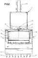
- the bath 3 is pivoted, as will be described in more detail hereinbelow, on the container 1 on its horizontal centre of gravity, denoted by X and calculated to correspond to a point whereat the water level is just below the rim of the bath 3.
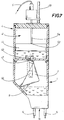
- the chamber 41 is provided with a stiffened pipe end 5a corresponding to a free end of the water supply pipe 5, (the pipe end 5a can even be constituted by a second pipe, stiffer than the original water supply pipe 5).
- the pipe end 5a has its free end turned downwards, constituting a vertical stop to the thrust developing from the volume of water contained in the chamber on the floating piston 44.
- the bath 3 as in the applicant's previous patent IT 1,234,704, receives the water while remaining stable and in its original position until the water reaches up to just below its rim. At this point the centre of gravity axis X is just operative, but once the above-mentioned level is surpassed, the natural centre of gravity of the bath 3 moves, causing the bath 3 to rotate on its axis X and its side 3a to move into a position where it is practically facing the holes 2 (see figure 4, broken lines), whereat the water is poured into the container 1. Then the empty bath 3 returns into its original position, helped by a plate 8 acting as counterweight. The water channels into the holes 2 and thus into the pipes 14, whereby it is conducted to the vases 13 containing the plants to be watered.
- the volume of the bath 3 can be changed, or a second bath 3 might be provided, having a greater volume than the first and being directly pivoted on the container 1 downstream of the bath 3, so as to empty at longer time intervals.
- the rod 47 is supported by a support 61 pivoted on an axis Z solid to the container 1 or the chamber 41.
- the support 61 exhibits a striker portion 62, camshaped in the figures, for the bath 3, which interacts with the bath 3 when the latter is rotated.
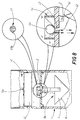
- Figure 8 shows how the outlet opening 43 can be provided with a circular opening exhibiting a slot 43a.
- a seating 64 might be provided in the chamber 41 at the outlet opening 43 to receive (by effect of force of gravity) a sphere of heavier material than water and having a diameter which is superior to that of the circular portion of the outlet opening 43. In this way, water contained in the chamber 41 can flow out through the slot 43a, falling into the underlying bath 3.
- the sphere 63 is displaced allows a greater flow of water to pass, in order to add the action of the rod 47 to the drawing action of the greater-than normal flow of water through the slot 43a.
- the flow of water is indicated by un-numbered arrows or drops.
Landscapes
- Engineering & Computer Science (AREA)
- Water Supply & Treatment (AREA)
- Life Sciences & Earth Sciences (AREA)
- Environmental Sciences (AREA)
- Devices For Medical Bathing And Washing (AREA)
- Feeding, Discharge, Calcimining, Fusing, And Gas-Generation Devices (AREA)
- Control Of Non-Electrical Variables (AREA)
- Float Valves (AREA)
- Devices For Dispensing Beverages (AREA)
Claims (9)
- Eine Vorrichtung zum kontrollierten Bewässern von Pflanzen, insbesondere für Balkon- oder Zimmerpflanzen, enthaltend:
einen Wasserbehälter (1), versehen mit einer Reihe von Auslassöffnungen (2), die in den Boden (1a) des Behälters (1) eingearbeitet sind;
eine Wanne (3) zur Aufnahme von Wasser aus einer Wasserquelle (12), die in dem Behälter (1) angeordnet ist und eine nach oben gerichtete offene Seite (3a) aufweist, und die mit ihrer eigenen horizontalen Achse (X) an den Behälter (1) angelenkt ist, welche Achse dabei durch das Baryzentrum der Wanne (3) verläuft, wenn diese bis zu dem oberen Rand der genannten Wanne (3) selbst mit Wasser gefüllt ist;
Mittel (4) zur Regulierung der Wasserzulaufmenge in die Wanne (3), welche auf eine erste Wasserzulaufleitung (5) zu der Wanne (3) wirken; wobei die genannten Mittel (4) oberhalb der offenen Seite (3a) der Wanne (3) angeordnet sind und den Zufluss des Wassers in die Wanne (3) regulieren, und zwar durch eine Auslassöffnung (43);
Mittel (8) zum Festhalten der Wanne (3) in einer Position, in welcher die offene Seite (3a) in eine nach oben gehende Richtung zeigt, so dass diese Wasser aus der ersten Wasserzulaufleitung (5) bis zu dem Punkt aufnimmt, in dem das Wasser an einen Stand oberhalb der genannten horizontalen Achse gelangt; wobei die genannten Mittel (8) eine weitere Aufgabe haben, und zwar die Rückführung der Wanne (3) in die genannte Position, in welcher die offene Seite (3a) in die nach oben gehende Richtung zeigt, nachdem die Wanne (3) dadurch, dass das eingelaufene Wasser auf einen Stand über der genannten horizontalen Achse (X) gelangt ist, aus dein Gleichgewicht geraten ist und das genannte Wasser in den Behälter (1) entladen hat, gedreht war; dadurch gekennzeichnet, dass eine Stange (47), die an die Wanne (3) angeschlossen ist und einen Kleineren Querschnitt als die genannte Auslassöffnung (43) hat, in wenigstens einer Position der Wanne (3) gleitbar in die genannte Auslassöffnung (43) eingesetzt ist, so dass ein Ansammeln von aus Wasserunreinheiten kommenden Rückständen an der genannten Auslassöffnung (43) verhindert wird; und weiter gekennzeichnet, dass die Mittel (4) zur Regulierung der Wasserzufuhr wie folgt enthalten:
eine Kammer (41), verbunden mit dem Behälter (1) und versehen mit:
einer Einlassöffnung (42), die an die erste Wasserzulaufleitung (5) angeschlossen ist;
der genannten Auslassöffnung (43), um es dem Wasser zu erlauben, in die Wanne (3) zu fliessen;
einen Schwimmerkolben (44) mit einer Kleineren Oberfläche als der geringste interne horizontale Querschnitt der Kammer (41), welcher vertikal im Inneren der Kammer (41) gleitbar ist, und der daran gehindert werden kann, über bestimmte Höhen zwischen der Einlassöffnung (42) und der Auslassöffnung (43) hinaus zu reichen, so dass ein Wasseranschlag in der Kammer (41) vorbestimmt und reguliert werden kann;
ein versteiftes freies Ende (5a) der ersten Wasserzulaufleitung (5), welches dem Schwimmerkolben (44) zugewandt ist und die Aufgabe eines Anschlags hat, um das vertikale Aufwärtsgleiten des genannten Schwimmerkolbens (44) zu stoppen, das sich aus einem Druck nach oben ergibt, der von dem Wasseranschlagvolumen in der Kammer (41) ausgeübt wird. - Eine Vorrichtung zum kontrollierten Bewässern von Pflanzen nach Patentanspruch 1, dadurch gekennzeichnet, dass die Stange (47) mit einer Halterung (61) verbunden ist, angelenkt an eine fest mit dem Behälter (1) oder der Kammer (41) verbundenen horizontalen Achse (Z), und einen als Anschlag ausgebildeten Abschnitt (62) aufweist, der mit der Wanne (3) zusammenwirkt, wenn die Wanne (3) zum Ablassen des Wassers gedreht ist; wobei die genannte Halterung (61) zwischen einer ersten Position, in welcher sie der Kraft ihres eigenen Gewichtes unterliegt und die Stange (47) sich ausserhalb der Auslassöffnung (43) befindet, und einer zweiten Position, in welcher sie einem Druck durch die Wanne (3) unterliegt, wenn sich die Wanne (3) in ihrer gedrehten Position befindet und die Stange (47) in die Auslassöffnung (43) eingeschoben ist, bewegt werden kann, so dass die Stange (47) in einer wechselweise Bewegung jeweils zum Füllen und zum Leeren der Wanne (3) versetzt wird.
- Eine Vorrichtung zum kontrollierten Bewässern von Pflanzen nach Patentanspruch 1, dadurch gekennzeichnet, dass die Wanne (3) an der Auslassöffnung (43) mit dem Behälter (1) durch eine Gabel (45) verbunden ist, welche zwei Stützpunkte (46) aufweist, die an der horizontalen Achse (X) auf die Wanne (3) einwirken, sowie einen Befestigungspunkt, der durch die genannte Stange (47) beschrieben wird, gleitbar im Inneren der Auslassöffnung (43) und verbunden mit einem Federelement (48), welches eine entgegenwirkende elastische Reaktion (R) zu der Gewichtskraft (P) erzeugt, die bei gefüllter Wanne (3) nach unten ausgeübt wird, wobei die genannte Stange (47) einer wechselweisen Bewegung beim Füllen und beim Leeren der Wanne (3) unterzogen wird.
- Eine Vorrichtung zum kontrollierten Bewässern von Pflanzen nach Patentanspruch 2 oder 3, dadurch gekennzeichnet, dass das freie Ende (5a) der Wasserzulaufleitung (5) mit Mitteln zur vertikalen Positionierung versehen ist, so dass das genannte freie Ende (5a) innerhalb der Kammer (41) auf verschiedene Höhen eingestellt werden kann, und zwar nach einer Meßskala (49) für die Höhenmarkierungen.
- Eine Vorrichtung zum kontrollierten Bewässern von Pflanzen nach Patentanspruch 2 oder 3, dadurch gekennzeichnet, dass das freie Ende (5a) mit Mitteln zur vertikalen Positionierung des genannten freies Endes (5a) auf verschiedenen Höhen innerhalb der Kammer (41) versehen ist, und zwar nach einer Meßskala (49) für die Höhenmarkierungen, welche Mittel einen Sitz (50) mit einer durchgehenden Öffnung enthalten, welche gleich einem äusseren Querschnitt des freien Endes (5a) ist und einen dicht abschliessenden Durchlass für das freie Ende (5a) selbst bildet.
- Eine Vorrichtung zum kontrollierten Bewässern von Pflanzen nach Patentanspruch 3, dadurch gekennzeichnet, dass das Federelement (48) ein flexibles Metallplättchen (48a) enthält, das mit seinem einen Ende an einen festen Punkt an der Kammer (41) oder an dem Behälter (1) angeschlossen ist und mit dem anderen Ende an die Stange (47).
- Eine Vorrichtung zum kontrollierten Bewässern von Pflanzen nach Patentanspruch 3, dadurch gekennzeichnet, dass das Federelement (48) eine Feder (48b) enthält, die zwischen einem Teil der Gabel (45) und einem festen Punkt an der Kammer (41) oder an dem Behälter (1) wirkt.
- Eine Vorrichtung zum kontrollierten Bewässern von Pflanzen nach Patentanspruch 1, dadurch gekennzeichnet, dass der Behälter (1) entsprechend zu den Auslassöffnungen (2) mit einer Anzahl von Zellen (11) versehen ist, welche Zellen (11) nach oben hin offen sind und den unteren Teil in einer Höhe (H) unterteilen, die nicht geringer ist als die Höhe, die von einer dem Volumen der Wanne (3) entsprechenden Menge Wasser erreicht wird, so dass das Wasservolumen in kleinere Volumen unterteilt wird, um zu den einzelnen, mit den Auslassöffnungen (2) verbundenen Pflanzengefässen (13) geleitet zu werden.
- Eine Vorrichtung zum kontrollierten Bewässern von Pflanzen nach Patentanspruch 1, dadurch gekennzeichnet, dass der Schwimmerkolben (44) an einem Punkt, der dazu bestimmt ist, mit dem freien Ende (5a) der Wasserzulaufleitung (5) in Berührung zu kommen, mit einem Anschlagelement (55) versehen ist, welches aus einein elastisch druckverformbaren Material bestellt, und zwar so, dass das Anschlagelement (55) an dem freien Ende (5a) anhaftet, um ein unerwünschtes Ausfliessen von Wasser aus der Zulaufleitung (5) zu verhindern.
Applications Claiming Priority (2)
| Application Number | Priority Date | Filing Date | Title |
|---|---|---|---|
| IT93BO000093U IT232895Y1 (it) | 1993-04-27 | 1993-04-27 | Perfezionamento di dispositivo per l'irrigazione controllata di piante |
| ITBO930093U | 1993-04-27 |
Publications (2)
| Publication Number | Publication Date |
|---|---|
| EP0622016A1 EP0622016A1 (de) | 1994-11-02 |
| EP0622016B1 true EP0622016B1 (de) | 1996-03-06 |
Family
ID=11338795
Family Applications (1)
| Application Number | Title | Priority Date | Filing Date |
|---|---|---|---|
| EP94830195A Expired - Lifetime EP0622016B1 (de) | 1993-04-27 | 1994-04-26 | Verbesserung an einer Vorrichtung zum kontrollierten Bewässern von Pflanzen |
Country Status (9)
| Country | Link |
|---|---|
| US (1) | US5415347A (de) |
| EP (1) | EP0622016B1 (de) |
| CA (1) | CA2122078A1 (de) |
| DE (1) | DE69400080T2 (de) |
| ES (1) | ES2086991T3 (de) |
| GR (1) | GR3019695T3 (de) |
| IT (1) | IT232895Y1 (de) |
| PL (1) | PL171985B1 (de) |
| SI (1) | SI0622016T1 (de) |
Families Citing this family (6)
| Publication number | Priority date | Publication date | Assignee | Title |
|---|---|---|---|---|
| TW268879B (en) * | 1994-08-08 | 1996-01-21 | Yamayoshi Kanakata Kk | Watering device for flowerpot |
| US5725156A (en) * | 1995-09-18 | 1998-03-10 | Park; Hong Ku | Moisture feeding apparatus for plants |
| GB2368767B (en) * | 2000-11-13 | 2004-01-07 | Wen-Chi Lai | Bean sprout culture box with a sprinkling device |
| US7730665B2 (en) * | 2008-04-02 | 2010-06-08 | Tri Tran | Automatic plant and bird waterer |
| US8166704B1 (en) | 2009-04-30 | 2012-05-01 | Sydlowski Russell L | Plant watering device |
| PL238890B1 (pl) * | 2018-11-29 | 2021-10-18 | Univ Warminsko Mazurski W Olsztynie | Zautomatyzowana platforma podlewająca |
Family Cites Families (12)
| Publication number | Priority date | Publication date | Assignee | Title |
|---|---|---|---|---|
| US1670164A (en) * | 1924-07-11 | 1928-05-15 | Edward G Pfahl | Apparatus for feeding and distributing vinegar stock |
| AT201922B (de) * | 1957-10-31 | 1959-02-10 | Johann Fuehrer | Bewässerungsvorrichtung für Blumentöpfe od. dgl. |
| US3168224A (en) * | 1963-08-12 | 1965-02-02 | Rios Armando | Drip feed device |
| US3542069A (en) * | 1968-05-23 | 1970-11-24 | Napolean E Ollison | Apparatus for automatically feeding water at spaced time intervals |
| FR2156477A1 (de) * | 1971-10-21 | 1973-06-01 | Rodriguez Jean | |
| US3900134A (en) * | 1973-11-26 | 1975-08-19 | Harold B Larson | Automatic plant watering apparatus |
| ES425543A1 (es) * | 1974-04-20 | 1976-06-16 | Martinez Martinez | Sistema automatico perfeccionado de riego para macetas, jardineras y plantas en el suelo. |
| US4042150A (en) * | 1976-03-31 | 1977-08-16 | Hans Walter Roos | Water gravity plant feeder |
| US4157770A (en) * | 1977-08-11 | 1979-06-12 | Roos Hans W | Water gravity plant feeder |
| SU940708A1 (ru) * | 1980-04-24 | 1982-07-07 | Войсковая часть 27177-В | Установка дл автоматического полива растений |
| US4676023A (en) * | 1985-02-06 | 1987-06-30 | Kei Mori | Cultivation device by use of water-and-air mixture |
| IT1233951B (it) * | 1989-01-25 | 1992-04-22 | Piero Sommariva | Dispositivo per l'irrigazione automatica di colture |
-
1993
- 1993-04-27 IT IT93BO000093U patent/IT232895Y1/it active IP Right Grant
-
1994
- 1994-04-25 CA CA002122078A patent/CA2122078A1/en not_active Abandoned
- 1994-04-25 US US08/233,045 patent/US5415347A/en not_active Expired - Lifetime
- 1994-04-26 ES ES94830195T patent/ES2086991T3/es not_active Expired - Lifetime
- 1994-04-26 EP EP94830195A patent/EP0622016B1/de not_active Expired - Lifetime
- 1994-04-26 PL PL94303184A patent/PL171985B1/pl unknown
- 1994-04-26 DE DE69400080T patent/DE69400080T2/de not_active Expired - Fee Related
- 1994-04-26 SI SI9430001T patent/SI0622016T1/xx unknown
-
1996
- 1996-04-22 GR GR960401074T patent/GR3019695T3/el unknown
Also Published As
| Publication number | Publication date |
|---|---|
| ITBO930093U1 (it) | 1994-10-27 |
| US5415347A (en) | 1995-05-16 |
| SI0622016T1 (en) | 1997-10-31 |
| ITBO930093V0 (it) | 1993-04-27 |
| IT232895Y1 (it) | 2000-01-21 |
| GR3019695T3 (en) | 1996-07-31 |
| EP0622016A1 (de) | 1994-11-02 |
| CA2122078A1 (en) | 1994-10-28 |
| DE69400080T2 (de) | 1996-08-08 |
| DE69400080D1 (de) | 1996-04-11 |
| PL171985B1 (pl) | 1997-07-31 |
| ES2086991T3 (es) | 1996-07-01 |
Similar Documents
| Publication | Publication Date | Title |
|---|---|---|
| US5279071A (en) | Automatic tree and/or plant waterer | |
| US7222454B1 (en) | Apparatus and method for watering a houseplant | |
| US7730665B2 (en) | Automatic plant and bird waterer | |
| US5385590A (en) | Hydroponic planter | |
| US4961285A (en) | Plant irrigation system | |
| US4527353A (en) | Irrigation/fertilization control and distribution system | |
| US4138967A (en) | Water supply and control device | |
| JPH0837963A (ja) | 自動液体配給装置 | |
| US3900134A (en) | Automatic plant watering apparatus | |
| US5329729A (en) | Plant irrigation system | |
| US4546571A (en) | Plant watering apparatus | |
| EP0622016A1 (de) | Verbesserung an einer Vorrichtung zum kontrollierten Bewässern von Pflanzen | |
| US4157770A (en) | Water gravity plant feeder | |
| WO1994004971A1 (en) | Liquid level control device | |
| US20020116870A1 (en) | Automatic houseplant watering apparatus for homes and offices | |
| US4085546A (en) | Liquid supply system for gardens | |
| US7086199B2 (en) | Automatic liquid delivery system with time-delay release mechanism | |
| US5743290A (en) | Multi-purpose automatic filling and leveling liquid basin with liquid transfer | |
| WO1998027803B1 (de) | Bewässerungsautomat | |
| EP1988763B1 (de) | Pflanzenbewässerungsvorrichtung | |
| JP2001078595A (ja) | 植木鉢の自動給水装置及びその部品 | |
| US20040221817A1 (en) | Remote watering devices | |
| GB2357687A (en) | Plant watering and feeding system | |
| US4407637A (en) | Solar powered liquid metering device | |
| GB2083993A (en) | An irrigation device |
Legal Events
| Date | Code | Title | Description |
|---|---|---|---|
| PUAI | Public reference made under article 153(3) epc to a published international application that has entered the european phase |
Free format text: ORIGINAL CODE: 0009012 |
|
| AK | Designated contracting states |
Kind code of ref document: A1 Designated state(s): BE DE ES FR GB GR IT NL |
|
| 17P | Request for examination filed |
Effective date: 19941115 |
|
| 17Q | First examination report despatched |
Effective date: 19950518 |
|
| GRAA | (expected) grant |
Free format text: ORIGINAL CODE: 0009210 |
|
| AK | Designated contracting states |
Kind code of ref document: B1 Designated state(s): BE DE ES FR GB GR IT NL |
|
| AX | Request for extension of the european patent |
Free format text: SI PAYMENT 940511 |
|
| RAX | Requested extension states of the european patent have changed |
Free format text: SI PAYMENT 940511 |
|
| ITF | It: translation for a ep patent filed | ||
| REF | Corresponds to: |
Ref document number: 69400080 Country of ref document: DE Date of ref document: 19960411 |
|
| ET | Fr: translation filed | ||
| REG | Reference to a national code |
Ref country code: GR Ref legal event code: FG4A Free format text: 3019695 |
|
| REG | Reference to a national code |
Ref country code: ES Ref legal event code: FG2A Ref document number: 2086991 Country of ref document: ES Kind code of ref document: T3 |
|
| PLBE | No opposition filed within time limit |
Free format text: ORIGINAL CODE: 0009261 |
|
| STAA | Information on the status of an ep patent application or granted ep patent |
Free format text: STATUS: NO OPPOSITION FILED WITHIN TIME LIMIT |
|
| 26N | No opposition filed | ||
| PGFP | Annual fee paid to national office [announced via postgrant information from national office to epo] |
Ref country code: GR Payment date: 20000417 Year of fee payment: 7 |
|
| PGFP | Annual fee paid to national office [announced via postgrant information from national office to epo] |
Ref country code: ES Payment date: 20000419 Year of fee payment: 7 |
|
| PGFP | Annual fee paid to national office [announced via postgrant information from national office to epo] |
Ref country code: NL Payment date: 20000428 Year of fee payment: 7 |
|
| PGFP | Annual fee paid to national office [announced via postgrant information from national office to epo] |
Ref country code: BE Payment date: 20000622 Year of fee payment: 7 |
|
| PG25 | Lapsed in a contracting state [announced via postgrant information from national office to epo] |
Ref country code: ES Free format text: LAPSE BECAUSE OF NON-PAYMENT OF DUE FEES Effective date: 20010427 |
|
| PG25 | Lapsed in a contracting state [announced via postgrant information from national office to epo] |
Ref country code: GR Free format text: LAPSE BECAUSE OF NON-PAYMENT OF DUE FEES Effective date: 20010430 Ref country code: BE Free format text: LAPSE BECAUSE OF NON-PAYMENT OF DUE FEES Effective date: 20010430 |
|
| BERE | Be: lapsed |
Owner name: G.F. S.R.L. Effective date: 20010430 |
|
| PG25 | Lapsed in a contracting state [announced via postgrant information from national office to epo] |
Ref country code: NL Free format text: LAPSE BECAUSE OF NON-PAYMENT OF DUE FEES Effective date: 20011101 |
|
| REG | Reference to a national code |
Ref country code: GB Ref legal event code: IF02 |
|
| NLV4 | Nl: lapsed or anulled due to non-payment of the annual fee |
Effective date: 20011101 |
|
| REG | Reference to a national code |
Ref country code: ES Ref legal event code: FD2A Effective date: 20030303 |
|
| PGFP | Annual fee paid to national office [announced via postgrant information from national office to epo] |
Ref country code: GB Payment date: 20030423 Year of fee payment: 10 |
|
| PGFP | Annual fee paid to national office [announced via postgrant information from national office to epo] |
Ref country code: FR Payment date: 20030425 Year of fee payment: 10 |
|
| PGFP | Annual fee paid to national office [announced via postgrant information from national office to epo] |
Ref country code: DE Payment date: 20030508 Year of fee payment: 10 |
|
| PG25 | Lapsed in a contracting state [announced via postgrant information from national office to epo] |
Ref country code: GB Free format text: LAPSE BECAUSE OF NON-PAYMENT OF DUE FEES Effective date: 20040426 |
|
| PG25 | Lapsed in a contracting state [announced via postgrant information from national office to epo] |
Ref country code: DE Free format text: LAPSE BECAUSE OF NON-PAYMENT OF DUE FEES Effective date: 20041103 |
|
| GBPC | Gb: european patent ceased through non-payment of renewal fee |
Effective date: 20040426 |
|
| PG25 | Lapsed in a contracting state [announced via postgrant information from national office to epo] |
Ref country code: FR Free format text: LAPSE BECAUSE OF NON-PAYMENT OF DUE FEES Effective date: 20041231 |
|
| REG | Reference to a national code |
Ref country code: FR Ref legal event code: ST |
|
| PGFP | Annual fee paid to national office [announced via postgrant information from national office to epo] |
Ref country code: IT Payment date: 20070515 Year of fee payment: 14 |
|
| PG25 | Lapsed in a contracting state [announced via postgrant information from national office to epo] |
Ref country code: IT Free format text: LAPSE BECAUSE OF NON-PAYMENT OF DUE FEES Effective date: 20080426 |