EP0621926B1 - Guide bar for the protective hood of wood shaping machines - Google Patents
Guide bar for the protective hood of wood shaping machines Download PDFInfo
- Publication number
- EP0621926B1 EP0621926B1 EP93924045A EP93924045A EP0621926B1 EP 0621926 B1 EP0621926 B1 EP 0621926B1 EP 93924045 A EP93924045 A EP 93924045A EP 93924045 A EP93924045 A EP 93924045A EP 0621926 B1 EP0621926 B1 EP 0621926B1
- Authority
- EP
- European Patent Office
- Prior art keywords
- head
- guide rail
- vertical groove
- adjusting screw
- plunger
- Prior art date
- Legal status (The legal status is an assumption and is not a legal conclusion. Google has not performed a legal analysis and makes no representation as to the accuracy of the status listed.)
- Expired - Lifetime
Links
- 230000001681 protective effect Effects 0.000 title claims abstract description 16
- 239000002023 wood Substances 0.000 title claims abstract description 7
- 238000007493 shaping process Methods 0.000 title claims abstract 3
- 235000001674 Agaricus brunnescens Nutrition 0.000 claims 1
- 238000003801 milling Methods 0.000 description 11
- 230000006835 compression Effects 0.000 description 4
- 238000007906 compression Methods 0.000 description 4
- 238000000034 method Methods 0.000 description 1
- 230000000149 penetrating effect Effects 0.000 description 1
Images


Classifications
-
- B—PERFORMING OPERATIONS; TRANSPORTING
- B27—WORKING OR PRESERVING WOOD OR SIMILAR MATERIAL; NAILING OR STAPLING MACHINES IN GENERAL
- B27G—ACCESSORY MACHINES OR APPARATUS FOR WORKING WOOD OR SIMILAR MATERIALS; TOOLS FOR WORKING WOOD OR SIMILAR MATERIALS; SAFETY DEVICES FOR WOOD WORKING MACHINES OR TOOLS
- B27G21/00—Safety guards or devices specially designed for other wood-working machines auxiliary devices facilitating proper operation of said wood-working machines
-
- Y—GENERAL TAGGING OF NEW TECHNOLOGICAL DEVELOPMENTS; GENERAL TAGGING OF CROSS-SECTIONAL TECHNOLOGIES SPANNING OVER SEVERAL SECTIONS OF THE IPC; TECHNICAL SUBJECTS COVERED BY FORMER USPC CROSS-REFERENCE ART COLLECTIONS [XRACs] AND DIGESTS
- Y10—TECHNICAL SUBJECTS COVERED BY FORMER USPC
- Y10T—TECHNICAL SUBJECTS COVERED BY FORMER US CLASSIFICATION
- Y10T403/00—Joints and connections
- Y10T403/70—Interfitted members
- Y10T403/7062—Clamped members
- Y10T403/7064—Clamped members by wedge or cam
- Y10T403/7066—Clamped members by wedge or cam having actuator
Definitions
- the invention relates to a stop bar with a clamping element for height-adjustable fastening in a cross-sectionally C-shaped vertical groove of a protective hood for wood milling machines, the clamping element having a plunger with a mushroom-shaped head and being clampable in the vertical groove by means of an adjusting screw.
- protective hoods which consist of two side walls connected by a rear wall, a height-adjustable front protective shield and a cover on which a connection opening for a suction device is provided.
- a connection opening for a suction device is provided in the front edges of the side walls.
- vertical grooves are incorporated, which are used for the height-adjustable reception of a stop bar or the like.
- the clamping element is a clamping piece, not specified in its shape, which is held on an angle piece by means of a screw. After loosening the screw, the angle piece can be adjusted in height, whereby the clamping piece slides within the C-shaped groove. When the desired height is reached, the screw must be tightened again. Since this is in the area of the inside of the protective hood, it is relatively difficult to access and can only be removed after removing a transparent one Protective shield are operated.
- the stop bar On the horizontal leg of the contra-angle handpiece, the stop bar is fastened with the help of two further screws, which can only be adjusted in its longitudinal direction after loosening the two screws, which are also only accessible after removing the protective shield.
- the settings described can only be carried out for milling tools with a large diameter if the tool has also been removed beforehand, because only then is the necessary access to the internal screws available.
- the stop bar When working with an arc milling stop, the stop bar must be unscrewed.
- the invention has for its object to design a stop bar with clamping element so that it can be adjusted with simple, easily accessible means and without the aid of tools and, if necessary, can be brought into a rest position in which it remains connected to the protective hood.
- the head consists of two circular disk-shaped head parts which can be displaced relative to one another by means of the adjusting screw and can be expanded against the groove walls of the vertical groove.
- This solution has the essential advantage that after loosening only a single control element - the set screw - at least two adjustment processes can be carried out, namely a height adjustment of the stop bar and a swiveling of the stop bar upwards.
- the circular disk-shaped head parts allow the stop bar to come off their horizontal working position can be rotated into a vertical rest position and clamped there again without having to be removed from the protective hood.
- a square locking body is formed on the underside of the fixed head part facing the stop strip, which engages in the respective positions between the boundary edges of the vertical groove.
- the stamp can be moved and clamped in a recess in the stop bar by means of the adjusting screw penetrating an elongated hole in the stop bar.
- This has the advantage that a further adjustment position can be fixed by means of the single adjusting screw, namely the optimal adjustment of the stop bar to a stop ring.
- the run-up bar can both be moved in the direction of the elongated hole and rotated around the axis of the set screw.
- a horizontal machine table 10 of a wood milling machine is indicated, on which a protective hood 12 is fixed, which covers the working area of a milling tool 16 attached to a spindle 14.
- the protective hood consists of two side walls 18, a rear wall 20 connecting them and a cover 22 which is firmly connected to the rear wall 20.
- An edge 24 protrudes downward and laterally from the cover 22 and has an opening 26 in the front area which is open at the bottom and which increases the view into the interior of the protective hood 12.
- the cover 22 has a nozzle 28 in its rear area for connecting a suction device.
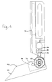
- each side wall 18 In the forward-facing edge regions 30 of each side wall 18, vertical grooves 32 are incorporated, which have an approximately C-shaped cross section, which can be seen in FIG. 4. In this way, a rear boundary surface 34 and two front clamping surfaces 36 are formed in the vertical groove 32. The lower end of each vertical groove 32 is open, but can be closed by a closing element, not shown.
- a thrust ring 38 which is mounted on the spindle 14 by means of a ball bearing, is used to guide an arcuate workpiece to be machined by means of the milling tool 16.
- a stop bar 40 is provided, the free, curved end 42 of which rests on the outer circumference of the stop ring 38.
- the stop bar 40 which can be made of plastic, has a slot-shaped recess 44 at its end opposite the free end 42 and is fastened in the vertical groove 32 on the right in FIGS. 1 and 2 by means of a clamping element 46.
- the clamping element 46 consists of a punch 48 with a mushroom-shaped head 50.
- the head 50 itself consists of two head parts 52 and 54 which can be displaced relative to one another, both of which are designed as circular disks.
- the head part 52 lying at the free end of the head is screwed firmly onto the free end of a rod 56 which is mounted so as to be longitudinally displaceable within the stamp 48.
- the diameter of the free end 58 of the rod 56 corresponds to the bore diameter of the punch 48 and thereby forms a collar on which a compression spring 60 is supported. This endeavors to always pull the rod 56 and with it the head part 52 into the release position.
- the free end 58 of the rod 56 is designed as a conical tip 62, which is pressed by the compression spring 60 against a wedge 64, which is mounted in a slot-like recess 66 of the plunger 48 so that it can be adjusted radially to the latter.
- the inclined surface of the wedge 64 opposite the tip 62 bears against a corresponding inclined surface of the recess 66.
- the wedge 64 can be moved with the aid of an adjusting screw 68 in the vertical direction in FIG.
- the wedge 64 displaces the rod 56 against the force of the compression spring 60, so that the head part 52 is moved away from the head part 54.
- Characterized the two head parts 52 and 54 are spread against the boundary surface 34 and the clamping surface 36 within the vertical groove 32, so that finally the clamping element 46 and with this the stop bar 40 are fixed.
- the punch 48 is also clamped within the recess 44. Since the threaded shaft 70 of the adjusting screw 68 extends through an elongated hole 72 machined into the stop bar 40, the stop bar 40 can be adjusted in its longitudinal direction.
- the latching body 74 engages again between the boundary edges of the vertical groove 32, so that the stop bar 40 is fixed in its rest position, for example when work is carried out without a stop ring 38.
- the latching body 74 thus ensures at least two defined positions of the stop bar 40.
Landscapes
- Life Sciences & Earth Sciences (AREA)
- Engineering & Computer Science (AREA)
- Mechanical Engineering (AREA)
- Wood Science & Technology (AREA)
- Forests & Forestry (AREA)
- Milling, Drilling, And Turning Of Wood (AREA)
- Chemical And Physical Treatments For Wood And The Like (AREA)
- Storage Of Harvested Produce (AREA)
Abstract
Description
Die Erfindung betrifft eine Anlaufleiste mit einem Klemmelement zur höhenverstellbaren Befestigung in einer im Querschnitt C-förmigen Vertikalnut einer Schutzhaube für Holzfräsmaschinen, wobei das Klemmelement einen Stempel mit einem pilzförmig erweiterten Kopf aufweist und mittels einer Stellschraube in der Vertikalnut festklemmbar ist.The invention relates to a stop bar with a clamping element for height-adjustable fastening in a cross-sectionally C-shaped vertical groove of a protective hood for wood milling machines, the clamping element having a plunger with a mushroom-shaped head and being clampable in the vertical groove by means of an adjusting screw.
Zum Abdecken eines an einer Spindel befestigten Fräswerkzeuges von Holzfräsmaschinen sind Schutzhauben bekannt, die aus zwei durch eine Rückwand miteinander verbundenen Seitenwänden, einem höhenverstellbaren, vorderen Schutzschild und einem Deckel bestehen, an dem eine Anschlußöffnung für eine Absaugvorrichtung vorgesehen ist. In die vorderen Kanten der Seitenwände sind Vertikalnuten eingearbeitet, die zur höhenverstellbaren Aufnahme einer Anlaufleiste oder dergleichen dienen.To cover a milling tool of wood milling machines attached to a spindle, protective hoods are known which consist of two side walls connected by a rear wall, a height-adjustable front protective shield and a cover on which a connection opening for a suction device is provided. In the front edges of the side walls, vertical grooves are incorporated, which are used for the height-adjustable reception of a stop bar or the like.
Eine Anlaufleiste der eingangs umrissenen Bauart ist in der DEOS 39 31 141 beschrieben und dargestellt. Bei dieser ist das Klemmelement ein in seiner Form nicht näher bezeichnetes Klemmstück, das über eine Schraube an einem Winkelstück gehalten wird. Nach Lösen der Schraube kann das Winkelstück in der Höhe verstellt werden, wobei das Klemmstück innerhalb der C-förmigen Nut gleitet. Wenn die gewünschte Höhe erreicht wird, muß die Schraube wieder festgezogen werden. Da diese im Bereich der Innenseite der Schutzhaube liegt, ist sie verhältnismäßig schwer zugänglich und kann nur nach Abnahme eines transparenten Schutzschildes betätigt werden. An dem waagrechten Schenkel des Winkelstücks ist mit Hilfe von zwei weiteren Schrauben die Anlaufleiste befestigt, welche nach Lösen der beiden Schrauben, die ebenfalls erst nach Abnahme des Schutzschildes zugänglich sind, nur in ihrer Längsrichtung verstellt werden kann. Die erläuterten Einstellungen können bei Fräswerkzeugen mit großem Durchmesser nur dann durchgeführt werden, wenn zuvor auch das Werkzeug ausgebaut worden ist, weil erst dann der nötige Zugang zu den innenliegenden Schrauben vorhanden ist. Bei Arbeiten mit einem Bogenfräsanschlag muß die Anlaufleiste abgeschraubt werden.A run-up bar of the type outlined at the beginning is described and illustrated in DEOS 39 31 141. In this case, the clamping element is a clamping piece, not specified in its shape, which is held on an angle piece by means of a screw. After loosening the screw, the angle piece can be adjusted in height, whereby the clamping piece slides within the C-shaped groove. When the desired height is reached, the screw must be tightened again. Since this is in the area of the inside of the protective hood, it is relatively difficult to access and can only be removed after removing a transparent one Protective shield are operated. On the horizontal leg of the contra-angle handpiece, the stop bar is fastened with the help of two further screws, which can only be adjusted in its longitudinal direction after loosening the two screws, which are also only accessible after removing the protective shield. The settings described can only be carried out for milling tools with a large diameter if the tool has also been removed beforehand, because only then is the necessary access to the internal screws available. When working with an arc milling stop, the stop bar must be unscrewed.
Trotz der beschriebenen, verhältnismäßig aufwendigen Befestigung der Anlaufleiste durch insgesamt drei Schrauben kann diese weder zum Fräswerkzeug hin bzw. von diesem weg geschwenkt werden, um eine Anpassung an unterschiedliche Werkkzeugdurchmesser zu erreichen, noch aus dem Arbeitsbereich herausgeschwenkt werden, wenn dies erforderlich sein sollte.Despite the described, relatively complex fastening of the stop bar by a total of three screws, it can neither be swiveled towards or away from the milling tool in order to adapt to different tool diameters, nor can it be swiveled out of the working area if this should be necessary.
Der Erfindung liegt die Aufgabe zugrunde, eine Anlaufleiste mit Klemmelement so auszubilden, daß diese mit einfachen, leicht zugänglichen Mitteln und ohne Zuhilfenahme von Werkzeugen verstellt und bei Bedarf in eine Ruhestellung gebracht werden kann, in der sie mit der Schutzhaube verbunden bleibt.The invention has for its object to design a stop bar with clamping element so that it can be adjusted with simple, easily accessible means and without the aid of tools and, if necessary, can be brought into a rest position in which it remains connected to the protective hood.
Bei einer Anlaufleiste der angegebenen Gattung wird diese Aufgabe erfindungsgemäß dadurch gelöst, daß der Kopf aus zwei mittels der Stellschraube gegeneinander verschiebbaren, gegen die Nutwände der Vertikalnut spreizbaren, kreisscheibenförmigen Kopfteilen besteht.In the case of a stop bar of the type specified, this object is achieved according to the invention in that the head consists of two circular disk-shaped head parts which can be displaced relative to one another by means of the adjusting screw and can be expanded against the groove walls of the vertical groove.
Diese Lösung hat den wesentlichen Vorteil, daß nach Lösen nur eines einzigen Bedienungselementes - der Stellschraube - wenigstens zwei Einstellvorgänge durchgeführt werden können, nämlich eine Höhenverstellung der Anlaufleiste und eine Schwenkung der Anlaufleiste nach oben. Die kreisscheibenförmigen Kopfteile gestatten nach Lösen der Stellschraube, daß die Anlaufleiste aus ihrer horizontalen Arbeitsstellung in eine vertikale Ruhestellung gedreht und dort wieder festgeklemmt werden kann, ohne von der Schutzhaube abgenommen werden zu müssen.
Um hierbei zwei definierte Leistenstellungen zu gewährleisten, ist an der zur Anlaufleiste gerichteten Unterseite des festen Kopfteils ein quadratischer Rastkörper ausgebildet, der in den jeweiligen Stellungen zwischen die Begrenzungskanten der Vertikalnut greift.This solution has the essential advantage that after loosening only a single control element - the set screw - at least two adjustment processes can be carried out, namely a height adjustment of the stop bar and a swiveling of the stop bar upwards. After loosening the set screw, the circular disk-shaped head parts allow the stop bar to come off their horizontal working position can be rotated into a vertical rest position and clamped there again without having to be removed from the protective hood.
In order to ensure two defined strip positions, a square locking body is formed on the underside of the fixed head part facing the stop strip, which engages in the respective positions between the boundary edges of the vertical groove.
Nach einer vorteilhaften Weiterbildung der Erfindung ist vorgesehen, daß der Stempel mittels der ein Langloch der Anlaufleiste durchgreifenden Stellschraube in einer Ausnehmung der Anlaufleiste verschoben und festgeklemmt werden kann. Damit wird der Vorteil erzielt, daß über die einzige Stellschraube eine weitere Einstellposition fixiert werden kann, nämlich die optimale Anstellung der Anlaufleiste an einen Anlaufring. Nach Lösen der Stellschraube kann nämlich die Anlaufleiste sowohl in Richtung des Langloches verschoben als auch um die Achse der Stellschraube verdreht werden.According to an advantageous development of the invention, it is provided that the stamp can be moved and clamped in a recess in the stop bar by means of the adjusting screw penetrating an elongated hole in the stop bar. This has the advantage that a further adjustment position can be fixed by means of the single adjusting screw, namely the optimal adjustment of the stop bar to a stop ring. After loosening the set screw, the run-up bar can both be moved in the direction of the elongated hole and rotated around the axis of the set screw.
Weitere Merkmale und Vorteile der Erfindung ergeben sich aus den Patentansprüchen. In der folgenden Beschreibung ist ein Ausführungsbeispiel erläutert, daß in der Zeichnung dargestellt ist. Es zeigen:
- Figur 1 die perspektivische Ansicht einer Schutzhaube für Holzfräsmaschinen, an der eine erfindungsgemäß ausgebildete Anlaufleiste angebracht ist,
- Figur 2 eine der Figur 1 entsprechende Darstellung, wobei die Anlaufleiste in ihre Ruhestellung hochgeschwenkt ist,
- Figur 3 eine Draufsicht der an eine der beiden Seitenwände der Schutzhaube angebauten Anlaufleiste,
- Figur 4 eine der Figur 3 entsprechende Darstellung, in der das Klemmelement gestrichelt zu erkennen ist, und
- Figur 5 eine aufgeschnittene, vordere Schrägansicht der Anlaufleiste zur Darstellung des Klemmelementes.
- FIG. 1 shows the perspective view of a protective hood for wood milling machines, to which a stop bar designed according to the invention is attached,
- FIG. 2 shows a representation corresponding to FIG. 1, the stop bar being pivoted up into its rest position,
- FIG. 3 shows a plan view of the stop bar attached to one of the two side walls of the protective hood,
- FIG. 4 shows a representation corresponding to FIG. 3, in which the clamping element can be seen in broken lines, and
- Figure 5 is a cut, front oblique view of the stop bar to show the clamping element.
In den Figuren 1 und 2 ist ein waagrechter Maschinentisch 10 einer Holzfräsmaschine angedeutet, auf dem eine Schutzhaube 12 fixiert ist, die den Arbeitsbereich eines an einer Spindel 14 angebrachten Fräswerkzeugs 16 abdeckt. Die Schutzhaube besteht aus zwei Seitenwänden 18, einer diese verbindenden Rückwand 20 und einem Deckel 22, der fest mit der Rückwand 20 verbunden ist. Von dem Deckel 22 steht nach vorn und seitlich ein Rand 24 nach unten ab, der im vorderen Bereich eine nach unten offene Aussparung 26 hat, welche die Sicht in das Innere der Schutzhaube 12 vergrößert. Der Deckel 22 hat in seinem hinteren Bereich einen Stutzen 28 für den Anschluß einer Absaugvorrichtung.1 and 2, a horizontal machine table 10 of a wood milling machine is indicated, on which a
In die nach vorn weisenden Kantenbereiche 30 jeder Seitenwand 18 sind Vertikalnuten 32 eingearbeitet, die einen etwa C-förmigen Querschnitt haben, der in Figur 4 zu erkennen ist. Auf diese Weise sind in der Vertikalnut 32 eine hintere Begrenzungsfläche 34 sowie zwei vordere Klemmflächen 36 gebildet. Das untere Ende jeder Vertikalnut 32 ist offen, kann jedoch durch ein nicht weiter dargestelltes Abschlußelement verschlossen werden.In the forward-facing
Zur Führung eines mittels des Fräswerkzeugs 16 zu bearbeitenden, bogenförmigen Werkstücks dient ein Anlaufring 38, der mittels eines Kugellagers auf der Spindel 14 gelagert ist. Um eine sichere Zuführung des zu bearbeitenden Werkstücks zum Fräswerkzeug 16 zu gewährleisten, ist eine Anlaufleiste 40 vorgesehen, deren freies, bogenförmiges Ende 42 am Außenumfang des Anlaufringes 38 anliegt. Die Anlaufleiste 40, die aus Kunststoff hergestellt werden kann, hat an ihrem dem freien Ende 42 gegenüberliegenden Ende eine schlitzförmige Ausnehmung 44 und ist mittels eines Klemmelementes 46 in der in den Figuren 1 und 2 rechten Vertikalnut 32 befestigt.A
Das Klemmelement 46 besteht aus einem Stempel 48 mit einem pilzförmig erweiterten Kopf 50. Der Kopf 50 selbst besteht aus zwei gegeneinander verschiebbaren Kopfteilen 52 und 54, die beide als kreisförmige Scheiben ausgebildet sind. Der am freien Ende des Kopfes liegende Kopfteil 52 ist auf das freie Ende einer Stange 56 fest aufgeschraubt, die innerhalb des Stempels 48 längsverschieblich gelagert ist. Wie Figur 5 zeigt, entspricht der Durchmesser des freien Endes 58 der Stange 56 dem Bohrungsdurchmesser des Stempels 48 und bildet dadurch einen Bund, an dem sich eine Druckfeder 60 abstützt. Diese ist bestrebt, die Stange 56 und mit dieser den Kopfteil 52 immer in die Lösestellung zu ziehen.The
Das freie Ende 58 der Stange 56 ist als konische Spitze 62 ausgebildet, die durch die Druckfeder 60 gegen einen Keil 64 gedrückt wird, der in einer langlochartigen Aussparung 66 des Stempels 48 radial zu diesem verstellbar gelagert ist. Dabei liegt die der Spitze 62 gegenüberliegende Schrägfläche des Keils 64 an einer entsprechenden Schrägfläche der Aussparung 66 an.The free end 58 of the
Der Keil 64 läßt sich mit Hilfe einer Stellschraube 68 in der in Figur 5 vertikalen Richtung bewegen. Bei der Bewegung nach oben verschiebt der Keil 64 die Stange 56 gegen die Kraft der Druckfeder 60, so daß der Kopfteil 52 vom Kopfteil 54 wegbewegt wird. Dadurch werden die beiden Kopfteile 52 und 54 gegen die Begrenzungsfläche 34 bzw. die Klemmfläche 36 innerhalb der Vertikalnut 32 gespreizt, so daß schließlich das Klemmelement 46 und mit diesem die Anlaufleiste 40 fixiert sind. In dieser Klemmstellung ist auch der Stempel 48 innerhalb der Ausnehmung 44 festgeklemmt. Da der Gewindeschaft 70 der Stellschraube 68 durch ein in die Anlaufleiste 40 eingearbeitetes Langloch 72 hindurchgreift, kann die Anlaufleiste 40 in ihrer Längsrichtung verstellt werden.The wedge 64 can be moved with the aid of an adjusting
Um die Anlaufleiste 40 aus ihrer in Figur 1 gezeigten Arbeitsstellung in die in Figur 2 dargestellten Ruhestellung hochzuklappen, genügt es, die Stellschraube 68 etwas zu lösen, damit die Druckfeder 60 die Stange 56 und mit dieser den Kopfteil 52 zurückziehen kann, bis ein an der Unterseite des Kopfteils 54 ausgebildeter, quadratischer Rastkörper 74 außer Eingriff mit den Begrenzungskanten der Vertikalnut 32 gebracht werden kann. Anschließend wird die Anlaufleiste 40 und mit dieser das Klemmelement 46 um 90° nach oben geschwenkt, worauf die Stellschraube 68 wieder festgezogen wird, bis die beiden Kopfteile 52 und 54 wieder in ihre gespreizte Stellung kommen. In dieser Stellung greift der Rastkörper 74 wieder zwischen die Begrenzungskanten der Vertikalnut 32, so daß die Anlaufleiste 40 in ihrer Ruhestellung fixiert ist, beispielsweise dann, wenn Arbeiten ohne Anlaufring 38 durchgeführt werden. Der Rastkörper 74 gewährleistet somit wenigstens zwei definierte Stellungen der Anlaufleiste 40.In order to fold up the run-
Claims (7)
- A guide bar with a clamping component for height adjustable fastening in a vertical groove - with a C shaped cross section - of a protective hood for wood shaping machines, the clamping component having a plunger with a head extended in a mushroom shape and lockable in the vertical groove by means of an adjusting screw, characterised in that the head (50) comprises two circular-disc head components (52, 54) displaceable towards each other by means of the adjusting screw (68), and able to be pushed apart towards the walls (34, 36) of the vertical groove (32).
- A guide bar according to Claim 1, characterised in that a square locking structure (74) for engaging between the boundary edges of the vertical groove (32) is formed on that lower side of the stationary head component (54) which is directed towards the guide rail (40).
- A guide bar according to Claim 1 or 2, characterised in that the plunger (48) is displaceable and lockable by means of the adjusting screw (68) which passes through an elongate hole (72) of the guide rail (40) and which is in a recess (44) of the guide rail (40).
- A guide rail according to any one of the preceding claims, characterised in that the head component (52) located at the free end of the head (50), is fastened at the end of a rod (56) mounted in the plunger (48) so as to be longitudinally displaceable .
- A guide rail according to Claim 4, characterised in that the end (58) of the rod (56) turned away from the head component (52) has an inclined surface (62) and rests on a wedge (64) radially adjustable inside the plunger (48).
- A guide rail according to Claim 4 or 5, characterised in that the rod (56) is pulled by means of a spring (60) in the direction of the release position.
- A guide rail according to Claim 5 or 6, characterised in that the adjusting screw (68) is screwed into a tapped hole of the wedge (64).
Applications Claiming Priority (3)
| Application Number | Priority Date | Filing Date | Title |
|---|---|---|---|
| DE4238449 | 1992-11-13 | ||
| DE4238449A DE4238449C1 (en) | 1992-11-13 | 1992-11-13 | Stop bar for a protective hood on wood milling machines |
| PCT/EP1993/002943 WO1994011641A1 (en) | 1992-11-13 | 1993-10-25 | Guide bar for the protective hood of wood shaping machines |
Publications (2)
| Publication Number | Publication Date |
|---|---|
| EP0621926A1 EP0621926A1 (en) | 1994-11-02 |
| EP0621926B1 true EP0621926B1 (en) | 1996-01-17 |
Family
ID=6472858
Family Applications (1)
| Application Number | Title | Priority Date | Filing Date |
|---|---|---|---|
| EP93924045A Expired - Lifetime EP0621926B1 (en) | 1992-11-13 | 1993-10-25 | Guide bar for the protective hood of wood shaping machines |
Country Status (8)
| Country | Link |
|---|---|
| US (1) | US5555921A (en) |
| EP (1) | EP0621926B1 (en) |
| JP (1) | JPH07502948A (en) |
| AT (1) | ATE133237T1 (en) |
| DE (2) | DE4238449C1 (en) |
| DK (1) | DK0621926T3 (en) |
| ES (1) | ES2085173T3 (en) |
| WO (1) | WO1994011641A1 (en) |
Families Citing this family (6)
| Publication number | Priority date | Publication date | Assignee | Title |
|---|---|---|---|---|
| CH689971A5 (en) * | 1994-05-04 | 2000-02-29 | Bobst Sa | Device for centering and locking a tool-supporting frame in a cutting press. |
| EP0805007B1 (en) * | 1996-05-04 | 2000-01-26 | AIGNER, Georg | Guide bar |
| DE19617888C1 (en) * | 1996-05-04 | 1997-01-02 | Georg Aigner | Approach strip with clamp component |
| DE19701880C2 (en) * | 1997-01-21 | 1999-10-21 | Fried Kunststofftechnik Gmbh | Chip collecting device |
| DE19900430C1 (en) * | 1999-01-08 | 2000-07-20 | Georg Aigner | Protective hood for wood milling machines |
| US20080078471A1 (en) * | 2006-09-28 | 2008-04-03 | Eastway Fair Company Limited | Fence assembly with articulating bit guard |
Family Cites Families (10)
| Publication number | Priority date | Publication date | Assignee | Title |
|---|---|---|---|---|
| US1947885A (en) * | 1933-06-19 | 1934-02-20 | Delta Mfg Co | Work guide |
| US2104158A (en) * | 1935-05-02 | 1938-01-04 | Duro Metal Prod Co | Work guide for woodworking machines |
| FR2348012A1 (en) * | 1976-04-14 | 1977-11-10 | Nanini Antoine | Connection for fixing work piece to machine tool table - is mounted in groove in table and anchored by two cramp irons |
| US4547092A (en) * | 1984-02-21 | 1985-10-15 | Hamilton Industries | Accessory clamp for medical table |
| DE3444621A1 (en) * | 1984-12-07 | 1986-06-19 | A. Römheld GmbH & Co KG, 6312 Laubach | Fastening element for clamping tools and pallets to machine tables |
| AT385444B (en) * | 1985-07-16 | 1988-03-25 | Straka Roman | Work-holding fixture |
| DE8915933U1 (en) * | 1989-09-19 | 1992-04-09 | Fried Kunststofftechnik GmbH, 7068 Urbach | Chip catcher for a table milling machine |
| US5117880A (en) * | 1990-10-16 | 1992-06-02 | Delta International Machinery Corporation | Shield for cutting blade |
| DE4131943C1 (en) * | 1991-09-25 | 1992-09-17 | Georg 8386 Reisbach De Aigner | |
| DE4339953A1 (en) * | 1993-11-24 | 1995-06-01 | Weinig Michael Ag | Machine for processing workpieces made of wood, plastic and the like |
-
1992
- 1992-11-13 DE DE4238449A patent/DE4238449C1/en not_active Expired - Fee Related
-
1993
- 1993-10-25 ES ES93924045T patent/ES2085173T3/en not_active Expired - Lifetime
- 1993-10-25 DE DE59301476T patent/DE59301476D1/en not_active Expired - Fee Related
- 1993-10-25 WO PCT/EP1993/002943 patent/WO1994011641A1/en active IP Right Grant
- 1993-10-25 AT AT93924045T patent/ATE133237T1/en not_active IP Right Cessation
- 1993-10-25 US US08/244,801 patent/US5555921A/en not_active Expired - Fee Related
- 1993-10-25 DK DK93924045.3T patent/DK0621926T3/en active
- 1993-10-25 EP EP93924045A patent/EP0621926B1/en not_active Expired - Lifetime
- 1993-10-25 JP JP6511641A patent/JPH07502948A/en active Pending
Also Published As
| Publication number | Publication date |
|---|---|
| US5555921A (en) | 1996-09-17 |
| JPH07502948A (en) | 1995-03-30 |
| ATE133237T1 (en) | 1996-02-15 |
| EP0621926A1 (en) | 1994-11-02 |
| DE59301476D1 (en) | 1996-02-29 |
| WO1994011641A1 (en) | 1994-05-26 |
| DE4238449C1 (en) | 1994-03-24 |
| ES2085173T3 (en) | 1996-05-16 |
| DK0621926T3 (en) | 1996-03-18 |
Similar Documents
| Publication | Publication Date | Title |
|---|---|---|
| DE102005009227A1 (en) | Router tool work bench has central aperture with a flange fixture for drive mechanism and router tool | |
| EP0558692B1 (en) | Protective and guiding device for wood shaping machines | |
| EP0621926B1 (en) | Guide bar for the protective hood of wood shaping machines | |
| EP0598079B1 (en) | Safety hood for wood shaping machines | |
| DE7825793U1 (en) | METAL WORKING MACHINE | |
| DE4406597A1 (en) | Adjustable wall cutting attachment | |
| EP0533093A2 (en) | Continuously variable clamping device | |
| DE19845386A1 (en) | Punch for machine tool has each pressure part intended for side support against clamping device | |
| DE29521059U1 (en) | Fitting for mounting and aligning a front panel on a drawer or the like. | |
| EP0805007B1 (en) | Guide bar | |
| DE1477355A1 (en) | Tool holder for cutting tools | |
| DE29902343U1 (en) | Grinding device for drills | |
| DE9014657U1 (en) | Grooving machine | |
| DE3930682A1 (en) | GUIDE TABLE FOR PORTABLE MILLING MACHINES | |
| EP1306504B1 (en) | Holding device fo a door stop hinge flap adjustable in a door thickness or transversal direction on a hollow profile, such as an aluminium profile | |
| DE3637485C2 (en) | ||
| DE19739269C1 (en) | Machine tool clamping table | |
| WO1988005359A1 (en) | Device for joining two components essentially dynamically balanced in the joining zone, in particular a tool head with a tool holder in machine-tools | |
| DE3431110C2 (en) | ||
| DE828035C (en) | Machine for reworking mass-produced parts, especially for slotting screws | |
| DE7227912U (en) | Stamping tool holder on stamping presses | |
| DE29810720U1 (en) | Jaw holder | |
| EP0570605B1 (en) | Guard for planing machine | |
| DE2534378B2 (en) | Device for the non-positive connection of a swiveling plaster model carrier with a base plate carrying the motor housing of a sawing machine | |
| DE102007023783B3 (en) | Surface milling cutter has supporting table on which a workpiece is fixed and has passage recess, from which guide columns protrude, on which downward projecting and passage recess gripping milling head is slidably guided |
Legal Events
| Date | Code | Title | Description |
|---|---|---|---|
| PUAI | Public reference made under article 153(3) epc to a published international application that has entered the european phase |
Free format text: ORIGINAL CODE: 0009012 |
|
| 17P | Request for examination filed |
Effective date: 19940614 |
|
| AK | Designated contracting states |
Kind code of ref document: A1 Designated state(s): AT BE CH DE DK ES FR GB GR IE IT LI LU MC NL PT SE |
|
| 17Q | First examination report despatched |
Effective date: 19950216 |
|
| GRAA | (expected) grant |
Free format text: ORIGINAL CODE: 0009210 |
|
| AK | Designated contracting states |
Kind code of ref document: B1 Designated state(s): AT BE CH DE DK ES FR GB GR IE IT LI LU MC NL PT SE |
|
| PG25 | Lapsed in a contracting state [announced via postgrant information from national office to epo] |
Ref country code: GR Free format text: LAPSE BECAUSE OF FAILURE TO SUBMIT A TRANSLATION OF THE DESCRIPTION OR TO PAY THE FEE WITHIN THE PRESCRIBED TIME-LIMIT Effective date: 19960117 |
|
| REF | Corresponds to: |
Ref document number: 133237 Country of ref document: AT Date of ref document: 19960215 Kind code of ref document: T |
|
| REG | Reference to a national code |
Ref country code: IE Ref legal event code: FG4D Free format text: 66966 |
|
| REF | Corresponds to: |
Ref document number: 59301476 Country of ref document: DE Date of ref document: 19960229 |
|
| REG | Reference to a national code |
Ref country code: DK Ref legal event code: T3 |
|
| GBT | Gb: translation of ep patent filed (gb section 77(6)(a)/1977) |
Effective date: 19960220 |
|
| REG | Reference to a national code |
Ref country code: CH Ref legal event code: NV Representative=s name: AMMANN PATENTANWAELTE AG BERN |
|
| ITF | It: translation for a ep patent filed | ||
| ET | Fr: translation filed | ||
| REG | Reference to a national code |
Ref country code: ES Ref legal event code: FG2A Ref document number: 2085173 Country of ref document: ES Kind code of ref document: T3 |
|
| SC4A | Pt: translation is available |
Free format text: 960417 AVAILABILITY OF NATIONAL TRANSLATION |
|
| PG25 | Lapsed in a contracting state [announced via postgrant information from national office to epo] |
Ref country code: IE Free format text: LAPSE BECAUSE OF NON-PAYMENT OF DUE FEES Effective date: 19960815 |
|
| REG | Reference to a national code |
Ref country code: IE Ref legal event code: FD4D Ref document number: 66966 Country of ref document: IE |
|
| PG25 | Lapsed in a contracting state [announced via postgrant information from national office to epo] |
Ref country code: LU Free format text: LAPSE BECAUSE OF NON-PAYMENT OF DUE FEES Effective date: 19961031 |
|
| PLBE | No opposition filed within time limit |
Free format text: ORIGINAL CODE: 0009261 |
|
| STAA | Information on the status of an ep patent application or granted ep patent |
Free format text: STATUS: NO OPPOSITION FILED WITHIN TIME LIMIT |
|
| 26N | No opposition filed | ||
| PG25 | Lapsed in a contracting state [announced via postgrant information from national office to epo] |
Ref country code: MC Effective date: 19970430 |
|
| PGFP | Annual fee paid to national office [announced via postgrant information from national office to epo] |
Ref country code: AT Payment date: 19970926 Year of fee payment: 5 |
|
| PGFP | Annual fee paid to national office [announced via postgrant information from national office to epo] |
Ref country code: DK Payment date: 19971028 Year of fee payment: 5 |
|
| PGFP | Annual fee paid to national office [announced via postgrant information from national office to epo] |
Ref country code: NL Payment date: 19971031 Year of fee payment: 5 Ref country code: ES Payment date: 19971031 Year of fee payment: 5 |
|
| PG25 | Lapsed in a contracting state [announced via postgrant information from national office to epo] |
Ref country code: DK Free format text: LAPSE BECAUSE OF NON-PAYMENT OF DUE FEES Effective date: 19981025 Ref country code: AT Free format text: LAPSE BECAUSE OF NON-PAYMENT OF DUE FEES Effective date: 19981025 |
|
| PG25 | Lapsed in a contracting state [announced via postgrant information from national office to epo] |
Ref country code: ES Free format text: LAPSE BECAUSE OF NON-PAYMENT OF DUE FEES Effective date: 19981026 |
|
| PG25 | Lapsed in a contracting state [announced via postgrant information from national office to epo] |
Ref country code: NL Free format text: LAPSE BECAUSE OF NON-PAYMENT OF DUE FEES Effective date: 19990501 |
|
| NLV4 | Nl: lapsed or anulled due to non-payment of the annual fee |
Effective date: 19990501 |
|
| PGFP | Annual fee paid to national office [announced via postgrant information from national office to epo] |
Ref country code: SE Payment date: 19991027 Year of fee payment: 7 |
|
| PGFP | Annual fee paid to national office [announced via postgrant information from national office to epo] |
Ref country code: PT Payment date: 20000922 Year of fee payment: 8 |
|
| PGFP | Annual fee paid to national office [announced via postgrant information from national office to epo] |
Ref country code: BE Payment date: 20001002 Year of fee payment: 8 |
|
| PGFP | Annual fee paid to national office [announced via postgrant information from national office to epo] |
Ref country code: GB Payment date: 20001025 Year of fee payment: 8 |
|
| PG25 | Lapsed in a contracting state [announced via postgrant information from national office to epo] |
Ref country code: SE Free format text: THE PATENT HAS BEEN ANNULLED BY A DECISION OF A NATIONAL AUTHORITY Effective date: 20001030 |
|
| PGFP | Annual fee paid to national office [announced via postgrant information from national office to epo] |
Ref country code: CH Payment date: 20001130 Year of fee payment: 8 |
|
| EUG | Se: european patent has lapsed |
Ref document number: 93924045.3 |
|
| PG25 | Lapsed in a contracting state [announced via postgrant information from national office to epo] |
Ref country code: GB Free format text: LAPSE BECAUSE OF NON-PAYMENT OF DUE FEES Effective date: 20011025 |
|
| PG25 | Lapsed in a contracting state [announced via postgrant information from national office to epo] |
Ref country code: LI Free format text: LAPSE BECAUSE OF NON-PAYMENT OF DUE FEES Effective date: 20011031 Ref country code: CH Free format text: LAPSE BECAUSE OF NON-PAYMENT OF DUE FEES Effective date: 20011031 Ref country code: BE Free format text: LAPSE BECAUSE OF NON-PAYMENT OF DUE FEES Effective date: 20011031 |
|
| REG | Reference to a national code |
Ref country code: GB Ref legal event code: IF02 |
|
| BERE | Be: lapsed |
Owner name: AIGNER GEORG Effective date: 20011031 |
|
| PG25 | Lapsed in a contracting state [announced via postgrant information from national office to epo] |
Ref country code: PT Free format text: LAPSE BECAUSE OF NON-PAYMENT OF DUE FEES Effective date: 20020430 |
|
| GBPC | Gb: european patent ceased through non-payment of renewal fee |
Effective date: 20011025 |
|
| REG | Reference to a national code |
Ref country code: CH Ref legal event code: PL |
|
| REG | Reference to a national code |
Ref country code: PT Ref legal event code: MM4A Free format text: LAPSE DUE TO NON-PAYMENT OF FEES Effective date: 20020430 |
|
| PGFP | Annual fee paid to national office [announced via postgrant information from national office to epo] |
Ref country code: FR Payment date: 20021011 Year of fee payment: 10 |
|
| REG | Reference to a national code |
Ref country code: ES Ref legal event code: FD2A Effective date: 19991113 |
|
| PG25 | Lapsed in a contracting state [announced via postgrant information from national office to epo] |
Ref country code: FR Free format text: LAPSE BECAUSE OF NON-PAYMENT OF DUE FEES Effective date: 20040630 |
|
| REG | Reference to a national code |
Ref country code: FR Ref legal event code: ST |
|
| PGFP | Annual fee paid to national office [announced via postgrant information from national office to epo] |
Ref country code: IT Payment date: 20061031 Year of fee payment: 14 |
|
| PGFP | Annual fee paid to national office [announced via postgrant information from national office to epo] |
Ref country code: DE Payment date: 20071224 Year of fee payment: 15 |
|
| PG25 | Lapsed in a contracting state [announced via postgrant information from national office to epo] |
Ref country code: IT Free format text: LAPSE BECAUSE OF NON-PAYMENT OF DUE FEES Effective date: 20071025 Ref country code: DE Free format text: LAPSE BECAUSE OF NON-PAYMENT OF DUE FEES Effective date: 20090501 |