EP0621463B1 - A pneumatic transport system for powdered materials - Google Patents
A pneumatic transport system for powdered materials Download PDFInfo
- Publication number
- EP0621463B1 EP0621463B1 EP94105892A EP94105892A EP0621463B1 EP 0621463 B1 EP0621463 B1 EP 0621463B1 EP 94105892 A EP94105892 A EP 94105892A EP 94105892 A EP94105892 A EP 94105892A EP 0621463 B1 EP0621463 B1 EP 0621463B1
- Authority
- EP
- European Patent Office
- Prior art keywords
- transport
- transport pipe
- plug
- guide plate
- powdered
- Prior art date
- Legal status (The legal status is an assumption and is not a legal conclusion. Google has not performed a legal analysis and makes no representation as to the accuracy of the status listed.)
- Expired - Lifetime
Links
Images





Classifications
-
- B—PERFORMING OPERATIONS; TRANSPORTING
- B65—CONVEYING; PACKING; STORING; HANDLING THIN OR FILAMENTARY MATERIAL
- B65G—TRANSPORT OR STORAGE DEVICES, e.g. CONVEYORS FOR LOADING OR TIPPING, SHOP CONVEYOR SYSTEMS OR PNEUMATIC TUBE CONVEYORS
- B65G53/00—Conveying materials in bulk through troughs, pipes or tubes by floating the materials or by flow of gas, liquid or foam
- B65G53/34—Details
- B65G53/40—Feeding or discharging devices
- B65G53/46—Gates or sluices, e.g. rotary wheels
- B65G53/4683—Gates or sluices, e.g. rotary wheels with a reciprocating mover acting directly on material
-
- B—PERFORMING OPERATIONS; TRANSPORTING
- B65—CONVEYING; PACKING; STORING; HANDLING THIN OR FILAMENTARY MATERIAL
- B65G—TRANSPORT OR STORAGE DEVICES, e.g. CONVEYORS FOR LOADING OR TIPPING, SHOP CONVEYOR SYSTEMS OR PNEUMATIC TUBE CONVEYORS
- B65G53/00—Conveying materials in bulk through troughs, pipes or tubes by floating the materials or by flow of gas, liquid or foam
- B65G53/34—Details
- B65G53/40—Feeding or discharging devices
- B65G53/46—Gates or sluices, e.g. rotary wheels
- B65G53/4691—Gates or sluices, e.g. rotary wheels of air-lock type, i.e. at least two valves opening asynchronously
-
- G—PHYSICS
- G01—MEASURING; TESTING
- G01F—MEASURING VOLUME, VOLUME FLOW, MASS FLOW OR LIQUID LEVEL; METERING BY VOLUME
- G01F11/00—Apparatus requiring external operation adapted at each repeated and identical operation to measure and separate a predetermined volume of fluid or fluent solid material from a supply or container, without regard to weight, and to deliver it
- G01F11/28—Apparatus requiring external operation adapted at each repeated and identical operation to measure and separate a predetermined volume of fluid or fluent solid material from a supply or container, without regard to weight, and to deliver it with stationary measuring chambers having constant volume during measurement
- G01F11/284—Apparatus requiring external operation adapted at each repeated and identical operation to measure and separate a predetermined volume of fluid or fluent solid material from a supply or container, without regard to weight, and to deliver it with stationary measuring chambers having constant volume during measurement combined with electric level detecting means
-
- G—PHYSICS
- G01—MEASURING; TESTING
- G01F—MEASURING VOLUME, VOLUME FLOW, MASS FLOW OR LIQUID LEVEL; METERING BY VOLUME
- G01F11/00—Apparatus requiring external operation adapted at each repeated and identical operation to measure and separate a predetermined volume of fluid or fluent solid material from a supply or container, without regard to weight, and to deliver it
- G01F11/28—Apparatus requiring external operation adapted at each repeated and identical operation to measure and separate a predetermined volume of fluid or fluent solid material from a supply or container, without regard to weight, and to deliver it with stationary measuring chambers having constant volume during measurement
- G01F11/30—Apparatus requiring external operation adapted at each repeated and identical operation to measure and separate a predetermined volume of fluid or fluent solid material from a supply or container, without regard to weight, and to deliver it with stationary measuring chambers having constant volume during measurement with supply and discharge valves of the lift or plug-lift type
- G01F11/34—Apparatus requiring external operation adapted at each repeated and identical operation to measure and separate a predetermined volume of fluid or fluent solid material from a supply or container, without regard to weight, and to deliver it with stationary measuring chambers having constant volume during measurement with supply and discharge valves of the lift or plug-lift type for fluent solid material
-
- G—PHYSICS
- G01—MEASURING; TESTING
- G01F—MEASURING VOLUME, VOLUME FLOW, MASS FLOW OR LIQUID LEVEL; METERING BY VOLUME
- G01F11/00—Apparatus requiring external operation adapted at each repeated and identical operation to measure and separate a predetermined volume of fluid or fluent solid material from a supply or container, without regard to weight, and to deliver it
- G01F11/28—Apparatus requiring external operation adapted at each repeated and identical operation to measure and separate a predetermined volume of fluid or fluent solid material from a supply or container, without regard to weight, and to deliver it with stationary measuring chambers having constant volume during measurement
- G01F11/36—Apparatus requiring external operation adapted at each repeated and identical operation to measure and separate a predetermined volume of fluid or fluent solid material from a supply or container, without regard to weight, and to deliver it with stationary measuring chambers having constant volume during measurement with supply or discharge valves of the rectilinearly-moved slide type
- G01F11/40—Apparatus requiring external operation adapted at each repeated and identical operation to measure and separate a predetermined volume of fluid or fluent solid material from a supply or container, without regard to weight, and to deliver it with stationary measuring chambers having constant volume during measurement with supply or discharge valves of the rectilinearly-moved slide type for fluent solid material
Definitions
- the present invention relates to a pneumatic transport system for powdered or granular materials for transporting powdered or granular materials such as tablets or resin pellets to a desired place by utilizing a transport plug which is pneumatically transferred in a transport pipe.
- a transport plug 4e is provided in a transport pipe 3e for transporting tablets and is pneumatically transported to a material discharge port 10e by air pressure supplied to the transport pipe 3e from a nozzle 9.
- tablets A are sequentially filled in the material weighing chamber 62 when the valve plug 6e closes the bottom of the chamber 62.
- the slide damper 61 is moved. Tablets are prevented from falling into the material weighing chamber 62 by the slide damper 61 and the inclined guide plate 60.
- the tablets A are quantified in the material chamber 62 and housed in the transport plug 4e by opening the valve plug 6e, enabling quantitative transportation of tablets.
- Such a prior system has the following problems because the sensor S is used to weigh the tablets A .
- GB-A-677 542 relates to the measuring of loose materials and may be employed in association with other handling or conveying mechanism, or it can be used separately as a convenient and improved means of determining a required amount of loose material or substance.
- an inclined guide plate and a slide damper are provided in a material feeder and are used for stopping feeding of powdered or granular materials.
- materials are filled over an inclined guide plate and a slide damper and weighed or quantified by being blocked by the slide damper.
- materials aren't damaged when they are blocked by the slide damper because an escaping space is formed under the inclined guide plate by the slide damper.
- the present invention has such unique advantage which isn't seen in the prior art.
- the slide damper slides from the opposite side of the inclined guide plate into the escaping space formed under the inclined guide plate so that powdered or granular materials are divided vertically and some materials move into the escaping space.
- the material feeder is inclined at a specific angle so that the escaping space can be enlarged.
- the valve is reciprocatably provided in a communication passage of which one end is communicated with the material supply port of the transport pipe and an upper wall is communicated with the bottom opening of the material feeder. The bottom opening is closed when the valve moves forward to close the supply port of the transport pipe.
- the valve plug is reciprocatably provided in a communication passage of which bottom end is connected with the material supply port of the transport pipe so as to be able to open and close the material supply port, an inner wall of the communication passage is opened so as to communicate with the bottom opening of the material feeder, and the bottom opening of the material feeder is closed by a peripheral side of the valve plug when the valve plug moves forward.
- air discharge means is provided at the tip of the valve plug and blows away the powdered or granular materials remaining in the communication passage into the plug setting portion through the material supply port by air pressure.
- the transport pipe is slanted in such a manner that a material discharge port is located higher than the material supply port and the pipe is provided with gas supply means for pneumatically transporting a transport plug set in the plug setting portion under the material supply port upward to the material discharge port.
- Disc-like bodies of the transport plug may be provided with plural through holes for passing air beneath the transport plug into the area above it when the transport plug falls under gravity in the transport pipe after the transport plug is pneumatically transported into the material discharge port.
- the present pneumatic transport system for powdered or granular materials materials are sequentially fed in the material feeder and filled over the inclined guide plate with the bottom opening of the feeder closed by the valve plug.
- the escaping space in which the materials aren't filled is formed under the inclined guide plate.
- the capacity of the escaping space depends on the diameter, shape and surface condition of a particle of the materials.
- powdered or granular materials have such characteristic that they are stably stored at an inherent angle of repose under the inclined guide plate. Therefore, the escaping space of the same capacity is always formed under the inclined guide plate if the materials consist of the same kind of powder or granule.
- the materials filled under the slide damper is quantified when the slide damper is operated to be moved in the material feeder below the inclined guide plate and divides the materials in the feeder vertically with some materials moved in the escaping space.
- the materials can be quantitatively transported when the bottom opening of the material feeder is opened so that the materials are stored in the transport plug housed under the slide damper. Therefore, a sensor for weighing the materials isn't required to quantify the materials.
- the slide damper can't usually separate the materials in the feeder because of existence and resistance of the powdered or granular materials.
- the escaping space is formed in the material feeder and the materials can suitably flow in the feeder. Therefore, the materials in the material feeder can be prevented as much as possible from being the hindrance to the operation of the slide damper because the materials flow in accordance with the operation of the slide damper and some of them move into the escaping space when they are divided by the slide damper in the feeder. Accordingly, the slide damper can appropriately divide the materials in the material feeder.
- the slide damper slides from the opposite side of the inclined guide plate into the escaping space formed under the inclined guide plate. Then the slide damper divides the materials vertically with some materials pushed into the escaping space. As the result, the materials aren't pressed nor pinched by the slide damper. Even if the materials are fragile tablets, improper breakage isn't caused.
- the material feeder is provided so as to be inclined with a fixed angle and the capacity of the escaping space under the inclined guide plate can be enlarged. Therefore, the materials are more completely prevented from being damaged when the slide damper slides in the material feeder, because the materials can easily run in the feeder in accordance with the operation of the slide damper.
- one valve plug can open and close both the material supply port of the transport pipe and the bottom opening of the material feeder.
- Compressed gas in the transport pipe for pneumatic transportation doesn't leak into the bottom opening of the material feeder because the valve plug blocks up both of them airtightly.
- no space is required for the valve plug in the material feeder because the valve plug isn't provided in the material feeder. Accordingly, the material feeder can be made smaller by reducing its height, if necessary.
- the powdered or granular materials discharged from the bottom opening of the material feeder remain in the communication passage provided on the material supply port, such materials can be blown away into the plug setting portion of the transport pipe from the material supply port by air pressure supplied form air discharge means provided at the tip of the valve plug. Therefore, the materials remaining in the communication passage can be prevented from being pinched and damaged by the valve plug.
- transport gas is stopped feeding after the transport plug is pneumatically transported into the material discharge port which is located higher than the material supply port.
- the transport plug falls under gravity and spontaneously returns to the plug setting portion where the transport plug is originally housed. Therefore, gas supply means for returning the transport plug isn't required, thereby simplifying the system.
- the air beneath the transport plug in the transport pipe passes the through holes of its bodies into the area above it when the transport plug falls under gravity. Because air resistance on the transport plug is reduced, its falling speed can be increased and the time which it takes to return to its original housing position can be shortened.
- the present invention as defined by claims 1 to 4 comprises a pneumatic transport system with a material feeder which is integrally provided with a transport pipe for transferring the powdered material by a transport plug in the transport pipe.
- the material feeder comprises at a bottom thereof a valve for opening and closing a bottom opening and inside a slide damper and an inclined guide plate both facing each other.
- the bottom communicates with a material supply port of the transport pipe through the bottom opening.
- the inclined guide plate is formed with an escaping space where material is not filled during the charging of powdered material into the material feeder with the bottom opening kept closed by the valve.
- the slide damper is projected under the inclined guide plate so that some of the powdered material is so entered into the escaping space during the charging of the material into the material feeder over a level of the guide plate.
- the powdered material charged in the material feeder is divided into two blocks for measuring when the slide damper is closed.
- the transport plug is constructed such that it moves reciprocatively up and down in the transport pipe and receives measured powdered material from the material feeder by opening the valve during the transport plug remains at its waiting position below in the transport pipe. Then the valve is closed and thereafter the transport plug moves up in the transport plug by a pressurized gas fed into said transport pipe and discharges powdered material at a material discharge port provided above in the transport pipe, whereby powdered material is repeatedly transported by the transport plug by a measured amount.
- Fig.1 is one embodiment of a pneumatic transport system for powdered or granular materials according to the present invention.
- Fig.2 is a perspective view of a transport plug used for a pneumatic transport system for powdered or granular materials according to the present invention.
- Fig.3 is a sectional view showing how a valve plug is installed.
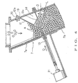
- Fig.4 is a section showing how an inclined guide plate and a slide damper are provided for a material feeder.
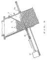
- Fig.5 is a sectional view of one embodiment showing how a slide damper divides an inside of a material feeder vertically.
- Fig.6 is a sectional view of one embodiment showing how powdered or granular materials stored in a material feeder are fed into a transport plug.
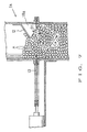
- Fig.7 is a partial sectional view of other embodiment of the material feeder.
- Fig.8 is a sectional view showing one embodiment of a prior art of a pneumatic transport system for powdered or granular materials.
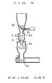
- Fig.9 is a sectional view showing how the pneumatic transport system of Fig.8 is operated.
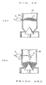
- Fig.10(a) and (b) are partial sectional views of one embodiment of material weighing means according to a prior art.
- Fig.1 is a sectional view showing the overall construction of a pneumatic transport system for powdered or granular materials according to the present invention.
- the pneumatic transport system pneumatically transports tablets A discharged from a pipe 50a of a tablet molding machine 50, which manufactures tablets, to a collector 51.
- the pneumatic transport system comprises a transport pipe 3 which is formed integrally with pipes 1a, 1b made of synthetic resin and so on and a penetrated passage 3a provided for a fitting 2, a transport plug 4 housed in a plug setting portion 1c of the transport pipe 3, a valve plug 6 for opening and closing a material supply port 5, a material feeder 7 provided above the material supply port 5, an inclined guide plate 12 provided in the material feeder 7, and a slide damper 13.
- the fitting 2 constituting one part of the transport pipe 3 is designed to be supported by a cart 11 so as to be easily carried.
- the transport pipe 3 is formed integrally like a straight pipe and inclined such that a terminal end 3B is located higher than an initial end 3A.
- the present invention isn't restricted to this construction and the transport pipe 3 may be curved or provided horizontally.
- An air nozzle 9 connected with a compressor 8 is provided at the initial end 3A of the transport pipe 3.
- the transport plug 4 can be pneumatically transported to the material discharge port 10 provided at the terminal end 3B of the transport pipe 3 by supplying compressed air into the transport pipe 3 from the air nozzle 9, shown as an arrow B with a broken line in Fig.1.
- Compressed air may be actively supplied for descending the transport plug 4 or suction means may be operated in order to return the transport plug 4 into the plug setting portion 1c after it is pneumatically transported to the material discharge port 10. Otherwise, the system may be constructed such that the transport plug 4 descends in the inclined transport pipe 3 under gravity.
- One embodiment of the transport plug 4 is constructed such that three disc-like bodies 40a, 40b, 40c are connected with a connecting rod 41 each other and spaces 43, 43a for storing powdered or granular materials are formed between each bodies 40a, 40b, 40c.
- Each bodies 40a, 40b, 40c are provided with penetrated holes 42. According to such a construction, the air in the transport pipe 3 passes through each holes 42 and air resistance on the transport plug 4 is reduced when the transport plug 4 is returned downwardly under gravity from the material discharge port 10. Therefore, its returning speed can be increased.
- the valve plug 6, a piston type plug, is provided in a communication passage 14 of which one end is opened as the material supply port 5, as shown in Fig.3.
- the valve plug 6 can be reciprocated back and forward by an air cylinder 15 and the material supply port 5 can be opened and closed by the tip of the valve plug 6.
- the material feeder 7 is provided above the communication passage 14 and its bottom opening 70 is communicated with the material supply port 5 of the transport pipe 3.
- the bottom opening 70 is opened at the same time that the material supply port 5 is opened by retracting the valve plug 6 as shown in Fig.3 and communicated to the transport pipe 3 via the communication passage 14.
- the bottom opening 70 is closed by the circumferential side of the valve plug 6 when the valve plug 6 closes the material supply port 5 as shown in Fig.1.
- An air discharge port 16 is provided at a lower side of the tip of the valve plug 6.
- the air discharge port 16 is provided for discharging compressed air forward of the valve plug 6. Compressed air is supplied from an air pipe 17 connected at the rear of the valve plug 6.
- the material feeder 7 is comprised of pipe members 7a, 7b which form a passage through which tablets A are supplied from the pipe 50a of the tablet molding machine 50.
- the feeder 7 is designed so as to be inclined at an appropriate angle (for example about 30 degrees) so as to have enough capacity for an escaping space 18.
- the inclined guide plate 12, a flat plate with an opening 13a, is provided so as to be inclined downwardly from one side of the upper inner wall of the material feeder 7.
- the inclined guide plate 12 is provided for producing the escaping space 18 under which the tablets A aren't filled even if the tablets A are fed at the level exceeding the guide plate 12, as shown in Fig.4.
- the inclined guide plate 12 is installed in such a manner that a support shaft 12a projecting at the back of the guide plate 12 penetrates a long hole 19 of the pipe member 7a to be supported by a nut 20, enabling its mounting height to be adjusted up and down by loosening the nut 20. Otherwise, the inclined angle of the guide plate 12 is preferably adjusted at random (not shown).
- the slide damper 13 is formed like a thin plate and provided between the pipe members 7a and 7b.
- the slide damper 13 is moved perpendicularly to the material feed by driving an air cylinder 21 so as to interrupt material feeding.
- the slide damper 13 has the opening 13a and is provided below the inclined guide plate 12 and moves from the opposite side of where the inclined guide plate 12 is attached toward the escaping space like an arrow D .
- the tablets A manufactured by the tablet molding machine 50 are sequentially fed into the material feeder 7 with the material supply port 5 and the bottom opening 70 of the material feeder 7 closed by the valve plug 6.
- the slide damper 13 is operated to be moved in the material feeder 7 after the tablets A therein reach above the guide plate 12.
- Whether the tablets A reach above the guide plate 12 or not can be decided by the operating time of the molding machine 50 taking its manufacturing capacity into consideration. Otherwise, a sensor (not shown) for detecting the tablets A may be provided above the inclined guide plate 12. In this case, any sensor will do, so long that it can detect whether the tablets A are filled over the guide plate 12 or not. Its handling is easy because it isn't provided for weighing the tablets A accurately.
- the amount of the tablets A can be increased or decreased by varying the capacity under the slide damper 13 in the material feeder 7.
- the slide damper 13 when the slide damper 13 is going to be operated with the tablets A filled densely, the slide damper 13 can't be operated smoothly by the resistance of the tablets A and may cause the tablets A to be crushed.
- the slide damper 13 slides toward the escaping space 18 in which the tablets A aren't filled.
- the tablets A which are pushed by the slide damper 13 are moved toward the escaping space 18 on a large degree of freedom and stored therein.
- the slide damper 13 doesn't have the difficulty in moving the tablets A because of the resistance of the tablets A .
- the tablets A can be prevented from being crushed or damaged by the slide damper 13.
- the valve plug 6 is retracted as shown in Fig.6. Then the tablets A under the slide damper 13 are stored in the transport plug 4 housed in the transport pipe 3 through the communication passage 14.
- the tablets A manufactured in the tablet molding machine 50 can be successively fed into the upper part of the material feeder 7 above the slide damper 13 because the slide damper 13 closes the inside of the material feeder 7.
- the material supply port 5 is closed by forwarding the valve plug 6.
- the transport plug 4 is pneumatically transported to the material discharge port 10 by means of compressed air supplied from the nozzle 9.
- the tablets A1 remaining in the communication passage 14 can be blown away into the transport pipe 3 through the material supply port 5 by ejecting compressed air from the air discharge port 16 when the valve plug 6 is forwarded, as shown in Fig.3. Therefore, all of the quantified tablets A can be stored in the transport plug 4 without leaving the tablets in the passage 14. Further, the tablets A1 remaining in the communication passage 14 aren't pinched by the valve plug 6.
- the material supply port 5 is closed airtightly when the valve plug 6 is forwarded as shown in Fig.1, preventing compressed air in the transport pipe 3 from leaking out of the supply port 5. Accordingly, the transport plug 4 can execute pneumatic transportation properly.
- the bottom opening 70 of the material feeder 7 is closed at the same time and the tablets A can be filled in the material feeder 7 by retracting the slide damper 13 to its original position while the transport plug 4 pneumatically transports the tablets. Consequently, the quantification of the materials A to be transported next can be executed efficiently and the efficiency of the transportation can be improved.
- the above-mentioned pneumatic transportation system is constructed with a main object of quantitative transportation of the tablets A .
- the pneumatic transportation system can be utilized for pneumatically transporting tablets of unfixed weight. In such a case, open and close operations of the slide damper 13 aren't necessary.
- the transport plug 4 is returned to the material supply port 5 after pneumatic transportation of the tablets A is finished, the tablets A of moderate amount stored in the material feeder 7 are fed into the transport plug 4 to be stored.
- the material feeder 7 is constructed so as to be inclined at a fixed direction.
- the pipe member 7a may be provided vertically as shown in Fig.7.
- the escaping space 18a in which the tablets A aren't filled can be formed under the inclined guide plate 12 at a fixed angle of repose O1 .
- the material feeder 7 is inclined as shown in Fig.4, the length L can be longer than the length La in Fig.7 and the capacity of the space 18 can be enlarged. Therefore, it is preferable to incline the material feeder 7.
- the slide damper 13 slides into the escaping space 18 under the guide plate 12 and divides the tablets A vertically in order to prevent the tablets A from being damaged without exception.
- other embodiment as described hereinbefore isn't restricted to such a construction.
- the slide damper 13 is attached to move a little lower than where the escaping space 18 is formed. In such a case, the materials filled in the material feeder 7 have fluid characteristics owing to the escaping space 18. Therefore, such a problem that the slide damper 13 can't divide the materials A in the material feeder 7 vertically can be solved.
- valve plug 6 isn't restricted to the above-mentioned embodiment.
- the valve plug 6e as shown in Fig.8 and Fig.9 as a prior art can be employed.
- Powdered or granular materials to be transported aren't restricted to tablets.
- Various solid materials such as confectioneries, candies, semiconductor chips and mechanical parts can be transported according to the present invention.
- the invention solves the problem that the slide damper 13 doesn't operate because of the powdered or granular materials densely filled in the material feeder 7. Further, quantification of powdered or granular materials can be executed by dividing operation of the slide damper 13 without a sensor. It is because that powdered or granular materials in the material feeder 7 can be divided vertically with the space 18 formed in the feeder 7. As the result, a mistake in quantifying materials caused by inadequate adjustment of a sensor or attachment of powders on a light receiving surface of a sensor, which has been apt to be caused in prior arts, doesn't happen. Therefore, quantitative transportation of powdered or granular materials can be executed properly.
- the present invention powdered or granular materials pushed by the slide damper 13 are directly forwarded into the escaping space 18 when the slide damper 13 is moved into the material feeder 7. Therefore, damages of powdered or granular materials can be appropriately prevented because crush of materials by the slide damper 13 is eliminated. It is apparent that the present invention is most suitable for pneumatically transporting tables or solid materials which are highly required not to be damaged and to keep high quality.
- compressed air in the transport pipe 3 used for pneumatic transportation doesn't leak into the bottom opening 70 of the material feeder 7 because the material supply port 5 and the bottom opening 70 of the material feeder 7 can be opened or closed at the same time by means of the same valve plug 6.
- the material feeder 7 can be constructed lower because the valve plug 6 isn't required to be installed in the material feeder 7.
- the construction of the system can be simplified because the transport plug 4 is returned to the material supply port 5, its original position, under gravity after the transport plug 4 finishes the transportation of materials at the material discharge port 10.
- the transportation of materials can be executed efficiently because the air resistance on the transport plug 4 can be reduced owing to ventilating operation of many through holes 42 of the bodies 40a, 40b, 40c of the transport plug 4. Therefore the time which it takes to return to the material supply port 5 can be shortened.
Landscapes
- Physics & Mathematics (AREA)
- Fluid Mechanics (AREA)
- General Physics & Mathematics (AREA)
- Engineering & Computer Science (AREA)
- Mechanical Engineering (AREA)
- Air Transport Of Granular Materials (AREA)
- Filling Or Emptying Of Bunkers, Hoppers, And Tanks (AREA)
Description
- The present invention relates to a pneumatic transport system for powdered or granular materials for transporting powdered or granular materials such as tablets or resin pellets to a desired place by utilizing a transport plug which is pneumatically transferred in a transport pipe.
- It is often required for tablets to be transported accurately and quantitatively when tablets manufactured by a tablet molding machine are transported to the next treatment process. In order to cope with such a case, the applicants of the present invention have proposed a pneumatic transport system in JP-A-4-217513 and JP-A-4-217512 (U.S. PAT NO.5,211,514, EP-A-0485988). According to the prior invention, a
transport plug 4e is provided in a transport pipe 3e for transporting tablets and is pneumatically transported to amaterial discharge port 10e by air pressure supplied to the transport pipe 3e from anozzle 9. Amaterial feeder 63 is provided above amaterial supply port 5e of the transport pipe 3e and is provided with aninclined guide plate 60, aslide damper 61, avalve plug 6e and amaterial weighing chamber 62 having a sensor S such as a photoelectric sensor or a capacitance sensor. - In such a construction, tablets A are sequentially filled in the
material weighing chamber 62 when thevalve plug 6e closes the bottom of thechamber 62. When the level of the tablets A stored in thechamber 62 reaches a fixed level detected by the sensor S, theslide damper 61 is moved. Tablets are prevented from falling into thematerial weighing chamber 62 by theslide damper 61 and theinclined guide plate 60. According to such means, the tablets A are quantified in thematerial chamber 62 and housed in thetransport plug 4e by opening thevalve plug 6e, enabling quantitative transportation of tablets. - Such a prior system has the following problems because the sensor S is used to weigh the tablets A.
- When a photoelectric sensor is used as the sensor S, the photoelectric sensor detects the tablets A stored in the
material weighting chamber 62, as shown in Fig.10(a), and also detects the tablets A falling into thechamber 62, as shown in Fig.lO(b). Such detections should be differentiated. Such distinction can be done according to the difference of the amount of reflecting light which the sensor receives from the tablets A. However, its light detection level should be properly adjusted in order to execute the distinction. - Such adjustment isn't easy and it is too difficult for a user to adjust the sensor by himself. Therefore, when the sensor detects the materials A falling in the
material weighing chamber 62, the sensor may mistake that a fixed amount of tablets A has been stored in thematerial weighing chamber 62 in spite that a fixed amount of tablets A isn't stored in thechamber 62. There has been a possibility of such faulty operation caused by inadequate adjustment. - Even if the light detection level of the sensor is properly adjusted by a manufacturer, the sensor is sometimes inappropriately operated because powder of the tablets A attaches on a light receiving surface or a
transparent window 64 of the sensor after a long-term service. As a result, the tablets A aren't always properly weighed nor quantitatively transported in the prior invention which employs such a sensor. - GB-A-677 542 relates to the measuring of loose materials and may be employed in association with other handling or conveying mechanism, or it can be used separately as a convenient and improved means of determining a required amount of loose material or substance.
- The present invention is proposed to solve the above-mentioned problems. The object of the present invention is to provide a pneumatic transport system for powdered or granular materials wherein accurate quantification of materials and appropriate quantitative transportation are accomplished by simple means without using the sensor described hereinbefore.
- In the prior art, an inclined guide plate and a slide damper are provided in a material feeder and are used for stopping feeding of powdered or granular materials. However, according to the present invention, materials are filled over an inclined guide plate and a slide damper and weighed or quantified by being blocked by the slide damper. At the same time, materials aren't damaged when they are blocked by the slide damper because an escaping space is formed under the inclined guide plate by the slide damper. The present invention has such unique advantage which isn't seen in the prior art.
- According to the present invention, a pneumatic transport system for transferring powdered or granular materials by a transport plug from a plug setting portion to a discharge port in a transport pipe has a material feeder connected to a material supply port of the transport pipe and formed integrally. The material feeder comprises a valve for opening and closing a bottom opening of the material feeder and the bottom opening is communicated with the material supply port of the transport pipe. The material feeder also includes an inclined guide plate for producing an escaping space thereunder in which no materials is filled when materials are charged into the material feeder under the condition that the bottom opening is closed by the valve. The materials feeder is further provided with a slide damper disposed under the inclined guide plate for dividing powdered materials charged in the material feeder up and down so that some of the materials are entered the escaping space when the materials are charged over the the guide plate.
- According to the present invention, the slide damper slides from the opposite side of the inclined guide plate into the escaping space formed under the inclined guide plate so that powdered or granular materials are divided vertically and some materials move into the escaping space.
- According to the present invention, the material feeder is inclined at a specific angle so that the escaping space can be enlarged.
- According to the present invention, the valve is reciprocatably provided in a communication passage of which one end is communicated with the material supply port of the transport pipe and an upper wall is communicated with the bottom opening of the material feeder. The bottom opening is closed when the valve moves forward to close the supply port of the transport pipe.
- According to the present invention, the valve plug is reciprocatably provided in a communication passage of which bottom end is connected with the material supply port of the transport pipe so as to be able to open and close the material supply port, an inner wall of the communication passage is opened so as to communicate with the bottom opening of the material feeder, and the bottom opening of the material feeder is closed by a peripheral side of the valve plug when the valve plug moves forward.
- According to the present invention, air discharge means is provided at the tip of the valve plug and blows away the powdered or granular materials remaining in the communication passage into the plug setting portion through the material supply port by air pressure.
- According to the present invention, the transport pipe is slanted in such a manner that a material discharge port is located higher than the material supply port and the pipe is provided with gas supply means for pneumatically transporting a transport plug set in the plug setting portion under the material supply port upward to the material discharge port. Disc-like bodies of the transport plug may be provided with plural through holes for passing air beneath the transport plug into the area above it when the transport plug falls under gravity in the transport pipe after the transport plug is pneumatically transported into the material discharge port.
- Now, functions of the present invention are described.
- According to the present pneumatic transport system for powdered or granular materials, materials are sequentially fed in the material feeder and filled over the inclined guide plate with the bottom opening of the feeder closed by the valve plug. In this case, the escaping space in which the materials aren't filled is formed under the inclined guide plate. The capacity of the escaping space depends on the diameter, shape and surface condition of a particle of the materials. However, powdered or granular materials have such characteristic that they are stably stored at an inherent angle of repose under the inclined guide plate. Therefore, the escaping space of the same capacity is always formed under the inclined guide plate if the materials consist of the same kind of powder or granule. The materials filled under the slide damper is quantified when the slide damper is operated to be moved in the material feeder below the inclined guide plate and divides the materials in the feeder vertically with some materials moved in the escaping space. As the result, the materials can be quantitatively transported when the bottom opening of the material feeder is opened so that the materials are stored in the transport plug housed under the slide damper. Therefore, a sensor for weighing the materials isn't required to quantify the materials.
- If the materials are densely filled in the material feeder and can't flow therein at all when the slide damper is going to move, the slide damper can't usually separate the materials in the feeder because of existence and resistance of the powdered or granular materials. However, in the present invention, the escaping space is formed in the material feeder and the materials can suitably flow in the feeder. Therefore, the materials in the material feeder can be prevented as much as possible from being the hindrance to the operation of the slide damper because the materials flow in accordance with the operation of the slide damper and some of them move into the escaping space when they are divided by the slide damper in the feeder. Accordingly, the slide damper can appropriately divide the materials in the material feeder.
- According to an embodiment of the present invention, the slide damper slides from the opposite side of the inclined guide plate into the escaping space formed under the inclined guide plate. Then the slide damper divides the materials vertically with some materials pushed into the escaping space. As the result, the materials aren't pressed nor pinched by the slide damper. Even if the materials are fragile tablets, improper breakage isn't caused.
- According to an embodiment of the present invention, the material feeder is provided so as to be inclined with a fixed angle and the capacity of the escaping space under the inclined guide plate can be enlarged. Therefore, the materials are more completely prevented from being damaged when the slide damper slides in the material feeder, because the materials can easily run in the feeder in accordance with the operation of the slide damper.
- According to an embodiment of the present invention, one valve plug can open and close both the material supply port of the transport pipe and the bottom opening of the material feeder. Compressed gas in the transport pipe for pneumatic transportation doesn't leak into the bottom opening of the material feeder because the valve plug blocks up both of them airtightly. Moreover, no space is required for the valve plug in the material feeder because the valve plug isn't provided in the material feeder. Accordingly, the material feeder can be made smaller by reducing its height, if necessary.
- Further according to an embodiment of the present invention, when the powdered or granular materials discharged from the bottom opening of the material feeder remain in the communication passage provided on the material supply port, such materials can be blown away into the plug setting portion of the transport pipe from the material supply port by air pressure supplied form air discharge means provided at the tip of the valve plug. Therefore, the materials remaining in the communication passage can be prevented from being pinched and damaged by the valve plug.
- According to an embodiment of the present invention, transport gas is stopped feeding after the transport plug is pneumatically transported into the material discharge port which is located higher than the material supply port. The transport plug falls under gravity and spontaneously returns to the plug setting portion where the transport plug is originally housed. Therefore, gas supply means for returning the transport plug isn't required, thereby simplifying the system. The air beneath the transport plug in the transport pipe passes the through holes of its bodies into the area above it when the transport plug falls under gravity. Because air resistance on the transport plug is reduced, its falling speed can be increased and the time which it takes to return to its original housing position can be shortened.
- Accordingly, the present invention as defined by
claims 1 to 4 comprises a pneumatic transport system with a material feeder which is integrally provided with a transport pipe for transferring the powdered material by a transport plug in the transport pipe. The material feeder comprises at a bottom thereof a valve for opening and closing a bottom opening and inside a slide damper and an inclined guide plate both facing each other. The bottom communicates with a material supply port of the transport pipe through the bottom opening. The inclined guide plate is formed with an escaping space where material is not filled during the charging of powdered material into the material feeder with the bottom opening kept closed by the valve. The slide damper is projected under the inclined guide plate so that some of the powdered material is so entered into the escaping space during the charging of the material into the material feeder over a level of the guide plate. The powdered material charged in the material feeder is divided into two blocks for measuring when the slide damper is closed. The transport plug is constructed such that it moves reciprocatively up and down in the transport pipe and receives measured powdered material from the material feeder by opening the valve during the transport plug remains at its waiting position below in the transport pipe. Then the valve is closed and thereafter the transport plug moves up in the transport plug by a pressurized gas fed into said transport pipe and discharges powdered material at a material discharge port provided above in the transport pipe, whereby powdered material is repeatedly transported by the transport plug by a measured amount. - Fig.1 is one embodiment of a pneumatic transport system for powdered or granular materials according to the present invention.
- Fig.2 is a perspective view of a transport plug used for a pneumatic transport system for powdered or granular materials according to the present invention.
- Fig.3 is a sectional view showing how a valve plug is installed.
- Fig.4 is a section showing how an inclined guide plate and a slide damper are provided for a material feeder.
- Fig.5 is a sectional view of one embodiment showing how a slide damper divides an inside of a material feeder vertically.
- Fig.6 is a sectional view of one embodiment showing how powdered or granular materials stored in a material feeder are fed into a transport plug.
- Fig.7 is a partial sectional view of other embodiment of the material feeder.
- Fig.8 is a sectional view showing one embodiment of a prior art of a pneumatic transport system for powdered or granular materials.
- Fig.9 is a sectional view showing how the pneumatic transport system of Fig.8 is operated.
- Fig.10(a) and (b) are partial sectional views of one embodiment of material weighing means according to a prior art.
- Now one embodiment of the present invention will be described referring to the attached drawings.
- Fig.1 is a sectional view showing the overall construction of a pneumatic transport system for powdered or granular materials according to the present invention. The pneumatic transport system pneumatically transports tablets A discharged from a
pipe 50a of atablet molding machine 50, which manufactures tablets, to acollector 51. The pneumatic transport system comprises atransport pipe 3 which is formed integrally withpipes 1a, 1b made of synthetic resin and so on and a penetratedpassage 3a provided for afitting 2, atransport plug 4 housed in aplug setting portion 1c of thetransport pipe 3, avalve plug 6 for opening and closing amaterial supply port 5, amaterial feeder 7 provided above thematerial supply port 5, aninclined guide plate 12 provided in thematerial feeder 7, and aslide damper 13. The fitting 2 constituting one part of thetransport pipe 3 is designed to be supported by acart 11 so as to be easily carried. - The
transport pipe 3 is formed integrally like a straight pipe and inclined such that a terminal end 3B is located higher than aninitial end 3A. However, the present invention isn't restricted to this construction and thetransport pipe 3 may be curved or provided horizontally. - An
air nozzle 9 connected with acompressor 8 is provided at theinitial end 3A of thetransport pipe 3. Thetransport plug 4 can be pneumatically transported to thematerial discharge port 10 provided at the terminal end 3B of thetransport pipe 3 by supplying compressed air into thetransport pipe 3 from theair nozzle 9, shown as an arrow B with a broken line in Fig.1. Compressed air may be actively supplied for descending thetransport plug 4 or suction means may be operated in order to return thetransport plug 4 into theplug setting portion 1c after it is pneumatically transported to thematerial discharge port 10. Otherwise, the system may be constructed such that thetransport plug 4 descends in theinclined transport pipe 3 under gravity. - One embodiment of the
transport plug 4 is constructed such that three disc-like bodies rod 41 each other andspaces bodies bodies holes 42. According to such a construction, the air in thetransport pipe 3 passes through each holes 42 and air resistance on thetransport plug 4 is reduced when thetransport plug 4 is returned downwardly under gravity from thematerial discharge port 10. Therefore, its returning speed can be increased. - The
valve plug 6, a piston type plug, is provided in acommunication passage 14 of which one end is opened as thematerial supply port 5, as shown in Fig.3. Thevalve plug 6 can be reciprocated back and forward by anair cylinder 15 and thematerial supply port 5 can be opened and closed by the tip of thevalve plug 6. Thematerial feeder 7 is provided above thecommunication passage 14 and itsbottom opening 70 is communicated with thematerial supply port 5 of thetransport pipe 3. Thebottom opening 70 is opened at the same time that thematerial supply port 5 is opened by retracting thevalve plug 6 as shown in Fig.3 and communicated to thetransport pipe 3 via thecommunication passage 14. On the other hand, thebottom opening 70 is closed by the circumferential side of thevalve plug 6 when thevalve plug 6 closes thematerial supply port 5 as shown in Fig.1. Anair discharge port 16 is provided at a lower side of the tip of thevalve plug 6. Theair discharge port 16 is provided for discharging compressed air forward of thevalve plug 6. Compressed air is supplied from anair pipe 17 connected at the rear of thevalve plug 6. - The
material feeder 7 is comprised ofpipe members pipe 50a of thetablet molding machine 50. Thefeeder 7 is designed so as to be inclined at an appropriate angle (for example about 30 degrees) so as to have enough capacity for an escapingspace 18. Theinclined guide plate 12, a flat plate with anopening 13a, is provided so as to be inclined downwardly from one side of the upper inner wall of thematerial feeder 7. Theinclined guide plate 12 is provided for producing the escapingspace 18 under which the tablets A aren't filled even if the tablets A are fed at the level exceeding theguide plate 12, as shown in Fig.4. Theinclined guide plate 12 is installed in such a manner that a support shaft 12a projecting at the back of theguide plate 12 penetrates along hole 19 of thepipe member 7a to be supported by anut 20, enabling its mounting height to be adjusted up and down by loosening thenut 20. Otherwise, the inclined angle of theguide plate 12 is preferably adjusted at random (not shown). - The
slide damper 13 is formed like a thin plate and provided between thepipe members slide damper 13 is moved perpendicularly to the material feed by driving anair cylinder 21 so as to interrupt material feeding. Theslide damper 13 has theopening 13a and is provided below theinclined guide plate 12 and moves from the opposite side of where theinclined guide plate 12 is attached toward the escaping space like an arrow D. - Next, the above-mentioned pneumatic transport system is how used and operated will be described.
- The tablets A manufactured by the
tablet molding machine 50 are sequentially fed into thematerial feeder 7 with thematerial supply port 5 and thebottom opening 70 of thematerial feeder 7 closed by thevalve plug 6. - The
slide damper 13 is operated to be moved in thematerial feeder 7 after the tablets A therein reach above theguide plate 12. - Whether the tablets A reach above the
guide plate 12 or not can be decided by the operating time of themolding machine 50 taking its manufacturing capacity into consideration. Otherwise, a sensor (not shown) for detecting the tablets A may be provided above theinclined guide plate 12. In this case, any sensor will do, so long that it can detect whether the tablets A are filled over theguide plate 12 or not. Its handling is easy because it isn't provided for weighing the tablets A accurately. - When the tablets A are fed above the
inclined guide plate 12, the escapingspace 18 in which tablets A aren't filled is formed under theguide plate 12. It is because the tablets A pushed into under theinclined guide plate 12 don't have fluid characteristics that may be filled all over under theguide plate 12. The tablets A have characteristics that may be filled steadily at a fixed angle of repose O. The angle of repose O has the property that forms the same angle according to the kind of the tablets A. Therefore, the capacity of thespace 18 formed under theguide plate 12 can be always the same, if the kind of the tablets A is the same. Accordingly, the amount of the the tablets A filled under theslide damper 13 can be constant when theslide damper 13 slides in thematerial feeder 7 so as to divide the tablets A up and down, the tablets A being quantified. - The amount of the tablets A can be increased or decreased by varying the capacity under the
slide damper 13 in thematerial feeder 7. - On the other hand, when the
slide damper 13 is going to be operated with the tablets A filled densely, theslide damper 13 can't be operated smoothly by the resistance of the tablets A and may cause the tablets A to be crushed. However, according to the present invention, theslide damper 13 slides toward the escapingspace 18 in which the tablets A aren't filled. The tablets A which are pushed by theslide damper 13 are moved toward the escapingspace 18 on a large degree of freedom and stored therein. Theslide damper 13 doesn't have the difficulty in moving the tablets A because of the resistance of the tablets A. Furthermore, the tablets A can be prevented from being crushed or damaged by theslide damper 13. - After the
slide damper 13 divides thematerial feeder 7 vertically as mentioned above, thevalve plug 6 is retracted as shown in Fig.6. Then the tablets A under theslide damper 13 are stored in thetransport plug 4 housed in thetransport pipe 3 through thecommunication passage 14. The tablets A manufactured in thetablet molding machine 50 can be successively fed into the upper part of thematerial feeder 7 above theslide damper 13 because theslide damper 13 closes the inside of thematerial feeder 7. - After the tablets A are stored in the
transport plug 4, thematerial supply port 5 is closed by forwarding thevalve plug 6. Then thetransport plug 4 is pneumatically transported to thematerial discharge port 10 by means of compressed air supplied from thenozzle 9. The tablets A1 remaining in thecommunication passage 14 can be blown away into thetransport pipe 3 through thematerial supply port 5 by ejecting compressed air from theair discharge port 16 when thevalve plug 6 is forwarded, as shown in Fig.3. Therefore, all of the quantified tablets A can be stored in thetransport plug 4 without leaving the tablets in thepassage 14. Further, the tablets A1 remaining in thecommunication passage 14 aren't pinched by thevalve plug 6. Thematerial supply port 5 is closed airtightly when thevalve plug 6 is forwarded as shown in Fig.1, preventing compressed air in thetransport pipe 3 from leaking out of thesupply port 5. Accordingly, thetransport plug 4 can execute pneumatic transportation properly. In this case, thebottom opening 70 of thematerial feeder 7 is closed at the same time and the tablets A can be filled in thematerial feeder 7 by retracting theslide damper 13 to its original position while thetransport plug 4 pneumatically transports the tablets. Consequently, the quantification of the materials A to be transported next can be executed efficiently and the efficiency of the transportation can be improved. - The above-mentioned pneumatic transportation system is constructed with a main object of quantitative transportation of the tablets A. However, the pneumatic transportation system can be utilized for pneumatically transporting tablets of unfixed weight. In such a case, open and close operations of the
slide damper 13 aren't necessary. Each time thetransport plug 4 is returned to thematerial supply port 5 after pneumatic transportation of the tablets A is finished, the tablets A of moderate amount stored in thematerial feeder 7 are fed into thetransport plug 4 to be stored. - In the above-mentioned embodiment, the
material feeder 7 is constructed so as to be inclined at a fixed direction. However, other embodiments aren't restricted to this construction. For example, thepipe member 7a may be provided vertically as shown in Fig.7. In such a construction, the escapingspace 18a in which the tablets A aren't filled can be formed under theinclined guide plate 12 at a fixed angle of repose O1. However, if thematerial feeder 7 is inclined as shown in Fig.4, the length L can be longer than the length La in Fig.7 and the capacity of thespace 18 can be enlarged. Therefore, it is preferable to incline thematerial feeder 7. - Further, it is preferable that the
slide damper 13 slides into the escapingspace 18 under theguide plate 12 and divides the tablets A vertically in order to prevent the tablets A from being damaged without exception. However, other embodiment as described hereinbefore isn't restricted to such a construction. When materials are not tablets which are apt to be damaged but powdered or granular materials which are comparatively hard and aren't easily damaged, it may be constructed that theslide damper 13 is attached to move a little lower than where the escapingspace 18 is formed. In such a case, the materials filled in thematerial feeder 7 have fluid characteristics owing to the escapingspace 18. Therefore, such a problem that theslide damper 13 can't divide the materials A in thematerial feeder 7 vertically can be solved. - Furthermore, the construction and shape of the
transport pipe 3 andtransport plug 4 aren't restricted to the above-mentioned embodiments. Also, the construction of thevalve plug 6 isn't restricted to the above-mentioned embodiment. Thevalve plug 6e as shown in Fig.8 and Fig.9 as a prior art can be employed. - Powdered or granular materials to be transported aren't restricted to tablets. Various solid materials such as confectioneries, candies, semiconductor chips and mechanical parts can be transported according to the present invention.
- It will be apparent that the invention, as described above, solves the problem that the
slide damper 13 doesn't operate because of the powdered or granular materials densely filled in thematerial feeder 7. Further, quantification of powdered or granular materials can be executed by dividing operation of theslide damper 13 without a sensor. It is because that powdered or granular materials in thematerial feeder 7 can be divided vertically with thespace 18 formed in thefeeder 7. As the result, a mistake in quantifying materials caused by inadequate adjustment of a sensor or attachment of powders on a light receiving surface of a sensor, which has been apt to be caused in prior arts, doesn't happen. Therefore, quantitative transportation of powdered or granular materials can be executed properly. - According to the present invention, powdered or granular materials pushed by the
slide damper 13 are directly forwarded into the escapingspace 18 when theslide damper 13 is moved into thematerial feeder 7. Therefore, damages of powdered or granular materials can be appropriately prevented because crush of materials by theslide damper 13 is eliminated. It is apparent that the present invention is most suitable for pneumatically transporting tables or solid materials which are highly required not to be damaged and to keep high quality. - Further according to the present invention, damage of materials can be prevented more effectively when the escaping
space 18 is enlarged by inclining thematerial feeder 7. - In the present invention, it is apparent that compressed air in the
transport pipe 3 used for pneumatic transportation doesn't leak into thebottom opening 70 of thematerial feeder 7 because thematerial supply port 5 and thebottom opening 70 of thematerial feeder 7 can be opened or closed at the same time by means of thesame valve plug 6. Thematerial feeder 7 can be constructed lower because thevalve plug 6 isn't required to be installed in thematerial feeder 7. - It is also apparent that the materials remaining in the
material communication passage 14 are accurately prevented from damaged by being pinched with thevalve plug 6. It is because that the remaining materials can be blown away into thetransport pipe 5 through thematerial supply port 5 even if materials discharged from thebottom opening 70 of thefeeder 7 remain in thecommunication passage 14. - Further, the construction of the system can be simplified because the
transport plug 4 is returned to thematerial supply port 5, its original position, under gravity after thetransport plug 4 finishes the transportation of materials at thematerial discharge port 10. The transportation of materials can be executed efficiently because the air resistance on thetransport plug 4 can be reduced owing to ventilating operation of many throughholes 42 of thebodies transport plug 4. Therefore the time which it takes to return to thematerial supply port 5 can be shortened.
Claims (4)
- A pneumatic transport system with a material feeder (7) which is integrally provided with a transport pipe (3), for transferring powdered material by a transport plug (4) in said transport pipe (3), whereinsaid material feeder (7) comprises at a bottom thereof a valve (6) for opening and closing a bottom opening (70) and inside a slide damper (13) and an inclined guide plate (12) both facing each other,said bottom communicating with a material supply port (5) of said transport pipe (3) through said bottom opening(70), said inclined guide plate (12) being formed with an escaping space (18) where material is not filled during the charging of powdered material into said material feeder (7) with said bottom opening (70) kept closed by said valve (6), and whereinfurthermore said slide damper (13) is projected under said inclined guide plate (12) so that some of the powdered material is entered into said escaping space (18) during the charging of the material into said material feeder (7) over a level of said guide plate (12) and the powdered material charged in said material feeder (7) is divided into two blocks for measuring when said slide damper(13) is closed, andsaid transport plug (4) is constructed such that it moves reciprocatively up and down in said transport pipe (3) and receives measured powdered material from said material feeder (7) by opening said valve (6) during said transport plug (4) remains at its waiting position below in said transport pipe (3), then the valve (6) is closed and thereafter said transport plug (4) moves up in said transport pipe (3) by a pressurized gas fed into said transport pipe (3) and discharges powdered material at a material discharge port (10) provided above in said transport pipe (3), whereby powdered materials is repeatedly transported by said transport plug (4) by measured amount.
- The pneumatic transport system for transferring powdered material as set forth in claim 1, wherein said inclined guide plate (12) is constructed such that at least one of an inclined angle and a height to be attached is adjustable.
- The pneumatic transport system for transferring powdered material as set forth in claims 1 or 2, wherein said valve (6) is further provided with an air discharge means (17) for blowing away powdered material remaining in said communication passage (14) into said transport pipe (3) when said material supply port (5) of said transport pipe (3) is opened.
- A pneumatic transport system for transferring powdered material as set forth in claims 1, 2 or 3, wherein said transport plug (4) is comprised of a main body similar to a disk with a plurality of through holes where air passes in order to reduce air resistance and is constructed such that it falls into said waiting position in said transport pipe (3) by its gravity after rising to said material discharge port (10) in said transport pipe (3), and said transport pipe (3) is provided with a gas supply means (8) for moving up said transport plug (4) set at said waiting position in said transport pipe (3) to said material discharge port (10) in said transport pipe (3).
Applications Claiming Priority (3)
| Application Number | Priority Date | Filing Date | Title |
|---|---|---|---|
| JP91205/93 | 1993-04-19 | ||
| JP9120593 | 1993-04-19 | ||
| JP5091205A JP2799479B2 (en) | 1993-04-19 | 1993-04-19 | Pneumatic transport device for granular material |
Publications (2)
| Publication Number | Publication Date |
|---|---|
| EP0621463A1 EP0621463A1 (en) | 1994-10-26 |
| EP0621463B1 true EP0621463B1 (en) | 2002-02-27 |
Family
ID=14019936
Family Applications (1)
| Application Number | Title | Priority Date | Filing Date |
|---|---|---|---|
| EP94105892A Expired - Lifetime EP0621463B1 (en) | 1993-04-19 | 1994-04-15 | A pneumatic transport system for powdered materials |
Country Status (4)
| Country | Link |
|---|---|
| US (1) | US5525015A (en) |
| EP (1) | EP0621463B1 (en) |
| JP (1) | JP2799479B2 (en) |
| DE (1) | DE69429942T2 (en) |
Families Citing this family (11)
| Publication number | Priority date | Publication date | Assignee | Title |
|---|---|---|---|---|
| CA2216652A1 (en) * | 1996-01-29 | 1997-07-31 | William L. Ramser | Ice transportation system and method |
| US20040166248A1 (en) * | 2000-12-15 | 2004-08-26 | Sheng-Hsin Hu | Coated activated carbon |
| US20060147278A1 (en) * | 2004-11-01 | 2006-07-06 | Doug Boring | Tilted loader/receiver |
| US7497646B2 (en) * | 2004-11-12 | 2009-03-03 | Mortarless Technologies Llc | Extended width retaining wall block |
| MX2007005699A (en) * | 2004-11-12 | 2007-07-20 | Mortarless Technologies Llc | Extended width retaining wall block. |
| EP1812655A2 (en) * | 2004-11-12 | 2007-08-01 | Mortarless Technologies LLC. | Extended width retaining wall block |
| CN101152932B (en) * | 2006-09-27 | 2011-12-14 | 华东理工大学 | Feed device of carbonaceous solid powder with a plurality of discharge doors and feed method thereof |
| DE202009005561U1 (en) * | 2009-04-16 | 2009-07-02 | Fass, Wolfgang, Dipl.-Ing. | Device and arrangement for filling processing stations |
| JP6426175B2 (en) * | 2013-10-31 | 2018-11-21 | ズートツッカー アクチェンゲゼルシャフト マンハイム/オクセンフルト | Active gluten-containing pellet and method for producing the same |
| US10052651B2 (en) * | 2016-04-28 | 2018-08-21 | Nordson Corporation | System for supplying unmelted hot melt adhesive pieces |
| CN119590782B (en) * | 2024-12-16 | 2025-09-19 | 扬州禾麦开发经营有限公司 | A lifting and transporting device for grain processing capable of removing impurities |
Family Cites Families (6)
| Publication number | Priority date | Publication date | Assignee | Title |
|---|---|---|---|---|
| GB677542A (en) * | 1949-08-30 | 1952-08-20 | Robey And Co Ltd | Improvements in or connected with measuring devices |
| GB995130A (en) * | 1962-02-28 | 1965-06-16 | Simon Ltd Henry | Improvements in pneumatic conveying systems |
| DE3311655A1 (en) * | 1983-03-30 | 1984-10-25 | Kiener-Pyrolyse Gesellschaft für thermische Abfallverwertung mbH, 7000 Stuttgart | Bulk material sluice for heterogeneous solids |
| JP2533204B2 (en) * | 1989-11-08 | 1996-09-11 | 協和醗酵工業株式会社 | High-concentration pneumatic transportation system for solid materials |
| JP2689014B2 (en) * | 1990-07-24 | 1997-12-10 | 協和醗酵工業株式会社 | Pneumatic transport system for solid materials |
| JP2640873B2 (en) * | 1990-11-13 | 1997-08-13 | 協和醗酵工業株式会社 | Transport stopper for pneumatic transportation of solid material and method of pneumatic transportation of solid material using the same |
-
1993
- 1993-04-19 JP JP5091205A patent/JP2799479B2/en not_active Expired - Lifetime
-
1994
- 1994-04-14 US US08/227,256 patent/US5525015A/en not_active Expired - Lifetime
- 1994-04-15 EP EP94105892A patent/EP0621463B1/en not_active Expired - Lifetime
- 1994-04-15 DE DE69429942T patent/DE69429942T2/en not_active Expired - Fee Related
Also Published As
| Publication number | Publication date |
|---|---|
| EP0621463A1 (en) | 1994-10-26 |
| JP2799479B2 (en) | 1998-09-17 |
| JPH06298363A (en) | 1994-10-25 |
| DE69429942D1 (en) | 2002-04-04 |
| DE69429942T2 (en) | 2002-11-14 |
| US5525015A (en) | 1996-06-11 |
Similar Documents
| Publication | Publication Date | Title |
|---|---|---|
| US5525015A (en) | Pneumatic transport system for powdered materials | |
| CA1202343A (en) | Automatic pneumatic feeder | |
| JPH03138217A (en) | Pneumatic type suction conveyor device | |
| US5490745A (en) | Device for metering and entraining a product into a gas stream | |
| JP2003531785A (en) | Portable device for accurate metering and delivery of sticky bulk solid powder | |
| US6877933B2 (en) | Pellet feeding system for a molding machine | |
| US3437384A (en) | Conveying system and valve constructions therefor | |
| US4165133A (en) | Material handling system for wide range of materials and flow rates | |
| US3716082A (en) | Pressure type bag filling machine | |
| US12429371B2 (en) | Weighing and transporting device and method for transporting and detecting mass flow rates of bulk materials | |
| EP0390495A2 (en) | Method and apparatus to conduct fluidization of cohesive solids by pulsating vapor flow | |
| CN116020766A (en) | A device suitable for automatic weighing and sorting of granular objects | |
| JP7154179B2 (en) | Container processing equipment | |
| JP2002306952A (en) | Metering device | |
| JPH0639835A (en) | Weighing feeder for granule | |
| KR100284171B1 (en) | Powder weighing method | |
| JPH04217513A (en) | Pneumatic transfer system of solid material | |
| JP2017119574A (en) | Hopper and article supply device | |
| CN211401377U (en) | Small product weighing device | |
| US5211514A (en) | Transport plug for use in pneumatically transporting solid materials and a pneumatic transport method employing the transport plug | |
| US5967704A (en) | Pneumatic apparatus for conveying a dry granular material | |
| JPH0753535B2 (en) | A valve device in a powder material supply device | |
| CN114955036B (en) | Multistage quantitative weighing and filling machine | |
| CN218317690U (en) | Counting and weighing fast switching blanking device | |
| CN218431991U (en) | Negative pressure feeding system |
Legal Events
| Date | Code | Title | Description |
|---|---|---|---|
| PUAI | Public reference made under article 153(3) epc to a published international application that has entered the european phase |
Free format text: ORIGINAL CODE: 0009012 |
|
| AK | Designated contracting states |
Kind code of ref document: A1 Designated state(s): DE FR GB IT |
|
| 17P | Request for examination filed |
Effective date: 19950116 |
|
| 17Q | First examination report despatched |
Effective date: 19990413 |
|
| GRAG | Despatch of communication of intention to grant |
Free format text: ORIGINAL CODE: EPIDOS AGRA |
|
| GRAG | Despatch of communication of intention to grant |
Free format text: ORIGINAL CODE: EPIDOS AGRA |
|
| GRAH | Despatch of communication of intention to grant a patent |
Free format text: ORIGINAL CODE: EPIDOS IGRA |
|
| GRAH | Despatch of communication of intention to grant a patent |
Free format text: ORIGINAL CODE: EPIDOS IGRA |
|
| REG | Reference to a national code |
Ref country code: GB Ref legal event code: IF02 |
|
| GRAA | (expected) grant |
Free format text: ORIGINAL CODE: 0009210 |
|
| AK | Designated contracting states |
Kind code of ref document: B1 Designated state(s): DE FR GB IT |
|
| REF | Corresponds to: |
Ref document number: 69429942 Country of ref document: DE Date of ref document: 20020404 |
|
| ET | Fr: translation filed | ||
| PLBE | No opposition filed within time limit |
Free format text: ORIGINAL CODE: 0009261 |
|
| STAA | Information on the status of an ep patent application or granted ep patent |
Free format text: STATUS: NO OPPOSITION FILED WITHIN TIME LIMIT |
|
| 26N | No opposition filed |
Effective date: 20021128 |
|
| PGFP | Annual fee paid to national office [announced via postgrant information from national office to epo] |
Ref country code: GB Payment date: 20040401 Year of fee payment: 11 |
|
| PGFP | Annual fee paid to national office [announced via postgrant information from national office to epo] |
Ref country code: FR Payment date: 20040421 Year of fee payment: 11 |
|
| PGFP | Annual fee paid to national office [announced via postgrant information from national office to epo] |
Ref country code: DE Payment date: 20040629 Year of fee payment: 11 |
|
| PG25 | Lapsed in a contracting state [announced via postgrant information from national office to epo] |
Ref country code: IT Free format text: LAPSE BECAUSE OF NON-PAYMENT OF DUE FEES;WARNING: LAPSES OF ITALIAN PATENTS WITH EFFECTIVE DATE BEFORE 2007 MAY HAVE OCCURRED AT ANY TIME BEFORE 2007. THE CORRECT EFFECTIVE DATE MAY BE DIFFERENT FROM THE ONE RECORDED. Effective date: 20050415 Ref country code: GB Free format text: LAPSE BECAUSE OF NON-PAYMENT OF DUE FEES Effective date: 20050415 |
|
| PG25 | Lapsed in a contracting state [announced via postgrant information from national office to epo] |
Ref country code: DE Free format text: LAPSE BECAUSE OF NON-PAYMENT OF DUE FEES Effective date: 20051101 |
|
| GBPC | Gb: european patent ceased through non-payment of renewal fee |
Effective date: 20050415 |
|
| PG25 | Lapsed in a contracting state [announced via postgrant information from national office to epo] |
Ref country code: FR Free format text: LAPSE BECAUSE OF NON-PAYMENT OF DUE FEES Effective date: 20051230 |
|
| REG | Reference to a national code |
Ref country code: FR Ref legal event code: ST Effective date: 20051230 |