EP0620477B1 - Cartridge loading apparatus and camera - Google Patents
Cartridge loading apparatus and camera Download PDFInfo
- Publication number
- EP0620477B1 EP0620477B1 EP94105794A EP94105794A EP0620477B1 EP 0620477 B1 EP0620477 B1 EP 0620477B1 EP 94105794 A EP94105794 A EP 94105794A EP 94105794 A EP94105794 A EP 94105794A EP 0620477 B1 EP0620477 B1 EP 0620477B1
- Authority
- EP
- European Patent Office
- Prior art keywords
- cartridge
- lock
- loading
- camera
- film cartridge
- Prior art date
- Legal status (The legal status is an assumption and is not a legal conclusion. Google has not performed a legal analysis and makes no representation as to the accuracy of the status listed.)
- Expired - Lifetime
Links
Images


Classifications
-
- G—PHYSICS
- G03—PHOTOGRAPHY; CINEMATOGRAPHY; ANALOGOUS TECHNIQUES USING WAVES OTHER THAN OPTICAL WAVES; ELECTROGRAPHY; HOLOGRAPHY
- G03B—APPARATUS OR ARRANGEMENTS FOR TAKING PHOTOGRAPHS OR FOR PROJECTING OR VIEWING THEM; APPARATUS OR ARRANGEMENTS EMPLOYING ANALOGOUS TECHNIQUES USING WAVES OTHER THAN OPTICAL WAVES; ACCESSORIES THEREFOR
- G03B17/00—Details of cameras or camera bodies; Accessories therefor
- G03B17/28—Locating light-sensitive material within camera
- G03B17/30—Locating spools or other rotatable holders of coiled film
-
- G—PHYSICS
- G03—PHOTOGRAPHY; CINEMATOGRAPHY; ANALOGOUS TECHNIQUES USING WAVES OTHER THAN OPTICAL WAVES; ELECTROGRAPHY; HOLOGRAPHY
- G03B—APPARATUS OR ARRANGEMENTS FOR TAKING PHOTOGRAPHS OR FOR PROJECTING OR VIEWING THEM; APPARATUS OR ARRANGEMENTS EMPLOYING ANALOGOUS TECHNIQUES USING WAVES OTHER THAN OPTICAL WAVES; ACCESSORIES THEREFOR
- G03B2217/00—Details of cameras or camera bodies; Accessories therefor
- G03B2217/26—Holders for containing light-sensitive material and adapted to be inserted within the camera
- G03B2217/263—Details of exposure status indicators; Double exposure prevention
-
- G—PHYSICS
- G03—PHOTOGRAPHY; CINEMATOGRAPHY; ANALOGOUS TECHNIQUES USING WAVES OTHER THAN OPTICAL WAVES; ELECTROGRAPHY; HOLOGRAPHY
- G03B—APPARATUS OR ARRANGEMENTS FOR TAKING PHOTOGRAPHS OR FOR PROJECTING OR VIEWING THEM; APPARATUS OR ARRANGEMENTS EMPLOYING ANALOGOUS TECHNIQUES USING WAVES OTHER THAN OPTICAL WAVES; ACCESSORIES THEREFOR
- G03B2217/00—Details of cameras or camera bodies; Accessories therefor
- G03B2217/26—Holders for containing light-sensitive material and adapted to be inserted within the camera
- G03B2217/268—Unloading the cartridge from the camera; Loading the cartridge into the camera
Definitions
- the invention relates to an improvement of a film cartridge loading apparatus for a camera.
- a film cartridge such that it is loaded into a camera by feeding film from the cartridge in which the film is completely stored.
- a cartridge of this type it may have been happened that an exposed film cartridge was incorrectly loaded. Therefore, there is also known a camera as disclosed in the U.S. Patent No. 4998123, the camera provides a lock-out mechanism in order to eliminate the above-mentioned problem.
- the mechanism includes a lock-out lever which is possible to rotate to a shaft and is biased by a spring in the one side direction. With this kind of the lock-out lever, if an exposed film cartridge is loaded into the camera, the lock-out lever connects with the cartridge to prevent the cartridge loading.
- the lock-out lever resists such a spring to avoid thereof, whereby the cartridge can be loaded into the camera.
- a blocking member 211 is shown which is urged by a helical compressing spring 215 to pivot clockwise about a support pin 217 until a hook-like end 219 of the blocking member protrudes into the loading chamber.
- the camera according to Patent Abstracts of Japan vol. 16, no. 543 (P-1451), 12 November 1992 & JP-A-04 204 839 consist of an accommodating chamber 4 which is to be loaded with a film cartridge 3 and is then accommodated into a camera body 1 by pushing the filled accommodating chamber to the right to come into the chamber 23 of the camera body.
- the lock-out lever 15 is moved downwardly with the movement of the film cartridge. If the film cartridge is exposed the lower end of the detecting pin 13 of the lock-out lever is located at a position lower than the inner wall 22 of the lower plate 21, the accommodation chamber and, therefore, the film cartridge can not be inserted into the chamber 23 of the camera body.
- Both, an exposed and, furthermore, an unexposed cartridge according to D2 can be inserted into the chamber until the bottom of the cartridge come into contact with the bottom of the accommodating chamber. Only the movement of the chamber to the right is stopped by the lock-out lever whereby a load is given to the detecting pin 13.
- document EP 0 467 644 A3 shows a lock-out lever 91 which is rotatably supported by a fixed pin 93, biased by a spring 99 mounted on another pin 97. Furthermore, the lever is limited in rotation by a limiting pin 95 provided in the camera. If an exposed cartridge is loaded, the lever will come into contact with the non-sloped face 23f, whereby the cartridge is inhibited to get loaded.
- Fig. 1 is a cross-sectional view showing a state of a film cartridge on the way to loading into a film cartridge loading portion of a camera according to a first embodiment of the present invention.
- Fig. 2 is a cross-sectional view showing a state of loading completion of an usable or unexposed film cartridge as well.
- Fig. 3 is a cross-sectional view showing a state of loading prevention of an unusable or exposed film cartridge as well.
- Fig. 4 is a enlarged cross-sectional view showing loading of the usable film cartridge as well.
- Fig. 5 is a enlarged cross-sectional view showing loading of the unusable film cartridge as well.
- Fig. 6 is a plane view of the usable film cartridge used in the first embodiment of the present invention as it is seen from the bottom side thereof.
- Fig. 7 is a plane view of the unusable film cartridge used as well.
- Fig. 8 is a cross-sectional view showing a structure of a film cartridge loading portion of a camera according to a second embodiment of the present invention.
- a film cartridge 1 used in the embodiments, as shown in Figs. 4 and 5, includes a disk 7 having a notch part on the periphery thereof, and the disk 7 is attached to an unillustrated rotation shaft of the film cartridge 1.
- the disk 7 changes a stop position of the rotation thereof, thereby forming either a groove on the bottom side of the film cartridge 1 or a cover thereon.
- Figs. 1 to 7 show a structure of a film cartridge loading portion according to a first embodiment of the present invention.
- a film cartridge 1 which completely stores a film therein and thrusts out the film therefrom, a cartridge chamber 2 of a camera body, a lock-out lever or so called determination means 3 for preventing cartridge loading with respect to an exposed or unusable film cartridge, a projection 3a which is put in a groove 9, as shown in Fig.
- a rotating connection-lock part 3b of the lock-out lever 3 an oval hole 3c, a spring 4 for biasing lock-out lever 3 in the one side direction (the upper side from diagonal right-hand), a spring shaft 5 fixed on the body, a lever shaft 6 fixed on the body as rotation axis of the lock-out lever 3, and in Fig. 4, the disk 7 for forming the presence of the lock groove 9, changing the stop position in response to whether the loaded film is unused or exposed.
- Fig. 4 is a plane view of the usable film cartridge as shown in Fig. 4 as it is seen from the bottom side thereof and Fig. 7 is a plane view of the unusable film cartridge as shown in Fig. 5 as well.
- Figs. 6 and 7 show whether or not the disk 7 is positioned on the lock groove 9. The position of the disk determines whether or not the projection 3a of the lock-out lever 3 is put in the groove 9.
- the projection 3a of the lock-out lever 3 is put in the groove 9 formed by the difference in the stop position of the disk 7 and the rotation of the lock-out lever 3 is restricted. Also, when the loaded cartridge is more deeply pressed, the lock-out lever 3 moves downwardly along the oval hole 3c to strike the bottom side of the cartridge chamber of the camera body (structure member of the camera), thereby preventing the further approach of the unusable cartridge into the cartridge chamber 2, and informing a user that the cartridge being loaded is unusable.
- the lock-out lever 3 strikes the bottom side of the cartridge chamber of the camera body by the excessive power generated by the loading operation and prevents to move further downwardly, whereby a load given from the oval hole 3c of the lock-out lever 3 to the lever shaft 6 can reduce.
- Fig. 4 is an enlarged diagram adjacent to the lock-out lever 3 at the time when the usable film cartridge is loaded.
- the disk 7 of the film cartridge 1 covers the groove therewith to prevent to put the projection 3a of the lock-out lever 3 in the groove. Therefore, by the loaded usable film cartridge, the lock-out lever 3 resists the spring 4 to rotate counterclockwise around the lever shaft 6.
- Fig. 5 is an enlarged diagram adjacent to the lock-out lever 3 when the unusable film cartridge is loaded. Referring to Fig. 5, a notch part 9 provided on the disk 7 of the film cartridge 1 forms the groove to put the projection 3a of the lock-out lever 3 therein.
- Fig. 8 is a diagram showing a structure of a film cartridge loading portion of a camera according to a second embodiment of the present invention.
- elements of which are identical to those shown in the first embodiment adopt the same numerals to omit a description thereof.
- connection-lock part 3d for preventing downward movement of the lock-out lever 3 and a projection 8 of the camera body.
- the invention is not limited to the shape of the lock-out lever 3.
- the present invention can be applied, also to another shape of lock-out lever, for example a slide cam.
- a member except the structure member of the camera of the above embodiments can be included in the present invention.
- the different point from the first embodiment is that, when the unusable film cartridge is loaded, the projection 3a of the lock-out lever 3 is put in the groove to move lock-out lever 3 downwardly along the oval hole 3c, and on this moment, the connection-lock part 3d strikes the projection 8 of the body to prevent downward movement of the lock-out lever 3. Also, the other things are the same as those shown in the first embodiment.
- cartridges including image recording mediums but film and also, the other cartridges and loading materials except cartridge.
- a single-lens reflex camera a lens-shutter camera, a video camera and also, a optical apparatus except camera and other apparatus.
- the loading direction of the cartridge is not limited to the direction of the above-mentioned embodiments.
Landscapes
- Physics & Mathematics (AREA)
- General Physics & Mathematics (AREA)
- Camera Bodies And Camera Details Or Accessories (AREA)
- Details Of Cameras Including Film Mechanisms (AREA)
Description
- The invention relates to an improvement of a film cartridge loading apparatus for a camera.
- Generally, a film cartridge is known such that it is loaded into a camera by feeding film from the cartridge in which the film is completely stored. However, in the camera using a cartridge of this type, it may have been happened that an exposed film cartridge was incorrectly loaded. Therefore, there is also known a camera as disclosed in the U.S. Patent No. 4998123, the camera provides a lock-out mechanism in order to eliminate the above-mentioned problem.
- The mechanism includes a lock-out lever which is possible to rotate to a shaft and is biased by a spring in the one side direction. With this kind of the lock-out lever, if an exposed film cartridge is loaded into the camera, the lock-out lever connects with the cartridge to prevent the cartridge loading.
- On the other hand, when an unused film cartridge is loaded, the lock-out lever resists such a spring to avoid thereof, whereby the cartridge can be loaded into the camera.
- However, in the conventional camera having the mechanism mentioned above, if a user incorrectly loads an exposed or unusable film cartridge into a camera, on the structure of the mechanism, an excessive power may be given onto the lock-out lever and the shaft, thereby requiring a higher rigidity of each component and making the mechanism big.
- In
US 5 122 820 a blocking member 211 is shown which is urged by a helical compressing spring 215 to pivot clockwise about a support pin 217 until a hook-like end 219 of the blocking member protrudes into the loading chamber. - The camera according to Patent Abstracts of Japan vol. 16, no. 543 (P-1451), 12 November 1992 & JP-A-04 204 839 consist of an
accommodating chamber 4 which is to be loaded with afilm cartridge 3 and is then accommodated into acamera body 1 by pushing the filled accommodating chamber to the right to come into the chamber 23 of the camera body. The lock-out lever 15 is moved downwardly with the movement of the film cartridge. If the film cartridge is exposed the lower end of the detecting pin 13 of the lock-out lever is located at a position lower than the inner wall 22 of the lower plate 21, the accommodation chamber and, therefore, the film cartridge can not be inserted into the chamber 23 of the camera body. Both, an exposed and, furthermore, an unexposed cartridge according to D2 can be inserted into the chamber until the bottom of the cartridge come into contact with the bottom of the accommodating chamber. Only the movement of the chamber to the right is stopped by the lock-out lever whereby a load is given to the detecting pin 13. - In this connection, document EP 0 467 644 A3 shows a lock-out lever 91 which is rotatably supported by a fixed pin 93, biased by a spring 99 mounted on another pin 97. Furthermore, the lever is limited in rotation by a limiting pin 95 provided in the camera. If an exposed cartridge is loaded, the lever will come into contact with the non-sloped face 23f, whereby the cartridge is inhibited to get loaded.
- It is object of the invention to further increase the lifespan of the cartridge loading apparatus without making the mechanism big.
- This object is solved with an film cartridge loading apparatus having the characterising features defined in
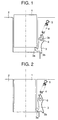
claim 1. - Fig. 1 is a cross-sectional view showing a state of a film cartridge on the way to loading into a film cartridge loading portion of a camera according to a first embodiment of the present invention.
- Fig. 2 is a cross-sectional view showing a state of loading completion of an usable or unexposed film cartridge as well.
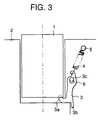
- Fig. 3 is a cross-sectional view showing a state of loading prevention of an unusable or exposed film cartridge as well.
- Fig. 4 is a enlarged cross-sectional view showing loading of the usable film cartridge as well.
- Fig. 5 is a enlarged cross-sectional view showing loading of the unusable film cartridge as well.
- Fig. 6 is a plane view of the usable film cartridge used in the first embodiment of the present invention as it is seen from the bottom side thereof.
- Fig. 7 is a plane view of the unusable film cartridge used as well.
- Fig. 8 is a cross-sectional view showing a structure of a film cartridge loading portion of a camera according to a second embodiment of the present invention.
- Referring to drawings, preferred embodiments according to the present invention will be described hereinbelow.
- A
film cartridge 1 used in the embodiments, as shown in Figs. 4 and 5, includes adisk 7 having a notch part on the periphery thereof, and thedisk 7 is attached to an unillustrated rotation shaft of thefilm cartridge 1. Thedisk 7 changes a stop position of the rotation thereof, thereby forming either a groove on the bottom side of thefilm cartridge 1 or a cover thereon. - Figs. 1 to 7 show a structure of a film cartridge loading portion according to a first embodiment of the present invention. Referring to Fig. 1, there are provided a
film cartridge 1 which completely stores a film therein and thrusts out the film therefrom, acartridge chamber 2 of a camera body, a lock-out lever or so called determination means 3 for preventing cartridge loading with respect to an exposed or unusable film cartridge, aprojection 3a which is put in agroove 9, as shown in Fig. 5, in case of the exposed or unusable film cartridge, a rotating connection-lock part 3b of the lock-outlever 3, anoval hole 3c, aspring 4 for biasing lock-outlever 3 in the one side direction (the upper side from diagonal right-hand), aspring shaft 5 fixed on the body, alever shaft 6 fixed on the body as rotation axis of the lock-outlever 3, and in Fig. 4, thedisk 7 for forming the presence of thelock groove 9, changing the stop position in response to whether the loaded film is unused or exposed. - As shown in Fig. 4, when an usable film cartridge is loaded, the
disk 7 is positioned not to form thelock groove 9. As shown in Fig. 5, when an unusable film cartridge is loaded, thedisk 7 is positioned to form thelock groove 9. Fig. 6 is a plane view of the usable film cartridge as shown in Fig. 4 as it is seen from the bottom side thereof and Fig. 7 is a plane view of the unusable film cartridge as shown in Fig. 5 as well. - Figs. 6 and 7 show whether or not the
disk 7 is positioned on thelock groove 9. The position of the disk determines whether or not theprojection 3a of the lock-outlever 3 is put in thegroove 9. - Next, an actual operation with respect to such a lock-out mechanism will be described. Referring to Fig. 1, when the
film cartridge 1 is on the way to loading, that is, when the lock-outlever 3 is in a normal state, the lock-outlever 3 receives clockwise mechanical power from thespring 4. On this state, therefore, the rotating connection-lock part 3b is pressed against the camera body to restrict the rotation. - Next, referring to Fig. 2, when the loaded cartridge is usable, the
projection 3a of the lock-outlever 3 contacts with thedisk 7 of thefilm cartridge 1 as shown in Fig. 4 and the lock-outlever 3 rotates counterclockwise around thelever shaft 6. As a result, thefilm cartridge 1 makes the lock-out lever 3 rotate counterclockwise, whereby thefilm cartridge 1 is completely loaded in a desired position of thecartridge chamber 2. - As shown in Fig. 3, when the loaded
cartridge 1 is unusable, theprojection 3a of the lock-outlever 3 is put in thegroove 9 formed by the difference in the stop position of thedisk 7 and the rotation of the lock-outlever 3 is restricted. Also, when the loaded cartridge is more deeply pressed, the lock-outlever 3 moves downwardly along theoval hole 3c to strike the bottom side of the cartridge chamber of the camera body (structure member of the camera), thereby preventing the further approach of the unusable cartridge into thecartridge chamber 2, and informing a user that the cartridge being loaded is unusable. That is, the lock-out lever 3 strikes the bottom side of the cartridge chamber of the camera body by the excessive power generated by the loading operation and prevents to move further downwardly, whereby a load given from theoval hole 3c of the lock-outlever 3 to thelever shaft 6 can reduce. - Fig. 4 is an enlarged diagram adjacent to the lock-out
lever 3 at the time when the usable film cartridge is loaded. Referring to Fig. 4, thedisk 7 of thefilm cartridge 1 covers the groove therewith to prevent to put theprojection 3a of the lock-outlever 3 in the groove. Therefore, by the loaded usable film cartridge, the lock-out lever 3 resists thespring 4 to rotate counterclockwise around thelever shaft 6. - Fig. 5 is an enlarged diagram adjacent to the lock-out
lever 3 when the unusable film cartridge is loaded. Referring to Fig. 5, anotch part 9 provided on thedisk 7 of thefilm cartridge 1 forms the groove to put theprojection 3a of the lock-outlever 3 therein. - Fig. 8 is a diagram showing a structure of a film cartridge loading portion of a camera according to a second embodiment of the present invention. In Fig. 8, elements of which are identical to those shown in the first embodiment adopt the same numerals to omit a description thereof. In the drawing, there are provided a connection-
lock part 3d for preventing downward movement of the lock-outlever 3 and aprojection 8 of the camera body. - In the above each of embodiments, as a method for inhibiting the loading of the unusable cartridge, the invention is not limited to the shape of the lock-out
lever 3. The present invention can be applied, also to another shape of lock-out lever, for example a slide cam. - Further, in case the unusable cartridge is loaded, as a member with which the lock-out lever 3 contacts and a movement of which is inhibited, a member except the structure member of the camera of the above embodiments can be included in the present invention.
- In this embodiment, the different point from the first embodiment is that, when the unusable film cartridge is loaded, the
projection 3a of the lock-outlever 3 is put in the groove to move lock-outlever 3 downwardly along theoval hole 3c, and on this moment, the connection-lock part 3d strikes theprojection 8 of the body to prevent downward movement of the lock-outlever 3. Also, the other things are the same as those shown in the first embodiment. - Furthermore, according to the present invention, there can be applied various types of cartridge except the cartridge shown in the embodiments, cartridges including image recording mediums but film and also, the other cartridges and loading materials except cartridge.
- Furthermore, according to the present invention, there can be applied a single-lens reflex camera, a lens-shutter camera, a video camera and also, a optical apparatus except camera and other apparatus.
- Furthermore, according to the present invention, it is to be understood that the loading direction of the cartridge is not limited to the direction of the above-mentioned embodiments.
- While the present invention has been described with respect to what is presently considered to be the preferred embodiments, it is to be understood that the invention is not limited to the disclosed embodiments. To the contrary, the invention is intended to cover various modifications and equivalent arrangement included within the scope of the appended claims.
Claims (6)
- A film cartridge loading apparatus for loading film cartridges having a mechanical indicator means indicating whether the film is exposed or unexposed comprising:the apparatus being characterized in that,determination means (3) including means (3a) which upon loading the cartridge engage with the cartridge indicator means for determining whether the cartridge (1) is exposed;supporting means (6) for supporting said determination means (3) and enabling movement of the latter;the determination means (3) includes means (3c) which upon the loading of the cartridge allows the determination means to vary its state in accordance with whether the cartridge (1) is exposed so as to move together with the cartridge, and in that the apparatus (2, 8) and the determination means (3c, 3b, 3d) are adapted to inhibit the loading of the exposed cartridge (1) by preventing the further movement of said determination means (3) while preventing said determination means (3) from exerting a force on said supporting means (6).
- An apparatus according to claim 1, wherein said supporting means (6) includes means for rotatably supporting said determination means (3).
- An apparatus according to claim 1, wherein said suppcrting means (6) includes means (3c) for slidably supporting said determination means (3).
- An apparatus according to claim 1, 2 and 3 further comprising means (4) for urging said supporting means (6) in a predetermined direction.
- An apparatus according to claim 1, wherein said prevention means includes a structure member of a camera.
- A camera comprising a cartridge loading apparatus according to any one of the preceding claims 1 to 5.
Applications Claiming Priority (3)
| Application Number | Priority Date | Filing Date | Title |
|---|---|---|---|
| JP111126/93 | 1993-04-15 | ||
| JP11112693 | 1993-04-15 | ||
| JP5111126A JPH06301106A (en) | 1993-04-15 | 1993-04-15 | Camera |
Publications (3)
| Publication Number | Publication Date |
|---|---|
| EP0620477A2 EP0620477A2 (en) | 1994-10-19 |
| EP0620477A3 EP0620477A3 (en) | 1995-03-29 |
| EP0620477B1 true EP0620477B1 (en) | 1999-11-24 |
Family
ID=14553106
Family Applications (1)
| Application Number | Title | Priority Date | Filing Date |
|---|---|---|---|
| EP94105794A Expired - Lifetime EP0620477B1 (en) | 1993-04-15 | 1994-04-14 | Cartridge loading apparatus and camera |
Country Status (7)
| Country | Link |
|---|---|
| US (1) | US6052543A (en) |
| EP (1) | EP0620477B1 (en) |
| JP (1) | JPH06301106A (en) |
| KR (1) | KR100217431B1 (en) |
| CN (1) | CN1066264C (en) |
| DE (1) | DE69421741T2 (en) |
| TW (1) | TW250545B (en) |
Families Citing this family (2)
| Publication number | Priority date | Publication date | Assignee | Title |
|---|---|---|---|---|
| JPH095861A (en) * | 1995-06-15 | 1997-01-10 | Olympus Optical Co Ltd | Camera |
| JP3035011U (en) * | 1996-08-23 | 1997-03-11 | 利男 野口 | Film number control device |
Family Cites Families (10)
| Publication number | Priority date | Publication date | Assignee | Title |
|---|---|---|---|---|
| US4998123A (en) * | 1989-11-14 | 1991-03-05 | Eastman Kodak Company | Film cassette with exposure status indicator |
| EP0467644B1 (en) * | 1990-07-16 | 1996-12-18 | Nikon Corporation | Film magazine and camera for loading the same |
| US5079579A (en) * | 1990-10-11 | 1992-01-07 | Eastman Kodak Company | Camera apparatus for use with film cassette having locking means for exposure status indicator |
| US5032861A (en) * | 1990-10-15 | 1991-07-16 | Eastman Kodak Company | Film cassette with lock-out means for preventing load of exposed film |
| JPH04204839A (en) * | 1990-11-30 | 1992-07-27 | Minolta Camera Co Ltd | Camera system |
| US5307099A (en) * | 1990-11-30 | 1994-04-26 | Minolta Camera Kabushiki Kaisha | Film cartridge accomodating device which prevents previously used cartridges from being employed in a camera or the like |
| US5122820A (en) * | 1991-04-03 | 1992-06-16 | Eastman Kodak Company | Camera apparatus and method for detecting film speed indication |
| US5274412A (en) * | 1992-07-06 | 1993-12-28 | Eastman Kodak Company | Film cassette with frangible spool lock and cam |
| US5280327A (en) * | 1992-07-06 | 1994-01-18 | Eastman Kodak Company | Cassette re-load prevention apparatus |
| US5347334A (en) * | 1993-11-30 | 1994-09-13 | Eastman Kodak Company | Film cassette with bar-coded film spool and provision for film double exposure prevention |
-
1993
- 1993-04-15 JP JP5111126A patent/JPH06301106A/en active Pending
-
1994
- 1994-04-14 KR KR1019940007783A patent/KR100217431B1/en not_active IP Right Cessation
- 1994-04-14 TW TW083103318A patent/TW250545B/zh active
- 1994-04-14 DE DE69421741T patent/DE69421741T2/en not_active Expired - Fee Related
- 1994-04-14 EP EP94105794A patent/EP0620477B1/en not_active Expired - Lifetime
- 1994-04-15 CN CN94103592.1A patent/CN1066264C/en not_active Expired - Fee Related
-
1997
- 1997-09-02 US US08/921,543 patent/US6052543A/en not_active Expired - Fee Related
Also Published As
| Publication number | Publication date |
|---|---|
| KR100217431B1 (en) | 1999-09-01 |
| DE69421741D1 (en) | 1999-12-30 |
| EP0620477A3 (en) | 1995-03-29 |
| TW250545B (en) | 1995-07-01 |
| CN1066264C (en) | 2001-05-23 |
| EP0620477A2 (en) | 1994-10-19 |
| JPH06301106A (en) | 1994-10-28 |
| CN1113012A (en) | 1995-12-06 |
| DE69421741T2 (en) | 2000-06-29 |
| US6052543A (en) | 2000-04-18 |
Similar Documents
| Publication | Publication Date | Title |
|---|---|---|
| US5307099A (en) | Film cartridge accomodating device which prevents previously used cartridges from being employed in a camera or the like | |
| US5600393A (en) | Mechanism for opening and closing cartridge compartment cover of camera | |
| EP0620477B1 (en) | Cartridge loading apparatus and camera | |
| JP2824662B2 (en) | Method of manufacturing film-integrated camera and film-integrated camera | |
| JPH08234283A (en) | Camera with interlock mechanism for prevention of tilt of film loading chamber | |
| JP3018415B2 (en) | camera | |
| US5432575A (en) | Mechanism for locking cartridge compartment cover of camera | |
| US5799221A (en) | Camera | |
| JPH07209736A (en) | Cartridge takeout device for camera | |
| US6400911B1 (en) | Camera with a shutter release device | |
| EP0467644B1 (en) | Film magazine and camera for loading the same | |
| US6179494B1 (en) | Camera | |
| EP0441662B1 (en) | Film magazine and camera | |
| US3852784A (en) | Early metering failure prevention device | |
| JPH09281587A (en) | Film loading device | |
| JP2811644B2 (en) | Camera and cartridge loading device | |
| JP3414555B2 (en) | Camera film cartridge loading device | |
| US6360061B1 (en) | Camera with a device for locking the film feed | |
| US6463219B1 (en) | Camera with a film perforation wheel | |
| US6108498A (en) | Cartridge receiving apparatus | |
| JP3498558B2 (en) | Paper feeder | |
| JP3438470B2 (en) | camera | |
| JP3420828B2 (en) | camera | |
| JPH04204839A (en) | Camera system | |
| JPH07319058A (en) | Camera using film cartridge with movable shading door |
Legal Events
| Date | Code | Title | Description |
|---|---|---|---|
| PUAI | Public reference made under article 153(3) epc to a published international application that has entered the european phase |
Free format text: ORIGINAL CODE: 0009012 |
|
| AK | Designated contracting states |
Kind code of ref document: A2 Designated state(s): DE FR GB |
|
| PUAL | Search report despatched |
Free format text: ORIGINAL CODE: 0009013 |
|
| AK | Designated contracting states |
Kind code of ref document: A3 Designated state(s): DE FR GB |
|
| 17P | Request for examination filed |
Effective date: 19950816 |
|
| 17Q | First examination report despatched |
Effective date: 19970627 |
|
| GRAG | Despatch of communication of intention to grant |
Free format text: ORIGINAL CODE: EPIDOS AGRA |
|
| GRAG | Despatch of communication of intention to grant |
Free format text: ORIGINAL CODE: EPIDOS AGRA |
|
| GRAH | Despatch of communication of intention to grant a patent |
Free format text: ORIGINAL CODE: EPIDOS IGRA |
|
| GRAH | Despatch of communication of intention to grant a patent |
Free format text: ORIGINAL CODE: EPIDOS IGRA |
|
| GRAA | (expected) grant |
Free format text: ORIGINAL CODE: 0009210 |
|
| AK | Designated contracting states |
Kind code of ref document: B1 Designated state(s): DE FR GB |
|
| PG25 | Lapsed in a contracting state [announced via postgrant information from national office to epo] |
Ref country code: FR Free format text: LAPSE BECAUSE OF FAILURE TO SUBMIT A TRANSLATION OF THE DESCRIPTION OR TO PAY THE FEE WITHIN THE PRESCRIBED TIME-LIMIT Effective date: 19991124 |
|
| REF | Corresponds to: |
Ref document number: 69421741 Country of ref document: DE Date of ref document: 19991230 |
|
| PG25 | Lapsed in a contracting state [announced via postgrant information from national office to epo] |
Ref country code: GB Free format text: LAPSE BECAUSE OF NON-PAYMENT OF DUE FEES Effective date: 20000414 |
|
| EN | Fr: translation not filed | ||
| PLBE | No opposition filed within time limit |
Free format text: ORIGINAL CODE: 0009261 |
|
| STAA | Information on the status of an ep patent application or granted ep patent |
Free format text: STATUS: NO OPPOSITION FILED WITHIN TIME LIMIT |
|
| 26N | No opposition filed | ||
| GBPC | Gb: european patent ceased through non-payment of renewal fee |
Effective date: 20000414 |
|
| PGFP | Annual fee paid to national office [announced via postgrant information from national office to epo] |
Ref country code: DE Payment date: 20070412 Year of fee payment: 14 |
|
| PG25 | Lapsed in a contracting state [announced via postgrant information from national office to epo] |
Ref country code: DE Free format text: LAPSE BECAUSE OF NON-PAYMENT OF DUE FEES Effective date: 20081101 |