EP0620193B1 - Ein Kübel-Weitergabemechanismus - Google Patents
Ein Kübel-Weitergabemechanismus Download PDFInfo
- Publication number
- EP0620193B1 EP0620193B1 EP94302577A EP94302577A EP0620193B1 EP 0620193 B1 EP0620193 B1 EP 0620193B1 EP 94302577 A EP94302577 A EP 94302577A EP 94302577 A EP94302577 A EP 94302577A EP 0620193 B1 EP0620193 B1 EP 0620193B1
- Authority
- EP
- European Patent Office
- Prior art keywords
- parison
- neck
- ring
- section
- moulds
- Prior art date
- Legal status (The legal status is an assumption and is not a legal conclusion. Google has not performed a legal analysis and makes no representation as to the accuracy of the status listed.)
- Expired - Lifetime
Links
- 230000007246 mechanism Effects 0.000 title claims description 79
- 239000011521 glass Substances 0.000 claims description 25
- 230000000712 assembly Effects 0.000 claims description 10
- 238000000429 assembly Methods 0.000 claims description 10
- 239000006063 cullet Substances 0.000 claims description 5
- 238000010276 construction Methods 0.000 claims 1
- 238000001816 cooling Methods 0.000 description 3
- 238000000034 method Methods 0.000 description 3
- 230000008569 process Effects 0.000 description 2
- 230000009467 reduction Effects 0.000 description 2
- 230000009471 action Effects 0.000 description 1
- 239000011324 bead Substances 0.000 description 1
- 230000015572 biosynthetic process Effects 0.000 description 1
- 238000007664 blowing Methods 0.000 description 1
- 230000007547 defect Effects 0.000 description 1
Images

Classifications
-
- C—CHEMISTRY; METALLURGY
- C03—GLASS; MINERAL OR SLAG WOOL
- C03B—MANUFACTURE, SHAPING, OR SUPPLEMENTARY PROCESSES
- C03B9/00—Blowing glass; Production of hollow glass articles
- C03B9/13—Blowing glass; Production of hollow glass articles in gob feeder machines
- C03B9/14—Blowing glass; Production of hollow glass articles in gob feeder machines in "blow" machines or in "blow-and-blow" machines
- C03B9/16—Blowing glass; Production of hollow glass articles in gob feeder machines in "blow" machines or in "blow-and-blow" machines in machines with turn-over moulds
- C03B9/165—Details of such machines, e.g. guide funnels, turn-over mechanisms
Definitions
- This invention is concerned with a transfer mechanism for transferring and inverting parisons in a section of a glassware forming machine from a blank station where the parisons are formed in a parison mould to a second forming station where the parison is blown to form a container in a blow mould.
- a conventional I.S. glass container forming machine comprises a series of sections arranged along side each other and operating out of phase with each other. Each section is equipped with a single parison transfer mechanism carrying one or more neck-rings. Taking single gob operation as an example, the machine cycle commences with the neck-ring in a reverted position and the parison mould closed around it. A charge of glass enters the upper end of the parison mould and is blown or pressed into a parison shape with some glass being forced into the space between the neck-ring and a plunger to form a finish end of the final container. The parison mould then opens leaving the parison held by its finish end in the neck-ring.
- the invert mechanism then operates to carry the parison from the parison forming station and to invert it into the blow mould station where the blow mould closes around it.
- the neck-ring is then opened, dropping the parison into the blow mould where it is supported by a bead formed on the finish.
- the invert mechanism returns the neck-ring to the parison forming station and the parison mould closes around it ready for the next charge of glass. Meanwhile the parison hanging in the blow mould is blown into the final container.
- the glass in the finish is not cool enough, and thus not hard enough to maintain its shape accurately when the parison is transferred to the blow mould, leading to subsequent distortion and loss of ware. Further reduction in the weight of the finish is limited because, should the distance between the neck-ring and the plunger inside it become too small it is not possible to force glass into the neck-ring and containers are formed with incomplete finishes.
- One method available to reduce this problem is to apply more cooling to the neck-ring. This is only partially effective because, if the neck-ring becomes too cold, defects are formed in the container finish. Also because of the very low thermal conductivity of the glass a cooler neck-ring does not take out appreciably more heat from the glass. A more effective solution to the problem would be to increase the time of contact between the finish of the container and the neck-ring but this is not possible with a single neck-ring per blank mould without slowing down the machine cycle which is commercially unacceptable.
- the parison would be made and inverted in the normal way but instead of being dropped into the blow mould when the neck-rings open, the neck-rings would remain closed during at least part of the blowing operation.
- the extra time available for contact between the glass finish and the neck-rings would extend to almost a complete machine cycle if required. More time would also be available for forming the parison, for next cycle would not have to wait for the neck-rings to invert, open and return. Instead, an empty set of neck-rings would be available to move into position as soon as the filled neck-rings had left. Additionally, the speed of invert could be beneficially reduced, for the inverting set of neck-rings would not be required to be back in the reverted position as quickly as possible ready for the next cycle.
- US-A-34 34 820 describes a machine in which a chain carrying a series of neck-rings travels in a vertical loop thus holding returning neck-rings clear of ones carrying glass. Such an arrangement is only usable in a machine in which the parison is formed in an upright rather than an inverted position.
- US-A-4058388 describes a machine with two neck-rings mounted on racks in which interference is avoided by sliding the two mechanisms horizontally parallel to the centre line of the section. Such an arrangement is mechanically complex and essentially requires a considerable width of the section.
- the present invention provides in one of its aspects a parison transfer mechanism for use in an individual section glassware forming machine comprising
- parison transfer mechanism provides the possibility of various arrangements of the forming mechanism in a section of an I.S. machine.
- the present invention also provides in another of its aspects a section of an individual section glassware forming machine comprising
- the present invention also provides in another of its aspects a section of an individual section glassware forming machine comprising
- the present invention also provides in another of its aspects a section of an individual section glassware forming machine comprising
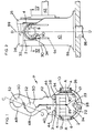
- a parison transfer mechanism P is shown in Figure 1 and is intended for use in an individual section glassware forming machine.
- Such machines comprise a parison mould assembly comprising one or more parison moulds in which a gob of glass may be formed into a parison and a blow mould assembly (or sometimes two blow mould assemblies) comprising a corresponding number of blow moulds in which a parison may be blown into a container, and means for transferring parisons from the parison moulds to the blow moulds.
- Such means usually transfers the parisons directly to the blow moulds, but sometimes the parisons are transferred to an intermediate, reheat, station from which they are then transferred to the blow moulds.
- the parison transfer mechanism P comprises a supporting member in the form of a block 2 comprising opposed circular trunnions 4,6 which are supported in bearings 8 in brackets 10,12 so that the block 2 can be rotated about a horizontal invert axis 14 (shown by A-A in Figures 1 and 4.) between invert and revert positions.
- the block 2 supports a shaft 22 whose axis 23 (shown as B-B in Figure 3) is perpendicular to the face 18 and is thus vertical when the block 2 is in its revert position
- the transfer mechanism P comprises two neck-ring supporting members 24, 26 which are mounted on the shaft 22 for angular movement about the axis 23.
- the member 24 comprises lugs 28 and 30, and the member 26 lugs 32 and 34 by which they are supported on the shaft 22, the lugs 30 and 32 being located against the plane faces 18 and 19 of the block 2 and the lugs 28 and 34 lying respectively against and outside the lugs 32 and 30.
- the supporting members 24,26 each comprise a tongued locating member 36,38 respectively.
- Neck-ring arms 40,42 having locating T slots 44,46 respectively are positioned on the members 36,38 and clamped in position at the desired height.
- the neck-ring arm 40 comprises two semicircular neck-ring supports 48,48 and the neck-ring arm 42 two similar neck-ring supports 50,50.
- the neck-ring arms When the neck-ring arms are in a closed condition, as shown in Figure 1 two neck-ring supporting apertures 52,52 are provided. It will be understood that, according to the configuration of the machine in which the transfer mechanism is to be used, the neck-ring arms may comprise one or a plurality of neck-ring supports.
- axes of the neck-ring apertures lie in a plane [C-C in Figure 1] and as can be seen this plane is inclined at an angle, specifically in the illustrated mechanism 67.5°, to the axis A-A about which the neck-ring arms 40,42 rotate.
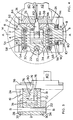
- the mechanism comprises means for moving the neck-ring arms 40,42 towards and away from each other between open and closed conditions.
- the block 2 comprises two bores 54,56 and strong tension springs 58,60 extend respectively between a pin 62 in the bore 54 and a pin 64 secured between the lugs 28 and 30 and between a pin 66 in the bore 56 and a pin 68 secured between the lugs 32 and 34.
- these springs 58,60 act to urge the neck-ring arms 40-42 into their closed condition.
- a piston 72 comprising a head 74 and a piston rod 76.
- the bore 70 is closed by a bushing 78 having a central bore 79 through which the rod 76 passes.
- the rod 76 comprises a tapered end portion 80 which engages cam faces 82,84 on the supporting member 24,26.
- Air under pressure is supplied to the bore 70 on both sides of the piston head 74 through bores (not shown) in the block 2.
- the brackets 10 and 12 are integral with a base 86 which rests against a top plate 16 of the machine and is attached to a vertical shaft 88 which is rotatably mounted in the machine about a vertical axis 89 (shown as D-D in Figure 2).
- a chain wheel 90 Secured to the trunnion 4 between the bracket 10 and the block 2 is a chain wheel 90 which is driven by a chain 94.
- Movement of the chain 94 thus rotates the neck-ring arms 40 and 42 about the axis A-A. between revert and invert positions
- the parison transfer mechanism P can be incorporated in a section of a glassware forming machine in several different arrangements.
- a first arrangement is shown diagrammatically in plan in Figure 5.
- This shows a section of an individual section glassware forming machine comprising a double gob parison mould assembly 92 comprising two parison moulds 96 (for clarity two half parison moulds are shown in their open positions) and a blow mould assembly 98 correspondingly comprising two blow moulds 100 (again two half blow moulds are shown in their open position) in which a formed parison may be blown into a container.
- the blow moulds 100 and the parison moulds 96 are, when in their closed position, aligned along a centre axis E-E of the section.
- the mechanism P A starts in a first position as shown, its neck-ring arms in a first, parison engaging position with the neck-ring supporting apertures 52A 52A in their revert position aligned with and below parison moulds 96 which are in their closed position.
- Gobs of glass are then supplied to the parison moulds 96 and formed into parisons in a conventional manner by use of a baffle and plunger mechanism (not shown).
- the parison moulds 96 are then opened, leaving the parisons supported by their neck portions in the neck-ring supports 50A 50A of the transfer mechanism P A .
- the horizontal axis A-A of the mechanism P A is, at this stage, inclined to the centre axis of the section at an angle of about 671 ⁇ 2°.
- the mechanism P A then moves to a second position by a combination of two movements - firstly a rotation of the neck-ring arms 40 A 42 A through approximately 180° about the horizontal axis A-A from their revert to their invert position and secondly a simultaneous clockwise rotation of the mechanism through about 45° about its vertical axis 89A.
- the neck-ring arms are kept in their movement within the boundaries of the section (indicated by boundary lines in Figure 5).
- a second arrangement of a section is shown in Figure 6. This is in general similar to the first arrangement comprising two transverse mechanisms Pc and P D , save that the blow mould assembly comprises parallel opening moulds rather than arcuately opening moulds as is provided in the first arrangement.
- a parallel mould assembly occupies slightly less space than an arcuate assembly: the second arrangement is provided with two cullet chutes 102, 104, each extending partway into the adjoining sections.
- the second arrangement operates in just the same way as the first arrangement, but if it is required to reject a parison held in the transfer mechanism Pc, the mechanism may be caused to rotate the neck-ring arms 40c, 42c about the horizontal axis A-A, without causing simultaneous rotation about the vertical axis 89c. This brings the parisons held in the neck-ring apertures over the cullet chute 102 into which, on opening the neck-ring arms 40c, 42c, the parisons may be dropped.
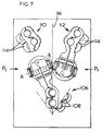
- Figure 7 shows a third arrangement of a section of a double gob glassware forming machine.
- This section comprises a parison mould assembly 106 (one half of which is shown in an open position) comprising two parison moulds 108 in which a gob of glass may be formed into a parison, two blow mould assemblies 110,112 each correspondingly comprising two blow moulds 114 in which a formed parison may be blown into a container, the blow mould assemblies 110,112 being symmetrically positioned transversely apart across a centre line 116 of the section.
- the third arrangement comprises two parison transfer mechanisms P E and P F , P E transferring parisons to the blow mould assembly 110, P F to the assembly 112.
- the parison transfer mechanisms P E and P F are mounted spaced transversely apart across the axis of the section, and are constituted as the transfer mechanism P save that they are not mounted for rotation about a vertical axis. As can be seen the horizontal axes of rotation of the neck-ring arms of the two mechanisms P E and P F are inclined to the centre axis of the section.
- parison transfer mechanisms operate alternately, by movement of their neck-ring arms 180° about their horizontal axes, to transfer formed parisons to the blow moulds, the mechanism P E transferring to the mould assembly 110 and the mechanism P F to the mould assembly 112.
Landscapes
- Engineering & Computer Science (AREA)
- Chemical & Material Sciences (AREA)
- Manufacturing & Machinery (AREA)
- Materials Engineering (AREA)
- Organic Chemistry (AREA)
- Containers Having Bodies Formed In One Piece (AREA)
- Blow-Moulding Or Thermoforming Of Plastics Or The Like (AREA)
- Re-Forming, After-Treatment, Cutting And Transporting Of Glass Products (AREA)
Claims (8)
- Ein Külbel-Übergabemechanismus (P) zur Verwendung in einer Einzelabschnitts-Glaswarenformgebungsmaschine, aufweisend:ein Halteglied (2), das zum Drehen um eine horizontale Achse (A-A) angebracht ist,zwei Halsringarme (40, 42), die in dem Halteglied (2) gehaltert sind, Mittel zum Bewegen der Halsringarme (40, 42) aufeinander zu und voneinander fort zwischen offenen und geschlossenen Zuständen,
wobei jeder Halsringarm (40, 42) eine Anzahl von Halsringhaltern (48, 50) aufweist, derart, daß, wenn sich die Arme (40, 42) in ihrem geschlossenen Zustand befinden, eine Anzahl von Halsringhalteöffnungen (52) geschaffen werden, wobei die Achsen der Öffnungen in einer Ebene ausgerichtet sind,
wobei die Ebene gegen die Achse (A-A) geneigt ist, um die sich die Halsringarme (40, 42) und das Halteglied (2) drehen. - Ein Abschnitt einer Einzelabschnitts-Glaswarenformgebungsmaschine, aufweisend:Eine Külbelformeinheit (106), die eine oder mehrere Külbelformen umfaßt, in welcher ein Tropfen aus Glas in einen Külbel geformt werden kann,zwei Fertigformeinheiten (110, 112), wobei jede eine entsprechende Anzahl von Fertigformen aufweist, in welchen ein geformter Külbel zu einem Behälter aufgeblasen werden kann, wobei die Fertigformeinheiten transversal voneinander jenseits einer Mittelachse (116) des Maschinenabschnittes beabstandet sind,Mittel zum Übergeben von Külbeln aus den Külbelformen an die Fertigformen, aufweisend: Zwei Külbel-Übergabemechanismen (PE, PF), von denen der eine einen Külbel an eine der Fertigformeinheiten übergibt und den anderen Külbel an die andere Einheit übergibt, wobei die Külbel-Übergabemechanismen transversal voneinander beabstandet und jenseits der Mittellinie (116) des Maschinenabschnittes angebracht sind, und
wobei jeder Külbel-Übergabemechanismus ein Halteglied (2) aufweist, das zum Drehen um eine horizontale Achse (A-A) angebracht ist, wobei zwei Halsringarme (40, 42) in dem Halteglied zum Drehen um die horizontale Achse zwischen einer ersten, den Külbel erfassenden Position, und einer zweiten, den Külbel freigebenden Position angebracht sind, undMittel zum Bewegen der Halsringarme (40, 42) aufeinander zu und voneinander fort zwischen einem offenen Zustand und einem geschlossenem Zustand, wobei jeder Arm einen oder mehrere Halsringhalter (48, 50) aufweist, derart, daß wenn sich die Halsringarme (40, 42) in ihrem geschlossenem Zustand befinden, eine Anzahl von Halsringhalteöffnungen (52) dargeboten werden, die der Anzahl der Külbelformen entsprechen, wobei die horizontalen Drehachsen (A-A) der beiden Halsringarme der beiden Külbel-Übergabemechanismen gegen die Mittelachse (116) des Maschinenabschnittes geneigt sind. - Maschinenabschnitt nach Anspruch 2, dadurch gekennzeichnet, daß die beiden Külbel-Übergabemechanismen (PE, PF) einen identischen Aufbau besitzen und symmetrisch entlang der Mittelachse (116) des Abschnittes positioniert sind, wobei die beiden horizontalen Drehachsen (A-A) symmetrisch gegen die Mittelachse des Maschinenabschnittes geneigt sind.
- Maschinenabschnitt nach Anspruch 3, dadurch gekennzeichnet, daß die Külbelformeinheit (106) eine Anzahl von Külbelformen aufweist, und jeder Külbel-Übergabemechanismus (PE, PF) eine entsprechende Anzahl von Halsringhaltern (58, 50) aufweist, die dieselbe Anzahl von Halsringhaltöffnungen (52) darbieten, welche mit ihren Achsen in einer Ebene ausgerichtet sind, die gegen die Achse (A-A), um welche die Halsringarme (40, 42) drehen, geneigt sind.
- Ein Abschnitt einer Einzelabschnitts-Glaswarenformgebungsmaschine, die aufweist:eine Külbelformeinheit (92), die eine Külbelform (96) aufweist, in der ein Tropfen aus Glas in einen Külbel geformt werden kann,eine Fertigformeinheit (98), die eine Fertigform aufweist, in der ein geformter Külbel zu einem Behälter aufgeblasen werden kann, wobei die Fertigform und die Külbelform entlang einer Mittelachse (E-E) des Maschinenabschnittes ausgerichtet sind, wenn sie sich in geschlossenem Zustand befinden,Mittel zum Übergeben von Külbeln aus der Külbelform an die Fertigform, welche zwei Külbel-Übergabemechanismen (PA, PB) umfassen, von denen jeder ein Halteglied (2) aufweist, das zum Drehen um eine horizontale Achse (A-A) angebracht ist,zwei Halsringarme (40, 42), die an dem Halteglied angebracht sind,Mittel zum Bewegen der Halsringarme (40, 42) aufeinander zu und voneinander fort zwischen einem offenen und einem geschlossenen Zustand,
wobei jeder Arm einen Halsringhalter (48, 50) aufweist, derart, daß, wenn sich die Halsringarme in ihrer geschlossenen Position befinden, eine Halsring-Halterungsöffnung (52) geschaffen wird,
wobei die beiden Übergabemechanismen (PA, PB) an einander gegenüberliegenden Seiten der Mittelachse (E-E) des Maschinenabschnittes angeordnet sind, wobei jeder Mechanismus zum Drehen um eine vertikale Achse (89A) angeordnet ist,
wobei jeder Übergabemechanismus seinerseits wirksam wird, um seine Halsringarme aus einer ersten Position, in der die Halsring-Halterungsöffnung mit der Külbelform ausgerichtet ist und die horizontale Achse gegenüber der Mittelachse geneigt ist, in eine zweite Position zu bewegen, in der die Halsring-Halterungsöffnung durch eine Bewegung der Halsringarme von etwa 180° um die horizontale Achse mit der Fertigform ausgerichtet wird, während sich der Übergabemechanismus um eine vertikale Achse dreht. - Ein Abschnitt einer Individualabschnitts-Glaswarenformgebungsmaschine, aufweisend:eine Külbelformeinheit (92), die eine Anzahl von Külbelformen (96) aufweist, in denen ein Tropfen aus Glas in einen Külbel geformt werden kann,eine Fertigformeinheit (98), die eine entsprechende Anzahl von Fertigformen aufweist, in denen die geformten Külbel zu Behältern aufgeblasen werden können, wobei die Fertigformen und die Külbelformen entlang einer Mittelachse (E-E) des Maschinenabschnittes ausgerichtet sind,
und Mittel zum Übergeben der Külbel aus den Külbelformen an die Fertigformen, welche zwei Külbel-Übergabemechanismen (PA,PB) gemäß Anspruch 1 aufweisen, wobei die Mechanismen an einander gegenüberliegenden Seiten der Mittelachse angeordnet sind und jeweils zum Drehen um eine vertikale Achse (89) so angebracht sind, daß jeder Übergabemechanismus seinerseits betätigt wird, um seine Halsringarme durch Bewegen der Halsringarme um etwa 180° um die horizontale Achse (A-A) von einer ersten Position, in der die Haltering-Halterungsöffnungen (52) mit den Külbelformen ausgerichtet sind, in eine zweite Position zu bewegen, in der die Öffnungen mit den Fertigformen ausgerichtet sind, während sich der Übergabemechanismus um seine vertikale Achse dreht. - Maschinenabschnitt nach einem der Ansprüche 5 und 6, wobei der Abschnitt eine der Fertigformeinheit (98) benachbarte Glasbruchrutsche (102, 104) aufweist, die so positioniert ist, daß, falls der Külbel-Übergabemechanismus (PA, PB) veranlaßt wird, ohne Drehung um seine vertikale Achse (89) zu arbeiten, der Mechanismus einen Külbel von der Külbelformeinheit (92) in eine Position über der Glasbruchrutsche trägt, so daß ein auszusondernder Külbel in die Glasbruchrutsche fallen gelassen werden kann.
- Maschinenabschnitt nach einem der Ansprüche 2 bis 7, bei dem die Halsringarme (40, 42) jedes Külbel-Übergabemechanismus' (P) für eine geschwenkte Bewegung zwischen ihren offenen und geschlossenen Zuständen montiert sind.
Applications Claiming Priority (2)
| Application Number | Priority Date | Filing Date | Title |
|---|---|---|---|
| GB939307532A GB9307532D0 (en) | 1993-04-13 | 1993-04-13 | A parison transfer mechanism |
| GB9307532 | 1993-04-13 |
Publications (3)
| Publication Number | Publication Date |
|---|---|
| EP0620193A2 EP0620193A2 (de) | 1994-10-19 |
| EP0620193A3 EP0620193A3 (de) | 1995-04-12 |
| EP0620193B1 true EP0620193B1 (de) | 1998-07-08 |
Family
ID=10733688
Family Applications (1)
| Application Number | Title | Priority Date | Filing Date |
|---|---|---|---|
| EP94302577A Expired - Lifetime EP0620193B1 (de) | 1993-04-13 | 1994-04-12 | Ein Kübel-Weitergabemechanismus |
Country Status (8)
| Country | Link |
|---|---|
| US (1) | US5547485A (de) |
| EP (1) | EP0620193B1 (de) |
| JP (1) | JP3239015B2 (de) |
| AU (1) | AU672093B2 (de) |
| DE (1) | DE69411435T2 (de) |
| ES (1) | ES2118329T3 (de) |
| GB (1) | GB9307532D0 (de) |
| IN (1) | IN189208B (de) |
Families Citing this family (4)
| Publication number | Priority date | Publication date | Assignee | Title |
|---|---|---|---|---|
| GB9603183D0 (en) * | 1996-02-15 | 1996-04-17 | Emhart Glass Mach Invest | Transfer mechanism |
| US5968218A (en) * | 1998-07-31 | 1999-10-19 | Owens-Brockway Glass Container Inc. | Invert cylinder mechanism for glass forming machine with removable shock absorber and method of removing the shock absorber |
| US7073352B2 (en) * | 2002-03-07 | 2006-07-11 | Vitro Global, S.A. | Method and a machine for the production of hollow glassware articles |
| US7185515B2 (en) * | 2003-06-27 | 2007-03-06 | Owens-Brockway Glass Container Inc. | Invert arm assembly for glassware forming machine |
Family Cites Families (5)
| Publication number | Priority date | Publication date | Assignee | Title |
|---|---|---|---|---|
| US2151876A (en) * | 1934-01-18 | 1939-03-28 | Hartford Empire Co | Apparatus for forming glassware |
| US3434820A (en) * | 1965-02-03 | 1969-03-25 | Anthony T Zappia | Hollow glassware forming machine |
| US3580712A (en) * | 1969-02-10 | 1971-05-25 | Owens Illinois Inc | Glass forming mold elements with yielding supports |
| US4058388A (en) * | 1976-08-30 | 1977-11-15 | Ball Packaging Products, Inc. | Apparatus for forming glassware with shifting invert and revert mechanism |
| US4162911A (en) * | 1977-07-14 | 1979-07-31 | Owens-Illinois, Inc. | Plural glass forming machines with lehr conveyor |
-
1993
- 1993-04-13 GB GB939307532A patent/GB9307532D0/en active Pending
-
1994
- 1994-03-28 IN IN340DE1994 patent/IN189208B/en unknown
- 1994-04-06 US US08/223,966 patent/US5547485A/en not_active Expired - Lifetime
- 1994-04-11 AU AU59392/94A patent/AU672093B2/en not_active Ceased
- 1994-04-12 DE DE69411435T patent/DE69411435T2/de not_active Expired - Lifetime
- 1994-04-12 ES ES94302577T patent/ES2118329T3/es not_active Expired - Lifetime
- 1994-04-12 EP EP94302577A patent/EP0620193B1/de not_active Expired - Lifetime
- 1994-04-13 JP JP07486494A patent/JP3239015B2/ja not_active Expired - Fee Related
Also Published As
| Publication number | Publication date |
|---|---|
| EP0620193A2 (de) | 1994-10-19 |
| EP0620193A3 (de) | 1995-04-12 |
| JPH06305737A (ja) | 1994-11-01 |
| AU5939294A (en) | 1994-10-20 |
| AU672093B2 (en) | 1996-09-19 |
| US5547485A (en) | 1996-08-20 |
| JP3239015B2 (ja) | 2001-12-17 |
| DE69411435T2 (de) | 1998-11-19 |
| DE69411435D1 (de) | 1998-08-13 |
| ES2118329T3 (es) | 1998-09-16 |
| IN189208B (de) | 2003-01-04 |
| GB9307532D0 (en) | 1993-06-02 |
Similar Documents
| Publication | Publication Date | Title |
|---|---|---|
| US4070174A (en) | Glassware forming machine of the I.S. type with in-line mold motion | |
| US4137061A (en) | Apparatus for forming glass containers | |
| US4004906A (en) | Glassware forming machine of the I. S. type for upright press and blow process | |
| US3573027A (en) | Apparatus for forming blown glass articles | |
| US5690714A (en) | Method for forming wide mouth glassware | |
| US5814119A (en) | Transfer mechanism | |
| EP0620193B1 (de) | Ein Kübel-Weitergabemechanismus | |
| JPS623097B2 (de) | ||
| EP0708059B1 (de) | Verbesserungen beim Herstellen von Glascontainern | |
| US5649989A (en) | Method of manufacture glass containers in a section of an IS. machine | |
| US4152132A (en) | Method of forming glassware in a sector of a circle | |
| US4094656A (en) | Method for forming glass containers | |
| EP0245800B1 (de) | Verfahren und Einrichtung zum Formen von Glasgegenständen, wobei das Formen auf einer Linie geschieht | |
| US4002454A (en) | Glassware forming machine of the I. S. type for upright press and blow process | |
| US4152133A (en) | Forming glassware in a sector of a circle | |
| US4507136A (en) | Method for making glass bottles | |
| US3410417A (en) | Article transferring means | |
| US3230061A (en) | Method and apparatus for forming hollow glass articles | |
| US2036333A (en) | Method of and apparatus for forming glassware | |
| US1971352A (en) | Apparatus for making glassware | |
| US1766135A (en) | Apparatus for blowing thin-wall glassware | |
| CA1119410A (en) | Apparatus for forming glass containers |
Legal Events
| Date | Code | Title | Description |
|---|---|---|---|
| PUAI | Public reference made under article 153(3) epc to a published international application that has entered the european phase |
Free format text: ORIGINAL CODE: 0009012 |
|
| AK | Designated contracting states |
Kind code of ref document: A2 Designated state(s): DE ES FR GB IT |
|
| PUAL | Search report despatched |
Free format text: ORIGINAL CODE: 0009013 |
|
| AK | Designated contracting states |
Kind code of ref document: A3 Designated state(s): DE ES FR GB IT |
|
| 17P | Request for examination filed |
Effective date: 19950606 |
|
| 17Q | First examination report despatched |
Effective date: 19970227 |
|
| GRAG | Despatch of communication of intention to grant |
Free format text: ORIGINAL CODE: EPIDOS AGRA |
|
| GRAG | Despatch of communication of intention to grant |
Free format text: ORIGINAL CODE: EPIDOS AGRA |
|
| GRAH | Despatch of communication of intention to grant a patent |
Free format text: ORIGINAL CODE: EPIDOS IGRA |
|
| GRAH | Despatch of communication of intention to grant a patent |
Free format text: ORIGINAL CODE: EPIDOS IGRA |
|
| GRAA | (expected) grant |
Free format text: ORIGINAL CODE: 0009210 |
|
| AK | Designated contracting states |
Kind code of ref document: B1 Designated state(s): DE ES FR GB IT |
|
| REF | Corresponds to: |
Ref document number: 69411435 Country of ref document: DE Date of ref document: 19980813 |
|
| ET | Fr: translation filed | ||
| REG | Reference to a national code |
Ref country code: ES Ref legal event code: FG2A Ref document number: 2118329 Country of ref document: ES Kind code of ref document: T3 |
|
| PLBE | No opposition filed within time limit |
Free format text: ORIGINAL CODE: 0009261 |
|
| STAA | Information on the status of an ep patent application or granted ep patent |
Free format text: STATUS: NO OPPOSITION FILED WITHIN TIME LIMIT |
|
| 26N | No opposition filed | ||
| REG | Reference to a national code |
Ref country code: FR Ref legal event code: TP |
|
| REG | Reference to a national code |
Ref country code: GB Ref legal event code: IF02 |
|
| PGFP | Annual fee paid to national office [announced via postgrant information from national office to epo] |
Ref country code: ES Payment date: 20030508 Year of fee payment: 10 |
|
| PG25 | Lapsed in a contracting state [announced via postgrant information from national office to epo] |
Ref country code: ES Free format text: LAPSE BECAUSE OF NON-PAYMENT OF DUE FEES Effective date: 20040413 |
|
| REG | Reference to a national code |
Ref country code: ES Ref legal event code: FD2A Effective date: 20040413 |
|
| PGFP | Annual fee paid to national office [announced via postgrant information from national office to epo] |
Ref country code: FR Payment date: 20100506 Year of fee payment: 17 |
|
| PGFP | Annual fee paid to national office [announced via postgrant information from national office to epo] |
Ref country code: IT Payment date: 20100428 Year of fee payment: 17 Ref country code: DE Payment date: 20100428 Year of fee payment: 17 |
|
| PGFP | Annual fee paid to national office [announced via postgrant information from national office to epo] |
Ref country code: GB Payment date: 20100426 Year of fee payment: 17 |
|
| REG | Reference to a national code |
Ref country code: DE Ref legal event code: R119 Ref document number: 69411435 Country of ref document: DE |
|
| REG | Reference to a national code |
Ref country code: DE Ref legal event code: R119 Ref document number: 69411435 Country of ref document: DE |
|
| GBPC | Gb: european patent ceased through non-payment of renewal fee |
Effective date: 20110412 |
|
| REG | Reference to a national code |
Ref country code: FR Ref legal event code: ST Effective date: 20111230 |
|
| PG25 | Lapsed in a contracting state [announced via postgrant information from national office to epo] |
Ref country code: FR Free format text: LAPSE BECAUSE OF NON-PAYMENT OF DUE FEES Effective date: 20110502 |
|
| PG25 | Lapsed in a contracting state [announced via postgrant information from national office to epo] |
Ref country code: GB Free format text: LAPSE BECAUSE OF NON-PAYMENT OF DUE FEES Effective date: 20110412 Ref country code: IT Free format text: LAPSE BECAUSE OF NON-PAYMENT OF DUE FEES Effective date: 20110412 |
|
| PG25 | Lapsed in a contracting state [announced via postgrant information from national office to epo] |
Ref country code: DE Free format text: LAPSE BECAUSE OF NON-PAYMENT OF DUE FEES Effective date: 20111031 |