EP0620096B1 - Injection molding torpedo with shaft having ceramic central portion - Google Patents
Injection molding torpedo with shaft having ceramic central portion Download PDFInfo
- Publication number
- EP0620096B1 EP0620096B1 EP94105338A EP94105338A EP0620096B1 EP 0620096 B1 EP0620096 B1 EP 0620096B1 EP 94105338 A EP94105338 A EP 94105338A EP 94105338 A EP94105338 A EP 94105338A EP 0620096 B1 EP0620096 B1 EP 0620096B1
- Authority
- EP
- European Patent Office
- Prior art keywords
- torpedo
- injection molding
- extending
- gate
- molding apparatus
- Prior art date
- Legal status (The legal status is an assumption and is not a legal conclusion. Google has not performed a legal analysis and makes no representation as to the accuracy of the status listed.)
- Expired - Lifetime
Links
- 238000001746 injection moulding Methods 0.000 title claims abstract description 23
- 239000000919 ceramic Substances 0.000 title abstract description 4
- 239000000155 melt Substances 0.000 claims abstract description 41
- 229910010293 ceramic material Inorganic materials 0.000 claims abstract description 8
- 229910000831 Steel Inorganic materials 0.000 claims abstract description 5
- 229910010271 silicon carbide Inorganic materials 0.000 claims abstract description 5
- HBMJWWWQQXIZIP-UHFFFAOYSA-N silicon carbide Chemical compound [Si+]#[C-] HBMJWWWQQXIZIP-UHFFFAOYSA-N 0.000 claims abstract description 5
- 239000010959 steel Substances 0.000 claims abstract description 5
- 125000006850 spacer group Chemical group 0.000 claims description 6
- 230000007797 corrosion Effects 0.000 abstract description 6
- 238000005260 corrosion Methods 0.000 abstract description 6
- 238000005299 abrasion Methods 0.000 abstract description 4
- 238000002347 injection Methods 0.000 description 9
- 239000007924 injection Substances 0.000 description 9
- 238000010438 heat treatment Methods 0.000 description 6
- 239000000463 material Substances 0.000 description 3
- 238000000465 moulding Methods 0.000 description 3
- 238000007711 solidification Methods 0.000 description 3
- 230000008023 solidification Effects 0.000 description 3
- 241000251729 Elasmobranchii Species 0.000 description 2
- 229910001315 Tool steel Inorganic materials 0.000 description 2
- 239000004020 conductor Substances 0.000 description 2
- 238000001816 cooling Methods 0.000 description 2
- 229910052751 metal Inorganic materials 0.000 description 2
- 239000002184 metal Substances 0.000 description 2
- 230000001681 protective effect Effects 0.000 description 2
- 229910052580 B4C Inorganic materials 0.000 description 1
- RYGMFSIKBFXOCR-UHFFFAOYSA-N Copper Chemical compound [Cu] RYGMFSIKBFXOCR-UHFFFAOYSA-N 0.000 description 1
- 206010013642 Drooling Diseases 0.000 description 1
- 108091092889 HOTTIP Proteins 0.000 description 1
- 229910000997 High-speed steel Inorganic materials 0.000 description 1
- 229910052581 Si3N4 Inorganic materials 0.000 description 1
- 208000008630 Sialorrhea Diseases 0.000 description 1
- 238000013459 approach Methods 0.000 description 1
- INAHAJYZKVIDIZ-UHFFFAOYSA-N boron carbide Chemical compound B12B3B4C32B41 INAHAJYZKVIDIZ-UHFFFAOYSA-N 0.000 description 1
- 239000000498 cooling water Substances 0.000 description 1
- 229910052802 copper Inorganic materials 0.000 description 1
- 239000010949 copper Substances 0.000 description 1
- 230000001419 dependent effect Effects 0.000 description 1
- 239000011152 fibreglass Substances 0.000 description 1
- 229910052500 inorganic mineral Inorganic materials 0.000 description 1
- 150000002739 metals Chemical class 0.000 description 1
- 239000011707 mineral Substances 0.000 description 1
- 238000012986 modification Methods 0.000 description 1
- 230000004048 modification Effects 0.000 description 1
- RVTZCBVAJQQJTK-UHFFFAOYSA-N oxygen(2-);zirconium(4+) Chemical compound [O-2].[O-2].[Zr+4] RVTZCBVAJQQJTK-UHFFFAOYSA-N 0.000 description 1
- 239000004033 plastic Substances 0.000 description 1
- 239000011253 protective coating Substances 0.000 description 1
- 238000005086 pumping Methods 0.000 description 1
- 230000000717 retained effect Effects 0.000 description 1
- 238000000926 separation method Methods 0.000 description 1
- HQVNEWCFYHHQES-UHFFFAOYSA-N silicon nitride Chemical compound N12[Si]34N5[Si]62N3[Si]51N64 HQVNEWCFYHHQES-UHFFFAOYSA-N 0.000 description 1
- 239000000161 steel melt Substances 0.000 description 1
- 238000011144 upstream manufacturing Methods 0.000 description 1
- 229910001928 zirconium oxide Inorganic materials 0.000 description 1
Images

Classifications
-
- B—PERFORMING OPERATIONS; TRANSPORTING
- B29—WORKING OF PLASTICS; WORKING OF SUBSTANCES IN A PLASTIC STATE IN GENERAL
- B29C—SHAPING OR JOINING OF PLASTICS; SHAPING OF MATERIAL IN A PLASTIC STATE, NOT OTHERWISE PROVIDED FOR; AFTER-TREATMENT OF THE SHAPED PRODUCTS, e.g. REPAIRING
- B29C45/00—Injection moulding, i.e. forcing the required volume of moulding material through a nozzle into a closed mould; Apparatus therefor
- B29C45/17—Component parts, details or accessories; Auxiliary operations
- B29C45/26—Moulds
- B29C45/27—Sprue channels ; Runner channels or runner nozzles
- B29C45/2701—Details not specific to hot or cold runner channels
- B29C45/2708—Gates
- B29C45/2711—Gate inserts
-
- B—PERFORMING OPERATIONS; TRANSPORTING
- B29—WORKING OF PLASTICS; WORKING OF SUBSTANCES IN A PLASTIC STATE IN GENERAL
- B29C—SHAPING OR JOINING OF PLASTICS; SHAPING OF MATERIAL IN A PLASTIC STATE, NOT OTHERWISE PROVIDED FOR; AFTER-TREATMENT OF THE SHAPED PRODUCTS, e.g. REPAIRING
- B29C45/00—Injection moulding, i.e. forcing the required volume of moulding material through a nozzle into a closed mould; Apparatus therefor
- B29C45/17—Component parts, details or accessories; Auxiliary operations
- B29C45/26—Moulds
- B29C45/27—Sprue channels ; Runner channels or runner nozzles
- B29C45/278—Nozzle tips
-
- B—PERFORMING OPERATIONS; TRANSPORTING
- B29—WORKING OF PLASTICS; WORKING OF SUBSTANCES IN A PLASTIC STATE IN GENERAL
- B29C—SHAPING OR JOINING OF PLASTICS; SHAPING OF MATERIAL IN A PLASTIC STATE, NOT OTHERWISE PROVIDED FOR; AFTER-TREATMENT OF THE SHAPED PRODUCTS, e.g. REPAIRING
- B29C45/00—Injection moulding, i.e. forcing the required volume of moulding material through a nozzle into a closed mould; Apparatus therefor
- B29C45/17—Component parts, details or accessories; Auxiliary operations
- B29C45/26—Moulds
- B29C45/27—Sprue channels ; Runner channels or runner nozzles
- B29C45/30—Flow control means disposed within the sprue channel, e.g. "torpedo" construction
-
- B—PERFORMING OPERATIONS; TRANSPORTING
- B29—WORKING OF PLASTICS; WORKING OF SUBSTANCES IN A PLASTIC STATE IN GENERAL
- B29C—SHAPING OR JOINING OF PLASTICS; SHAPING OF MATERIAL IN A PLASTIC STATE, NOT OTHERWISE PROVIDED FOR; AFTER-TREATMENT OF THE SHAPED PRODUCTS, e.g. REPAIRING
- B29C45/00—Injection moulding, i.e. forcing the required volume of moulding material through a nozzle into a closed mould; Apparatus therefor
- B29C45/17—Component parts, details or accessories; Auxiliary operations
- B29C45/26—Moulds
- B29C45/27—Sprue channels ; Runner channels or runner nozzles
- B29C45/2701—Details not specific to hot or cold runner channels
- B29C2045/272—Part of the nozzle, bushing or runner in contact with the injected material being made from ceramic material
-
- B—PERFORMING OPERATIONS; TRANSPORTING
- B29—WORKING OF PLASTICS; WORKING OF SUBSTANCES IN A PLASTIC STATE IN GENERAL
- B29C—SHAPING OR JOINING OF PLASTICS; SHAPING OF MATERIAL IN A PLASTIC STATE, NOT OTHERWISE PROVIDED FOR; AFTER-TREATMENT OF THE SHAPED PRODUCTS, e.g. REPAIRING
- B29C45/00—Injection moulding, i.e. forcing the required volume of moulding material through a nozzle into a closed mould; Apparatus therefor
- B29C45/17—Component parts, details or accessories; Auxiliary operations
- B29C45/26—Moulds
- B29C45/27—Sprue channels ; Runner channels or runner nozzles
- B29C45/278—Nozzle tips
- B29C2045/2787—Nozzle tips made of at least 2 different materials
Definitions
- This invention relates generally to injection molding and more particularly to apparatus having a torpedo with a central shaft seated in the front end of a heated nozzle.
- torpedoes with conductive central shafts extending in the melt bore to enhance the thermodynamic cycle is well known.
- U.S. patent number 4,450,999 which issued May 29, 1984, it is also well known to make the torpedo shaft with an inner portion formed of a highly conductive metal such as copper covered by a protective casing formed of high speed steel.
- a torpedo having a similar shaft extending in alignment with a gate in a gate insert is shown in the applicants' U.S. patent number 4,771,164 which issued September 13, 1988. While these previous torpedoes have been successful for many applications, wearing of the shaft is a problem when the melt contains highly abrasive and corrosive materials such as ceramics, fiberglass, metals or minerals.
- the invention provides injection molding apparatus comprising a heated nozzle seated in a well in a mold and a torpedo to convey melt to a gate, the nozzle having a rear end, a front end, a melt bore extending longitudinally therethrough from the rear end to the front end in alignment with the gate, and a seat extending around the melt bore at the front end of the nozzle, the torpedo having an outer collar, an elongated shaft extending centrally through the outer collar with an opening extending through the torpedo between the central shaft and the outer collar, and at least one support member extending across the opening between the central shaft and the outer collar, the outer collar being removably received in the seat at the front end of the nozzle with the opening through the torpedo aligned with the melt bore through the nozzle and the central shaft of the torpedo aligned with the gate, apparatus wherein the elongated central shaft of the torpedo has an elongated central portion extending through an outer
- Figure 1 shows a portion of a multi-cavity injection molding system having several steel nozzles 10 to convey pressurized plastic melt through a melt passage 12 to respective gates 14 leading to different cavities 16 in the mold 18.
- the mold includes a cavity plate 20 and back plate 22 which are removably secured together by bolts 24.
- Other molds may include a variety of other plates or parts, depending upon the application.
- the mold 18 is cooled by pumping cooling water through cooling conduits 26 extending in the cavity plate 20 and the back plate 22.
- An electrically heated steel melt distribution manifold 28 is mounted between the cavity plate 20 and back plate 22 by a central locating ring 30 and insulative and resilient spacer members 32.
- the melt distribution manifold 28 has a cylindrical inlet portion 34 and is heated by an integral electrical heating element 36. An insulative air space 38 is provided between the heated manifold 28 and the surrounding cooled cavity plate 20 and back plate 22.
- the melt passage 12 extends from a central inlet 40 in the inlet portion 34 of the manifold 28 and branches outward in the manifold 28 to each nozzle 10 where it extends through a central melt bore 42 and then through an aligned opening 44 through a torpedo 46 to one of the gates 14 extending through a gate insert 48 seated in the mold 18 to a cavity 16.
- Each nozzle 10 has an outer surface 50, a rear end 52, and a front end 54.
- the nozzle 10 is heated by an integral electrical heating element 56 which extends around the melt bore 42 to an external terminal 58 to which electrical leads 60 from a power source are connected.
- the nozzle 10 is seated in a well 62 in the cavity plate 20 with a cylindrical insulating and locating flange 64 extending forwardly to a circular locating shoulder 66 in the well 62.
- an insulative air space 68 is provided between the inner surface 70 of the well 62 and the outer surface 50 of the nozzle 10 to provide thermal separation between the heated nozzle 10 and the surrounding cooled mold 18.
- the nozzle 10 has a seat 72 with a threaded inner surface 74 extending around the melt bore 42 at its front end 54.
- an opening 76 extends through the mold 18 from the well 62 to the cavity 16.
- the surface 78 of opening 76 has a cylindrical rear portion 80 and an inwardly tapered forward portion 82.
- the gate insert 48 according to the invention is seated in the opening 76 with the gate 14 extending centrally therethrough to the cavity 16.
- the gate insert 48 has a rear end 84, a front surface 86 which faces the cavity 16 and an outer surface 88 which matches the surface 78 of the opening 76 through the mold 18.
- the gate insert 48 is formed of a thermally conductive engineered ceramic such as silicon carbide.
- the torpedo 46 has an elongated central shaft 90 according to the invention which is described in more detail below.
- the elongated central shaft 90 extends longitudinally through an outer collar 92 with the opening 44 therebetween.
- the central shaft 90 is connected to the outer collar 92 by a pair of spiral blades 94 extending across the opening 44, but in other embodiments one or more other support members such as pins or straight fins can be used instead.
- the outer collar 92 of the torpedo 46 has a hexagon shaped intermediate portion 96 extending between a cylindrical front portion 98 and a cylindrical rear portion 100 with a threaded outer surface 102.
- the rear portion 100 is screwed into the seat 72 extending around the melt bore 42 at the front end 54 of the nozzle 10, and the nozzle 10 is received in the well 62 with the front portion 98 of the outer collar 86 seated in the opening 76 through the mold 16.
- Screwing the torpedo 46 into the nozzle 10 has the advantage that it is secured in place with a small circular gap 104 provided between the forward end 106 of the outer collar 86 and the rear end 84 of the gate insert 48 to avoid damage to the gate insert 48 due to thermal expansion.
- a hollow steel spacer ring 108 having a circular cross-section is mounted in the gap 104 to retain the gate insert 48 in place until molding commences.
- the remainder of the gap 104 fills with melt which solidifies due to contact with the cooled mold 18 and holds the gate insert 48 in place.
- the spacer ring 108 may be deformed by thermal expansion to become slightly oblong.
- the torpedo 46 is easily removed by applying a wrench to the hexagonal intermediate portion 96 of the outer collar 92.
- the outer collar 92 of the torpedo 46 bridges the insulative air space 68 extending between the front end 54 of the nozzle 10 and the mold 18 and prevents pressurized melt escaping into the air space 68.
- a seal is provided between the outer surface 110 of the front portion 98 of the outer collar 92 and the surrounding cylindrical portion 80 of the surface 78 of the opening 76.
- the elongated central shaft 90 of the torpedo 46 has an elongated central portion 112 extending through an outer sleeve 114.
- the spiral blades 94 extend outwardly from the outer sleeve 114 which, in this embodiment, is made of tool steel.
- the outer sleeve 114 is press fitted around the elongated central portion 112 to secure it in place extending from the melt bore 42 in alignment with the gate 14.
- the central portion 112 of the torpedo shaft 90 is shown with a pointed front tip 116 extending centrally into the gate 14 for hot tip gating, in another embodiment it may have an outwardly flared nose portion to provide fixed ring gating as described in the applicants' Canadian patent application serial no.
- the central portion 112 of the torpedo shaft 90 extends rearwardly past the rear end 118 of the outer sleeve 114 and has a pointed rear end 120 facing upstream into the melt flowing through the melt bore 42.
- the central portion 112 of the torpedo shaft 90 has an outwardly extending circular shoulder 122 which fits against the rear end 118 of the outer sleeve 114 to ensure it is secured in place against the force from the melt flow.
- the elongated central portion 112 is formed of and engineered ceramic material such as silicon carbide which is very thermally conductive as well as being very corrosion and abrasion resistant.
- engineered ceramic materials are boron carbide, silicon nitride, and zirconium oxide. This minimizes wear, particularly of the pointed front tip 116 around which the melt flow is accelerated to flow through the constricted gate, but also provides for direct rapid response to thermal requirements in the gate area during the thermodynamic cycle of the molding sequence.
- This structure of the torpedo shaft 90 provides the maximum exposure to the melt of the highly thermally conductive material 112 in the gate 14 without requiring a protective coating of a lesser wear and corrosion resistant material.
- thermocouple bore 124 extends radially inward into the torpedo 46 through the outer collar 92 and one of the spiral blades 94 to the central portion 112 of the shaft 90.
- a thermocouple element 126 is received in the thermocouple bore 124 to accurately monitor the operating temperature.
- the thermocouple element 126 extends rearwardly through the air space 68 and out through a hollow thermocouple tube 128.
- the thermocouple element 126 is easily removable, and in the event of leakage of melt into the air space 68, it will freeze off around the thermocouple element 126 in the thermocouple tube 128 to prevent leakage into the rest of the system.
- the injection molding system is assembled as shown in Figure 1. While only a single cavity 16 has been shown for ease of illustration, it will be appreciated that the melt distribution manifold 28 normally has many more melt passage branches extending to numerous cavities 16 depending on the application. Electrical power is applied to the heating element 36 in the manifold 28 and to the heating elements 56 in the nozzles 10 to heat them to a predetermined operating temperature. Heat from the heating element 56 in each nozzle 10 is conducted forwardly through the elongated central portion 112 of the torpedo shaft 90 to the pointed front tip 116 extending into the gate 14. Pressurized melt from a molding machine (not shown) is then injected into the melt passage 12 through the common inlet 40 according to a predetermined cycle in a conventional manner.
- the pressurized melt flows through the melt bore 42 of each nozzle, through the opening 44 between the spiral blades 94 of the torpedo 46, and through the gate 14 to fill the cavity 16.
- the flow between the fixed spiral blades 94 imparts a swirling motion to the melt.
- This swirling motion is accelerated as the melt approaches the gate 14 and results in the melt flowing outward in the cavity 16 near the gate 14 with a curving motion. This avoids unidirectional molecular orientation of the melt, at least adjacent the gate, and provides a stronger product in the gate area.
- injection pressure is held momentarily to pack and then released. After a short cooling period, the mold is opened to eject the molded products. After ejection, the mold is closed and injection pressure is reapplied to refill the cavities 16. This injection cycle is continuously repeated with a frequency dependent on the size and shape of the cavities 16 and the type of material being molded.
- heat is continuously transferred by the torpedo shaft 90 according to a thermodynamic cycle to control the viscosity of the melt in the gate 14.
- sufficient heat is produced in the melt by the screw barrel of the injection machine and by shear as it is forced through the torpedo 46 and the constricted gate 14.
- the amount of heat generated by the melt flow can be varied by changing its velocity.
- the heating elements 56 in the nozzles 10 are also used after start-up to provide additional heat to the melt.
- heat is transferred forwardly through the elongated central portion 112 of the torpedo shaft 90 to prevent excessive solidification of the melt in the area of the gate 14.
- the central portion 112 of the torpedo shaft 90 conducts excess heat which is generated by the friction of the melt flowing through the constricted area of the gate 14 rearwardly to avoid stringing and drooling of the melt when the mold opens for ejection. After the melt has stopped flowing, solidification in the gate 14 is enhanced by the removal of excess friction heat rearwardly through the central portion 112 of the torpedo shaft 90.
- the size of the pointed front tip 116 of the central portion 112 of the torpedo shaft 90 which extends into the gate 14 is necessarily limited by the size of the gate 14 and the area required for the melt flow.
- thermodynamic cycle is enhanced by this torpedo shaft structure which allows more of the highly conductive material to extend into the gate 14 without any of the space being taken up by a protective outer casing.
- the improved heat transfer provides faster solidification and reduces melt sticking to the molded product when the mold opens for ejection.
- cycle time is reduced and cosmetically cleaner gates are provided.
- the opening 76 extending through the mold 18 from the well has a cylindrical front portion 130 which is smaller in diameter than the cylindrical rear portion 80.
- a circular shoulder 132 is provided, against which the matching outer surface 88 of the gate insert 48 abuts.
- the area of the front surface 86 of the gate insert 48 facing the cavity 16 does not exceed the cross-sectional area of the melt bore 42.
- the rearward force from the pressure of the injected melt in the cavity 16 is not greater than the force from the melt in the gate insert 48, so the gate insert 48 is retained in place.
Abstract
Description
- This invention relates generally to injection molding and more particularly to apparatus having a torpedo with a central shaft seated in the front end of a heated nozzle.
- The use of torpedoes with conductive central shafts extending in the melt bore to enhance the thermodynamic cycle is well known. As seen in the applicants' U.S. patent number 4,450,999 which issued May 29, 1984, it is also well known to make the torpedo shaft with an inner portion formed of a highly conductive metal such as copper covered by a protective casing formed of high speed steel. A torpedo having a similar shaft extending in alignment with a gate in a gate insert is shown in the applicants' U.S. patent number 4,771,164 which issued September 13, 1988. While these previous torpedoes have been successful for many applications, wearing of the shaft is a problem when the melt contains highly abrasive and corrosive materials such as ceramics, fiberglass, metals or minerals.
- Accordingly, it is an object of the present invention to at least partially overcome the disadvantages of the prior art by providing injection molding apparatus which is more abrasive and corrosion resistant.
- To this end, in one of its aspects, the invention provides injection molding apparatus comprising a heated nozzle seated in a well in a mold and a torpedo to convey melt to a gate, the nozzle having a rear end, a front end, a melt bore extending longitudinally therethrough from the rear end to the front end in alignment with the gate, and a seat extending around the melt bore at the front end of the nozzle, the torpedo having an outer collar, an elongated shaft extending centrally through the outer collar with an opening extending through the torpedo between the central shaft and the outer collar, and at least one support member extending across the opening between the central shaft and the outer collar, the outer collar being removably received in the seat at the front end of the nozzle with the opening through the torpedo aligned with the melt bore through the nozzle and the central shaft of the torpedo aligned with the gate, apparatus wherein the elongated central shaft of the torpedo has an elongated central portion extending through an outer sleeve, the at least one support member extends outwardly from the outer sleeve to the outer collar, the central portion is secured in the outer sleeve to extend from the melt bore in alignment with the gate, and the central portion of the elongated shaft of the torpedo is formed of a thermally conductive engineered ceramic material.
- Further objects and advantages of the invention will appear from the following description taken together with the accompanying drawings.
-
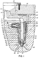
- Figure 1 is a partial sectional view of a portion of a multi-cavity injection molding system showing apparatus according to one embodiment of the invention,
- Figure 2 is a larger cut-away view showing the shaft of the torpedo seen in Figure 1, and
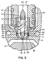
- Figure 3 is a similar view to Figure 2 showing another embodiment of the invention.
- Reference is first made to Figure 1 which shows a portion of a multi-cavity injection molding system having
several steel nozzles 10 to convey pressurized plastic melt through amelt passage 12 torespective gates 14 leading todifferent cavities 16 in themold 18. In this particular configuration, the mold includes acavity plate 20 andback plate 22 which are removably secured together bybolts 24. Other molds may include a variety of other plates or parts, depending upon the application. Themold 18 is cooled by pumping cooling water throughcooling conduits 26 extending in thecavity plate 20 and theback plate 22. An electrically heated steelmelt distribution manifold 28 is mounted between thecavity plate 20 andback plate 22 by a central locatingring 30 and insulative andresilient spacer members 32. Themelt distribution manifold 28 has acylindrical inlet portion 34 and is heated by an integralelectrical heating element 36. Aninsulative air space 38 is provided between theheated manifold 28 and the surrounding cooledcavity plate 20 andback plate 22. Themelt passage 12 extends from acentral inlet 40 in theinlet portion 34 of themanifold 28 and branches outward in themanifold 28 to eachnozzle 10 where it extends through acentral melt bore 42 and then through analigned opening 44 through atorpedo 46 to one of thegates 14 extending through agate insert 48 seated in themold 18 to acavity 16. - Each
nozzle 10 has an outer surface 50, arear end 52, and afront end 54. Thenozzle 10 is heated by an integralelectrical heating element 56 which extends around themelt bore 42 to anexternal terminal 58 to which electrical leads 60 from a power source are connected. Thenozzle 10 is seated in awell 62 in thecavity plate 20 with a cylindrical insulating and locatingflange 64 extending forwardly to a circular locatingshoulder 66 in thewell 62. Thus, aninsulative air space 68 is provided between theinner surface 70 of thewell 62 and the outer surface 50 of thenozzle 10 to provide thermal separation between the heatednozzle 10 and the surrounding cooledmold 18. - As best seen in Figure 2, the
nozzle 10 has aseat 72 with a threadedinner surface 74 extending around themelt bore 42 at itsfront end 54. In this embodiment, anopening 76 extends through themold 18 from thewell 62 to thecavity 16. Thesurface 78 ofopening 76 has a cylindricalrear portion 80 and an inwardly taperedforward portion 82. The gate insert 48 according to the invention is seated in theopening 76 with thegate 14 extending centrally therethrough to thecavity 16. Thegate insert 48 has arear end 84, afront surface 86 which faces thecavity 16 and anouter surface 88 which matches thesurface 78 of theopening 76 through themold 18. Thegate insert 48 is formed of a thermally conductive engineered ceramic such as silicon carbide. - The
torpedo 46 has an elongatedcentral shaft 90 according to the invention which is described in more detail below. The elongatedcentral shaft 90 extends longitudinally through anouter collar 92 with the opening 44 therebetween. In this embodiment, thecentral shaft 90 is connected to theouter collar 92 by a pair ofspiral blades 94 extending across theopening 44, but in other embodiments one or more other support members such as pins or straight fins can be used instead. Theouter collar 92 of thetorpedo 46 has a hexagon shapedintermediate portion 96 extending between acylindrical front portion 98 and a cylindricalrear portion 100 with a threadedouter surface 102. Therear portion 100 is screwed into theseat 72 extending around themelt bore 42 at thefront end 54 of thenozzle 10, and thenozzle 10 is received in thewell 62 with thefront portion 98 of theouter collar 86 seated in theopening 76 through themold 16. Screwing thetorpedo 46 into thenozzle 10 has the advantage that it is secured in place with a smallcircular gap 104 provided between theforward end 106 of theouter collar 86 and therear end 84 of thegate insert 48 to avoid damage to the gate insert 48 due to thermal expansion. In the embodiment, a hollowsteel spacer ring 108 having a circular cross-section is mounted in thegap 104 to retain thegate insert 48 in place until molding commences. During the first injection cycle, the remainder of thegap 104 fills with melt which solidifies due to contact with the cooledmold 18 and holds thegate insert 48 in place. As can be seen, thespacer ring 108 may be deformed by thermal expansion to become slightly oblong. Thetorpedo 46 is easily removed by applying a wrench to the hexagonalintermediate portion 96 of theouter collar 92. Thus, theouter collar 92 of thetorpedo 46 bridges theinsulative air space 68 extending between thefront end 54 of thenozzle 10 and themold 18 and prevents pressurized melt escaping into theair space 68. A seal is provided between theouter surface 110 of thefront portion 98 of theouter collar 92 and the surroundingcylindrical portion 80 of thesurface 78 of theopening 76. - The elongated
central shaft 90 of thetorpedo 46 according to the invention has an elongatedcentral portion 112 extending through anouter sleeve 114. Thespiral blades 94 extend outwardly from theouter sleeve 114 which, in this embodiment, is made of tool steel. In this embodiment, theouter sleeve 114 is press fitted around the elongatedcentral portion 112 to secure it in place extending from themelt bore 42 in alignment with thegate 14. Although thecentral portion 112 of thetorpedo shaft 90 is shown with a pointedfront tip 116 extending centrally into thegate 14 for hot tip gating, in another embodiment it may have an outwardly flared nose portion to provide fixed ring gating as described in the applicants' Canadian patent application serial no. 2,091,407 filed March 10, 1993 entitled "Injection Molding Torpedo Providing Fixed Ring Gate". As can be seen, thecentral portion 112 of thetorpedo shaft 90 extends rearwardly past therear end 118 of theouter sleeve 114 and has a pointedrear end 120 facing upstream into the melt flowing through themelt bore 42. In this embodiment, thecentral portion 112 of thetorpedo shaft 90 has an outwardly extendingcircular shoulder 122 which fits against therear end 118 of theouter sleeve 114 to ensure it is secured in place against the force from the melt flow. - While the
outer sleeve 114 of thetorpedo shaft 90 is formed of tool steel which is corrosion and abrasion resistant, the elongatedcentral portion 112 is formed of and engineered ceramic material such as silicon carbide which is very thermally conductive as well as being very corrosion and abrasion resistant. Other suitable engineered ceramic materials are boron carbide, silicon nitride, and zirconium oxide. This minimizes wear, particularly of the pointedfront tip 116 around which the melt flow is accelerated to flow through the constricted gate, but also provides for direct rapid response to thermal requirements in the gate area during the thermodynamic cycle of the molding sequence. This structure of thetorpedo shaft 90 provides the maximum exposure to the melt of the highly thermallyconductive material 112 in thegate 14 without requiring a protective coating of a lesser wear and corrosion resistant material. - A
thermocouple bore 124 extends radially inward into thetorpedo 46 through theouter collar 92 and one of thespiral blades 94 to thecentral portion 112 of theshaft 90. Athermocouple element 126 is received in thethermocouple bore 124 to accurately monitor the operating temperature. Thethermocouple element 126 extends rearwardly through theair space 68 and out through ahollow thermocouple tube 128. Thus, thethermocouple element 126 is easily removable, and in the event of leakage of melt into theair space 68, it will freeze off around thethermocouple element 126 in thethermocouple tube 128 to prevent leakage into the rest of the system. - In use, the injection molding system is assembled as shown in Figure 1. While only a
single cavity 16 has been shown for ease of illustration, it will be appreciated that themelt distribution manifold 28 normally has many more melt passage branches extending tonumerous cavities 16 depending on the application. Electrical power is applied to theheating element 36 in themanifold 28 and to theheating elements 56 in thenozzles 10 to heat them to a predetermined operating temperature. Heat from theheating element 56 in eachnozzle 10 is conducted forwardly through the elongatedcentral portion 112 of thetorpedo shaft 90 to thepointed front tip 116 extending into thegate 14. Pressurized melt from a molding machine (not shown) is then injected into themelt passage 12 through thecommon inlet 40 according to a predetermined cycle in a conventional manner. The pressurized melt flows through the melt bore 42 of each nozzle, through theopening 44 between thespiral blades 94 of thetorpedo 46, and through thegate 14 to fill thecavity 16. The flow between the fixedspiral blades 94 imparts a swirling motion to the melt. This swirling motion is accelerated as the melt approaches thegate 14 and results in the melt flowing outward in thecavity 16 near thegate 14 with a curving motion. This avoids unidirectional molecular orientation of the melt, at least adjacent the gate, and provides a stronger product in the gate area. After thecavities 16 are filled, injection pressure is held momentarily to pack and then released. After a short cooling period, the mold is opened to eject the molded products. After ejection, the mold is closed and injection pressure is reapplied to refill thecavities 16. This injection cycle is continuously repeated with a frequency dependent on the size and shape of thecavities 16 and the type of material being molded. - During this repetitious injection cycle, heat is continuously transferred by the
torpedo shaft 90 according to a thermodynamic cycle to control the viscosity of the melt in thegate 14. In some applications, sufficient heat is produced in the melt by the screw barrel of the injection machine and by shear as it is forced through thetorpedo 46 and the constrictedgate 14. Of course, the amount of heat generated by the melt flow can be varied by changing its velocity. In other applications, theheating elements 56 in thenozzles 10 are also used after start-up to provide additional heat to the melt. During injection, heat is transferred forwardly through the elongatedcentral portion 112 of thetorpedo shaft 90 to prevent excessive solidification of the melt in the area of thegate 14. When injection pressure is reapplied during injection, thecentral portion 112 of thetorpedo shaft 90 conducts excess heat which is generated by the friction of the melt flowing through the constricted area of thegate 14 rearwardly to avoid stringing and drooling of the melt when the mold opens for ejection. After the melt has stopped flowing, solidification in thegate 14 is enhanced by the removal of excess friction heat rearwardly through thecentral portion 112 of thetorpedo shaft 90. The size of the pointedfront tip 116 of thecentral portion 112 of thetorpedo shaft 90 which extends into thegate 14 is necessarily limited by the size of thegate 14 and the area required for the melt flow. Thus, the thermodynamic cycle is enhanced by this torpedo shaft structure which allows more of the highly conductive material to extend into thegate 14 without any of the space being taken up by a protective outer casing. The improved heat transfer provides faster solidification and reduces melt sticking to the molded product when the mold opens for ejection. Thus, cycle time is reduced and cosmetically cleaner gates are provided. - Reference is now made to Figure 3 to briefly describe another embodiment of the invention. As most of the elements are the same as those described above, common elements are described and illustrated using the same reference numerals. In this embodiment, the
opening 76 extending through themold 18 from the well has a cylindricalfront portion 130 which is smaller in diameter than the cylindricalrear portion 80. Thus, a circular shoulder 132 is provided, against which the matchingouter surface 88 of thegate insert 48 abuts. In both embodiments, the area of thefront surface 86 of thegate insert 48 facing thecavity 16 does not exceed the cross-sectional area of the melt bore 42. Thus, the rearward force from the pressure of the injected melt in thecavity 16 is not greater than the force from the melt in thegate insert 48, so thegate insert 48 is retained in place. - While the description of the injection molding apparatus according to the invention has been given with respect to a preferred embodiment, it will be evident that various other modifications are possible without departing from the scope of the claims.
Claims (13)
- An injection molding apparatus comprising a heated nozzle (10) seated in a well (62) in a mold (18) and a torpedo (46) to convey melt to a gate (14), the nozzle having a rear end (52), a front end (54), a melt bore (42) extending longitudinally therethrough from the rear end (52) to the front end (54) in alignment with the gate, and a seat (72) extending around the melt bore (42) at the front end (54) of the nozzle (10), the torpedo having an outer collar (92), an elongated shaft (90) extending centrally through the outer collar (92) with an opening extending through the torpedo (46) between the central shaft (90) and the outer collar (92), and at least one support member (94) extending across the opening between the central shaft (90) and the outer collar (92), the outer collar (92) being removably received in the seat at the front end (54) of the nozzle (10) with the opening through the torpedo (46) aligned with the melt bore (42) through the nozzle (10) and the central shaft (90) of the torpedo aligned (46) with the gate (14), the apparatus being characterized in that
the elongated central shaft (90) of the torpedo (46) has an elongated central portion (112) extending through an outer sleeve (114), the at least one support member (94) extends outwardly from the outer sleeve (114) to the outer collar (92), the central portion (112) is secured in the outer sleeve (114) to extend from the melt bore (42) in alignment with the gate (14), and the central portion (112) of the elongated shaft (90) of the torpedo is formed of a thermally conductive engineered ceramic material. - Injection molding apparatus as claimed in claim 1 wherein the central portion (112) of the elongated shaft (90) of the torpedo has a pointed front tip (116) extending centrally into the gate.
- Injection molding apparatus as claimed in claim 2 wherein the outer collar (92), at least one support member (94), and the outer sleeve (114) of the elongated shaft of the torpedo are formed of steel.
- Injection molding apparatus as claimed in claim 3 wherein the at least one support member (94) is at least one blade extending between the outer collar (92) and the outer sleeve (114) of the elongated shaft.
- Injection molding apparatus as claimed in claim 4 wherein the outer sleeve (114) of the elongated shaft of the torpedo has a rear end, and the central portion (112) of the elongated shaft of the torpedo extends rearwardly past the rear end (118) of the outer sleeve and has an outwardly extending circular shoulder (122) abutting against the rear end (118) of the outer sleeve.
- Injection molding apparatus as claimed in claim 4 wherein the outer sleeve (114) of the longitudinal shaft of the torpedo is securely press fitted around the central portion.
- Injection molding apparatus as claimed in claim 4 wherein the engineered ceramic material is silicon carbide.
- Injection molding apparatus as claimed in claim 4 wherein an opening extends centrally through the mold (18) from the well (62) to a cavity (16), the well (62) in the mold has an inner surface, the nozzle (10) is seated in the well (62) in the mold with an insulative air space extending between the outer surface of the nozzle and the inner surface of the well, the outer collar (114) of the torpedo has a cylindrical rear portion (100) and a cylindrical front portion (98), the cylindrical rear portion (100) of the outer collar (92) being removably received in the seat (72) at the front end of the nozzle (18) and the cylindrical front portion (98) of the outer collar being received in the opening extending from the well (62) through the mold (18), whereby the outer collar (114) bridges the insulative air space extending between the nozzle (10) and the mold (18), and a gate insert (48) is seated in the opening extending from the well (62) through the mold (18), the gate insert (48) has the gate extending therethrough to the cavity.
- Injection molding apparatus as claimed in claim 8 wherein the gate insert (48) is formed of a thermally conductive engineered ceramic material.
- Injection molding apparatus as claimed in claim 9 wherein the engineered ceramic material is silicon carbide.
- Injection molding apparatus as claimed in claim 9 wherein the gate insert (48) has a rear end spaced a predetermined distance from the front portion of the torpedo (46) to provide a circular gap (104) therebetween, and a spacer ring (108) is mounted in the gap between the rear end of the gate insert (48) and the front portion of the torpedo.
- Injection molding apparatus as claimed in claim 11 wherein the spacer ring (108) has a circular cross-section.
- Injection molding apparatus as claimed in claim 12 wherein the spacer ring (108) is formed of steel.
Applications Claiming Priority (2)
| Application Number | Priority Date | Filing Date | Title |
|---|---|---|---|
| CA002093588A CA2093588C (en) | 1993-04-07 | 1993-04-07 | Injection molding torpedo with shaft having ceramic central portion |
| CA2093588 | 1993-04-07 |
Publications (2)
| Publication Number | Publication Date |
|---|---|
| EP0620096A1 EP0620096A1 (en) | 1994-10-19 |
| EP0620096B1 true EP0620096B1 (en) | 1997-07-23 |
Family
ID=4151431
Family Applications (1)
| Application Number | Title | Priority Date | Filing Date |
|---|---|---|---|
| EP94105338A Expired - Lifetime EP0620096B1 (en) | 1993-04-07 | 1994-04-06 | Injection molding torpedo with shaft having ceramic central portion |
Country Status (6)
| Country | Link |
|---|---|
| EP (1) | EP0620096B1 (en) |
| JP (1) | JP3461901B2 (en) |
| CN (1) | CN1094353A (en) |
| AT (1) | ATE155729T1 (en) |
| CA (1) | CA2093588C (en) |
| DE (2) | DE69404360T2 (en) |
Families Citing this family (8)
| Publication number | Priority date | Publication date | Assignee | Title |
|---|---|---|---|---|
| US5683731A (en) * | 1995-12-11 | 1997-11-04 | Husky Injection Molding Systems Ltd. | Melt flow redistributor |
| SE518906C2 (en) * | 1997-12-05 | 2002-12-03 | Helldin Ab N | Injection molding device |
| DE102004032336B3 (en) * | 2004-07-02 | 2005-11-10 | Sfr Formenbau Gmbh | Injection nozzle for feeding plastic into molding tool has torpedo extending into annular melt channel to the tip and conductive metal insert inside chamber within the nozzle shaft and tip |
| DE102004038056B3 (en) * | 2004-08-05 | 2006-03-09 | Otto Männer Innovation GmbH | hot runner nozzle |
| DE202008007918U1 (en) * | 2008-06-16 | 2009-11-19 | Günther Heisskanaltechnik Gmbh | Injection molding nozzle for an injection mold |
| JP2015098147A (en) * | 2013-11-20 | 2015-05-28 | 小島プレス工業株式会社 | Injection molding machine |
| CN108127896A (en) * | 2017-12-08 | 2018-06-08 | 泉州精达皮塑五金工艺有限公司 | A kind of note of PET plastic blows manufacture craft and its product |
| CN110789052B (en) * | 2019-06-18 | 2021-06-04 | 杭州德耐机械有限公司 | Controllable high-precision mold injection molding machine |
Family Cites Families (8)
| Publication number | Priority date | Publication date | Assignee | Title |
|---|---|---|---|---|
| CA1190019A (en) * | 1982-07-12 | 1985-07-09 | Jobst U. Gellert | Injection molding hot tip seal |
| US4652230A (en) * | 1985-05-06 | 1987-03-24 | Osuna Diaz J M | Injection molding nozzle |
| DE3529881A1 (en) * | 1985-08-21 | 1987-02-26 | Albers August | Temperature-controllable sprue runner for plastic injection moulds |
| CA1265907A (en) * | 1987-02-17 | 1990-02-20 | Jobst U. Gellert | Injection molding system having manifold with side mounted nozzles and method |
| US4771164A (en) * | 1987-04-01 | 1988-09-13 | Gellert Jobst U | Injection molding nozzle and method |
| CA1261577A (en) * | 1988-09-30 | 1989-09-26 | Jobst U. Gellert | Injection molding nozzle with replaceable gate insert |
| US5098280A (en) * | 1990-09-26 | 1992-03-24 | Panos Trakas | Sprue bushing with displaceable gating needle |
| CA2057438C (en) * | 1991-12-11 | 2005-02-08 | Jobst Ulrich Gellert | Injection molding sealing collar with a central hot tip shaft |
-
1993
- 1993-04-07 CA CA002093588A patent/CA2093588C/en not_active Expired - Lifetime
-
1994
- 1994-03-18 CN CN94103429.1A patent/CN1094353A/en active Pending
- 1994-04-01 JP JP06494994A patent/JP3461901B2/en not_active Expired - Lifetime
- 1994-04-06 AT AT94105338T patent/ATE155729T1/en not_active IP Right Cessation
- 1994-04-06 DE DE69404360T patent/DE69404360T2/en not_active Expired - Lifetime
- 1994-04-06 DE DE4411878A patent/DE4411878B4/en not_active Expired - Lifetime
- 1994-04-06 EP EP94105338A patent/EP0620096B1/en not_active Expired - Lifetime
Also Published As
| Publication number | Publication date |
|---|---|
| ATE155729T1 (en) | 1997-08-15 |
| CA2093588A1 (en) | 1994-10-08 |
| CA2093588C (en) | 2001-07-24 |
| JP3461901B2 (en) | 2003-10-27 |
| EP0620096A1 (en) | 1994-10-19 |
| DE69404360T2 (en) | 1997-11-13 |
| DE4411878A1 (en) | 1994-10-13 |
| DE69404360D1 (en) | 1997-09-04 |
| DE4411878B4 (en) | 2005-12-01 |
| JPH06304971A (en) | 1994-11-01 |
| CN1094353A (en) | 1994-11-02 |
Similar Documents
| Publication | Publication Date | Title |
|---|---|---|
| EP0681900B1 (en) | Injection molding nozzle with two removable inserts | |
| US5268184A (en) | Injection molding nozzle with removable forward member | |
| US5028227A (en) | Injection molding nozzle with replaceable gate insert | |
| US5284436A (en) | Injection molding torpedo with shaft having ceramic central portion | |
| US5334008A (en) | Injection molding nozzle insert with valve member locating blades | |
| US6302680B1 (en) | Injection molding apparatus with removable nozzle seal | |
| US5427519A (en) | Injection molding nozzle with helical cooling conduit | |
| US5405258A (en) | Injection molding torpedo with thermocouple bore | |
| CA2057438C (en) | Injection molding sealing collar with a central hot tip shaft | |
| US5318434A (en) | Injection molding torpedo providing a fixed ring gate | |
| EP0337454B1 (en) | Injection molding system with nozzle in tandem | |
| EP0523549A2 (en) | Injection molding manifold with removable inserts | |
| EP0620096B1 (en) | Injection molding torpedo with shaft having ceramic central portion | |
| EP0380748B1 (en) | Sprue gated stack injection molding system | |
| EP0535616B1 (en) | Injection molding apparatus with angled tip probe | |
| EP0633118B1 (en) | Two-piece injection molding nozzle seal | |
| CA2037186C (en) | Injection molding probe with a longitudinal thermocouple bore and off center heating element | |
| CA1261577A (en) | Injection molding nozzle with replaceable gate insert | |
| CA2078890A1 (en) | Injection molding nozzle with thermocouple receiving torpedo |
Legal Events
| Date | Code | Title | Description |
|---|---|---|---|
| PUAI | Public reference made under article 153(3) epc to a published international application that has entered the european phase |
Free format text: ORIGINAL CODE: 0009012 |
|
| AK | Designated contracting states |
Kind code of ref document: A1 Designated state(s): AT BE CH DE DK ES FR GB IE IT LI LU NL PT SE |
|
| 17P | Request for examination filed |
Effective date: 19950419 |
|
| GRAG | Despatch of communication of intention to grant |
Free format text: ORIGINAL CODE: EPIDOS AGRA |
|
| 17Q | First examination report despatched |
Effective date: 19960618 |
|
| GRAH | Despatch of communication of intention to grant a patent |
Free format text: ORIGINAL CODE: EPIDOS IGRA |
|
| GRAH | Despatch of communication of intention to grant a patent |
Free format text: ORIGINAL CODE: EPIDOS IGRA |
|
| GRAA | (expected) grant |
Free format text: ORIGINAL CODE: 0009210 |
|
| AK | Designated contracting states |
Kind code of ref document: B1 Designated state(s): AT BE CH DE DK ES FR GB IE IT LI LU NL PT SE |
|
| PG25 | Lapsed in a contracting state [announced via postgrant information from national office to epo] |
Ref country code: IT Free format text: LAPSE BECAUSE OF FAILURE TO SUBMIT A TRANSLATION OF THE DESCRIPTION OR TO PAY THE FEE WITHIN THE PRESCRIBED TIME-LIMIT;WARNING: LAPSES OF ITALIAN PATENTS WITH EFFECTIVE DATE BEFORE 2007 MAY HAVE OCCURRED AT ANY TIME BEFORE 2007. THE CORRECT EFFECTIVE DATE MAY BE DIFFERENT FROM THE ONE RECORDED. Effective date: 19970723 Ref country code: FR Effective date: 19970723 Ref country code: ES Free format text: THE PATENT HAS BEEN ANNULLED BY A DECISION OF A NATIONAL AUTHORITY Effective date: 19970723 Ref country code: DK Effective date: 19970723 Ref country code: BE Effective date: 19970723 Ref country code: AT Effective date: 19970723 |
|
| REF | Corresponds to: |
Ref document number: 155729 Country of ref document: AT Date of ref document: 19970815 Kind code of ref document: T |
|
| REG | Reference to a national code |
Ref country code: CH Ref legal event code: NV Representative=s name: PATENTANWALTSBUERO JEAN HUNZIKER Ref country code: CH Ref legal event code: EP |
|
| REF | Corresponds to: |
Ref document number: 69404360 Country of ref document: DE Date of ref document: 19970904 |
|
| PG25 | Lapsed in a contracting state [announced via postgrant information from national office to epo] |
Ref country code: SE Effective date: 19971023 |
|
| PG25 | Lapsed in a contracting state [announced via postgrant information from national office to epo] |
Ref country code: PT Effective date: 19971031 |
|
| EN | Fr: translation not filed | ||
| PG25 | Lapsed in a contracting state [announced via postgrant information from national office to epo] |
Ref country code: IE Free format text: LAPSE BECAUSE OF NON-PAYMENT OF DUE FEES Effective date: 19980406 Ref country code: GB Free format text: LAPSE BECAUSE OF NON-PAYMENT OF DUE FEES Effective date: 19980406 |
|
| PLBE | No opposition filed within time limit |
Free format text: ORIGINAL CODE: 0009261 |
|
| STAA | Information on the status of an ep patent application or granted ep patent |
Free format text: STATUS: NO OPPOSITION FILED WITHIN TIME LIMIT |
|
| 26N | No opposition filed | ||
| GBPC | Gb: european patent ceased through non-payment of renewal fee |
Effective date: 19980406 |
|
| REG | Reference to a national code |
Ref country code: CH Ref legal event code: PUE Owner name: MOLD-MASTERS (2007) LIMITED Free format text: GELLERT, JOBST ULRICH#233 ARMSTRONG AVENUE#GEORGETOWN ONTARIO L7G 4X5 (CA) -TRANSFER TO- MOLD-MASTERS (2007) LIMITED#233 ARMSTRONG AVENUE#GEORGETOWN ON L7G4X5 (CA) |
|
| NLS | Nl: assignments of ep-patents |
Owner name: MOLD-MASTERS (2007) LIMITED Effective date: 20080610 |
|
| PGFP | Annual fee paid to national office [announced via postgrant information from national office to epo] |
Ref country code: CH Payment date: 20130326 Year of fee payment: 20 Ref country code: LU Payment date: 20130326 Year of fee payment: 20 |
|
| PGFP | Annual fee paid to national office [announced via postgrant information from national office to epo] |
Ref country code: DE Payment date: 20130322 Year of fee payment: 20 |
|
| PGFP | Annual fee paid to national office [announced via postgrant information from national office to epo] |
Ref country code: NL Payment date: 20130322 Year of fee payment: 20 |
|
| REG | Reference to a national code |
Ref country code: DE Ref legal event code: R071 Ref document number: 69404360 Country of ref document: DE |
|
| REG | Reference to a national code |
Ref country code: CH Ref legal event code: PL |
|
| REG | Reference to a national code |
Ref country code: NL Ref legal event code: V4 Effective date: 20140406 |
|
| PG25 | Lapsed in a contracting state [announced via postgrant information from national office to epo] |
Ref country code: DE Free format text: LAPSE BECAUSE OF EXPIRATION OF PROTECTION Effective date: 20140408 |