EP0620035A1 - Pressure swing adsorption/desorption process with multiple countercurrent de-pressurization steps - Google Patents
Pressure swing adsorption/desorption process with multiple countercurrent de-pressurization steps Download PDFInfo
- Publication number
- EP0620035A1 EP0620035A1 EP93302966A EP93302966A EP0620035A1 EP 0620035 A1 EP0620035 A1 EP 0620035A1 EP 93302966 A EP93302966 A EP 93302966A EP 93302966 A EP93302966 A EP 93302966A EP 0620035 A1 EP0620035 A1 EP 0620035A1
- Authority
- EP
- European Patent Office
- Prior art keywords
- pressure
- component
- desorption
- adsorption
- countercurrent
- Prior art date
- Legal status (The legal status is an assumption and is not a legal conclusion. Google has not performed a legal analysis and makes no representation as to the accuracy of the status listed.)
- Withdrawn
Links
Images

Classifications
-
- B—PERFORMING OPERATIONS; TRANSPORTING
- B01—PHYSICAL OR CHEMICAL PROCESSES OR APPARATUS IN GENERAL
- B01D—SEPARATION
- B01D53/00—Separation of gases or vapours; Recovering vapours of volatile solvents from gases; Chemical or biological purification of waste gases, e.g. engine exhaust gases, smoke, fumes, flue gases, aerosols
- B01D53/02—Separation of gases or vapours; Recovering vapours of volatile solvents from gases; Chemical or biological purification of waste gases, e.g. engine exhaust gases, smoke, fumes, flue gases, aerosols by adsorption, e.g. preparative gas chromatography
- B01D53/04—Separation of gases or vapours; Recovering vapours of volatile solvents from gases; Chemical or biological purification of waste gases, e.g. engine exhaust gases, smoke, fumes, flue gases, aerosols by adsorption, e.g. preparative gas chromatography with stationary adsorbents
- B01D53/047—Pressure swing adsorption
-
- B—PERFORMING OPERATIONS; TRANSPORTING
- B01—PHYSICAL OR CHEMICAL PROCESSES OR APPARATUS IN GENERAL
- B01D—SEPARATION
- B01D2256/00—Main component in the product gas stream after treatment
- B01D2256/10—Nitrogen
-
- B—PERFORMING OPERATIONS; TRANSPORTING
- B01—PHYSICAL OR CHEMICAL PROCESSES OR APPARATUS IN GENERAL
- B01D—SEPARATION
- B01D2256/00—Main component in the product gas stream after treatment
- B01D2256/16—Hydrogen
-
- B—PERFORMING OPERATIONS; TRANSPORTING
- B01—PHYSICAL OR CHEMICAL PROCESSES OR APPARATUS IN GENERAL
- B01D—SEPARATION
- B01D2256/00—Main component in the product gas stream after treatment
- B01D2256/24—Hydrocarbons
-
- B—PERFORMING OPERATIONS; TRANSPORTING
- B01—PHYSICAL OR CHEMICAL PROCESSES OR APPARATUS IN GENERAL
- B01D—SEPARATION
- B01D2257/00—Components to be removed
- B01D2257/10—Single element gases other than halogens
- B01D2257/102—Nitrogen
-
- B—PERFORMING OPERATIONS; TRANSPORTING
- B01—PHYSICAL OR CHEMICAL PROCESSES OR APPARATUS IN GENERAL
- B01D—SEPARATION
- B01D2257/00—Components to be removed
- B01D2257/30—Sulfur compounds
- B01D2257/304—Hydrogen sulfide
-
- B—PERFORMING OPERATIONS; TRANSPORTING
- B01—PHYSICAL OR CHEMICAL PROCESSES OR APPARATUS IN GENERAL
- B01D—SEPARATION
- B01D2257/00—Components to be removed
- B01D2257/40—Nitrogen compounds
- B01D2257/406—Ammonia
-
- B—PERFORMING OPERATIONS; TRANSPORTING
- B01—PHYSICAL OR CHEMICAL PROCESSES OR APPARATUS IN GENERAL
- B01D—SEPARATION
- B01D2257/00—Components to be removed
- B01D2257/50—Carbon oxides
- B01D2257/502—Carbon monoxide
-
- B—PERFORMING OPERATIONS; TRANSPORTING
- B01—PHYSICAL OR CHEMICAL PROCESSES OR APPARATUS IN GENERAL
- B01D—SEPARATION
- B01D2257/00—Components to be removed
- B01D2257/50—Carbon oxides
- B01D2257/504—Carbon dioxide
-
- B—PERFORMING OPERATIONS; TRANSPORTING
- B01—PHYSICAL OR CHEMICAL PROCESSES OR APPARATUS IN GENERAL
- B01D—SEPARATION
- B01D2257/00—Components to be removed
- B01D2257/70—Organic compounds not provided for in groups B01D2257/00 - B01D2257/602
- B01D2257/702—Hydrocarbons
- B01D2257/7022—Aliphatic hydrocarbons
- B01D2257/7025—Methane
-
- B—PERFORMING OPERATIONS; TRANSPORTING
- B01—PHYSICAL OR CHEMICAL PROCESSES OR APPARATUS IN GENERAL
- B01D—SEPARATION
- B01D2257/00—Components to be removed
- B01D2257/80—Water
-
- B—PERFORMING OPERATIONS; TRANSPORTING
- B01—PHYSICAL OR CHEMICAL PROCESSES OR APPARATUS IN GENERAL
- B01D—SEPARATION
- B01D2259/00—Type of treatment
- B01D2259/40—Further details for adsorption processes and devices
- B01D2259/40011—Methods relating to the process cycle in pressure or temperature swing adsorption
- B01D2259/40013—Pressurization
- B01D2259/40015—Pressurization with two sub-steps
-
- B—PERFORMING OPERATIONS; TRANSPORTING
- B01—PHYSICAL OR CHEMICAL PROCESSES OR APPARATUS IN GENERAL
- B01D—SEPARATION
- B01D2259/00—Type of treatment
- B01D2259/40—Further details for adsorption processes and devices
- B01D2259/40011—Methods relating to the process cycle in pressure or temperature swing adsorption
- B01D2259/40028—Depressurization
- B01D2259/4003—Depressurization with two sub-steps
-
- B—PERFORMING OPERATIONS; TRANSPORTING
- B01—PHYSICAL OR CHEMICAL PROCESSES OR APPARATUS IN GENERAL
- B01D—SEPARATION
- B01D2259/00—Type of treatment
- B01D2259/40—Further details for adsorption processes and devices
- B01D2259/40011—Methods relating to the process cycle in pressure or temperature swing adsorption
- B01D2259/40028—Depressurization
- B01D2259/40033—Depressurization with more than three sub-steps
-
- B—PERFORMING OPERATIONS; TRANSPORTING
- B01—PHYSICAL OR CHEMICAL PROCESSES OR APPARATUS IN GENERAL
- B01D—SEPARATION
- B01D2259/00—Type of treatment
- B01D2259/40—Further details for adsorption processes and devices
- B01D2259/40011—Methods relating to the process cycle in pressure or temperature swing adsorption
- B01D2259/40035—Equalization
- B01D2259/40037—Equalization with two sub-steps
-
- B—PERFORMING OPERATIONS; TRANSPORTING
- B01—PHYSICAL OR CHEMICAL PROCESSES OR APPARATUS IN GENERAL
- B01D—SEPARATION
- B01D2259/00—Type of treatment
- B01D2259/40—Further details for adsorption processes and devices
- B01D2259/40011—Methods relating to the process cycle in pressure or temperature swing adsorption
- B01D2259/40035—Equalization
- B01D2259/40041—Equalization with more than three sub-steps
-
- B—PERFORMING OPERATIONS; TRANSPORTING
- B01—PHYSICAL OR CHEMICAL PROCESSES OR APPARATUS IN GENERAL
- B01D—SEPARATION
- B01D2259/00—Type of treatment
- B01D2259/40—Further details for adsorption processes and devices
- B01D2259/40011—Methods relating to the process cycle in pressure or temperature swing adsorption
- B01D2259/40043—Purging
- B01D2259/4005—Nature of purge gas
- B01D2259/40052—Recycled product or process gas
-
- B—PERFORMING OPERATIONS; TRANSPORTING
- B01—PHYSICAL OR CHEMICAL PROCESSES OR APPARATUS IN GENERAL
- B01D—SEPARATION
- B01D2259/00—Type of treatment
- B01D2259/40—Further details for adsorption processes and devices
- B01D2259/40011—Methods relating to the process cycle in pressure or temperature swing adsorption
- B01D2259/40058—Number of sequence steps, including sub-steps, per cycle
- B01D2259/40066—Six
-
- B—PERFORMING OPERATIONS; TRANSPORTING
- B01—PHYSICAL OR CHEMICAL PROCESSES OR APPARATUS IN GENERAL
- B01D—SEPARATION
- B01D2259/00—Type of treatment
- B01D2259/40—Further details for adsorption processes and devices
- B01D2259/40011—Methods relating to the process cycle in pressure or temperature swing adsorption
- B01D2259/40058—Number of sequence steps, including sub-steps, per cycle
- B01D2259/40067—Seven
-
- B—PERFORMING OPERATIONS; TRANSPORTING
- B01—PHYSICAL OR CHEMICAL PROCESSES OR APPARATUS IN GENERAL
- B01D—SEPARATION
- B01D2259/00—Type of treatment
- B01D2259/40—Further details for adsorption processes and devices
- B01D2259/40011—Methods relating to the process cycle in pressure or temperature swing adsorption
- B01D2259/40058—Number of sequence steps, including sub-steps, per cycle
- B01D2259/40069—Eight
-
- B—PERFORMING OPERATIONS; TRANSPORTING
- B01—PHYSICAL OR CHEMICAL PROCESSES OR APPARATUS IN GENERAL
- B01D—SEPARATION
- B01D2259/00—Type of treatment
- B01D2259/40—Further details for adsorption processes and devices
- B01D2259/40011—Methods relating to the process cycle in pressure or temperature swing adsorption
- B01D2259/40058—Number of sequence steps, including sub-steps, per cycle
- B01D2259/40075—More than ten
-
- B—PERFORMING OPERATIONS; TRANSPORTING
- B01—PHYSICAL OR CHEMICAL PROCESSES OR APPARATUS IN GENERAL
- B01D—SEPARATION
- B01D2259/00—Type of treatment
- B01D2259/40—Further details for adsorption processes and devices
- B01D2259/40011—Methods relating to the process cycle in pressure or temperature swing adsorption
- B01D2259/40077—Direction of flow
- B01D2259/40079—Co-current
-
- B—PERFORMING OPERATIONS; TRANSPORTING
- B01—PHYSICAL OR CHEMICAL PROCESSES OR APPARATUS IN GENERAL
- B01D—SEPARATION
- B01D2259/00—Type of treatment
- B01D2259/40—Further details for adsorption processes and devices
- B01D2259/40011—Methods relating to the process cycle in pressure or temperature swing adsorption
- B01D2259/40077—Direction of flow
- B01D2259/40081—Counter-current
-
- B—PERFORMING OPERATIONS; TRANSPORTING
- B01—PHYSICAL OR CHEMICAL PROCESSES OR APPARATUS IN GENERAL
- B01D—SEPARATION
- B01D2259/00—Type of treatment
- B01D2259/40—Further details for adsorption processes and devices
- B01D2259/404—Further details for adsorption processes and devices using four beds
-
- B—PERFORMING OPERATIONS; TRANSPORTING
- B01—PHYSICAL OR CHEMICAL PROCESSES OR APPARATUS IN GENERAL
- B01D—SEPARATION
- B01D2259/00—Type of treatment
- B01D2259/40—Further details for adsorption processes and devices
- B01D2259/406—Further details for adsorption processes and devices using more than four beds
- B01D2259/4067—Further details for adsorption processes and devices using more than four beds using ten beds
-
- B—PERFORMING OPERATIONS; TRANSPORTING
- B01—PHYSICAL OR CHEMICAL PROCESSES OR APPARATUS IN GENERAL
- B01D—SEPARATION
- B01D2259/00—Type of treatment
- B01D2259/40—Further details for adsorption processes and devices
- B01D2259/406—Further details for adsorption processes and devices using more than four beds
- B01D2259/4068—Further details for adsorption processes and devices using more than four beds using more than ten beds
-
- B—PERFORMING OPERATIONS; TRANSPORTING
- B01—PHYSICAL OR CHEMICAL PROCESSES OR APPARATUS IN GENERAL
- B01D—SEPARATION
- B01D53/00—Separation of gases or vapours; Recovering vapours of volatile solvents from gases; Chemical or biological purification of waste gases, e.g. engine exhaust gases, smoke, fumes, flue gases, aerosols
- B01D53/02—Separation of gases or vapours; Recovering vapours of volatile solvents from gases; Chemical or biological purification of waste gases, e.g. engine exhaust gases, smoke, fumes, flue gases, aerosols by adsorption, e.g. preparative gas chromatography
- B01D53/04—Separation of gases or vapours; Recovering vapours of volatile solvents from gases; Chemical or biological purification of waste gases, e.g. engine exhaust gases, smoke, fumes, flue gases, aerosols by adsorption, e.g. preparative gas chromatography with stationary adsorbents
- B01D53/047—Pressure swing adsorption
- B01D53/0476—Vacuum pressure swing adsorption
-
- B—PERFORMING OPERATIONS; TRANSPORTING
- B01—PHYSICAL OR CHEMICAL PROCESSES OR APPARATUS IN GENERAL
- B01D—SEPARATION
- B01D53/00—Separation of gases or vapours; Recovering vapours of volatile solvents from gases; Chemical or biological purification of waste gases, e.g. engine exhaust gases, smoke, fumes, flue gases, aerosols
- B01D53/26—Drying gases or vapours
- B01D53/261—Drying gases or vapours by adsorption
-
- Y—GENERAL TAGGING OF NEW TECHNOLOGICAL DEVELOPMENTS; GENERAL TAGGING OF CROSS-SECTIONAL TECHNOLOGIES SPANNING OVER SEVERAL SECTIONS OF THE IPC; TECHNICAL SUBJECTS COVERED BY FORMER USPC CROSS-REFERENCE ART COLLECTIONS [XRACs] AND DIGESTS
- Y02—TECHNOLOGIES OR APPLICATIONS FOR MITIGATION OR ADAPTATION AGAINST CLIMATE CHANGE
- Y02C—CAPTURE, STORAGE, SEQUESTRATION OR DISPOSAL OF GREENHOUSE GASES [GHG]
- Y02C20/00—Capture or disposal of greenhouse gases
- Y02C20/20—Capture or disposal of greenhouse gases of methane
-
- Y—GENERAL TAGGING OF NEW TECHNOLOGICAL DEVELOPMENTS; GENERAL TAGGING OF CROSS-SECTIONAL TECHNOLOGIES SPANNING OVER SEVERAL SECTIONS OF THE IPC; TECHNICAL SUBJECTS COVERED BY FORMER USPC CROSS-REFERENCE ART COLLECTIONS [XRACs] AND DIGESTS
- Y02—TECHNOLOGIES OR APPLICATIONS FOR MITIGATION OR ADAPTATION AGAINST CLIMATE CHANGE
- Y02C—CAPTURE, STORAGE, SEQUESTRATION OR DISPOSAL OF GREENHOUSE GASES [GHG]
- Y02C20/00—Capture or disposal of greenhouse gases
- Y02C20/40—Capture or disposal of greenhouse gases of CO2
Definitions
- the present invention generally relates to pressure swing adsorption (PSA) processes and more particularly to improved PSA processes for the separation or purification of gases wherein multiple countercurrent depressurization steps are employed in conjunction with a countercurrent purge step.
- PSA pressure swing adsorption
- PSA processes provide an efficient and economical means for separating a multi-component gas stream containing at least two gases having different adsorption characteristics.
- the more strongly adsorbed gas can be an impurity which is removed from the less strongly adsorbed gas which is taken off as product, or, the more strongly adsorbed gas can be the desired product which is separated from the less strongly adsorbed gas.
- carbon monoxide and light hydrocarbons can be removed from a hydrogen-containing feedstream to produce a purified (99+ %) hydrogen stream for a hydrocracking or other catalytic process where these impurities could adversely affect the catalyst or the reaction.
- more strongly adsorbed gases, such as ethylene can be recovered from a feedstream to produce an ethylene-rich product.
- a multi component gas is typically passed to at least one of a plurality of adsorption zones at an elevated pressure effective to adsorb at least one component, i.e. the more strongly adsorbed components, while at least one other component passes through, i.e. the less strongly adsorbed components.
- the passing of feedstream to the adsorber is terminated and the adsorption zone is depressurized by one or more cocurrent depressurization steps wherein the pressure is reduced to a defined level which permits the separated, less strongly adsorbed component or components remaining in the adsorption zone to be drawn off without significant concentration of the more strongly adsorbed components.
- the adsorption zone is depressurized by a countercurrent depressurization step wherein the pressure in the adsorption zone is further reduced by withdrawing desorbed gas countercurrently to the direction of the feedstream. Finally, the adsorption zone is purged and repressurized.
- PSA processing is disclosed in US-A-3,430,418; US-A-3,564,816 and in US-A-3,986,849 and described in these patents, the contents of which are incorporated herein by reference, the PSA process is generally carried out in a sequential processing cycle that includes each bed of the PSA system.
- the more strongly adsorbed components i.e., the adsorbate
- the more strongly adsorbed components are removed from the adsorber bed by countercurrently depressurizing the adsorber bed to a desorption pressure.
- Lower desorption pressures are preferred in order to provide more complete removal of the adsorbate during the desorption step.
- Lower desorption pressures can also provide a greater capacity differential between adsorption and desorption conditions and thus increase the capacity of the process.
- very low desorption pressures i.e., below atmospheric pressure, are not often used because of the technical complexities and cost associated therewith, e.g., vacuum pumping and the like.
- the desorption effluent stream also known as tail gas
- a pressure suitable for feeding into a fuel gas header e.g., 20-100 psia (138 to 690 kPa).
- the discharge pressure is typically maintained at or higher than the fuel gas pressure.
- PSA hydrogen processes typically employ a desorption pressure of greater than or equal to the fuel gas pressure.
- EP-B-15413 discloses a pressure swing adsorption process which employes a two stage countercurtent desorption step for the removal of adsorbed components which can achieve sub-atmospheric pressure.
- the patent discloses that the desorption pressures are produced with the aid of jet devices, i.e., ejectors, and that gas or gas mixtures which have pressures higher than the desorption pressure and which are formed in the course of the process are used as drive means, i.e., motive gas, for the jet devices.
- the drive means include: the adsorption effluent, the feedstream and the effluent from the first countercurrent desorption step.
- US-A-4,813,980 discloses a multi-column pressure swing adsorption process for simultaneous production of ammonia synthesis gas and carbon dioxide from a reformer off gas having hydrogen, nitrogen and carbon dioxide as major components accompanied by minor quantities of methane, carbon monoxide and argon as impurities.
- the PSA system features two groups of adsorber beds in which CO2 is adsorbed in the adsorbers of the first group, i.e., the A beds, the essentially CO2-free effluent being charged to an adsorber of the second group, i.e., the B beds, for removal of minor impurities while discharging an effluent gas having an H2/N2 content stoichiometric for NH3 synthesis.
- the CO2 recovered from the first group of adsorbers is available at a high purity for reaction with the ammonia product for production of urea.
- the first group of adsorber beds employ a two-stage countercurrent desorption step wherein during the first stage the adsorber bed is depressurized by the discharge of the contained gas to near ambient pressure. During the second desorption step the adsorber bed evacuated to sub-atmospheric level with further removal of the CO2 rich effluent.
- One problem with the two stage desorption steps of the prior art is that no provision is made for a countercurrent purge step to be used in conjunction with the two desorption steps.
- the two countercurtent desorption steps are functionally similar to one continuous countercurtent desorption step.
- Countercurrent purge steps are often employed in PSA processes to further desorb adsorbate from the adsorber bed and additionally remove adsorbate remaining in the void spaces of the adsorber bed after the countercurrent desorption step.
- PSA adsorption cycles that employ a countercurrent desorption step with a countercurrent purge step typically provide enhanced purity, capacity and recovery as compared to PSA adsorption cycles that do not employ a countercurrent purge step.
- US-A-3,430,418 and US-A-3,986,849 disclose the use of countercurrent purge steps in PSA adsorption cycles.
- US-A-4,813,980 which discloses two countercurrent desorption steps in the A beds, also discloses the use of a countercurrent purge step but only in conjunction with the single stage countercurrent desorption step in the B beds.
- improved PSA processes which employ multiple desorption steps in addition to a countercurrent purge step wherein the first countercurrent depressurization step can be conducted at above-atmospheric pressure.
- Improved processes are further sought wherein the countercurrent purge step is conducted at or near the adsorption temperature and further that the tail gas obtained from the process be available at a tail gas pressure that is sufficient for use as a fuel gas.
- PSA processes suitable for separating or purifying feedstreams which employ multiple countercurrent desorption steps in addition to a countercurrent purge step.
- the processes can provide enhanced recovery of the non-adsorbed components and capacity for the adsorbate components.
- Preferably two countercurrent desorption steps are employed with a countercurrent purge step between the two desorption steps.
- the first countercurrent desorption step is conducted at above atmospheric pressure and at about the temperature at which the adsorption step is conducted.
- the desorption effluent stream from the first desorption step is used as a motive gas to drive an ejector in operative communication with another adsorber bed undergoing the second desorption step in order to provide a tail gas stream at a tail gas pressure that is intermediate between the first and second desorption pressures.
- a PSA process for separating a first component from a feedstream comprising said first component and at least one other component wherein a plurality of adsorber beds are employed and each of said adsorber beds is subjected to a repetitive cycle comprising the steps of: (a) passing the feedstream to a first adsorber bed containing adsorbent having adsorptive capacity for the other component at effective adsorption conditions including an adsorption pressure and temperature, and withdrawing a product stream enriched in said first component relative to the feedstream from the first adsorber bed; (b) cocurrently depressurizing the first adsorber bed to an equalization pressure that is lower than the adsorption pressure and passing the effluent therefrom to a second adsorber bed being repressurized; (c) countercurrently depressurizing the first adsorber bed to a first desorption pressure that is above atmospheric pressure and lower than the equalization pressure and effective to desorb the other component and withdrawing a first de
- a PSA process for separating a first component from a feedstream comprising said first component and at least one other component, wherein a plurality of adsorber beds having a feed end and a product end are employed and each of said adsorber beds is subjected to a repetitive cycle comprising the steps of: (a) passing the feedstream to the feed end of a first adsorber bed containing adsorbent having adsorptive capacity for the other component at effective adsorption conditions including an adsorption pressure and temperature, and withdrawing a product stream enriched in the first component, relative to the feedstream, from the product end of the first adsorber bed; (b) cocurrently depressurizing the first adsorber bed to an equalization pressure that is lower than the adsorption pressure and passing the effluent therefrom to the product end of a second adsorber bed being repressurized; (c) countercurrently depressurizing the first adsorber bed to a first desorption pressure that is above
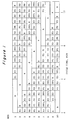
- Figure 1 illustrates an adsorption cycle diagram for a 10 adsorber bed PSA process in accordance with the present invention.
- Figure 2 illustrates an adsorption cycle diagram of a 4 adsorber bed PSA process in accordance with the present invention.
- Figure 3 illustrates the flow connections between the adsorber beds at a particular time during the cycle illustrated in Figure 2.
- the present invention is directed to PSA processes for the separation of a first component from feedstreams comprising said first component and at least one other component.
- first component denotes a non-adsorbed or less strongly adsorbed component in the feedstream.
- other component denotes an adsorbate, i.e., more strongly adsorbed component in the feedstream.
- Suitable feedstreams are those which are gaseous at the adsorption conditions.
- suitable feedstreams are those which contain a hydrogen concentration preferably in the range of from 10 to 90 mol.%.
- Adsorbates, i.e., other components which are present in the feedstream typically include one or more of the following, for example, light hydrocarbons such as methane and ethane, carbon monoxide, carbon dioxide, water, hydrogen sulfide, ammonia, nitrogen and oxygen.
- the feedstream may occasionally comprise other adsorbates such as hydrocarbons in the C3-C6 carbon range, alcohols, ethers, amines, mercaptans, aldehydes, keytones and the like.
- the first component will be determined based upon the other components present in the feed, the adsorption conditions and the adsorbent employed. Thus, there can be instances when the above-described adsorbates can be characterized as the first component. For example, in the separation of nitrogen from methane, nitrogen is the adsorbate and methane is recovered as the non-adsorbed product. In contrast, in hydrogen purification processes, methane is often an adsorbate.
- the processes of the present invention are not limited to particular feedstreams and can be employed to practice a variety of separations such as, for example; the separation of hydrogen from feedstreams comprising hydrogen, methane, carbon monoxide and nitrogen, wherein hydrogen is not adsorbed; the separation of air into nitrogen and oxygen by adsorption of the nitrogen; the separation of carbon dioxide from non-acidic gases such as nitrogen, hydrogen and methane by adsorbing carbon dioxide and the separation of normal butane from isobutane by adsorbing normal butane.
- separations such as, for example; the separation of hydrogen from feedstreams comprising hydrogen, methane, carbon monoxide and nitrogen, wherein hydrogen is not adsorbed; the separation of air into nitrogen and oxygen by adsorption of the nitrogen; the separation of carbon dioxide from non-acidic gases such as nitrogen, hydrogen and methane by adsorbing carbon dioxide and the separation of normal butane from isobutane by adsorbing normal butane.
- Typical feedstreams for processing in accordance with the present invention are derived from refineries, natural gas, air and chemical plants.
- feed sources include reformer off gas from the reforming of light hydrocarbons or methanol, synthesis gas and natural gas.
- a PSA hydrogen process can be operated to provide very high purity hydrogen, e.g., 99+ mol.% for use as a chemical feedstock.
- the process can provide a certain adsorbate concentration in the hydrogen product stream, such as when providing an ammonia synthesis gas having 3 moles of hydrogen per mole of nitrogen, e.g., the product would contain about 75 mol.% hydrogen.
- the isobutane can be used, for example, as alkylate feed or as a gasoline blending component.
- the invention can be carried out using virtually any adsorbent material in the adsorber beds that has capacity for the adsorbate components.
- Suitable adsorbents known in the art and commercially available include crystalline molecular sieves, activated carbons, activated clays, silica gels, activated aluminas and the like.
- the molecular sieves include, for example, the various forms of silicoaluminophosphates and aluminophosphates disclosed in US-A-4,440,871; US-A-4,310,440 and US-A-4,567,027, hereby incorporated by reference as well as zeolitic molecular sieves.
- Zeolitic molecular sieves in the calcined form may be represented by the general formula; Me2O:Al2O3:xSiO2:yH20 where Me is a cation, x has a value from about 2 to infinity, n is the cation valence and y has a value of from about 2 to 10.
- Typical well-known zeolites which may be used include, chabazite, also referred to as Zeolite D, clinoptilolite, erionite, faujasite, also referred to as Zeolite X and Zeolite Y, ferrierite, mordenite, Zeolite A, and Zeolite P.
- Other zeolites suitable for use according to the present invention are those having a high silica content, i.e., those having silica to alumina ratios greater than 10 and typically greater than 100.
- One such high silica zeolite is silicalite, as the term used herein includes both the silicapolymorph of US-A-4,061,724 and also the F-silicate of US-A-4,073,865.
- the PSA cycle of the present invention includes the well known cycle steps of adsorption, one or more equalization steps, countercurrent desorption, purge and repressurization.
- the cycle steps are typically described with reference to their direction relative to the adsorption step.
- cycle steps wherein the gas flow is in a concurrent direction to the adsorption step are known as "cocurrent” steps.
- cycle steps wherein the gas flow is countercurrent to the adsorption step are known as "countercurrent” steps.
- the feedstream is passed to the adsorber bed at an elevated adsorption pressure in order to cause the adsorption of the adsorbate and provide a product stream enriched in the first component relative to feedstream.
- the pressure in the depressurizing bed is released preferably cocurrently and the effluent obtained therefrom, which is preferably rich in the first component, is passed in a countercurrent direction to another adsorber undergoing repressurization.
- a provide-purge-gas step is initiated wherein the adsorber bed is further cocurrently depressurized to provide a purge gas that is relatively impure with respect to the first component and thus is suitable for use as a purge gas.
- a portion of the product gas or gas obtained from one of the equalization steps can be used to supply the purge gas.
- the adsorber bed Upon completion of the provide-purge-gas step, if employed, the adsorber bed is countercurrently depressurized to a desorption pressure in order to desorb the adsorbate. Upon completion of the desorption step the adsorber bed is purged countercurrently with purge gas obtained from another adsorber bed. Finally the adsorber bed is repressurized, first, with equalization gas from other adsorber beds and then with feed or product gas to adsorption pressure. Other additional steps known to those skilled in the art, such as for example, a copurge step wherein the adsorber bed is cocurrently purged at an elevated pressure such as the adsorption pressure with a purge stream comprising the adsorbate, can be employed.
- the present invention is directed to an improvement to the basic PSA cycle sequence described above wherein an additional countercurtent desorption step, i.e., depressurization, is included in the cycle.
- the second countercurrent desorption step is conducted by depressurizing the bed in a countercurrent direction to a second desorption pressure that is lower than the pressure at the end of the first desorption step, i.e., first desorption pressure.
- the countercurtently purging step is performed prior to, or simultaneously with, the second countercurrent desorption step.
- the countercurrently purging step will be completed before the second countercurrent desorption step begins.
- at least a portion of the countercurrently purging step will occur simultaneously with the second countercurrent desorption step. It is of course possible to conduct the countercurrently purging step subsequently to the second countercurrent desorption step.
- the countercurrently purging step is conducted subsequently to the first countercurrent desorption step, this purge helps to sharpen the adsorbate front within the adsorber bed and concentrate the adsorbate at the feed end of the adsorber bed, i.e., where the feedstream is introduced. Accordingly, when the second countercurrent desorption step is then conducted more adsorbate is removed than when no countercurrently purging step is included.
- an effective quantity of purge gas is provided during the countercurrently purging to provide a increased concentration of the adsorbate component in the feed end of the adsorber bed relative to the product end. Even more preferably the effective quantity of purge gas is from 0.5 to 2 volumes of purge gas per volume of feedstream, and even more preferably from 0.5 to 1 volumes of purge gas per volume of feed.
- the pressure reduction during the second countercurrently depressurizing step can be achieved by any means such as a vacuum pump, but preferably in accordance with the present invention the second countercurrently depressurizing step is accomplished with the use of an ejector.
- Suitable ejectors for use in accordance with the present invention are also known in the art as, for example, jet pumps or fluid entrainment pumps, all of which operate according to the following principle: a motive gas stream under an elevated pressure is depressurized through a nozzle where the molecules in the motive gas experience an increase in velocity and thus in momentum. Molecules in the motive gas accelerated in this way then entrain molecules of the medium drawn in as intake by transfer of the momentum within the mixing space.
- the kinetic energy is partially converted back to compression energy in a diffuser so the result is a mixed stream whose pressure is between the original pressure of the motive gas and that of the intake medium.
- the details concerning the design and operation of ejectors is well known to those skilled in the art.
- the motive gas which is used to drive the ejector and create the suction required to achieve the second desorption pressure can be any fluid stream available in the process plant whether it is derived from the PSA process or from another process.
- the motive gas is derived from the PSA process, and even more preferably, comprises the countercurrent desorption effluent from the first desorption step and/or the purge gas feed or effluent from another adsorber bed undergoing said steps simultaneously with the second countercurrent desorption step. This is not to say that the step which supplies the motive gas must be completely simultaneous with the second desorption step, but rather only a portion must be conducted simultaneously.
- motive gas from two or more process steps, or beds can be used to drive the ejector during a single second desorption step.
- motive gas streams that can be used include the feedstream, the adsorption effluent product stream and cocurrent depressurization effluent streams used for equalization.
- a vessel is provided for storing and delivering the ejectors suction benefits at the appropriate time in the PSA cycle.
- the suction side of the ejector is connected to the vessel and thus reduces the pressure therein when the motive gas is available.
- the vessel is connected to said bed undergoing the second stage of desorption to draw it down in pressure causing a rise in pressure in the storage vessel. Still later in the cycle or in a subsequent cycle the ejector again reduces the pressure in the storage vessel.
- the effluent from the ejector i.e., the tail gas
- the effluent from the ejector comprises the desorption effluent streams from the first and second countercurrent desorption effluent streams and will be provided at a tail gas pressure that is sufficient to permit introduction into a fuel gas header.
- Typical fuel gas, and hence tail gas, pressures will be in the range of from 20 to 100 psia (138 to 690 kPa) and preferably from 20 to 50 psia (138 to 345 kPa).
- the temperatures used in the adsorption processs of the present invention are not critical and are dependent on the feedstream and desired separation, although in general the process is substantially isothermal. Typical temperatures range between about -100 to 700° F (-73 to 371 o C), and preferably within the range of 50 to 200° F (10 to 93 o C), and even more preferably from about 50 to 150° F (10 to 66 o C) for hydrogen purification.
- the countercurrently purging step described above is to be performed at about the same temperature as the adsorption step, preferably within 50° F (10 oC) and more preferably within 20° F (-6.7 o C). It is to be understood, however, that even though the process is generally isothermal, there is to be expected a certain degree of temperature increase and decrease associated with the thermal effects of the heats of adsorption and desorption.
- the absolute pressure levels employed during the PSA process are not critical provided that the pressure differential between the adsorption and desorption steps is sufficient to cause a change in the adsorbate fraction loading on the adsorbent thereby providing a delta loading effective for separating the feedstream.
- Typical pressure levels range from 100 to 2000 psia (6980 to 13790 kPa), more preferably from 200 to 1000 psia (1396 to 6895 kPa), and even more preferably from 400 to 1000 psia (2758 to 6895 kPa), during the adsorption step; and from 1 to 500 psia (6.9 to 3448 kPa), more about 5 to 50 psia (34 to 345 kPa), at the end of the second desorption step.
- the pressures during the equalization steps provide purge step first countercurrent desorption step and countercurrent purge step are intermediate between the adsorption and second desorption steps.
- the pressure at the end of the first desorption step is above atmospheric pressure.
- the second desorption pressure be selected in combination with the first desorption pressure to provide the desired tail gas pressure.
- the second desorption pressure can either bed above or below atmospheric pressure. For example, if the first desorption step is initiated at a relatively high pressure and the first desorption effluent is used as motive gas in the ejector, then it will be possible to obtain a lower pressure at the end of the second desorption step and still provide a tail gas pressure intermediate between the starting motive gas pressure and the ending second desorption pressure, and still sufficiently high to be passed through a fuel gas header.
- the total cycle time that is, the time required to perform all the individual steps in the PSA cycle ranges from 3 to 30 minutes, and more preferably within the range of 4 to 20 minutes.
- At least two adsorber beds are required in order to perform each equalization step and typically at least four adsorber beds are required in order to provide a constant source of product gas.
- Preferably from about 4 to 14 adsorber beds are employed, more preferably from about 7 to 14, and most preferably from about 10 to 12 in accordance with the present invention.
- a PSA process having 10 adsorber beds with three adsorbers on an adsorption step at any given time, and three equalization steps was simulated using a computer simulation model routinely used for designing commercial PSA processes.
- the basis for the simulation was that the above-described PSA process would be capable of treating 60 MMSCFD (1.7 x10⁶m3) of a feedstream at 600 psia (4137 kPa) having a composition of 20 mole % methane with the balance hydrogen.
- the cycle comprised the steps of adsorption at 600 psia (4137 kPa), three equalization steps, and a provide-purge-gas step with the pressure at the end of the provide-purge-gas step at 145 psia (1000 kPa), followed by a countercurrent desorption step to a pressure of 25 psia (172 kPa), a countercurrently purging step with a purge quantity of about 0.6 volumes of purge gas per volume of feed, followed by a repressurization with equalization gas and product gas.
- a second simulation was performed on a cycle similar to that described above with the exception that no provide-purge-gas or countercurrently purging steps were included.
- the process was simulated to provide a pressure at the end of the first desorption step of 25 psia (172 kPa).
- a second desorption step was included whereby an ejector was employed to reduce the pressure during the second desorption step to 11 psia (76 kPa).
- the motive gas used to drive the ejector was obtained from another adsorber bed undergoing the first desorption step.
- the ejector performance was simulated based on conventional single stage ejector performance charts for a throat to nozzle area ratio of 10 with an additional 25% contingency to account for the non-steady state operation and non-optimum area ratios at the beginning and the end of the first countercurrent desorption step.
- FIG. 1 illustrates a 10 bed PSA cycle that employes the process of the present invention wherein two countercurrent desorption steps are provided in conjunction with a countercurrently purging step.
- the cycle sequence is similar to that described to Examples 1 and 2.
- bed (1) first undergoes an adsorption step which is then followed by three equalization steps, wherein the effluent obtained therefrom is passed to adsorber beds 5, 6 and 7 respectively, each of which are labeled E1, E2 and E3 during the appropriate time frame.
- Bed (1) then undergoes a series of provide purge steps labeled PP1, H and PP2, which are analogous to a single provide-purge-gas step in the cycle described in Example 1.
- the effluent obtained is passed to bed 9, undergoing a first purging step.
- the time period labeled H represents a hold period wherein the bed is isolated.
- the effluent obtained therefrom is passed to bed 9 during the time frame labeled PR.
- the valves on the feed end of bed 9 are closed in order to begin the repressurization sequence.
- a valve on the feed end of bed 9 could left open in order to provide a second purge step during this time frame.
- the decision to purge or repressurize during the second provide purge step is not critical to the present invention and can be made by one skilled in the art.
- adsorber bed (1) is depressurized countercurrently during the time period labeled D1 to a pressure of 25 psia (172 kPa).
- adsorber bed (1) is purged countercurrently during the time period labeled P1 with provide purge gas obtained from adsorber bed (3) undergoing the first provide-purge-gas step.
- bed (1) is further countercurrently depressurized to about 11 psia (76 kPa). This second pressure reduction is accomplished by the use of an ejector which is operative communication with adsorber bed (2) undergoing the first depressurization stage.
- adsorber bed (1) is repressurized during the time periods PR, E3, E2, E1 and R with effluent gas obtained from adsorber beds (3), (5), (6), (7) and the effluent product gas from at least one of adsorber beds (8), (9) or (10).
- adsorber bed (1) could alternately be purged a second time.
- the time period corresponding to P1, D2 and PR, in Figure 1, is analogous to the time period wherein the adsorber bed is purged in Example 1.
- FIG. 2 illustrates an adsorption cycle diagram for a PSA process in accordance with the present invention having four adsorber beds.
- the second countercurrent desorption step is conducted simultaneously with the countercurrent purge step.
- the adsorber bed that is undergoing the first countercurrent desorption step which preferably provides the motive gas to drive an ejector, is simultaneously cocurrently depressurized to provide purge gas.
- This type of step is known in the PSA art as a dual-ended depressurization.
- the cycle comprises an adsorption step labeled A, followed by an equalization step during time period E1, wherein the effluent gas is passed to adsorber bed (3) undergoing equalization.
- the bed is depressurized both cocurrently and countercurrently to provide the purge gas and the first desorption effluent gas.
- the bed is further countercurrently depressurized and simultaneously countercurrently purged during the time period labeled D2/P.
- the adsorber bed is repressurized during the E1 and R time periods.
- FIG 3 illustrates the flow connections between adsorber beds at a time period during the adsorption cycle shown in Figure 2 at about 3 minutes. It can be seen that bed (1) is undergoing the adsorption step wherein a feedstream is passed to the feed end of the adsorber bed and an effluent stream is withdrawn from the product end of the adsorber bed. A portion of the effluent stream is withdrawn as product and the remaining portion is passed to adsorber bed (2) undergoing repressurization. Adsorber bed (3) is simultaneously being countercurrently purged and countercurrently depressurized to the second desorption pressure. The pressure reduction is accomplished by passing the second desorption effluent stream labeled "D2 gas" to the suction side of an ejector.
- D2 gas the second desorption effluent stream labeled "D2 gas"
- Purge gas obtained from the product end of bed (4) is used to countercurrently purge adsorber bed (3).
- Adsorber bed (4) is undergoing a dual ended depressurization step in order to provide purge gas for purging adsorber bed (3) and the first desorption effluent gas labeled "D1 gas" which is used as a motive gas to drive the ejector.
- a tail gas stream comprising the first and second desorption effluent streams is withdrawn from the ejector and removed from the process.
- the feedstream can be used as a motive gas to drive the ejector which is in operative communication with a bed undergoing the countercurrent desorption step.
- the effluent from the ejector can be returned to the feed side of another adsorber bed as copurge gas.
- more than two countercurrent desorption steps can be employed within the process of the present invention. In such cases it is preferred to perform the countercurrent purge step prior to the final countercurrent desorption step. It is to be further noted that all references to patents and publicationS not specifically incorporated by reference are hereby incorporated by reference herein.
Landscapes
- Chemical & Material Sciences (AREA)
- Engineering & Computer Science (AREA)
- Analytical Chemistry (AREA)
- General Chemical & Material Sciences (AREA)
- Oil, Petroleum & Natural Gas (AREA)
- Chemical Kinetics & Catalysis (AREA)
- Separation Of Gases By Adsorption (AREA)
Abstract
A pressure swing adsorption (PSA) process for purifying or separating gases employs, in addition to a standard PSA cycle comprising an adsorption step (a), one or more cocurrent depressurization steps (b) for equalization or providing purge gas, a countercurrent depressurization step (c), a countercurrent purge step (d), and a repressurization step (f), an additional countercurrent desorption step (e) performed in conjunction with the first countercurrent desorption step at above atmospheric pressure and a countercurrent purge step at about the adsorption temperature which can provide increased capacity and recovery as compared to PSA processes that only have one countercurrent depressurization step or otherwise do not have a countercurrent purge step. Preferably the pressure reduction during the second countercurrent depressurization step is accomplished by passing another stream from the process, such as the effluent from the first countercurrent desorption step, as a motive gas through an ejector which is in operative communication with the adsorber bed undergoing the second countercurrent desorption step.
Description
- The present invention generally relates to pressure swing adsorption (PSA) processes and more particularly to improved PSA processes for the separation or purification of gases wherein multiple countercurrent depressurization steps are employed in conjunction with a countercurrent purge step.
- PSA processes provide an efficient and economical means for separating a multi-component gas stream containing at least two gases having different adsorption characteristics. The more strongly adsorbed gas can be an impurity which is removed from the less strongly adsorbed gas which is taken off as product, or, the more strongly adsorbed gas can be the desired product which is separated from the less strongly adsorbed gas. For example, carbon monoxide and light hydrocarbons can be removed from a hydrogen-containing feedstream to produce a purified (99+ %) hydrogen stream for a hydrocracking or other catalytic process where these impurities could adversely affect the catalyst or the reaction. Similarly, more strongly adsorbed gases, such as ethylene, can be recovered from a feedstream to produce an ethylene-rich product.
- In PSA processes, a multi component gas is typically passed to at least one of a plurality of adsorption zones at an elevated pressure effective to adsorb at least one component, i.e. the more strongly adsorbed components, while at least one other component passes through, i.e. the less strongly adsorbed components. At a defined time, the passing of feedstream to the adsorber is terminated and the adsorption zone is depressurized by one or more cocurrent depressurization steps wherein the pressure is reduced to a defined level which permits the separated, less strongly adsorbed component or components remaining in the adsorption zone to be drawn off without significant concentration of the more strongly adsorbed components. Then, the adsorption zone is depressurized by a countercurrent depressurization step wherein the pressure in the adsorption zone is further reduced by withdrawing desorbed gas countercurrently to the direction of the feedstream. Finally, the adsorption zone is purged and repressurized. Such PSA processing is disclosed in US-A-3,430,418; US-A-3,564,816 and in US-A-3,986,849 and described in these patents, the contents of which are incorporated herein by reference, the PSA process is generally carried out in a sequential processing cycle that includes each bed of the PSA system.
- The more strongly adsorbed components, i.e., the adsorbate, are removed from the adsorber bed by countercurrently depressurizing the adsorber bed to a desorption pressure. Lower desorption pressures are preferred in order to provide more complete removal of the adsorbate during the desorption step. Lower desorption pressures can also provide a greater capacity differential between adsorption and desorption conditions and thus increase the capacity of the process. However, very low desorption pressures, i.e., below atmospheric pressure, are not often used because of the technical complexities and cost associated therewith, e.g., vacuum pumping and the like. Additionally, in hydrogen purification it is often necessary to provide the desorption effluent stream, also known as tail gas, at a pressure suitable for feeding into a fuel gas header, e.g., 20-100 psia (138 to 690 kPa). Accordingly, when vacuum pumps are employed in PSA processes, the discharge pressure is typically maintained at or higher than the fuel gas pressure. When vacuum pumps are not employed, PSA hydrogen processes typically employ a desorption pressure of greater than or equal to the fuel gas pressure.
- EP-B-15413 discloses a pressure swing adsorption process which employes a two stage countercurtent desorption step for the removal of adsorbed components which can achieve sub-atmospheric pressure. The patent discloses that the desorption pressures are produced with the aid of jet devices, i.e., ejectors, and that gas or gas mixtures which have pressures higher than the desorption pressure and which are formed in the course of the process are used as drive means, i.e., motive gas, for the jet devices. Examples of the drive means include: the adsorption effluent, the feedstream and the effluent from the first countercurrent desorption step.
- US-A-4,813,980 discloses a multi-column pressure swing adsorption process for simultaneous production of ammonia synthesis gas and carbon dioxide from a reformer off gas having hydrogen, nitrogen and carbon dioxide as major components accompanied by minor quantities of methane, carbon monoxide and argon as impurities. The PSA system features two groups of adsorber beds in which CO₂ is adsorbed in the adsorbers of the first group, i.e., the A beds, the essentially CO₂-free effluent being charged to an adsorber of the second group, i.e., the B beds, for removal of minor impurities while discharging an effluent gas having an H₂/N₂ content stoichiometric for NH₃ synthesis. The CO₂ recovered from the first group of adsorbers is available at a high purity for reaction with the ammonia product for production of urea. The first group of adsorber beds employ a two-stage countercurrent desorption step wherein during the first stage the adsorber bed is depressurized by the discharge of the contained gas to near ambient pressure. During the second desorption step the adsorber bed evacuated to sub-atmospheric level with further removal of the CO₂ rich effluent.
- One problem with the two stage desorption steps of the prior art is that no provision is made for a countercurrent purge step to be used in conjunction with the two desorption steps. Thus, the two countercurtent desorption steps are functionally similar to one continuous countercurtent desorption step. Countercurrent purge steps are often employed in PSA processes to further desorb adsorbate from the adsorber bed and additionally remove adsorbate remaining in the void spaces of the adsorber bed after the countercurrent desorption step. PSA adsorption cycles that employ a countercurrent desorption step with a countercurrent purge step typically provide enhanced purity, capacity and recovery as compared to PSA adsorption cycles that do not employ a countercurrent purge step. US-A-3,430,418 and US-A-3,986,849, for example, disclose the use of countercurrent purge steps in PSA adsorption cycles. In fact, US-A-4,813,980, which discloses two countercurrent desorption steps in the A beds, also discloses the use of a countercurrent purge step but only in conjunction with the single stage countercurrent desorption step in the B beds.
- Thus, improved PSA processes are sought which employ multiple desorption steps in addition to a countercurrent purge step wherein the first countercurrent depressurization step can be conducted at above-atmospheric pressure. Improved processes are further sought wherein the countercurrent purge step is conducted at or near the adsorption temperature and further that the tail gas obtained from the process be available at a tail gas pressure that is sufficient for use as a fuel gas.
- By the present invention PSA processes suitable for separating or purifying feedstreams are provided which employ multiple countercurrent desorption steps in addition to a countercurrent purge step. The processes can provide enhanced recovery of the non-adsorbed components and capacity for the adsorbate components. Preferably two countercurrent desorption steps are employed with a countercurrent purge step between the two desorption steps. The first countercurrent desorption step is conducted at above atmospheric pressure and at about the temperature at which the adsorption step is conducted. It is further preferred that the desorption effluent stream from the first desorption step is used as a motive gas to drive an ejector in operative communication with another adsorber bed undergoing the second desorption step in order to provide a tail gas stream at a tail gas pressure that is intermediate between the first and second desorption pressures.
- In one aspect of the present invention there is provided a PSA process for separating a first component from a feedstream comprising said first component and at least one other component, wherein a plurality of adsorber beds are employed and each of said adsorber beds is subjected to a repetitive cycle comprising the steps of: (a) passing the feedstream to a first adsorber bed containing adsorbent having adsorptive capacity for the other component at effective adsorption conditions including an adsorption pressure and temperature, and withdrawing a product stream enriched in said first component relative to the feedstream from the first adsorber bed; (b) cocurrently depressurizing the first adsorber bed to an equalization pressure that is lower than the adsorption pressure and passing the effluent therefrom to a second adsorber bed being repressurized; (c) countercurrently depressurizing the first adsorber bed to a first desorption pressure that is above atmospheric pressure and lower than the equalization pressure and effective to desorb the other component and withdrawing a first desorption effluent comprising said other component; (d) countercurrently purging the first adsorber bed with a purge feed comprising the first component at about the adsorption temperature and withdrawing a purge effluent comprising the other component; (e) either simultaneously with or subsequently to step (d) further countercurrently depressurizing the first adsorber bed to a second desorption pressure that is lower than the first desorption pressure and effective to further desorb the other component and withdrawing a second desorption effluent stream comprising said other component; and (f) repressurizing the first adsorber bed to the adsorption pressure.
- In another aspect of the present invention there is provided a PSA process for separating a first component from a feedstream comprising said first component and at least one other component, wherein a plurality of adsorber beds having a feed end and a product end are employed and each of said adsorber beds is subjected to a repetitive cycle comprising the steps of: (a) passing the feedstream to the feed end of a first adsorber bed containing adsorbent having adsorptive capacity for the other component at effective adsorption conditions including an adsorption pressure and temperature, and withdrawing a product stream enriched in the first component, relative to the feedstream, from the product end of the first adsorber bed; (b) cocurrently depressurizing the first adsorber bed to an equalization pressure that is lower than the adsorption pressure and passing the effluent therefrom to the product end of a second adsorber bed being repressurized; (c) countercurrently depressurizing the first adsorber bed to a first desorption pressure that is above atmospheric pressure and lower than the equalization pressure and effective to desorb the other component and withdrawing a first desorption effluent comprising the other component from the feed end of the first adsorber bed; (d) countercurrently purging the first adsorber bed with a purge feed comprising the first component at about the adsorption temperature and withdrawing a purge effluent comprising the other component from the feed end of the first adsorber bed; (e) either simultaneously with or subsequently to the countercurrently purging, further countercurrently depressurizing the first adsorber bed to a second desorption pressure that is lower than the first desorption pressure and effective to further desorb the other component and withdrawing a second desorption effluent stream comprising the other component from the feed end of the first adsorber bed, wherein the further countercurrently depressurizing is conducted by passing at least a portion of the first desorption effluent stream from a third adsorber bed which is simultaneously undergoing the countercurrently depressurizing to the first desorption pressure, through an ejector in operative communication with the first adsorber bed; and (f) repressurizing the first adsorber bed to the adsorption pressure.
- Figure 1 illustrates an adsorption cycle diagram for a 10 adsorber bed PSA process in accordance with the present invention.
- Figure 2 illustrates an adsorption cycle diagram of a 4 adsorber bed PSA process in accordance with the present invention.
- Figure 3 illustrates the flow connections between the adsorber beds at a particular time during the cycle illustrated in Figure 2.
- The present invention is directed to PSA processes for the separation of a first component from feedstreams comprising said first component and at least one other component. In accordance with the present invention, the term "first component" denotes a non-adsorbed or less strongly adsorbed component in the feedstream. The term "other component" denotes an adsorbate, i.e., more strongly adsorbed component in the feedstream.
- The processes can be used to perform bulk separations or purification separations and accordingly have applicability to a wide variety of feedstreams. Suitable feedstreams are those which are gaseous at the adsorption conditions. When the invention is applied to separation or purification of hydrogen-containing feedstreams, suitable feedstreams are those which contain a hydrogen concentration preferably in the range of from 10 to 90 mol.%. Adsorbates, i.e., other components which are present in the feedstream typically include one or more of the following, for example, light hydrocarbons such as methane and ethane, carbon monoxide, carbon dioxide, water, hydrogen sulfide, ammonia, nitrogen and oxygen. The feedstream may occasionally comprise other adsorbates such as hydrocarbons in the C₃-C₆ carbon range, alcohols, ethers, amines, mercaptans, aldehydes, keytones and the like. The first component will be determined based upon the other components present in the feed, the adsorption conditions and the adsorbent employed. Thus, there can be instances when the above-described adsorbates can be characterized as the first component. For example, in the separation of nitrogen from methane, nitrogen is the adsorbate and methane is recovered as the non-adsorbed product. In contrast, in hydrogen purification processes, methane is often an adsorbate.
- Thus, the processes of the present invention are not limited to particular feedstreams and can be employed to practice a variety of separations such as, for example; the separation of hydrogen from feedstreams comprising hydrogen, methane, carbon monoxide and nitrogen, wherein hydrogen is not adsorbed; the separation of air into nitrogen and oxygen by adsorption of the nitrogen; the separation of carbon dioxide from non-acidic gases such as nitrogen, hydrogen and methane by adsorbing carbon dioxide and the separation of normal butane from isobutane by adsorbing normal butane.
- Typical feedstreams for processing in accordance with the present invention are derived from refineries, natural gas, air and chemical plants. Examples of feed sources include reformer off gas from the reforming of light hydrocarbons or methanol, synthesis gas and natural gas.
- The products obtained in the process of the present invention accordingly have a variety of uses depending upon the feedstream. For example, a PSA hydrogen process can be operated to provide very high purity hydrogen, e.g., 99⁺ mol.% for use as a chemical feedstock. Alternately, the process can provide a certain adsorbate concentration in the hydrogen product stream, such as when providing an ammonia synthesis gas having 3 moles of hydrogen per mole of nitrogen, e.g., the product would contain about 75 mol.% hydrogen. When butane feedstreams are separated to form an isobutane product, the isobutane can be used, for example, as alkylate feed or as a gasoline blending component.
- The invention can be carried out using virtually any adsorbent material in the adsorber beds that has capacity for the adsorbate components. Suitable adsorbents known in the art and commercially available include crystalline molecular sieves, activated carbons, activated clays, silica gels, activated aluminas and the like. The molecular sieves include, for example, the various forms of silicoaluminophosphates and aluminophosphates disclosed in US-A-4,440,871; US-A-4,310,440 and US-A-4,567,027, hereby incorporated by reference as well as zeolitic molecular sieves.
- Zeolitic molecular sieves in the calcined form may be represented by the general formula;
Me₂O:Al₂O₃:xSiO₂:yH₂0
where Me is a cation, x has a value from about 2 to infinity, n is the cation valence and y has a value of from about 2 to 10. - Typical well-known zeolites which may be used include, chabazite, also referred to as Zeolite D, clinoptilolite, erionite, faujasite, also referred to as Zeolite X and Zeolite Y, ferrierite, mordenite, Zeolite A, and Zeolite P. Other zeolites suitable for use according to the present invention are those having a high silica content, i.e., those having silica to alumina ratios greater than 10 and typically greater than 100. One such high silica zeolite is silicalite, as the term used herein includes both the silicapolymorph of US-A-4,061,724 and also the F-silicate of US-A-4,073,865.
- The PSA cycle of the present invention includes the well known cycle steps of adsorption, one or more equalization steps, countercurrent desorption, purge and repressurization. The cycle steps are typically described with reference to their direction relative to the adsorption step. Thus cycle steps wherein the gas flow is in a concurrent direction to the adsorption step are known as "cocurrent" steps. Similarly cycle steps wherein the gas flow is countercurrent to the adsorption step are known as "countercurrent" steps. During the adsorption step the feedstream is passed to the adsorber bed at an elevated adsorption pressure in order to cause the adsorption of the adsorbate and provide a product stream enriched in the first component relative to feedstream. During the equalization steps the pressure in the depressurizing bed is released preferably cocurrently and the effluent obtained therefrom, which is preferably rich in the first component, is passed in a countercurrent direction to another adsorber undergoing repressurization. Typically at the conclusion of the equalization step a provide-purge-gas step is initiated wherein the adsorber bed is further cocurrently depressurized to provide a purge gas that is relatively impure with respect to the first component and thus is suitable for use as a purge gas. Optionally instead of the provide-purge-gas step a portion of the product gas or gas obtained from one of the equalization steps can be used to supply the purge gas. Upon completion of the provide-purge-gas step, if employed, the adsorber bed is countercurrently depressurized to a desorption pressure in order to desorb the adsorbate. Upon completion of the desorption step the adsorber bed is purged countercurrently with purge gas obtained from another adsorber bed. Finally the adsorber bed is repressurized, first, with equalization gas from other adsorber beds and then with feed or product gas to adsorption pressure. Other additional steps known to those skilled in the art, such as for example, a copurge step wherein the adsorber bed is cocurrently purged at an elevated pressure such as the adsorption pressure with a purge stream comprising the adsorbate, can be employed.
- The present invention is directed to an improvement to the basic PSA cycle sequence described above wherein an additional countercurtent desorption step, i.e., depressurization, is included in the cycle. The second countercurrent desorption step is conducted by depressurizing the bed in a countercurrent direction to a second desorption pressure that is lower than the pressure at the end of the first desorption step, i.e., first desorption pressure.
- In order to achieve the benefits of the present invention it is necessary to include a countercurrent purge step in conjunction with the two countercurrent desorption steps. Preferably the countercurtently purging step is performed prior to, or simultaneously with, the second countercurrent desorption step. Thus, in some instances, the countercurrently purging step will be completed before the second countercurrent desorption step begins. In other instances at least a portion of the countercurrently purging step will occur simultaneously with the second countercurrent desorption step. It is of course possible to conduct the countercurrently purging step subsequently to the second countercurrent desorption step. Without being limited to any particular theory, it is believed that if the countercurrently purging step is conducted subsequently to the first countercurrent desorption step, this purge helps to sharpen the adsorbate front within the adsorber bed and concentrate the adsorbate at the feed end of the adsorber bed, i.e., where the feedstream is introduced. Accordingly, when the second countercurrent desorption step is then conducted more adsorbate is removed than when no countercurrently purging step is included. Preferably, an effective quantity of purge gas is provided during the countercurrently purging to provide a increased concentration of the adsorbate component in the feed end of the adsorber bed relative to the product end. Even more preferably the effective quantity of purge gas is from 0.5 to 2 volumes of purge gas per volume of feedstream, and even more preferably from 0.5 to 1 volumes of purge gas per volume of feed.
- The pressure reduction during the second countercurrently depressurizing step can be achieved by any means such as a vacuum pump, but preferably in accordance with the present invention the second countercurrently depressurizing step is accomplished with the use of an ejector. Suitable ejectors for use in accordance with the present invention are also known in the art as, for example, jet pumps or fluid entrainment pumps, all of which operate according to the following principle: a motive gas stream under an elevated pressure is depressurized through a nozzle where the molecules in the motive gas experience an increase in velocity and thus in momentum. Molecules in the motive gas accelerated in this way then entrain molecules of the medium drawn in as intake by transfer of the momentum within the mixing space. The kinetic energy is partially converted back to compression energy in a diffuser so the result is a mixed stream whose pressure is between the original pressure of the motive gas and that of the intake medium. The details concerning the design and operation of ejectors is well known to those skilled in the art.
- In aspects of the invention wherein an ejector is employed, the motive gas which is used to drive the ejector and create the suction required to achieve the second desorption pressure can be any fluid stream available in the process plant whether it is derived from the PSA process or from another process. Preferably however, the motive gas is derived from the PSA process, and even more preferably, comprises the countercurrent desorption effluent from the first desorption step and/or the purge gas feed or effluent from another adsorber bed undergoing said steps simultaneously with the second countercurrent desorption step. This is not to say that the step which supplies the motive gas must be completely simultaneous with the second desorption step, but rather only a portion must be conducted simultaneously. In fact, motive gas from two or more process steps, or beds, can be used to drive the ejector during a single second desorption step. Examples of other motive gas streams that can be used include the feedstream, the adsorption effluent product stream and cocurrent depressurization effluent streams used for equalization.
- Those skilled in the art will recognize that many of the preferred motive gases used in accordance with the present invention undergo unsteady flow conditions due to the decreasing pressure and hence flow rate of the depressurizing adsorber bed. Thus, under such conditions many ejectors will not perform as well as a conventional design chart would indicate wherein the motive gas is provided at a steady pressure and flow rate. Accordingly, it may be desirable to install two or more ejectors each being optimized for the particular flow condition that it will expenence. For example, at the beginning of the first countercurrent depressurization step when the pressure and flow rate of the motive gas are high, it would be preferred to employ a higher throat to nozzle area ratio than an ejector used on the motive gas at the end of the countercurrent desorption step, i.e., low pressure and low flow rate. Alternatively, it may be desirable to provide an ejector with a variable throat to nozzle area ratio in order to accommodate the varying motive gas conditions.
- Further, in accordance with the present invention it is not necessary for an ejector to be connected directly with its suction side to the adsorber simultaneously undergoing the second stage of desorption. Instead, in one aspect of the invention, a vessel is provided for storing and delivering the ejectors suction benefits at the appropriate time in the PSA cycle. As such the suction side of the ejector is connected to the vessel and thus reduces the pressure therein when the motive gas is available. Later in the cycle when it is necessary to employ the suction benefits of the ejector to reduce the pressure in an adsorber bed, the vessel is connected to said bed undergoing the second stage of desorption to draw it down in pressure causing a rise in pressure in the storage vessel. Still later in the cycle or in a subsequent cycle the ejector again reduces the pressure in the storage vessel.
- When the process of the present invention is used for hydrogen purification, it is preferred that the effluent from the ejector, i.e., the tail gas, comprises the desorption effluent streams from the first and second countercurrent desorption effluent streams and will be provided at a tail gas pressure that is sufficient to permit introduction into a fuel gas header. Typical fuel gas, and hence tail gas, pressures will be in the range of from 20 to 100 psia (138 to 690 kPa) and preferably from 20 to 50 psia (138 to 345 kPa).
- The temperatures used in the adsorption processs of the present invention are not critical and are dependent on the feedstream and desired separation, although in general the process is substantially isothermal. Typical temperatures range between about -100 to 700° F (-73 to 371oC), and preferably within the range of 50 to 200° F (10 to 93oC), and even more preferably from about 50 to 150° F (10 to 66oC) for hydrogen purification. In accordance with the present invention the countercurrently purging step described above is to be performed at about the same temperature as the adsorption step, preferably within 50° F (10oC) and more preferably within 20° F (-6.7oC). It is to be understood, however, that even though the process is generally isothermal, there is to be expected a certain degree of temperature increase and decrease associated with the thermal effects of the heats of adsorption and desorption.
- Similarly the absolute pressure levels employed during the PSA process are not critical provided that the pressure differential between the adsorption and desorption steps is sufficient to cause a change in the adsorbate fraction loading on the adsorbent thereby providing a delta loading effective for separating the feedstream. Typical pressure levels range from 100 to 2000 psia (6980 to 13790 kPa), more preferably from 200 to 1000 psia (1396 to 6895 kPa), and even more preferably from 400 to 1000 psia (2758 to 6895 kPa), during the adsorption step; and from 1 to 500 psia (6.9 to 3448 kPa), more about 5 to 50 psia (34 to 345 kPa), at the end of the second desorption step. It is to be understood that the pressures during the equalization steps provide purge step first countercurrent desorption step and countercurrent purge step are intermediate between the adsorption and second desorption steps. In accordance with
the present invention, the pressure at the end of the first desorption step is above atmospheric pressure. - In some instances such as in hydrogen purification, it is preferred that the second desorption pressure be selected in combination with the first desorption pressure to provide the desired tail gas pressure. Thus the second desorption pressure can either bed above or below atmospheric pressure. For example, if the first desorption step is initiated at a relatively high pressure and the first desorption effluent is used as motive gas in the ejector, then it will be possible to obtain a lower pressure at the end of the second desorption step and still provide a tail gas pressure intermediate between the starting motive gas pressure and the ending second desorption pressure, and still sufficiently high to be passed through a fuel gas header.
- In general the total cycle time, that is, the time required to perform all the individual steps in the PSA cycle ranges from 3 to 30 minutes, and more preferably within the range of 4 to 20 minutes. At least two adsorber beds are required in order to perform each equalization step and typically at least four adsorber beds are required in order to provide a constant source of product gas. Preferably from about 4 to 14 adsorber beds are employed, more preferably from about 7 to 14, and most preferably from about 10 to 12 in accordance with the present invention.
- A PSA process having 10 adsorber beds with three adsorbers on an adsorption step at any given time, and three equalization steps was simulated using a computer simulation model routinely used for designing commercial PSA processes. The basis for the simulation was that the above-described PSA process would be capable of treating 60 MMSCFD (1.7 x10⁶m³) of a feedstream at 600 psia (4137 kPa) having a composition of 20 mole % methane with the balance hydrogen. The cycle comprised the steps of adsorption at 600 psia (4137 kPa), three equalization steps, and a provide-purge-gas step with the pressure at the end of the provide-purge-gas step at 145 psia (1000 kPa), followed by a countercurrent desorption step to a pressure of 25 psia (172 kPa), a countercurrently purging step with a purge quantity of about 0.6 volumes of purge gas per volume of feed, followed by a repressurization with equalization gas and product gas.
- The results of this simulation are shown in Table 1 under the first column entitled "Single Stage Desorption".

- It can be seen that the above-described cycle produced a capacity of 82.5, hydrogen recovery of 84.4%, and productivity of 69.5%.
- A second simulation was performed on a cycle similar to that described above with the exception that no provide-purge-gas or countercurrently purging steps were included. The process was simulated to provide a pressure at the end of the first desorption step of 25 psia (172 kPa). In addition a second desorption step was included whereby an ejector was employed to reduce the pressure during the second desorption step to 11 psia (76 kPa). The motive gas used to drive the ejector was obtained from another adsorber bed undergoing the first desorption step. The ejector performance was simulated based on conventional single stage ejector performance charts for a throat to nozzle area ratio of 10 with an additional 25% contingency to account for the non-steady state operation and non-optimum area ratios at the beginning and the end of the first countercurrent desorption step. The simulation indicated that the adsorber bed undergoing the second desorption step could be drawn down to 8 psia (55 kPa), however in order to account for resistances due to pressure drop, 3 psi (21 kPa) were added to arrive at final desorption pressure, 11 psia (76 kPa).
- In can be seen from Table 1, second column, entitled "Dual Stage Desorption - without purge", that the capacity factor was increased to 87.4, with the addition of the second desorption step. Also the recovery was improved by 1% to 85.4%, and the productivity was increased to 74.6%. Much of this improvement resulted from increasing the pressure swing of the overall cycle from the highest pressure of the feed to the lowest pressure of the last desorption step. This new cycle permitted the waste pressure to be reduced to 11 psia (76 kPa), a level which could not be reached in the cycle of Example 1 without this second desorption step.
- Figure 1 illustrates a 10 bed PSA cycle that employes the process of the present invention wherein two countercurrent desorption steps are provided in conjunction with a countercurrently purging step. The cycle sequence is similar to that described to Examples 1 and 2. For instance, following the cycle's progression of bed (1) it can be seen that bed (1) first undergoes an adsorption step which is then followed by three equalization steps, wherein the effluent obtained therefrom is passed to adsorber
beds bed 9, undergoing a first purging step. The time period labeled H, represents a hold period wherein the bed is isolated. During the second provide-purge-gas step, labeled PP2, the effluent obtained therefrom is passed tobed 9 during the time frame labeled PR. During this time period the valves on the feed end ofbed 9 are closed in order to begin the repressurization sequence. Alternately, a valve on the feed end ofbed 9 could left open in order to provide a second purge step during this time frame. The decision to purge or repressurize during the second provide purge step is not critical to the present invention and can be made by one skilled in the art. After the second provide purge step, adsorber bed (1) is depressurized countercurrently during the time period labeled D1 to a pressure of 25 psia (172 kPa). At this point in accordance with the present invention adsorber bed (1) is purged countercurrently during the time period labeled P1 with provide purge gas obtained from adsorber bed (3) undergoing the first provide-purge-gas step. At the conclusion of the countercurrently purging, bed (1) is further countercurrently depressurized to about 11 psia (76 kPa). This second pressure reduction is accomplished by the use of an ejector which is operative communication with adsorber bed (2) undergoing the first depressurization stage. After the second desorption stage is completed adsorber bed (1) is repressurized during the time periods PR, E3, E2, E1 and R with effluent gas obtained from adsorber beds (3), (5), (6), (7) and the effluent product gas from at least one of adsorber beds (8), (9) or (10). As previously noted with respect to adsorber bed (9) during the time period labeled PR, adsorber bed (1) could alternately be purged a second time. The time period corresponding to P1, D2 and PR, in Figure 1, is analogous to the time period wherein the adsorber bed is purged in Example 1. - The results from the simulation of the process in accordance with the present invention are shown in Table 1,
column 3, titled "Dual Stage Desorption - with purge." It can be seen that the performance of the process is substantially improved by the addition of the countercurrent purge in addition to the second desorption step. Note, for example, that the capacity factor was increased to 91.5, the hydrogen recovery was increased to 87.0, and the productivity was increased to 79.6%. Although not shown in the Table, even when a substantial purge quantity was employed, e.g., 1.4 volumes of purge per volume of feed, the performance of the cycle simulated in Example 3 was improved compared to the performance obtained with the cycle simulated in Example 1. As in Example 3, the improved cycle increased the pressure swing of the overall cycle to reach a lower waste gas pressure of 11 psia (76 Kpa) to provide the productivity benefits. - Figure 2 illustrates an adsorption cycle diagram for a PSA process in accordance with the present invention having four adsorber beds. In this aspect of the present invention the second countercurrent desorption step is conducted simultaneously with the countercurrent purge step. Additionally, the adsorber bed that is undergoing the first countercurrent desorption step, which preferably provides the motive gas to drive an ejector, is simultaneously cocurrently depressurized to provide purge gas. This type of step is known in the PSA art as a dual-ended depressurization. Referring to bed (1) in Figure 2, the cycle comprises an adsorption step labeled A, followed by an equalization step during time period E1, wherein the effluent gas is passed to adsorber bed (3) undergoing equalization. The bed is depressurized both cocurrently and countercurrently to provide the purge gas and the first desorption effluent gas. At the conclusion of the first desorption/provide purge step the bed is further countercurrently depressurized and simultaneously countercurrently purged during the time period labeled D2/P. At the conclusion of the second desorption/purging step the adsorber bed is repressurized during the E1 and R time periods.
- Figure 3 illustrates the flow connections between adsorber beds at a time period during the adsorption cycle shown in Figure 2 at about 3 minutes. It can be seen that bed (1) is undergoing the adsorption step wherein a feedstream is passed to the feed end of the adsorber bed and an effluent stream is withdrawn from the product end of the adsorber bed. A portion of the effluent stream is withdrawn as product and the remaining portion is passed to adsorber bed (2) undergoing repressurization. Adsorber bed (3) is simultaneously being countercurrently purged and countercurrently depressurized to the second desorption pressure. The pressure reduction is accomplished by passing the second desorption effluent stream labeled "D2 gas" to the suction side of an ejector. Purge gas obtained from the product end of bed (4) is used to countercurrently purge adsorber bed (3). Adsorber bed (4) is undergoing a dual ended depressurization step in order to provide purge gas for purging adsorber bed (3) and the first desorption effluent gas labeled "D1 gas" which is used as a motive gas to drive the ejector. A tail gas stream comprising the first and second desorption effluent streams is withdrawn from the ejector and removed from the process.
- It will be understood by those skilled in the art that many variations of the above described examples are possible within the scope of the present invention. For example , the number of adsorber beds, number of equalization steps, connections between the beds and the like, can be modified to achieve the desired results. In addition, multiple trains of adsorber beds can be employed with the countercurrent desorption and purging steps occurring in separate trains of adsorbers rather than in one train. Furthermore, motive gas from one adsorber train can be used to drive an ejector in operative communication with an adsorber bed in another adsorber train. Similarly too, as noted above, various streams in addition to the first countercurrent effluent and purge gas can be used to drive the ejector. For example, the feedstream can be used as a motive gas to drive the ejector which is in operative communication with a bed undergoing the countercurrent desorption step. Instead of passing the effluent gas out of the process, the effluent from the ejector can be returned to the feed side of another adsorber bed as copurge gas. Moreover, it will be appreciated that although the process has been described above with reference to a first and a second countercurrent desorption step, more than two countercurrent desorption steps can be employed within the process of the present invention. In such cases it is preferred to perform the countercurrent purge step prior to the final countercurrent desorption step. It is to be further noted that all references to patents and publicationS not specifically incorporated by reference are hereby incorporated by reference herein.
Claims (11)
- A pressure swing adsorption process for separating a first component from a feedstream comprising said first component and at least one other component, wherein a plurality of adsorber beds are employed and each of said adsorber beds is subjected to a repetitive cycle comprising the steps of:(a) passing the feedstream to a first adsorber bed containing adsorbent having adsorptive capacity for said other component at effective adsorption conditions including an adsorption pressure and temperature, and withdrawing a product stream enriched in said first component relative to the feedstream from the first adsorber bed;(b) cocurrently depressurizing the first adsorber bed to an equalization pressure that is lower than the adsorption pressure and passing the effluent therefrom to a second adsorber bed being repressurized;(c) countercurrently depressurizing the first adsorber bed to a first desorption pressure that is above atmospheric pressure and lower than the equalization pressure and effective to desorb said other component and withdrawing a first desorption effluent comprising said other component;(d) countercurrently purging the first adsorber bed with a purge feed comprising said first component at about the adsorption temperature and withdrawing a purge effluent comprising said other component;(e) either simultaneously with or subsequently to said countercurrently purging further countercurrently depressurizing the first adsorber bed to a second desorption pressure that is lower than the first desorption pressure and effective further to desorb said other component and withdrawing a second desorption effluent stream comprising said other component; and(f) repressurizing the first adsorber bed to the adsorption pressure.
- The process of Claim 1 characterized by passing at least a portion of the first desorption effluent from step (c) through an ejector in operative communication with a third adsorber bed undergoing step (e) thereby causing the third adsorber bed to depressurize to the second desorption pressure.
- The process of Claim 1 or 2 characterized by further cocurrently depressurizing after step (b) the first adsorber bed to a provide-purge pressure that is lower than the equalization pressure and higher than the first desorption pressure and withdrawing a purge stream comprising the purge feed.
- The process of Claim 3 characterized by passing at least a portion of the purge stream through an ejector in operative communication with a third adsorber bed undergoing step (e) thereby causing the third adsorber bed to depressurize to the second desorption pressure.
- The process of any one of Claims 1 to 4 wherein the second desorption pressure is below atmospheric pressure.
- The process of any one of Claims 1 to 5 wherein the adsorption conditions include an adsorption pressure of from about 50 to 2000 psia and an adsorption temperature of from about 0 to 300° F.
- The process of any one of Claims 1 to 6 wherein said first component is hydrogen and said other component is selected from methane, ethane, carbon monoxide, carbon dioxide, ammonia, nitrogen, hydrogen sulfide and water.
- The process of any one of Claims 1 to 6 wherein said first component is nitrogen and said other component is selected from methane, ethane, carbon monoxide, carbon dioxide, ammonia, hydrogen sulfide and water.
- The process of any one of Claims 1 to 6 wherein said first component is methane and said other component is nitrogen.
- The process of any one of Claims 1 to 6 wherein the first component is oxygen and the other component is nitrogen.
- The process of any one of Claims 1 to 6 wherein the first component is isobutane and the other component is normal butane.
Priority Applications (2)
| Application Number | Priority Date | Filing Date | Title |
|---|---|---|---|
| US07/839,846 US5203888A (en) | 1990-11-23 | 1992-02-21 | Pressure swing adsorption process with multiple desorption steps |
| EP93302966A EP0620035A1 (en) | 1992-02-21 | 1993-04-16 | Pressure swing adsorption/desorption process with multiple countercurrent de-pressurization steps |
Applications Claiming Priority (2)
| Application Number | Priority Date | Filing Date | Title |
|---|---|---|---|
| US07/839,846 US5203888A (en) | 1990-11-23 | 1992-02-21 | Pressure swing adsorption process with multiple desorption steps |
| EP93302966A EP0620035A1 (en) | 1992-02-21 | 1993-04-16 | Pressure swing adsorption/desorption process with multiple countercurrent de-pressurization steps |
Publications (1)
| Publication Number | Publication Date |
|---|---|
| EP0620035A1 true EP0620035A1 (en) | 1994-10-19 |
Family
ID=26134271
Family Applications (1)
| Application Number | Title | Priority Date | Filing Date |
|---|---|---|---|
| EP93302966A Withdrawn EP0620035A1 (en) | 1990-11-23 | 1993-04-16 | Pressure swing adsorption/desorption process with multiple countercurrent de-pressurization steps |
Country Status (2)
| Country | Link |
|---|---|
| US (1) | US5203888A (en) |
| EP (1) | EP0620035A1 (en) |
Cited By (14)
| Publication number | Priority date | Publication date | Assignee | Title |
|---|---|---|---|---|
| EP0864351A2 (en) * | 1997-02-26 | 1998-09-16 | The BOC Group plc | Air separation |
| EP0864350A2 (en) * | 1997-02-26 | 1998-09-16 | The BOC Group plc | Gas separation |
| EP1101731A1 (en) * | 1999-11-19 | 2001-05-23 | Krupp Uhde GmbH | Process for the preparation of synthesis gas in connection with a pressure swing adsorption plant |
| EP1564184A2 (en) * | 2004-02-12 | 2005-08-17 | Honda Motor Co., Ltd. | Apparatus for producing hydrogen-rich fuel gas |
| WO2007126946A1 (en) * | 2006-04-03 | 2007-11-08 | Praxair Technology, Inc. | Process to recover medium purity carbon dioxide |
| US7740688B2 (en) | 2006-09-26 | 2010-06-22 | Praxair Technology, Inc. | Process and apparatus for carbon dioxide recovery |
| US7927573B2 (en) | 2008-09-26 | 2011-04-19 | Praxair Technology, Inc. | Multi-stage process for purifying carbon dioxide and producing acid |
| WO2012096815A1 (en) * | 2011-01-11 | 2012-07-19 | Praxair Technology, Inc. | Ten bed pressure swing adsorption process operating in normal and turndown modes |
| NL2007218C2 (en) * | 2011-08-03 | 2013-02-05 | Stichting Energie | Regeneration of gas adsorbents. |
| US8491704B2 (en) | 2011-01-11 | 2013-07-23 | Praxair Technology, Inc. | Six bed pressure swing adsorption process operating in normal and turndown modes |
| US8496733B2 (en) | 2011-01-11 | 2013-07-30 | Praxair Technology, Inc. | Large scale pressure swing adsorption systems having process cycles operating in normal and turndown modes |
| US8535417B2 (en) | 2008-07-29 | 2013-09-17 | Praxair Technology, Inc. | Recovery of carbon dioxide from flue gas |
| US8551217B2 (en) | 2011-01-11 | 2013-10-08 | Praxair Technology, Inc. | Six bed pressure swing adsorption process operating in normal and turndown modes |
| JP2020025957A (en) * | 2018-08-14 | 2020-02-20 | エア プロダクツ アンド ケミカルズ インコーポレイテッドAir Products And Chemicals Incorporated | Multi-bed rapid cycle kinetic psa |
Families Citing this family (42)
| Publication number | Priority date | Publication date | Assignee | Title |
|---|---|---|---|---|
| US5203888A (en) * | 1990-11-23 | 1993-04-20 | Uop | Pressure swing adsorption process with multiple desorption steps |
| US5294247A (en) * | 1993-02-26 | 1994-03-15 | Air Products And Chemicals, Inc. | Adsorption process to recover hydrogen from low pressure feeds |
| US5968232A (en) * | 1993-03-08 | 1999-10-19 | Whitlock; David R. | Method for ammonia production |
| CN1040844C (en) * | 1993-04-19 | 1998-11-25 | 环球油品公司 | Pressure swing adsorption/desorption process with multiple countercurrent depressurization steps |
| US5540758A (en) * | 1994-02-03 | 1996-07-30 | Air Products And Chemicals, Inc. | VSA adsorption process with feed/vacuum advance and provide purge |
| FR2718056B1 (en) * | 1994-03-30 | 1996-05-03 | Air Liquide | Method for producing a gas by adsorption. |
| US5411578A (en) * | 1994-05-10 | 1995-05-02 | Air Products And Chemicals, Inc. | Vacuum swing adsorption process with mixed repressurization and provide product depressurization |
| US5441558A (en) * | 1994-08-09 | 1995-08-15 | Air Products And Chemicals, Inc. | High purity nitrogen PSA utilizing controlled internal flows |
| JP3309197B2 (en) * | 1995-03-02 | 2002-07-29 | 住友精化株式会社 | Recovery method of concentrated oxygen |
| US5669960A (en) * | 1995-11-02 | 1997-09-23 | Praxair Technology, Inc. | Hydrogen generation process |
| US5656068A (en) * | 1996-02-29 | 1997-08-12 | Praxair Technology, Inc. | Large capacity vacuum pressure swing adsorption process and system |
| FR2749004B1 (en) * | 1996-05-24 | 1998-07-10 | Air Liquide | PROCESS FOR THE PURIFICATION OF HYDROGEN-BASED GASEOUS MIXTURES USING LITHIUM-EXCHANGED X ZEOLITE |
| US5827358A (en) * | 1996-11-08 | 1998-10-27 | Impact Mst, Incorporation | Rapid cycle pressure swing adsorption oxygen concentration method and apparatus |
| US6080226A (en) * | 1998-09-30 | 2000-06-27 | Uop Llc | Nitrous oxide purification by pressure swing adsorption |
| US6113672A (en) * | 1999-01-21 | 2000-09-05 | The Boc Group, Inc. | Multiple equalization pressure swing adsorption process |
| US6083299A (en) * | 1999-01-21 | 2000-07-04 | The Boc Group, Inc. | High pressure purge pressure swing adsorption process |
| US6210466B1 (en) * | 1999-08-10 | 2001-04-03 | Uop Llc | Very large-scale pressure swing adsorption processes |
| US6379431B1 (en) * | 2000-01-20 | 2002-04-30 | Air Products And Chemicals, Inc. | Pressure swing adsorption process with multiple beds on purge and/or with ten beds and four pressure equalization steps |
| US6428607B1 (en) | 2000-06-26 | 2002-08-06 | Air Products And Chemicals, Inc. | Pressure swing adsorption process which provides product gas at decreasing bed pressure |
| US6565628B2 (en) | 2001-07-23 | 2003-05-20 | Air Products And Chemicals, Inc. | Pressure swing adsorption process with reduced pressure equalization time |
| US6576043B2 (en) * | 2001-10-12 | 2003-06-10 | Air Products And Chemicals, Inc. | Recovery of nitrogen and light hydrocarbons from polyalkene purge gas |
| FR2836061B1 (en) * | 2002-02-15 | 2004-11-19 | Air Liquide | PROCESS FOR TREATING A GASEOUS MIXTURE COMPRISING HYDROGEN AND HYDROGEN SULFIDE |
| US6641645B1 (en) * | 2002-06-13 | 2003-11-04 | Air Products And Chemicals, Inc. | Vacuum swing adsorption process with controlled waste gas withdrawal |
| GB0216914D0 (en) * | 2002-07-19 | 2002-08-28 | Air Prod & Chem | Process and apparatus for treating a feed gas |
| JP4898194B2 (en) * | 2005-11-14 | 2012-03-14 | 大陽日酸株式会社 | Pressure fluctuation adsorption gas separation method and separation apparatus |
| US7396387B2 (en) * | 2005-11-01 | 2008-07-08 | Praxair Technology, Inc. | Pressure swing adsorption process for large capacity oxygen production |
| US7651549B2 (en) * | 2006-06-13 | 2010-01-26 | Air Products And Chemicals, Inc. | Pressure swing adsorption process with improved recovery of high-purity product |
| US7695545B2 (en) | 2007-03-14 | 2010-04-13 | Air Products And Chemicals, Inc. | Adsorption process to recover hydrogen from feed gas mixtures having low hydrogen concentration |
| US20090090049A1 (en) * | 2007-10-09 | 2009-04-09 | Chevron U.S.A. Inc. | Process for producing liqefied natural gas from high co2 natural gas |
| DE102008012735B4 (en) * | 2008-03-05 | 2013-05-08 | Thyssenkrupp Uhde Gmbh | Method and device for separating foreign gases from a reducing useful gas by steam-driven pressure swing adsorption |
| US7909913B2 (en) | 2008-07-17 | 2011-03-22 | Air Products And Chemicals, Inc. | Gas purification by adsorption of hydrogen sulfide |
| US8007761B2 (en) * | 2008-12-24 | 2011-08-30 | Praxair Technology, Inc. | Carbon dioxide emission reduction method |
| FR2962993B1 (en) * | 2010-07-23 | 2013-11-01 | IFP Energies Nouvelles | PROCESS FOR PRODUCING HYDROGEN WITH INTERMEDIATE PRESSURE PURGING |
| CN103223288B (en) * | 2013-04-08 | 2015-01-21 | 河南心连心化肥有限公司 | Pressure swing adsorption decarbonization device and process |
| US9518239B2 (en) * | 2014-07-29 | 2016-12-13 | Uop Llc | Process for removing sulfur compounds from natural gas streams |
| EP3375517B1 (en) | 2017-03-17 | 2023-03-08 | Air Products And Chemicals, Inc. | Alkali-promoted activated alumina adsorbent |
| US20180264433A1 (en) | 2017-03-17 | 2018-09-20 | Air Products And Chemicals, Inc. | Alkali-Promoted Activated Alumina Adsorbent |
| US10252242B2 (en) | 2017-03-17 | 2019-04-09 | Air Products And Chemicals, Inc. | Alkali-promoted activated alumina adsorbent |
| CA3095132C (en) * | 2018-03-29 | 2023-02-21 | Praxair Technology, Inc. | Characteristics of tunable adsorbents for rate selective separation of nitrogen from methane |
| JP7067411B2 (en) * | 2018-10-16 | 2022-05-16 | トヨタ自動車株式会社 | Evaporative fuel processing equipment |
| US11717786B2 (en) * | 2020-05-08 | 2023-08-08 | University Of South Carolina | Extremely large pressure swing adsorption processes for flue gas treatment |
| CN114736722A (en) * | 2022-05-26 | 2022-07-12 | 上海科利蓝环境科技有限公司 | Coke oven gas adsorption purification and adsorbent regeneration treatment system and process |
Citations (10)
| Publication number | Priority date | Publication date | Assignee | Title |
|---|---|---|---|---|
| US4070164A (en) * | 1976-02-18 | 1978-01-24 | Toray Industries, Inc. | Adsorption-desorption pressure swing gas separation |
| US4077779A (en) * | 1976-10-15 | 1978-03-07 | Air Products And Chemicals, Inc. | Hydrogen purification by selective adsorption |
| EP0015413A1 (en) * | 1979-02-16 | 1980-09-17 | Linde Aktiengesellschaft | Pressure swing adsorption process for the decomposition or purification of gas mixtures |
| US4589888A (en) * | 1984-10-05 | 1986-05-20 | Union Carbide Corporation | Pressure swing adsorption process |
| US4608061A (en) * | 1985-06-28 | 1986-08-26 | Union Carbide Corporation | Normal butane/iso-butane separation |
| EP0212494A1 (en) * | 1985-08-12 | 1987-03-04 | Linde Aktiengesellschaft | Pressure swing adsorption process |
| US4723966A (en) * | 1986-12-11 | 1988-02-09 | Union Carbide Corporation | Gas separation by pressure swing adsorption |
| US4761165A (en) * | 1987-09-01 | 1988-08-02 | Union Carbide Corporation | Pressure swing adsorption control method and apparatus |
| EP0291975A1 (en) * | 1987-05-20 | 1988-11-23 | Bergwerksverband GmbH | Process for helium enrichment |
| US5203888A (en) * | 1990-11-23 | 1993-04-20 | Uop | Pressure swing adsorption process with multiple desorption steps |
Family Cites Families (27)
| Publication number | Priority date | Publication date | Assignee | Title |
|---|---|---|---|---|
| US3141748A (en) * | 1961-11-20 | 1964-07-21 | Exxon Research Engineering Co | Hydrogen purification process |
| US3430418A (en) * | 1967-08-09 | 1969-03-04 | Union Carbide Corp | Selective adsorption process |
| US3564816A (en) * | 1968-12-30 | 1971-02-23 | Union Carbide Corp | Selective adsorption process |
| US3696588A (en) * | 1970-12-07 | 1972-10-10 | Ingersoll Rand Co | Gas drying apparatus and method |
| US3934989A (en) * | 1973-03-12 | 1976-01-27 | Ingersoll-Rand Company | Gas drying apparatus |
| US3834136A (en) * | 1973-04-10 | 1974-09-10 | Ingersoll Rand Co | Gas drying apparatus and method |
| US4061724A (en) * | 1975-09-22 | 1977-12-06 | Union Carbide Corporation | Crystalline silica |
| US3986849A (en) * | 1975-11-07 | 1976-10-19 | Union Carbide Corporation | Selective adsorption process |
| US4073865A (en) * | 1976-09-27 | 1978-02-14 | Union Carbide Corporation | Silica polymorph and process for preparing same |
| US4171207A (en) * | 1978-08-21 | 1979-10-16 | Air Products And Chemicals, Inc. | Separation of multicomponent gas mixtures by pressure swing adsorption |
| US4375363A (en) * | 1978-12-05 | 1983-03-01 | Union Carbide Corporation | Selective adsorption process for production of ammonia synthesis gas mixtures |
| US4261716A (en) * | 1979-06-08 | 1981-04-14 | John Zink Company | Apparatus for recovering hydrocarbons from air-hydrocarbon vapor mixtures |
| US4331456A (en) * | 1979-06-08 | 1982-05-25 | John Zink Company | Process for recovering hydrocarbons with air-hydrocarbon vapor mixtures |
| US4310440A (en) * | 1980-07-07 | 1982-01-12 | Union Carbide Corporation | Crystalline metallophosphate compositions |
| US4440871A (en) * | 1982-07-26 | 1984-04-03 | Union Carbide Corporation | Crystalline silicoaluminophosphates |
| US4539020A (en) * | 1983-07-10 | 1985-09-03 | Kawasaki Steel Corporation | Methods for obtaining high-purity carbon monoxide |
| LU84923A1 (en) * | 1983-07-19 | 1985-04-17 | Metallurgie Hoboken | PROCESS FOR DEFLUORINATING AN ACID SULPHATE SOLUTION |
| US4726816A (en) * | 1983-11-08 | 1988-02-23 | Union Carbide Corporation | Reformer-pressure swing adsorption process for the production of carbon monoxide |
| US4512780A (en) * | 1983-11-08 | 1985-04-23 | Union Carbide Corporation | Pressure swing adsorption with intermediate product recovery |
| DE3346032A1 (en) * | 1983-12-20 | 1985-06-20 | Linde Ag, 6200 Wiesbaden | PRESSURE EXCHANGE ADDING METHOD |
| US4755361A (en) * | 1984-02-07 | 1988-07-05 | Union Carbide Corporation | Apparatus for ammonia synthesis gas production |
| US4755396A (en) * | 1984-12-10 | 1988-07-05 | Geisler Thomas C | Image receiving element for thermal printers |
| US4650500A (en) * | 1985-02-22 | 1987-03-17 | Union Carbide Corporation | Enhanced pressure swing adsorption process and system |
| JPS63166702A (en) * | 1986-12-26 | 1988-07-09 | Osaka Oxygen Ind Ltd | Concentration of oxygen gas |
| US4813980A (en) * | 1987-10-16 | 1989-03-21 | Air Products And Chemicals, Inc. | Recovery of nitrogen, hydrogen and carbon dioxide from hydrocarbon reformate |
| US4915711A (en) * | 1989-05-18 | 1990-04-10 | Air Products And Chemicals, Inc. | Adsorptive process for producing two gas streams from a gas mixture |
| US4964889A (en) * | 1989-12-04 | 1990-10-23 | Uop | Selective adsorption on magnesium-containing clinoptilolites |
-
1992
- 1992-02-21 US US07/839,846 patent/US5203888A/en not_active Expired - Fee Related
-
1993
- 1993-04-16 EP EP93302966A patent/EP0620035A1/en not_active Withdrawn
Patent Citations (10)
| Publication number | Priority date | Publication date | Assignee | Title |
|---|---|---|---|---|
| US4070164A (en) * | 1976-02-18 | 1978-01-24 | Toray Industries, Inc. | Adsorption-desorption pressure swing gas separation |
| US4077779A (en) * | 1976-10-15 | 1978-03-07 | Air Products And Chemicals, Inc. | Hydrogen purification by selective adsorption |
| EP0015413A1 (en) * | 1979-02-16 | 1980-09-17 | Linde Aktiengesellschaft | Pressure swing adsorption process for the decomposition or purification of gas mixtures |
| US4589888A (en) * | 1984-10-05 | 1986-05-20 | Union Carbide Corporation | Pressure swing adsorption process |
| US4608061A (en) * | 1985-06-28 | 1986-08-26 | Union Carbide Corporation | Normal butane/iso-butane separation |
| EP0212494A1 (en) * | 1985-08-12 | 1987-03-04 | Linde Aktiengesellschaft | Pressure swing adsorption process |
| US4723966A (en) * | 1986-12-11 | 1988-02-09 | Union Carbide Corporation | Gas separation by pressure swing adsorption |
| EP0291975A1 (en) * | 1987-05-20 | 1988-11-23 | Bergwerksverband GmbH | Process for helium enrichment |
| US4761165A (en) * | 1987-09-01 | 1988-08-02 | Union Carbide Corporation | Pressure swing adsorption control method and apparatus |
| US5203888A (en) * | 1990-11-23 | 1993-04-20 | Uop | Pressure swing adsorption process with multiple desorption steps |
Cited By (29)
| Publication number | Priority date | Publication date | Assignee | Title |
|---|---|---|---|---|
| EP0864350A2 (en) * | 1997-02-26 | 1998-09-16 | The BOC Group plc | Gas separation |
| EP0864351A3 (en) * | 1997-02-26 | 1998-12-09 | The BOC Group plc | Air separation |
| EP0864350A3 (en) * | 1997-02-26 | 1998-12-09 | The BOC Group plc | Gas separation |
| EP0864351A2 (en) * | 1997-02-26 | 1998-09-16 | The BOC Group plc | Air separation |
| EP1101731A1 (en) * | 1999-11-19 | 2001-05-23 | Krupp Uhde GmbH | Process for the preparation of synthesis gas in connection with a pressure swing adsorption plant |
| US7427304B2 (en) | 2004-02-12 | 2008-09-23 | Honda Motor Co., Ltd. | Fuel gas manufacturing apparatus |
| EP1564184A2 (en) * | 2004-02-12 | 2005-08-17 | Honda Motor Co., Ltd. | Apparatus for producing hydrogen-rich fuel gas |
| EP1564184A3 (en) * | 2004-02-12 | 2008-05-14 | Honda Motor Co., Ltd. | Apparatus for producing hydrogen-rich fuel gas |
| WO2007126946A1 (en) * | 2006-04-03 | 2007-11-08 | Praxair Technology, Inc. | Process to recover medium purity carbon dioxide |
| US7618478B2 (en) | 2006-04-03 | 2009-11-17 | Praxair Technology, Inc. | Process and apparatus to recover medium purity carbon dioxide |
| EP2374522A1 (en) * | 2006-04-03 | 2011-10-12 | Praxair Technology, Inc. | Process to recover medium purity carbon dioxide |
| US7740688B2 (en) | 2006-09-26 | 2010-06-22 | Praxair Technology, Inc. | Process and apparatus for carbon dioxide recovery |
| US8535417B2 (en) | 2008-07-29 | 2013-09-17 | Praxair Technology, Inc. | Recovery of carbon dioxide from flue gas |
| US7927573B2 (en) | 2008-09-26 | 2011-04-19 | Praxair Technology, Inc. | Multi-stage process for purifying carbon dioxide and producing acid |
| CN103458993A (en) * | 2011-01-11 | 2013-12-18 | 普莱克斯技术有限公司 | Ten bed pressure swing adsorption process operating in normal and turndown modes |
| WO2012096815A1 (en) * | 2011-01-11 | 2012-07-19 | Praxair Technology, Inc. | Ten bed pressure swing adsorption process operating in normal and turndown modes |
| US8435328B2 (en) | 2011-01-11 | 2013-05-07 | Praxair Technology, Inc. | Ten bed pressure swing adsorption process operating in normal and turndown modes |
| US8491704B2 (en) | 2011-01-11 | 2013-07-23 | Praxair Technology, Inc. | Six bed pressure swing adsorption process operating in normal and turndown modes |
| US8496733B2 (en) | 2011-01-11 | 2013-07-30 | Praxair Technology, Inc. | Large scale pressure swing adsorption systems having process cycles operating in normal and turndown modes |
| CN103458993B (en) * | 2011-01-11 | 2016-03-30 | 普莱克斯技术有限公司 | With ten pressure swing adsorption techniques that are normal and tune low mode operation |
| US8551217B2 (en) | 2011-01-11 | 2013-10-08 | Praxair Technology, Inc. | Six bed pressure swing adsorption process operating in normal and turndown modes |
| WO2013019116A1 (en) * | 2011-08-03 | 2013-02-07 | Stichting Energieonderzoek Centrum Nederland | Regeneration of gas adsorbents |
| US9056306B2 (en) | 2011-08-03 | 2015-06-16 | Stichting Energieonderzoek Centrum Nederland | Regeneration of gas adsorbents |
| NL2007218C2 (en) * | 2011-08-03 | 2013-02-05 | Stichting Energie | Regeneration of gas adsorbents. |
| JP2020025957A (en) * | 2018-08-14 | 2020-02-20 | エア プロダクツ アンド ケミカルズ インコーポレイテッドAir Products And Chemicals Incorporated | Multi-bed rapid cycle kinetic psa |
| CN110813022A (en) * | 2018-08-14 | 2020-02-21 | 气体产品与化学公司 | Multi-bed rapid cycle dynamics PSA |
| KR20200019570A (en) * | 2018-08-14 | 2020-02-24 | 에어 프로덕츠 앤드 케미칼스, 인코오포레이티드 | Multi-bed rapid cycle kinetic psa |
| EP3613492A1 (en) * | 2018-08-14 | 2020-02-26 | Air Products And Chemicals, Inc. | Multi-bed rapid cycle kinetic psa |
| US10744450B2 (en) | 2018-08-14 | 2020-08-18 | Air Products And Chemicals, Inc. | Multi-bed rapid cycle kinetic PSA |
Also Published As
| Publication number | Publication date |
|---|---|
| US5203888A (en) | 1993-04-20 |
Similar Documents
| Publication | Publication Date | Title |
|---|---|---|
| EP0620035A1 (en) | Pressure swing adsorption/desorption process with multiple countercurrent de-pressurization steps | |
| KR100254295B1 (en) | Pressure swing adsorption process with a single adsorbent bed | |
| US6245127B1 (en) | Pressure swing adsorption process and apparatus | |
| EP0092153B1 (en) | Pressure swing adsorption system | |
| US6210466B1 (en) | Very large-scale pressure swing adsorption processes | |
| AU646704B2 (en) | Hydrogen and carbon monoxide production by hydrocarbon steam reforming and pressure swing adsorption purification | |
| US4070164A (en) | Adsorption-desorption pressure swing gas separation | |
| EP0008512B1 (en) | Separation of multicomponent gas mixtures | |
| US5234472A (en) | Separation of gas mixtures including hydrogen | |
| US4915711A (en) | Adsorptive process for producing two gas streams from a gas mixture | |
| US4790858A (en) | Fractionation of multicomponent gas mixtures by pressure swing adsorption | |
| US5174796A (en) | Process for the purification of natural gas | |
| US5540758A (en) | VSA adsorption process with feed/vacuum advance and provide purge | |
| EP1101522B1 (en) | Pressure swing adsorption process | |
| EP0327732A1 (en) | Adsorptive separation utilizing multiple adsorption beds | |
| EP0667178A1 (en) | VSA adsorption process with continuous operation | |
| EP0278437A2 (en) | Production of mixed gases of controlled composition by pressure swing adsorption | |
| EP0271356B1 (en) | Gas separation and purification | |
| EP0114911B1 (en) | Novel repressurization for pressure swing adsorption system | |
| KR100278323B1 (en) | Pressure swing adsorption process and apparatus | |
| WO1987001611A1 (en) | Process for separation of high purity gas from mixed gas | |
| JPH08224428A (en) | Continuous method for separating component of gas mixture bymeans of pressure swing adsorption | |
| US5993517A (en) | Two stage pressure swing adsorption process | |
| AU578807B2 (en) | Enhanced pressure swing adsorption process and system | |
| EP1228799B1 (en) | Very large-scale pressure swing adsorption processes |
Legal Events
| Date | Code | Title | Description |
|---|---|---|---|
| PUAI | Public reference made under article 153(3) epc to a published international application that has entered the european phase |
Free format text: ORIGINAL CODE: 0009012 |
|
| AK | Designated contracting states |
Kind code of ref document: A1 Designated state(s): BE DE ES FR GB IT NL |
|
| STAA | Information on the status of an ep patent application or granted ep patent |
Free format text: STATUS: THE APPLICATION IS DEEMED TO BE WITHDRAWN |
|
| 18D | Application deemed to be withdrawn |
Effective date: 19950420 |