EP0619640A2 - Variable reluctance motor - Google Patents
Variable reluctance motor Download PDFInfo
- Publication number
- EP0619640A2 EP0619640A2 EP94105387A EP94105387A EP0619640A2 EP 0619640 A2 EP0619640 A2 EP 0619640A2 EP 94105387 A EP94105387 A EP 94105387A EP 94105387 A EP94105387 A EP 94105387A EP 0619640 A2 EP0619640 A2 EP 0619640A2
- Authority
- EP
- European Patent Office
- Prior art keywords
- poles
- reluctance motor
- inductance
- period
- section
- Prior art date
- Legal status (The legal status is an assumption and is not a legal conclusion. Google has not performed a legal analysis and makes no representation as to the accuracy of the status listed.)
- Ceased
Links
Images


Classifications
-
- H—ELECTRICITY
- H02—GENERATION; CONVERSION OR DISTRIBUTION OF ELECTRIC POWER
- H02K—DYNAMO-ELECTRIC MACHINES
- H02K41/00—Propulsion systems in which a rigid body is moved along a path due to dynamo-electric interaction between the body and a magnetic field travelling along the path
- H02K41/02—Linear motors; Sectional motors
- H02K41/03—Synchronous motors; Motors moving step by step; Reluctance motors
-
- H—ELECTRICITY
- H02—GENERATION; CONVERSION OR DISTRIBUTION OF ELECTRIC POWER
- H02K—DYNAMO-ELECTRIC MACHINES
- H02K19/00—Synchronous motors or generators
- H02K19/02—Synchronous motors
- H02K19/10—Synchronous motors for multi-phase current
- H02K19/103—Motors having windings on the stator and a variable reluctance soft-iron rotor without windings
Definitions
- the invention relates to a reluctance motor, consisting of a stationary element and a second, movable element, both of which have a number of poles, the poles of an element being switched on and off by an electrical current I flowing through the excitation coils assigned to the poles in a predetermined order
- Time-limited sections can be magnetized and a magnetic circuit is generated between adjacent poles of the stationary element and the movable element, which tries to align adjacent poles of the two elements in the pursuit of minimum magnetic resistance or maximum inductance L and thereby converts supplied electrical energy into kinetic energy .
- the simplest reluctance motor consists of an electromagnet and an iron core, which are movable relative to each other. If an electric current I flows through the coil of the inductance L of the electromagnet, then the electromagnet and iron core form a closed magnetic circuit and a force F acts between the electromagnet and the iron core, which causes a displacement d s and generates the mechanical energy F ⁇ d s . The relative movement changes the magnetic resistance of the magnetic circuit and thus the inductance L of the coil, which is responsible for the magnetic flux.
- the force between the electromagnet and the iron core, which aims to align both bodies, is At a constant current I, the force F is constant when the inductance L increases linearly with the distance ds covered.
- the reluctance motor does mechanical work, it absorbs electrical energy. If I is constant, the absorbed electrical energy 2 ⁇ ⁇ L each converted half into mechanical (useful) energy and reversibly into energy stored in the magnetic field.
- a continuously operating drive system must therefore consist of at least two periodically activatable subsystems (phases), the periods of which essentially have two sections.
- phases the periods of which essentially have two sections.
- electrical energy is supplied and converted into mechanical energy (movement) and magnetic energy (reversible in Magnetic field stored) converted, in order to generate a constant force, the inductance L must increase linearly: dL / ds> 0.
- the magnetic energy coupled with the current I is converted back into electrical energy. If the motor is also to run in the opposite direction, then for symmetry reasons it applies that the inductance L decreases linearly at the beginning of the second section. dL / ds ⁇ 0.
- the course of the inductance L thus follows a triangular function; this course applies to both subsystems, the period of the first subsystem being out of phase by 1/2 period.
- the disadvantages of the two-phase system are that no targeted directional control is possible because the derivation of the inductance function at the reversal point is not continuous, and that after the reversal point in which the inductance L is at a maximum, the current cannot be jumped back to zero . Since the slope of the inductance function in this section is negative (dL / ds ⁇ 0), there is a braking force and the system functions as a generator, with some of the mechanical energy generated being converted back into electrical energy. The smoothness of the engine suffers.
- the change in inductance L of a phase is a function of the angle of rotation of a rotary motor in an idealized form.
- the inductance L shows a course which is very unfavorable for a continuous movement. Because of the inductance curve shown, it cannot be avoided that after the reversal point has been exceeded, a braking torque occurs during the drop from L max to L min , which significantly impairs the smooth running of the motor.
- the invention is therefore based on the object of optimizing the periodic course of excitation current I and inductance L and of coordinating the geometric arrangement and design of the poles of the stationary element and of the movable element of the reluctance motor and of executing them in such a way that they run very smoothly, ie constant Power effect is achieved and also an economical production of such motors is guaranteed.
- This object is achieved in that the geometric arrangement and design of the poles of the stationary element and the movable element of the reluctance motor and the periodic course of excitation current I and inductance L of a phase during the movement of the reluctance motor are so coordinated that in the first section the period the inductance L is constant and minimum L min and the excitation current I increases from zero to the setpoint I soll , that in the second section of the period the inductance L increases linearly from the minimum value L min to the maximum value L max with constant excitation current I soll that in the third section of the period the inductance L maintains the maximum value L max and the excitation current I drops to zero, and that in the fourth section of the period the inductance L decreases from the maximum value L max to the initial value L min and the excitation current I is zero .
- the first section takes 1/12 of the period, the second section 1/3 of the period, the third section 1/4 of the period and the fourth section 1/3 of the period be.
- each pole of the movable element is provided with excitation coils, the pole being in the form of a hexagon wound from sheet metal, the opposite tips of which are cut off to form two halves which can be wound separately, and in that the side surfaces of the poles formed by the end faces of the sheets have trapezoidal incisions extending from the pole surfaces and running inwards.
- the magnetic circuit is oriented perpendicular to the direction of movement of the movable element.
- the invention provides that the orientation of the laminated sheets of the stationary element and the movable element is crossed.
- a reluctance motor which generates a continuously and constantly acting force and thus has a high level of smoothness, and which, due to the geometrical design of the poles and the orientation of the magnetic field lines, is simple to construct and economical to produce is.
- the embodiment of the reluctance motor according to the invention enables long-range transport systems to be implemented, and because of the very large force at low speeds, the motor is advantageously used as a generator for slow-running drives (wind generator without gear).
- the electrical reluctance motor is known both as a rotary and a linear motor and is used equally. It is common to both motors that they consist of a stationary element, hereinafter referred to as the stator, and of a movable element, both of which are equipped with a series of poles.
- the stator In the rotary motor, the stator is designed as a circular ring, in the interior of which the movable element executes rotary movements and is accordingly referred to as a rotor.
- the stator is elongated and the movable element, hereinafter referred to as the actuator, performs linear movements within the stator.
- FIG. 1 shows a schematic illustration of a side view of a linear reluctance motor denoted by 1, the stator 2 of which has comb-like projecting poles 4 which are fastened on corresponding supports 2a, 2b with any magnetic properties, for example concrete, plastic or similar materials.
- the actuator 3 Arranged between the stator poles 4 is the actuator 3 which is movable in the direction of the arrow and which, in the three-phase reluctance motor 1 shown as an exemplary embodiment, consists of three interconnected actuator poles 5.
- the actuator poles 5 are provided with excitation coils 6 and not, as is customary, the stator poles 4. This embodiment proves to be the case with elongated linear motors 1, i.e.
- the electrical energy supplied is concentrated on three actuator poles 5, which results in a higher current density and can lead to undesired heating;
- the excitation current I must be supplied to the excitation coils 6 of the movable actuator poles 5 via known connection elements, which are not shown in the drawing.
- the magnetic circuit of the reluctance motor 1 consists of the series connection of a low magnetic resistance with a constant value, which is generated by the core of the excitation coil 6 and the stator pole 4, and a high magnetic resistance with a periodically variable value, which is created by the air gap 8 between the stator pole 4 and moving actuator pole 5 is generated.
- the invention provides to design the magnetic circuit so that the magnetic resistance and thus the inversely proportional inductance L of a phase can be changed periodically so that it is constant and minimal L at the beginning of the period min , then increases linearly from the minimum value L min to the maximum value L max , then remains constant and finally decreases again to the minimum output value L min , the course of the excitation current I being matched to the course of the inductance L.
- a phase generates a force only during 1/3 of its period.
- a continuously and constantly acting force is generated during the entire period, without braking effects due to non-coordinated inductance and excitation current profiles impairing the smooth running of the reluctance motor 1.
- 3a to 3d schematically show the course of the movement of an actuator pole 5 within the stator poles 4 during a period and the corresponding location-dependent profile of the inductance L.
- the starting position of the actuator pole 5 is identified by the solid rectangle, the end position of the actuator pole 5 by the dashed rectangle and the direction of movement by the arrow.
- the actuator pole 5 moves, for example, with its right edge from the left into the area of two opposite stator poles 4 until the right edges of the actuator pole 5 and opposite stator poles 4 are in alignment; the inductance L increases linearly from L min to L max .
- the actuator pole 5 moves further to the right within the area of opposite stator poles 4 until its left edge is aligned with the left edges of the stator poles 4; the inductance remains constant and is a maximum of L max .
- section D the actuator pole 5 moves out of the area of the opposite stator poles 4 and returns to its starting position according to FIG. 3a; the inductance L decreases linearly from L max to L min .
- a reluctance motor that shows this behavior is the linear motor 1 shown in FIG. 1 with the stator and actuator poles 4, 5 designed and arranged according to the invention.
- the width x 1 of the pole face 9 of a stator pole 4 is related to the distance x 2 of two adjacent stator poles 4 like 1: 2.
- the design of the poles 4, 5 is also of crucial importance for the quality of the reluctance motor 1.
- magnetically conductive materials for example iron, ferrites or amorphous materials for the magnetic and copper for the electrical circuit. These materials are not ideal. Copper has an ohmic resistance and converts electrical energy into heat.
- the magnetically conductive materials whether hard or soft, cannot be magnetized to any degree and also generate heat when remagnetized.
- the cores of the stator and actuator poles 4, 5 can be made of mutually insulated, mutually bonded sheets of magnetically conductive materials, usually iron, be composed.
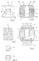
- the structure of such an actuator pole 5 according to the invention is shown in FIGS. 4 to 8 in different views.
- the invention provides for the geometry of the actuator pole 5 to approximate the circular shape, as a result of which a smaller magnetic field length can be achieved compared to the conventional rectangular shape.
- the circular shape can be adjusted with good approximation if, as can be seen from the front view of an actuator pole in FIG. 4, the core of the actuator pole 5 emerges from a hexagon wound from a strip-shaped sheet metal, the opposite tips of the hexagon being cut off.
- the two halves 5a, 5b formed are wound separately in the central part, so that two electromagnets are formed, the adjacent poles of which are a north and a south pole N, S (FIG. 8).
- the core of the pole 5 has a trapezoidal cut 11 on both sides formed by the end faces of the metal sheets 7.
- this creates the required winding space for the excitation coil 6 and, on the other hand, the cross-sectional area of the core is made square in the area of the surrounding winding, as the sectional illustration in FIG. 7 shows.
- the resulting advantages are that the actuator poles 3 of the three phases can be mounted very close to each other, which leads to a short construction of the entire actuator 3 and in the linear motor 1 to a larger stroke and that the winding length is minimal due to the square cross section .
- the L gradient d L / d s determines the force of the motor. It is state of the art to multiply d L / d s by forming teeth on the poles, the achievable speed decreasing but the power remaining constant.
- the pole faces 9 are toothed and the sheets 7 of the stator poles 4 are made thinner.
- the pole toothing 10 extends perpendicular to the direction of movement of the actuator pole, which is indicated by an arrow in FIG. 5, from one end of the pole 5 to the other end.
- the pole toothing is designed such that the width of the pole teeth relates to the width of the interdental spaces such as 7/12: 5/12, which is not clearly evident from FIGS. 5 and 6.
- the magnetic circuit which can be seen from the course of the magnetic field lines with the actuator and stator poles 4, 5 aligned in FIG. 8, is not oriented in the direction of movement of the actuator 3 as is usual, but perpendicular to it.
- the stator 2 no longer consists of long toothed metal sheets 7, as before, but that the stator poles 4 can be assembled from simple sheet metal pieces. This makes it very cheap to manufacture, and even pieces of waste can be used to produce transformer cores.
- the inventive design of the stator 2 and the stator poles 4 allows that the stator 2 can be bent to a limited extent and transport systems are possible over larger distances. In addition, the space between the stator poles 4 is free and gives a good possibility of cooling.
Abstract
Description
Die Erfindung betrifft einen Reluktanzmotor, bestehend aus einem stationären Element und einem zweiten, beweglichen Element, die beide eine Anzahl von Polen aufweisen, wobei die Pole eines Elementes durch Ein- und Ausschalten eines durch den Polen zugeordnete Erregerspulen fließenden elektrischen Stromes I in festgelegter Reihenfolge über zeitlich begrenzte Abschnitte magnetisierbar und dadurch zwischen benachbarten Polen des stationären Elementes und des beweglichen Elementes ein magnetischer Kreis erzeugt wird, der im Streben nach minimalem magnetischen Widerstand beziehungsweise nach maximaler Induktivität L benachbarte Pole der beiden Elemente zueinander auszurichten versucht und dabei zugeführte elektrische Energie in Bewegungsenergie umwandelt.The invention relates to a reluctance motor, consisting of a stationary element and a second, movable element, both of which have a number of poles, the poles of an element being switched on and off by an electrical current I flowing through the excitation coils assigned to the poles in a predetermined order Time-limited sections can be magnetized and a magnetic circuit is generated between adjacent poles of the stationary element and the movable element, which tries to align adjacent poles of the two elements in the pursuit of minimum magnetic resistance or maximum inductance L and thereby converts supplied electrical energy into kinetic energy .
Der Reluktanzmotor einfachster Form besteht aus einem Elektromagneten und einem Eisenkern, die relativ zueinander beweglich sind. Fließt durch die Spule der Induktivität L des Elektromagneten ein elektrischer Strom I, dann bilden Elektromagnet und Eisenkern einen geschlossenen magnetischen Kreis und zwischen Elektromagnet und Eisenkern wirkt eine Kraft F, die eine Verrückung ds bewirkt und die mechanische Energie F · ds erzeugt. Durch die Relativbewegung ändert sich der magnetische Widerstand des magnetischen Kreises und damit die Induktivität L der Spule, die für den magnetischen Fluß zuständig ist. Die Kraft zwischen Elektromagnet und Eisenkern, die eine Ausrichtung beider Körper anstrebt, ist
Bei konstantem Strom I ist die Kraft F dann konstant, wenn die Induktivität L mit dem zurückgelegten Weg ds linear zunimmt. Eine anziehende Kraft F existiert somit, wenn durch die Bewegung von Spule und Eisenkern die Induktivität L wachsen kann, d.h. wenn der bewegliche Pol sich mit dem stationären Pol ausrichtet. Die Induktivität L ist am größten, wenn beweglicher Pol und stationärer Pol so ausgerichtet sind, daß die Reluktanz ein Minimum hat.The simplest reluctance motor consists of an electromagnet and an iron core, which are movable relative to each other. If an electric current I flows through the coil of the inductance L of the electromagnet, then the electromagnet and iron core form a closed magnetic circuit and a force F acts between the electromagnet and the iron core, which causes a displacement d s and generates the mechanical energy F · d s . The relative movement changes the magnetic resistance of the magnetic circuit and thus the inductance L of the coil, which is responsible for the magnetic flux. The force between the electromagnet and the iron core, which aims to align both bodies, is
At a constant current I, the force F is constant when the inductance L increases linearly with the distance ds covered. An attractive force F therefore exists if the inductance L can grow due to the movement of the coil and iron core, ie if the movable pole aligns with the stationary pole. The inductance L is greatest when the movable pole and the stationary pole are aligned so that the reluctance is at a minimum.
Leistet der Reluktanzmotor mechanische Arbeit, so nimmt er elektrische Energie auf. Ist I konstant, so wird die aufgenommene elektrische Energie ![]()
![]()
Mit einer einzelnen Induktivität, d.h. mit einem einphasigen Reluktanzmotor läßt sich keine kontinuierliche Bewegung erzielen; erst mit zwei Induktivitäten, die abwechselnd, d.h. in zwei Phasen, arbeiten, wird eine kontinuierliche Bewegung erreicht. Während die eine, mechanische Arbeit verrichtende Spule magnetische Energie speichert, wird der Erregerstrom I der zweiten Spule heruntergeführt und die reversibel gespeicherte magnetische Energie zurückgewonnen.With a single inductance, i.e. continuous motion cannot be achieved with a single-phase reluctance motor; only with two inductors that alternate, i.e. in two phases, working, a continuous movement is achieved. While the one mechanical work coil stores magnetic energy, the excitation current I of the second coil is brought down and the reversibly stored magnetic energy is recovered.
Ein kontinuierlich arbeitendes Antriebssystem muß also aus mindestens zwei periodisch aktivierbaren Teilsystemen (Phasen) bestehen, deren Perioden im wesentlichen zwei Abschnitte aufweisen. Während des ersten Abschnitts wird elektrische Energie zugeführt und in mechanische Energie (Bewegung) und magnetische Energie (reversibel im Magnetfeld gespeichert) umgewandelt, wobei zur Erzeugung einer konstanten Kraft die Induktivität L linear zunehmen muß: dL/ds > 0. Während des zweiten Abschnitts wird die mit dem Strom I gekoppelte magnetische Energie in elektrische Energie zurückgewandelt. Soll der Motor auch in Gegenrichtung laufen, so gilt aus Symmetriegründen, daß die Induktivität L mit Beginn des zweiten Abschnitts linear abnimmt. dL/ds < 0. Der Verlauf der Induktivität L folgt also einer Dreiecksfunktion; dieser Verlauf gilt für beide Teilsysteme, wobei die Periode des ersten Teilsystems um 1/2 Periode phasenverschoben ist.A continuously operating drive system must therefore consist of at least two periodically activatable subsystems (phases), the periods of which essentially have two sections. During the first section, electrical energy is supplied and converted into mechanical energy (movement) and magnetic energy (reversible in Magnetic field stored) converted, in order to generate a constant force, the inductance L must increase linearly: dL / ds> 0. During the second section, the magnetic energy coupled with the current I is converted back into electrical energy. If the motor is also to run in the opposite direction, then for symmetry reasons it applies that the inductance L decreases linearly at the beginning of the second section. dL / ds <0. The course of the inductance L thus follows a triangular function; this course applies to both subsystems, the period of the first subsystem being out of phase by 1/2 period.
Die Nachteile des Zwei-Phasensystems bestehen darin, daß keine gezielte Richtungssteuerung möglich ist, weil die Ableitung der Induktivitätsfunktion im Umkehrpunkt nicht stetig ist, und daß nach Überschreiten des Umkehrpunktes, in dem die Induktivität L maximal ist, der Strom nicht sprunghaft auf Null zurückführbar ist. Da die Steigung der Induktivitätsfunktion in diesem Abschnitt negativ ist (dL/ds < 0) ergibt sich eine bremsende Kraft und das System funktioniert als Generator, wobei ein Teil der erzeugten mechanischen Energie in elektrische Energie zurückverwandelt wird. Die Laufruhe des Motors leidet darunter.The disadvantages of the two-phase system are that no targeted directional control is possible because the derivation of the inductance function at the reversal point is not continuous, and that after the reversal point in which the inductance L is at a maximum, the current cannot be jumped back to zero . Since the slope of the inductance function in this section is negative (dL / ds <0), there is a braking force and the system functions as a generator, with some of the mechanical energy generated being converted back into electrical energy. The smoothness of the engine suffers.
Diese Nachteile lassen sich mit einer dritten Phase, die eine dritte Spule erregt, beseitigen. Die Perioden der drei Phasen haben gegeneinander eine zeitliche Verschiebung von 1/3 Periode, laufen parallel und führen im Idealfall zu einer homogenen Kraftwirkung.These disadvantages can be eliminated with a third phase which excites a third coil. The periods of the three phases have a time shift of 1/3 period against each other, run in parallel and ideally lead to a homogeneous force effect.
In der PCT WO 90/00831 ist die Veränderung der Induktivität L einer Phase in Abhängigkeit vom Drehwinkel eines Rotationsmotors in idealisierter Form dargestellt. Die Induktivität L zeigt einen für eine kontinuierliche Bewegung sehr ungünstigen Verlauf. Aufgrund des dargestellten Induktivitätsverlaufes läßt es sich nicht vermeiden, daß nach Überschreiten des Umkehrpunktes während des Abfalls von Lmax auf Lmin ein Bremsdrehmoment auftritt, das die Laufruhe des Motors wesentlich beeinträchtigt.In PCT WO 90/00831, the change in inductance L of a phase is a function of the angle of rotation of a rotary motor in an idealized form. The inductance L shows a course which is very unfavorable for a continuous movement. Because of the inductance curve shown, it cannot be avoided that after the reversal point has been exceeded, a braking torque occurs during the drop from L max to L min , which significantly impairs the smooth running of the motor.
Weiterhin ist in der PCT WO 90/11641 der Verlauf von Induktivität L und Strom I einer Phase eines Reluktanzmotors in Abhängigkeit von der Umdrehungszeit dargestellt. Daraus geht hervor, daß der elektrische Strom I seinen Sollwert bereits erreicht, wenn die Induktivität L noch konstant ist und ihren Minimalwert Lmin hat, so daß wegen ![]()
![]()
Der Erfindung liegt deshalb die Aufgabe zugrunde, den periodischen Verlauf von Erregerstrom I und Induktivität L zu optimieren und die geometrische Anordnung und Ausbildung der Pole des stationären Elementes und des beweglichen Elementes des Reluktanzmotors darauf abzustimmen und so auszuführen, daß eine hohe Laufruhe, d.h. eine konstante Kraftwirkung, erreicht wird und außerdem eine wirtschaftliche Herstellung derartiger Motoren gewährleistet ist.The invention is therefore based on the object of optimizing the periodic course of excitation current I and inductance L and of coordinating the geometric arrangement and design of the poles of the stationary element and of the movable element of the reluctance motor and of executing them in such a way that they run very smoothly, ie constant Power effect is achieved and also an economical production of such motors is guaranteed.
Diese Aufgabe wird erfindungsgemäß dadurch gelöst, daß die geometrische Anordnung und Ausbildung der Pole des stationären Elementes und des beweglichen Elementes des Reluktanzmotors und der periodische Verlauf von Erregerstrom I und Induktivität L einer Phase während der Bewegung des Reluktanzmotors so aufeinander abstimmbar sind, daß im ersten Abschnitt der Periode die Induktivität L konstant und minimal Lmin ist und der Erregerstrom I von Null auf den Sollwert Isoll ansteigt, daß im zweiten Abschnitt der Periode die Induktivität L von dem Minimalwert Lmin auf den Maximalwert Lmax linear zunimmt bei konstantem Erregerstrom Isoll, daß im dritten Abschnitt der Periode die Induktivität L den Maximalwert Lmax beibehält und der Erregerstrom I auf Null abfällt, und daß im vierten Abschnitt der Periode die Induktivität L von dem Maximalwert Lmax auf den Ausgangswert Lmin zurückgeht und der Erregerstrom I Null ist.This object is achieved in that the geometric arrangement and design of the poles of the stationary element and the movable element of the reluctance motor and the periodic course of excitation current I and inductance L of a phase during the movement of the reluctance motor are so coordinated that in the first section the period the inductance L is constant and minimum L min and the excitation current I increases from zero to the setpoint I soll , that in the second section of the period the inductance L increases linearly from the minimum value L min to the maximum value L max with constant excitation current I soll that in the third section of the period the inductance L maintains the maximum value L max and the excitation current I drops to zero, and that in the fourth section of the period the inductance L decreases from the maximum value L max to the initial value L min and the excitation current I is zero .
Nach der Erfindung ist vorgesehen, daß bei dem durch drei Phasen erregbaren Reluktanzmotor der erste Abschnitt zeitlich 1/12 der Periode, der zweite Abschnit 1/3 der Periode, der dritte Abschnitt 1/4 der Periode und der vierte Abschnitt 1/3 der Periode betragen.According to the invention it is provided that in the reluctance motor which can be excited by three phases, the first section takes 1/12 of the period, the
Ein weiteres Merkmal der Erfindung besteht darin, daß jeder Pol des beweglichen Elementes mit Erregerspulen versehen ist, wobei der Pol die Form eines aus Blechen gewickelten Sechsecks aufweist, dessen gegenüberliegende Spitzen so abgeschnitten sind, daß zwei Hälften entstehen, die getrennt bewickelbar sind, und daß die von den Stirnseiten der Bleche gebildeten Seitenflächen der Pole von den Polflächen ausgehende und nach innen verlaufende trapezförmige Einschnitte aufweisen.A further feature of the invention is that each pole of the movable element is provided with excitation coils, the pole being in the form of a hexagon wound from sheet metal, the opposite tips of which are cut off to form two halves which can be wound separately, and in that the side surfaces of the poles formed by the end faces of the sheets have trapezoidal incisions extending from the pole surfaces and running inwards.
Als vorteilhaft erweist sich, daß der magnetische Kreis senkrecht zur Bewegungsrichtung des beweglichen Elementes orientiert ist.It proves to be advantageous that the magnetic circuit is oriented perpendicular to the direction of movement of the movable element.
Außerdem sieht die Erfindung vor, daß die Orientierung der lamellierten Bleche des stationären Elementes und des beweglichen Elementes gekreuzt ist.In addition, the invention provides that the orientation of the laminated sheets of the stationary element and the movable element is crossed.
Die mit der Erfindung erzielten Vorteile bestehen insbesondere darin, daß ein Reluktanzmotor entwickelt wurde, der eine kontinuierlich und konstant wirkende Kraft erzeugt und somit eine hohe Laufruhe aufweist, und der aufgrund der geometrischen Ausbildung der Pole und der Orientierung der magnetischen Feldlinien einfach aufgebaut und wirtschaftlich herstellbar ist. Außerdem lassen sich durch die erfindungsgemäße Ausbildung des Reluktanzmotors lang ausgedehnte Transportsysteme realisieren, und aufgrund der sehr großen Kraft bei kleinen Geschwindigkeiten findet der Motor vorteilhaft Anwendung als Generator für langsam laufende Antriebe (Windgenerator ohne Getriebe).The advantages achieved by the invention consist in particular in the fact that a reluctance motor has been developed which generates a continuously and constantly acting force and thus has a high level of smoothness, and which, due to the geometrical design of the poles and the orientation of the magnetic field lines, is simple to construct and economical to produce is. In addition, the embodiment of the reluctance motor according to the invention enables long-range transport systems to be implemented, and because of the very large force at low speeds, the motor is advantageously used as a generator for slow-running drives (wind generator without gear).
Die Erfindung wird anhand eines Ausführungsbeispiels, das in der Zeichnung dargestellt ist, nachfolgend näher beschrieben.The invention is described in more detail below using an exemplary embodiment which is illustrated in the drawing.
Es zeigt
- Fig. 1
- eine schematische Darstellung eines Dreiphasen-Linearreluktanzmotors in Seitenansicht,
- Fig. 2
- den zeitlichen Verlauf von Induktivität L und Erregerstrom I einer Phase während einer Periode,
- Fig. 3a bis 3d
- den Bewegungsablauf eines Aktuatorpoles innerhalb des Stators und der zugehörige ortsabhängige Verlauf der Induktivität L,
- Fig. 4
- die Vorderansicht eines erfindungsgemäßen Aktuatorpoles,
- Fig. 5
- die Seitenansicht des Aktuatorpoles aus Fig. 4,
- Fig. 6
- die Draufsicht von oben auf den Aktuatorpol aus Fig. 4,
- Fig. 7
- den Schnitt A-A aus Fig. 5 und
- Fig. 8
- den Verlauf der magnetischen Feldlinien bei ausgerichtetem Aktuator- und Statorpol.
- Fig. 1
- 1 shows a schematic illustration of a three-phase linear reluctance motor in a side view,
- Fig. 2
- the time course of inductance L and excitation current I of a phase during a period,
- 3a to 3d
- the sequence of movements of an actuator pole within the stator and the associated location-dependent profile of the inductance L,
- Fig. 4
- the front view of an actuator pole according to the invention,
- Fig. 5
- the side view of the actuator pole of Fig. 4,
- Fig. 6
- the top view of the actuator pole from FIG. 4,
- Fig. 7
- the section AA of Fig. 5 and
- Fig. 8
- the course of the magnetic field lines with the actuator and stator poles aligned.
Der elektrische Reluktanzmotor ist sowohl als Rotationsals auch als Linearmotor bekannt und gleichermaßen im Einsatz. Beiden Motoren ist gemeinsam, daß sie aus einem stationären Element, nachfolgend als Stator bezeichnet, und aus einem beweglichen Element bestehen, die beide mit einer Reihe von Polen ausgestattet sind. Bei dem Rotationsmotor ist der Stator als Kreisring ausgebildet, in dessen Inneren das bewegliche Element Drehbewegungen ausführt und dementsprechend als Rotor bezeichnet wird. Bei dem Linearmotor ist der Stator gestreckt ausgebildet und das bewegliche Element, nachfolgend als Aktuator bezeichnet, führt innerhalb des Stators Linearbewegungen aus.The electrical reluctance motor is known both as a rotary and a linear motor and is used equally. It is common to both motors that they consist of a stationary element, hereinafter referred to as the stator, and of a movable element, both of which are equipped with a series of poles. In the rotary motor, the stator is designed as a circular ring, in the interior of which the movable element executes rotary movements and is accordingly referred to as a rotor. In the linear motor, the stator is elongated and the movable element, hereinafter referred to as the actuator, performs linear movements within the stator.
Die Erfindung wird nachfolgend anhand eines Linearmotors 1 beschrieben, wobei die erfindungsgemäßen Merkmale auch auf einen Rotationsmotor übertragbar sind.The invention is described below with reference to a
Fig. 1 zeigt in schematischer Darstellung eine Seitenansicht eines mit 1 bezeichneten Linear-Reluktanzmotors, dessen Stator 2 kammartig vorspringende Pole 4 aufweist, die auf entsprechenden Trägern 2a, 2b mit beliebigen magnetischen Eigenschaften, beispielsweise Beton, Kunststoff oder ähnlichen Materialien befestigt sind. Zwischen den Statorpolen 4 ist der in Pfeilrichtung bewegliche Aktuator 3 angeordnet, der in dem als Ausführungsbeispiel dargestellten Dreiphasen-Reluktanzmotor 1 aus drei miteinander verbundenen Aktuatorpolen 5 besteht. Bei diesem Ausführungsbeispiel sind die Aktuatorpole 5 mit Erregerspulen 6 versehen und nicht wie allgemein üblich die Statorpole 4. Diese Ausführung erweist sich bei langgestreckten Linearmotoren 1, d.h. bei Motoren mit großem Hub, als besonders vorteilhaft, da nicht die Vielzahl der Statorpole 4, sondern nur die drei Aktuatorpole 5 mit Kupferdraht bewickelt sind, was zu einer Ersparnis an Draht und Arbeitszeit führt. Allerdings wird bei dem dargestellten Ausführungsbeispiel die zugeführte elektrische Energie auf drei Aktuatorpole 5 konzentriert, was eine höhere Stromdichte zur Folge hat und zu einer unerwünschten Erwärmung führen kann; außerdem muß der Erregerstrom I über bekannte Anschlußelemente, die nicht in der Zeichnung dargestellt sind, den Erregerspulen 6 der beweglichen Aktuatorpole 5 zugeführt werden.1 shows a schematic illustration of a side view of a linear reluctance motor denoted by 1, the
Bekanntlich besteht der magnetische Kreis des Reluktanzmotors 1 aus der Reihenschaltung eines niedrigen magnetischen Widerstandes mit konstantem Wert, der durch den Kern von Erregerspule 6 und Statorpol 4 erzeugt wird und eines hohen magnetischen Widerstandes mit periodisch veränderlichem Wert, der durch den Luftspalt 8 zwischen Statorpol 4 und bewegtem Aktuatorpol 5 erzeugt wird. Um eine größere Laufruhe des Reluktanzmotors 1 bzw. eine konstante Kraft und eine bessere Energieausnutzung zu erzielen, sieht die Erfindung vor, den magnetischen Kreis so auszuführen, daß der magnetische Widerstand und damit die zu ihm umgekehrt proportionale Induktivität L einer Phase periodisch so veränderbar ist, daß sie zu Beginn der Periode konstant und minimal Lmin ist, dann linear von dem Minimalwert Lmin auf den Maximalwert Lmax ansteigt, danach konstant bleibt und schließlich wieder auf den minimalen Ausgangswert Lmin abnimmt, wobei der zeitliche Verlauf des Erregerstromes I auf den Verlauf der Induktivität L abgestimmt ist.As is known, the magnetic circuit of the
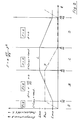
Fig. 2 zeigt in idealisierter Form den erfindungsgemäßen Verlauf von Induktivität L und Erregerstrom I einer Phase eines dreiphasigen Reluktanzmotors 1 während einer Periode. Zu diesem Diagramm ist anzumerken, daß der Verlauf des Stromes I zeitabhängig ist, während der Verlauf der Induktivität L ortsabhängig ist und das Diagramm den Stromverlauf bei maximaler, konstanter Geschwindigkeit zeigt. Auf den ortsabhängigen Verlauf der Induktivität L wird in den nachfolgenden Fig. 3a bis 3d noch eingegangen. Wie aus Fig. 2 hervorgeht, ist die Periode in vier zeitlich unterschiedlich große Abschnitte A, B, C, D unterteilt, in denen Induktivität L und Erregerstrom I vorgegebene charakteristische Werte annehmen:
- Abschnitt A:
Für 1/12 der Periode ist die Induktivität L konstant und minimal, während der Erregerstrom I von Null auf seinen Sollwert Isoll ansteigt. Die dazu benötigte Zeit beträgt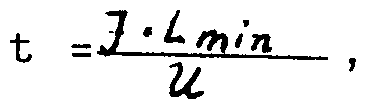
die Erregerspule 6 angelegte Erregerspannung bedeutet. Während dieser Zeit leistet die Phase desMotors 1, wie vorgesehen, keine Kraft, denn aus L = const folgt dL/ds = 0 und daraus folgt K = 0. - Abschnitt B: Die Induktivität
L steigt während 1/3 der Periode linear von dem Minimalwert Lmin auf einen Maximalwert Lmax an, während der Erregerstrom I auf seinem Sollwert Isoll konstant gehalten wird. Der Induktivitätsanstieg kommt durch die Bewegung des Aktuatorpoles 5auf den Statorpol 4 hin zustande, was in den folgenden Fig. 3a bis 3d noch gezeigt wird. Während des Abschnitts B wird eine Kraft erzeugt, denn aus I > 0 und dL/ds > 0 folgt K > 0. - Abschnitt C: Die Induktivität L bleibt während 1/4 der Periode konstant bei Lmax und der Erregerstrom I wird auf Null herabgeführt. Die dazu benötigte Zeit

- Abschnitt D: Die Induktivität
L nimmt während 1/3 der Periode linear auf den Ausgangswert Lmin ab und, der Erregerstrom I bleibt ausgeschaltet. Eine Kraftwirkung entsteht wie vorgesehen nicht, denn wenn kein Strom fließt, kann keine Kraft entstehen.
- Section A: For 1/12 of the period, the inductance L is constant and minimal, while the excitation current I increases from zero to its nominal value I soll . The time required for this is
excitation coil 6. During this time, the phase of themotor 1, as provided, does not exert any force, because L = const results in dL / ds = 0 and K = 0. - Section B: The inductance L increases linearly from the minimum value L min to a maximum value L max during 1/3 of the period, while the excitation current I is kept constant at its target value I soll . The increase in inductance is caused by the movement of the
actuator pole 5 towards thestator pole 4, which is shown in the following FIGS. 3a to 3d. A force is generated during section B because I> 0 and dL / ds> 0 result in K> 0. - Section C: The inductance L remains constant at L max for 1/4 of the period and the excitation current I is reduced to zero. The time required for this
- Section D: The inductance L decreases linearly to the initial value L min during 1/3 of the period and the excitation current I remains switched off. As intended, there is no force effect, because if no current flows, no force can arise.
Wie aus dieser Darstellung hervorgeht, erzeugt eine Phase nur während 1/3 ihrer Periode eine Kraft. Im Zusammenwirken der drei Phasen des dreiphasigen Reluktanzmotors 1 wird eine kontinuierlich und konstant wirkende Kraft während der gesamten Periode erzeugt, ohne daß bremsende Effekte infolge nicht abgestimmter Induktivitäts- und Erregerstromverläufe die Laufruhe des Reluktanzmotors 1 beeinträchtigen.As can be seen from this illustration, a phase generates a force only during 1/3 of its period. In the interaction of the three phases of the three-
In den Fig. 3a bis 3d ist schematisch der Ablauf der Bewegung eines Aktuatorpoles 5 innerhalb der Statorpole 4 während einer Periode sowie der entsprechende ortsabhängige Verlauf der Induktivität L dargestellt. Die Ausgangsstellung des Aktuatorpoles 5 ist jeweils durch das ausgezogene Rechteck, die Endstellung des Aktuatorpoles 5 durch das gestrichelte Rechteck und die Bewegungsrichtung durch den Pfeil gekennzeichnet.3a to 3d schematically show the course of the movement of an
Im Abschnitt A (Fig. 3a) bewegt sich der Aktuatorpol 5 gerade außerhalb zweier, nebeneinander angeordneter Statorpole 4; die Induktivität L bleibt während der Bewegung annähernd konstant und minimal: Lmin.In section A (FIG. 3a), the
Im Abschnitt B (Fig. 3b) bewegt sich der Aktuatorpol 5 beispielsweise mit seiner rechten Kante von links in den Bereich zweier gegenüberliegender Statorpole 4, bis die rechten Kanten von Aktuatorpol 5 und gegenüberliegenden Statorpolen 4 in einer Flucht liegen; die Induktivität L nimmt linear von Lmin auf Lmax zu.In section B (FIG. 3b), the
Im Abschnitt C (Fig. 3c) bewegt sich der Aktuatorpol 5 innerhalb des Bereiches gegenüberliegender Statorpole 4 so weit nach rechts weiter, bis seine linke Kante mit den linken Kanten der Statorpole 4 fluchtet; die Induktivität bleibt konstant und ist maximal Lmax.In section C (FIG. 3c), the
Im Abschnitt D (Fig. 4d) bewegt sich der Aktuatorpol 5 aus dem Bereich der gegenüberliegenden Statorpole 4 hinaus und kehrt in seine Ausgangsstellung gemäß Fig. 3a wieder zurück; die Induktivität L nimmt linear von Lmax auf Lmin ab.In section D (FIG. 4d), the
Ein Reluktanzmotor, der dieses Verhalten zeigt, ist der in Fig. 1 dargestellte Linearmotor 1 mit den erfindungsgemäß ausgebildeten und angeordneten Stator- und Aktuatorpolen 4, 5. Erfindungsgemäß verhält sich die Breite x₁ der Polfläche 9 eines Statorpoles 4 zu dem Abstand x₂ zweier benachbarter Statorpole 4 wie 1:2. Die Breite x₃ der Polfläche 9 eines Aktuatorpoles 5 wird durch den Abstand x₂ zweier benachbarter Statorpole 4 bestimmt und ist um die in dem Abschnitt A von dem Aktuatorpol 5 zurückgelegte Weglänge kleiner als x₂, d.h.![]()
![]()
Neben der geometrischen Anordnung der Pole 4, 5 von Stator 2 und Aktuator 3 zur Realisierung des erfindungsgemäßen Induktivitätsverlaufes ist auch die Ausbildung der Pole 4, 5 für die Güte des Reluktanzmotors 1 von entscheidender Bedeutung. Für die Herstellung der Pole 4, 5 werden magnetisch leitende Werkstoffe, beispielsweise Eisen, Ferrite oder amorphe Werkstoffe für den magnetischen und Kupfer für den elektrischen Kreis verwendet. Diese Werkstoffe sind nicht ideal. Kupfer hat einen ohmschen Widerstand und wandelt elektrische Energie in Wärme um. Die magnetisch leitenden Werkstoffe, ob hart oder weich, sind nicht beliebig stark magnetisierbar und erzeugen beim Ummagnetisieren ebenfalls Wärme.In addition to the geometrical arrangement of the
Zur Minderung von Wirbelströmen können die Kerne der Stator- und Aktuatorpole 4, 5 aus gegeneinander isolierten, miteinander verklebten Blechen aus magnetisch leitenden Werkstoffen, in der Regel Eisen, zusammengesetzt sein. Der Aufbau eines solchen erfindungsgemäßen Aktuatorpoles 5 ist in den Fig. 4 bis 8 in verschiedenen Ansichten dargestellt. Zur Minimierung der ohmschen Verluste ist erfindungsgemäß vorgesehen, die Geometrie des Aktuatorpoles 5 der Kreisform anzunähern, wodurch gegenüber der üblichen rechteckigen Form eine kleinere Magnetfeldlänge erreichbar ist. Die Kreisform läßt sich mit guter Annäherung einstellen, wenn, wie aus der Vorderansicht eines Aktuatorpoles in Fig. 4 ersichtlich ist, der Kern des Aktuatorpoles 5 aus einem aus bandförmigem Blech gewickelten Sechseck hervorgeht, wobei die gegenüberliegenden Spitzen des Sechsecks abgeschnitten sind. Die beiden entstandenen Hälften 5a, 5b sind im Mittelteil getrennt bewickelt, so daß zwei Elektromagnete entstehen, deren nebeneinander liegende Pole jeweils ein Nord- und ein Südpol N, S sind (Fig. 8).To reduce eddy currents, the cores of the stator and
Wie aus der Seitenansicht des Aktuatorpoles 5 in Fig. 5 hervorgeht, weist der Kern des Poles 5 auf beiden von den Stirnseiten der Bleche 7 gebildeten Seiten einen trapezförmigen Einschnitt 11 auf. Dadurch entsteht einmal der benötigte Wickelraum für die Erregerspule 6 und zum anderen wird dadurch die Querschnittsfläche des Kerns im Bereich der umschließenden Wicklung quadratisch ausgebildet, wie die Schnittdarstellung in Fig. 7 zeigt. Die sich daraus ergebenden Vorteile bestehen darin, daß die Aktuatorpole 3 der drei Phasen sehr dicht nebeneinander montierbar sind, was zu einem kurzen Aufbau des gesamten Aktuators 3 und bei dem Linearmotor 1 zu einem größeren Hub führt und daß die Wicklungslänge aufgrund des quadratischen Querschnitts minimal wird.As can be seen from the side view of the
Bei gegebener Polfläche bestimmt der L-Gradient dL/ds die Kraft des Motors. Es ist Stand der Technik, durch die Ausbildung von Zähnen auf den Polen dL/ds zu vervielfachen, wobei die erreichbare Geschwindigkeit absinkt, die Leistung jedoch konstant bleibt. Die Polflächen 9 werden gezahnt und die Bleche 7 der Statorpole 4 dünner ausgeführt. Nach Fig. 5 und 6 erstreckt sich die Polzahnung 10 senkrecht zur Bewegungsrichtung des Aktuatorpols, die in Fig. 5 durch einen Pfeil angezeigt ist, von einem Ende des Poles 5 bis zum anderen Ende. Die Polzahnung ist so ausgebildet, daß die Breite der Polzähne sich zu der Breite der Zahnzwischenräume wie 7/12 : 5/12 verhält, was aus den Fig. 5 und 6 nicht eindeutig hervorgeht. Dadurch verringert sich die wirksame Polfläche 9; da jedoch die beim Abschneiden der Sechseckspitzen entstehenden Polflächen 9 des Aktuatorpoles 5 gegenüber dem auf quadratischen Querschnitt gefertigten Mittelbereich des Kernes aufgeweitet sind, wird erreicht, daß die aktive Querschnittsfläche im gesamten magnetischen Kreis annähnernd konstant bleibt und keine partiellen Sättigungen auftreten können.For a given pole area, the L gradient d L / d s determines the force of the motor. It is state of the art to multiply d L / d s by forming teeth on the poles, the achievable speed decreasing but the power remaining constant. The pole faces 9 are toothed and the
Der magnetische Kreis, der aus dem Verlauf der magnetischen Feldlinien bei ausgerichtetem Aktuator- und Statorpol 4, 5 in Fig. 8 erkennbar ist, ist nicht wie üblich in Bewegungsrichtung des Aktuators 3 orientiert, sondern senkrecht dazu. Dies hat zur Folge, daß der Stator 2 nicht mehr wie bisher aus langen gezahnten Blechen 7 besteht, sondern daß die Statorpole 4 aus einfachen Blechstücken zusammensetzbar sind. Die Herstellung wird dadurch sehr billig, es können sogar Abfallstücke verwendet werden, die bei der Produktion von Transformatorenkernen anfallen. Die erfindungsgemäße Ausbildung des Stators 2 und der Statorpole 4 erlaubt es, daß der Stator 2 in begrenztem Maß gebogen werden kann und Transportsysteme über größere Distanzen möglich sind. Außerdem ist der Raum zwischen den Statorpolen 4 frei und ergibt eine gute Möglichkeit der Kühlung.The magnetic circuit, which can be seen from the course of the magnetic field lines with the actuator and
Eine vorteilhafte Folgerung dieser Konstruktion ist dadurch gegeben, daß die Orientierung der am magnetischen Fluß beteiligten Stator- und Aktuatorbleche 7 gekreuzt ausgeführt werden kann. Dadurch wird es möglich, daß die geschlossenen magnetischen Feldlinien nicht von einem zu einem anderen durch die Isolierung getrennten Blech 7 wechseln müssen, wenn die parallelen Bleche 7 von Stator- und Aktuatorpol 4, 5 nicht richtig zueinander justiert sind. Bei der erfindungsgemäßen gekreuzten Ausführung der Stator- und Aktuatorbleche 7 finden die magnetischen Feldlinien immer das "richtige" Blech 7.An advantageous consequence of this construction is that the orientation of the stator and
Claims (5)
Applications Claiming Priority (2)
| Application Number | Priority Date | Filing Date | Title |
|---|---|---|---|
| DE19934311664 DE4311664A1 (en) | 1993-04-08 | 1993-04-08 | Reluctance motor |
| DE4311664 | 1993-04-08 |
Publications (2)
| Publication Number | Publication Date |
|---|---|
| EP0619640A2 true EP0619640A2 (en) | 1994-10-12 |
| EP0619640A3 EP0619640A3 (en) | 1995-08-16 |
Family
ID=6485111
Family Applications (1)
| Application Number | Title | Priority Date | Filing Date |
|---|---|---|---|
| EP94105387A Ceased EP0619640A3 (en) | 1993-04-08 | 1994-04-07 | Variable reluctance motor. |
Country Status (2)
| Country | Link |
|---|---|
| EP (1) | EP0619640A3 (en) |
| DE (1) | DE4311664A1 (en) |
Families Citing this family (4)
| Publication number | Priority date | Publication date | Assignee | Title |
|---|---|---|---|---|
| DE19604645A1 (en) * | 1996-02-08 | 1997-08-14 | Stemme Otto | Linear electric drive with soft magnetic core flanges and toothed rods e.g. for machine tools |
| DE19861223B4 (en) * | 1998-10-12 | 2006-06-01 | Sew-Eurodrive Gmbh & Co. Kg | Linear switched reluctance motor |
| DE102017127021A1 (en) | 2017-11-16 | 2019-05-16 | Technische Universität Wien | Reluctance linear actuator and thus implemented tools / drives |
| DE102022117759A1 (en) | 2022-07-15 | 2024-01-18 | Technische Universität Wien | Linear actuator with optimized inductance and method for winding and connecting coils |
Citations (6)
| Publication number | Priority date | Publication date | Assignee | Title |
|---|---|---|---|---|
| DE2725638A1 (en) * | 1976-06-10 | 1977-12-22 | John Workman | POL CARRYING DEVICE FOR AN ELECTRIC DC MACHINE |
| DE2813784A1 (en) * | 1977-03-30 | 1978-11-16 | Chloride Group Ltd | ELECTRIC DRIVE SYSTEM |
| FR2403197A1 (en) * | 1977-09-14 | 1979-04-13 | Exxon Research Engineering Co | PRINTING MACHINE WITH STEP LINEAR MOTOR |
| EP0123617A2 (en) * | 1983-04-20 | 1984-10-31 | Jacques Henri Jarret | Magnetic ring for rectilinear generators with free pistons |
| WO1990000831A1 (en) * | 1988-07-14 | 1990-01-25 | The University Court Of The University Of Glasgow | Motor drive system |
| WO1990011641A1 (en) * | 1989-03-28 | 1990-10-04 | Pacific Scientific Company | Electronically commutated reluctance motor |
Family Cites Families (2)
| Publication number | Priority date | Publication date | Assignee | Title |
|---|---|---|---|---|
| FR2510838A1 (en) * | 1981-07-28 | 1983-02-04 | Od Polt Institut | Double-coordinate linear electric drive - has two=part moving core with ferromagnetic bridge and vertical slots for control windings |
| GB2105536B (en) * | 1981-09-08 | 1985-09-18 | Chloride Group Ltd | A multi-phase switched variable-reluctance motor |
-
1993
- 1993-04-08 DE DE19934311664 patent/DE4311664A1/en not_active Ceased
-
1994
- 1994-04-07 EP EP94105387A patent/EP0619640A3/en not_active Ceased
Patent Citations (6)
| Publication number | Priority date | Publication date | Assignee | Title |
|---|---|---|---|---|
| DE2725638A1 (en) * | 1976-06-10 | 1977-12-22 | John Workman | POL CARRYING DEVICE FOR AN ELECTRIC DC MACHINE |
| DE2813784A1 (en) * | 1977-03-30 | 1978-11-16 | Chloride Group Ltd | ELECTRIC DRIVE SYSTEM |
| FR2403197A1 (en) * | 1977-09-14 | 1979-04-13 | Exxon Research Engineering Co | PRINTING MACHINE WITH STEP LINEAR MOTOR |
| EP0123617A2 (en) * | 1983-04-20 | 1984-10-31 | Jacques Henri Jarret | Magnetic ring for rectilinear generators with free pistons |
| WO1990000831A1 (en) * | 1988-07-14 | 1990-01-25 | The University Court Of The University Of Glasgow | Motor drive system |
| WO1990011641A1 (en) * | 1989-03-28 | 1990-10-04 | Pacific Scientific Company | Electronically commutated reluctance motor |
Non-Patent Citations (3)
| Title |
|---|
| CONFERENCE RECORD OF THE 1988 IEEE INDUSTRY APPLICATIONS SOCIETY ANNUAL MEETING, 2. Oktober 1988, PITTSBURGH, PENNSYLVANIA USA Seiten 515 - 519, XP000092903 X.MANG & AL. 'Design and performance of an interactive personal computer controller for switched reluctance motor drives' * |
| IEEE TRANSACTIONS ON INDUSTRIAL ELECTRONICS, Bd.36, Nr.4, November 1989, NEW-YORK USA Seiten 523 - 529, XP000071490 P.N.MATERU & AL. 'Steady-state analysis of the variable-speed switched-reluctance motor drive' * |
| PESC'89 RECORD, Bd.1, 26. Juni 1989, MILWAUKEE,WI USA Seiten 3 - 10, XP000044282 H.LE-HUY & AL. 'A novel unipolar converter for switched reluctance motor' * |
Also Published As
| Publication number | Publication date |
|---|---|
| EP0619640A3 (en) | 1995-08-16 |
| DE4311664A1 (en) | 1994-10-13 |
Similar Documents
| Publication | Publication Date | Title |
|---|---|---|
| EP0762619B1 (en) | Method and device for reducing cogging in an electric motor | |
| EP1064712B1 (en) | Multi-phase transverse flux machine | |
| DE2515133B2 (en) | Reluctance machine arrangement | |
| EP1000458A1 (en) | Electrical machine with soft-magnetic teeth and a method for producing same | |
| DE69936166T2 (en) | Laminated core for a switched reluctance machine | |
| DE102012212637A1 (en) | Casting electrical coil | |
| EP1314236B1 (en) | Electric machine for high magnetic reversal frequencies | |
| EP2751906B1 (en) | Electric motor with ironless winding | |
| EP3545610B1 (en) | Synchronous machine having magnetic rotary field reduction and flux concentration | |
| DE10220822B4 (en) | Linear motor | |
| DE2623234B2 (en) | ||
| DE102009057446B4 (en) | Electric machine | |
| DE2030789C3 (en) | Reluctance machine | |
| DE60125194T2 (en) | Wanderfeld synchronous motor | |
| EP0612446B1 (en) | Linear motor or generator and stator therefor | |
| EP2605367A1 (en) | Transversal flux machine with Halbach arrays | |
| EP0619640A2 (en) | Variable reluctance motor | |
| EP0134827A1 (en) | Electromagnetic drive for continuous and stepwise linear or rotary movements | |
| DE3401163A1 (en) | Electrical machines having permanent-magnet excitation, and as a reluctance version in a laminated excitation arrangement | |
| DE19960168A1 (en) | Generator-motor combination | |
| WO2014071960A1 (en) | Electric motor with improved inductance and method for winding and interconnecting coils | |
| DE2322903A1 (en) | LINEAR SYNCHRONOUS MOTOR FOR HIGH SPEED VEHICLES | |
| DE4302807C2 (en) | Multi-phase electrical machine and process for its manufacture | |
| DE2842195C3 (en) | Synchronous motor with permanent magnetic rotor | |
| DE2727471C3 (en) | Electronically commutated reluctance motor |
Legal Events
| Date | Code | Title | Description |
|---|---|---|---|
| PUAI | Public reference made under article 153(3) epc to a published international application that has entered the european phase |
Free format text: ORIGINAL CODE: 0009012 |
|
| AK | Designated contracting states |
Kind code of ref document: A2 Designated state(s): AT BE CH DE DK ES FR GB IE IT LI NL PT SE |
|
| PUAL | Search report despatched |
Free format text: ORIGINAL CODE: 0009013 |
|
| AK | Designated contracting states |
Kind code of ref document: A3 Designated state(s): AT BE CH DE DK ES FR GB IE IT LI NL PT SE |
|
| 17P | Request for examination filed |
Effective date: 19960213 |
|
| 17Q | First examination report despatched |
Effective date: 19960326 |
|
| STAA | Information on the status of an ep patent application or granted ep patent |
Free format text: STATUS: THE APPLICATION HAS BEEN REFUSED |
|
| 18R | Application refused |
Effective date: 19980108 |