EP0619617A1 - Dual bandpass microwave filter - Google Patents
Dual bandpass microwave filter Download PDFInfo
- Publication number
- EP0619617A1 EP0619617A1 EP94104830A EP94104830A EP0619617A1 EP 0619617 A1 EP0619617 A1 EP 0619617A1 EP 94104830 A EP94104830 A EP 94104830A EP 94104830 A EP94104830 A EP 94104830A EP 0619617 A1 EP0619617 A1 EP 0619617A1
- Authority
- EP
- European Patent Office
- Prior art keywords
- filter
- mode
- microwave
- modes
- cavities
- Prior art date
- Legal status (The legal status is an assumption and is not a legal conclusion. Google has not performed a legal analysis and makes no representation as to the accuracy of the status listed.)
- Withdrawn
Links
Images


Classifications
-
- H—ELECTRICITY
- H01—ELECTRIC ELEMENTS
- H01P—WAVEGUIDES; RESONATORS, LINES, OR OTHER DEVICES OF THE WAVEGUIDE TYPE
- H01P1/00—Auxiliary devices
- H01P1/20—Frequency-selective devices, e.g. filters
- H01P1/207—Hollow waveguide filters
- H01P1/208—Cascaded cavities; Cascaded resonators inside a hollow waveguide structure
- H01P1/2082—Cascaded cavities; Cascaded resonators inside a hollow waveguide structure with multimode resonators
Definitions
- the present invention generally relates to waveguide filters of the type using dual mode cavities, and more particularly to filters which produce dual bandpass transfer functions with a single set of resonant cavities.
- An electrical filter is a two-port circuit that has a desired specified response to a given input signal. Many filters are used to allow certain frequencies to be transmitted to an output load while rejecting the remaining frequencies.
- the use of low pass, high pass and bandpass filters in microwave systems is well-known to separate frequency components of a complex wave. For instance, microwave filters are commonly used in transmit paths to suppress spurious radiation or in the receive paths to suppress spurious interference.
- microwave filter circuitry is complicated by the fact that conventional electronic components do not retain their basic electric properties when operated at microwave frequencies.
- specialized electric circuit techniques which exploit both the electric and magnetic properties of the wave are commonly employed.
- the conductors which carry microwave signals between components often take the form of waveguides.
- Waveguides are guided field structures commonly having either rectangular or circular cross sections, usually constructed of a highly conductive material and to a high degree of precision.
- the effects of capacitance and inductance are introduced into guided field structures through which the microwave signals pass by sitting posts, stubs, annuli and so on.
- the physical dimensions of these devices and their position in relation to the guided field structure determine the type of effect they are to produce.
- One such effect would be the passage of only a desired microwave signal band through the waveguide to realize a bandpass filter.
- Waveguide filters may operate in a single mode or may be of a multi-mode type. With the multi-mode filters of previous designs, the existing modes are synchronously tuned to augment the performance of filters with a single passband.
- Two of the earliest descriptions of a two mode filter is set forth in an article by Ragan, entitled “ Microwave Transmission Circuits ", Volume 9 of the Radiation Laboratory Series, McGraw Hill, 1948, pp 673-679, and an article by Wei-guan Lin, entitled “ Microwave Filters Employing a Single Cavity Excited in more than One Mode ", Journal of Applied Physics, Vol. 22, No. 8, August 1951, pp. 989-1001, wherein a five mode single cavity filter is described.
- a conventional prior art two frequency system 10 that employs two transmitters 12, 14 and a three port diplexer 20 to combine their outputs.
- the first transmitter 12 is coupled to the first filter 16 via microwave path D and the second transmitter 14 is coupled to the second filter 18 via microwave path C.
- the microwave paths will most likely be in the form of waveguides, which as discussed, are well-known in the art.
- the first filter 16 is coupled to one input of the diplexer 20 via microwave path A and the second filter 18 is coupled to the other input of the diplexer 20 via microwave path B.
- the lengths of the microwave paths C, D which couple the transmitters 12, 14 to their respective filters 16, 18 are not considered critical with regard to the operating frequencies of the transmitters 12, 14.
- the lengths of the microwave paths A, B, which emanate from the filters 16, 18 to the inputs of the diplexer 20 are critical. That is, exact phase lengths of the paths A, B must be established and maintained for proper operation of the system 10. If the operating frequencies of either, or both transmitters 12, 14 are changed, then either the length of path A, path B or both paths A and B must be changed.
- FIG. 2 there is shown prior art of an output filter system 22 which receives two frequencies of microwave signals generated from a common source (not shown).
- the filter system 22 employs two three port junctions 24, 25 for transporting the RF energy to and from the first filter 26 and the second filter 28.
- the filter system 22 of Fig. 2 contains four critical length microwave paths E, F, G, H. Paths E and F connect the first filter 26 with the first and second three port junctions 24, 25, respectively. Paths G and H connect the input and output of the second filter 28 to the respective three port junctions 24, 25.
- a microwave bandpass filter used in conjunction with a waveguide, wherein the waveguide travels in a single distinct plane.
- the filter is selectively oriented with respect to the plane to determine a desired frequency response.
- the filter includes at least one resonant cavity having at least two independent modes of propagation.
- Each cavity includes first and second ports for transfer of energy therebetween.
- Each cavity is dimensioned to resonate in the independent modes at displaced frequencies.
- the ports are adapted to receive the waveguide at a predetermined angle of inclination in respect to the plane of the waveguide so that two orthogonal modes are excited in the cavities.
- the cavities include tuning plungers or tuning screws for adjusting the resonant frequencies of the modes.
- the dual bandpass response of the new filter is achieved by utilizing the TE 1,1,1 and TM 0,1,0 modes in right circular cylindrical cavities, or equivalent modes in rectangular, or other cavities. These modes are orthogonal so they do not couple to each other.
- the cavity loaded Qs are independently adjustable, so the two passbands can have the same or different bandwidths, the same or different amplitude ripples and the same or different phase responses.
- the dual bandpass microwave filter provides filtering with one set of cavity resonators rather than two. It does not require three port microwave junctions with critical path lengths.
- the filter can be used to filter the outputs of a single transmitter that operates at two different frequencies.
- the filter 30 generally comprises a resonator housing 32 having an input end 34 and an output end 36.
- a waveguide 48 is coupled to the filter 30.
- the waveguide 48 can be any guided field structure, in the shown embodiment the waveguide 48 is a rectangular waveguide.
- a waveguide port 46 is disposed on the input end 34 of the filter 30. The waveguide port 46 interconnects with the incoming waveguide 48, thereby joining the filter 30 to the waveguide structure.
- another waveguide port (not shown) is disposed on the output end 36 of the filter 30, wherein the wave guide port interconnects the filter 30 with the outgoing waveguide 49.
- the wave guides 48 and 49 are oriented at an angle relative to the body of the filter 30, so the dominant waveguide mode will couple to both the TE and TM modes in the resonators. While a two section filter 30 is shown, it will be understood that the filter 30 of Fig. 3 is representative of an "n" section filter, wherein "n” is any positive integer and is determined by the performance of the filter.
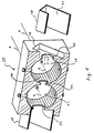
- FIG. 4 A sectioned view of the filter 30 is shown in FIG. 4.
- the filter 30 has two electrically conductive cylindrical resonator cavities, 38, 42, with a common center wall 40.
- Microwave energy traveling through the incoming waveguide 48 enters the first cavity 38 of the filter 30 through an input coupling aperture 50.
- the input coupling aperture 50 is generally elliptical in shape because the coupling factors from rectangular waveguides 48, 49 are different for the TE and TM modes in the cavities.
- the major axis M of the elliptical coupling aperture 50 is perpendicular to the cylindrical resonator axis R, and the minor axis N of the coupling aperture 50 is parallel to the cylindrical resonator axis R.
- microwave energy passes from the first cavity 38 to the second cavity 42 (and then to the next cavity in an "n" section filter) through an inter-stage aperture 44 that is disposed in the common wall(s) 40.
- the inter-stage aperture 44 is also generally elliptical, having a major axis perpendicular to the cylindrical resonator axis R, and the minor axis parallel to the cylindrical resonator axis R for identical frequency responses for the two pass bands.
- Microwave energy exits the second cavity, or the last cavity in an "n" section filter, and enters the outgoing waveguide 49 through the output coupling aperture 52.
- the output coupling aperture 52 is also generally elliptical in shape, and is generally the same as the input coupling aperture 50.
- circular input and output apertures 50, 52 can be used, when identical frequency responses are desired, if the orientation of the input and output waveguides 48, 49 is properly selected. If the broad wall 47 of the wave guide 48 is perpendicular to the axis R of the cylindrical resonator cavities 38, 42, then only the TM mode is excited in the resonator. If the broad wall 47 of the waveguide 48 is parallel to the axis R of the cylindrical resonator cavities 38, 42, then only the TE mode is excited in the resonator.
- the interstage aperture(s) 44 must always be elliptical. It is also noted that other aperture shapes, such as crossed slots, may be used, and that these apertures do not have to be elliptical or circular.
- the filter 30 of Fig. 3 utilizes a recessed waveguide port 46 for accepting the incoming and outgoing waveguides 48, 49. It will be understood that the use of a recessed port is not necessary for the operation of the filter 30. As such, the filter 30 may include flange connections or any other known means for coupling a filter to a guided wave structure.
- the filter 30 contains the two resonator cavities 38, 42, wherein each of the cavities has an internal diameter D, a length L, and a midpoint line P.
- Tuning plungers 54, 56 are spaced at approximately 90 degree intervals around the midpoint P of each cavity 38, 42. As is well known in the art, tuning plungers 54, 56 enable the adjustment of the resonant frequencies within the cavities 38, 42.
- the filter 30 consists of two cavities 38, 42. However, it will be understood that the use of two cavities is exemplary and any number of resonant cavities may be used within the filter 30.
- the dual bandpass response of the filter 30 is achieved by utilizing the TE 1,1,1 and TM 0,1,0 modes in the right circular cylindrical cavities 38, 42. These modes are orthogonal and do not couple to each other, thus there is no power transfer from one mode to the other mode.
- the length L and the diameter D of the cavities 38, 42 determine the frequency response for the filter 30.
- the resonant frequency is determined only by the diameter D of the cavity.
- the resonant frequency of the TM 0,1,0 mode is independent of the cavity length L.
- the resonant frequency of the TE 1,1,1 mode is dependent on both the diameter D and the length L of the cavity.
- FIGs. 5 and 6 illustrates that input coupling aperture 50 and the output coupling aperture 52 are located centrally within the input end 34 and output end 36 of the filter 30, respectively.
- the interstage aperture 44 is positioned in approximately the middle of the center wall 40.
- the tuning plungers 54, 56 are positioned at approximately 90 degree intervals about the mid-point P of each cavity.
- the two tuning plungers 54 in each cavity 38, 42 are located diametrically across from one another to provide a tuning adjustment for one of the modes, which in this case is the TE mode.
- the other tuning plungers 56 of each cavity 38, 42 are symmetrically located in the center of the end caps of the circular cavities 38, 42.
- This set of tuning plungers 56 adjusts the TM mode frequency.
- the tuning plungers 54, 56 allow for trimming the resonant frequencies of each mode of each cavity. This, or some other type of tuning mechanism is necessary for most practical narrow band microwave filters in order to accommodate manufacturing tolerances.
- FIG. 6 there is shown a sectional view through the input end 34 of the dual bandpass microwave filter 30 according to the present invention.
- the ratio of the coupling apertures 50, 52 to the interstage apertures 44 is determined by the desired bandpass ripple of the filter. While the filter 30 is shown with elliptical apertures, it will be understood that other shaped apertures may be included to produce like filtering characteristics.
- RF energy which is transmitted through the waveguide 48 will enter the filter 30 through the input coupling aperture 50.
- the RF energy then enters the first cavity 38 which resonates in two independent orthogonal modes.
- the two cavities 38, 42 are coupled together to provide a desired filtering capacity.
- the intercavity coupling is provided by the interstage aperture 44 which transfers energy between identical modes in the coupled cavities 38, 42.
- Orientation of the waveguide 48 at the input end 34 of the filter is critical for the dual mode operation.
- Orienting the broad wall 47 of the waveguide at an angle ⁇ (0 ⁇ 90°) with respect to the axis R of the cylindrical resonator cavities 38, 42, both the TE and TM modes will be excited in the resonator.
- the two modes are uncoupled and so the electric and magnetic fields are orthogonal at all points within the cavities. Uncoupled modes have no transfer of power from one mode to another within the cavity. In this way, two independent passbands can be established within the filter 30.
- the filtered RF energy will exit the second cavity 42 through the output coupling aperture 52.
- the filtered energy will then be transferred into an outgoing waveguide structure 49.
- the outgoing waveguide 49 will be oriented in line with the incoming waveguide 48 in order to receive energy from both of the excited modes.
- the two resonant frequencies will be determined by the length L and diameter D of the cavities 38, 42. Additional cavity sections can be added to the basic design of the filter 30 in order to further refine and modify the passbands for the two resonant frequencies.
- the dual bandpass microwave filter is especially useful for filtering two frequencies which are generated from a single source.
- the capability to produce two passbands from a single structure reduces the cost and effort of manufacturing.
- Such a design eliminates the critical path lengths which were required in conventionally designed multi-passband filters.
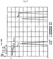
- FIG. 7 shows the frequency response of a single resonator cavity in the 2.7-2.8 GHz range for the individual modes as well as the dual mode response.
- Waves A and B illustrate the frequency response for the TE 1,1,1 and TM 0,1,0 modes, respectively.
- the frequency responses of waves A and B were produced by orienting the waveguide 48 so that only the respective individual modes were excited.
- the response of wave A resulted when the broad wall 47 of the waveguide 48 was parallel to the axis R of the resonator cavity 38, so that only the TE 1,1,1 mode is excited.
- a single passband is located at approximately 2.724GHz.
- the response of wave B resulted when the broad wall 47 of the waveguide 48 was perpendicular to the axis R of the resonator so that only the TM 0,1,0 mode is excited.
- Wave B shows a passband centered at approximately 2.787GHz.
- the frequency response of wave C was produced by orienting the broad wall 47 of the waveguide 48 at a 45 degree angle in order to cause the dual mode excitation.
- the two passbands in the dual mode response are located at approximately 2.725GHz and 2.788GHz.
- FIG 8 is a graph of the response of the two section dual mode filter 30, wherein the waveguides 48, 49 were oriented at an angle ⁇ of 45°, and circular coupling apertures 50, 52 were employed.
- the bandwidth of the TE mode was greater than the bandwidth of the TM mode.
- Equal bandwidths can be obtained through the use of elliptical apertures.
- Steeper skirts can be obtained by using additional dual mode filter sections.
- FIGs. 3-6 employs right circular cylindrical cavities 38, 42 for resonating the TE 1,1,1 and TM 0,1,0 modes
- rectangular or other shaped cavities can be used with equivalent modes, for example the TE 1,0,1 and TM 1,1,1 modes in square waveguide.
- the dual bandpass microwave filters described herein may be fabricated from highly conductive metallic materials. The actual material used depends upon the temperature sensitivity of the device and the system in which it will be employed. Commonly used materials used in fabrication include brass, aluminum, and Invar.
- the present invention discloses a dual mode passband microwave filter which is capable of filtering two resonant frequencies in a desired frequency band.
- the device uses dual modes in a single structure resonator to produce the two passbands.
- the cavity loaded Qs are independently adjustable, so the two pass bands can have the same or different bandwidths, the same of different amplitude ripples, and the same or different phase responses.
Landscapes
- Control Of Motors That Do Not Use Commutators (AREA)
Abstract
A two port dual bandpass microwave filter (30) consisting of "n" resonant cavities (38,42). Each cavity resonates in two independent modes at displaced frequencies so that the filter has two passbands in a desired frequency band. By orienting an incoming waveguide (48) at an angle with respect to the filter, both TE and TM modes can be excited to produce two separate passbands. The passbands may have either equal or unequal characteristics. Fine tuning of the TE and TM modes is accomplished using tuning plungers or tuning screws. The dual bandpass response of the new filter is achieved by utilizing the TE <sub>1,1,1</sub> and TM <sub>0,1,0</sub> modes in right circular cylindrical cavities, or equivalent modes in rectangular, or other cavities. These modes are orthogonal so they do not couple to each other. The cavity loaded Qs are independently adjustable, so the two passbands can have the same or different bandwidths, the same or different amplitude ripples and the same or different phase responses. The dual bandpass microwave filter provides filtering with but one set of cavity resonators rather than two. It does not require three port microwave junctions with critical path lengths. The filter is well-suited to filter the output of a single transmitter capable of operation at two differential frequencies.
Description
- The present invention generally relates to waveguide filters of the type using dual mode cavities, and more particularly to filters which produce dual bandpass transfer functions with a single set of resonant cavities.
- An electrical filter is a two-port circuit that has a desired specified response to a given input signal. Many filters are used to allow certain frequencies to be transmitted to an output load while rejecting the remaining frequencies. The use of low pass, high pass and bandpass filters in microwave systems is well-known to separate frequency components of a complex wave. For instance, microwave filters are commonly used in transmit paths to suppress spurious radiation or in the receive paths to suppress spurious interference.
- The design of microwave filter circuitry is complicated by the fact that conventional electronic components do not retain their basic electric properties when operated at microwave frequencies. Thus, specialized electric circuit techniques which exploit both the electric and magnetic properties of the wave are commonly employed. For example, the conductors which carry microwave signals between components often take the form of waveguides. Waveguides are guided field structures commonly having either rectangular or circular cross sections, usually constructed of a highly conductive material and to a high degree of precision. The effects of capacitance and inductance are introduced into guided field structures through which the microwave signals pass by sitting posts, stubs, annuli and so on. The physical dimensions of these devices and their position in relation to the guided field structure determine the type of effect they are to produce. One such effect would be the passage of only a desired microwave signal band through the waveguide to realize a bandpass filter.
- Waveguide filters may operate in a single mode or may be of a multi-mode type. With the multi-mode filters of previous designs, the existing modes are synchronously tuned to augment the performance of filters with a single passband. Two of the earliest descriptions of a two mode filter is set forth in an article by Ragan, entitled "Microwave Transmission Circuits", Volume 9 of the Radiation Laboratory Series, McGraw Hill, 1948, pp 673-679, and an article by Wei-guan Lin, entitled "Microwave Filters Employing a Single Cavity Excited in more than One Mode", Journal of Applied Physics, Vol. 22, No. 8, August 1951, pp. 989-1001, wherein a five mode single cavity filter is described.
- Many other articles about multi-mode filters, with a single passband, have appeared in the literature, including: "Nonminimum-Phase Optimum-Amplitude Bandpass Waveguide Filters", A.E. Atia and A.E. Williams, IEEE Transactions on Microwave Theory and Techniques, Vol. MTT-22, No. 4, April 1974, pp. 425-431; "Mixed Mode Filters", D.A. Taggart and R.D. Wanselow, IEEE Transactions on Microwave Theory and Techniques, Vol. MTT-22, No. 10, October 1974, pp. 898-902; "Dual Mode Canonical Waveguide Filters", A.E. Williams and A.E. Atia, IEEE Transactions on Microwave Theory and Techniques, Vol. MTT-25, No. 12, December 1977, pp. 1021-1026; and "Filter Design Using In-Line Triple-Mode Cavities and Novel Iris Couplings", U. Rosenberg and D. Wolk, IEEE Transactions on Microwave Theory and Techniques, Vol. MTT-37, No. 12, December 1989, pp. 2011-2019.
- All of the filters described above have the common characteristic of having a single passband. Such filters are useful to filter the output of a transmitter which outputs a single frequency, however, when these filters are employed with transmitters that generate more than one frequency, the design becomes more complicated.
- Referring to Fig. 1, there is shown a conventional prior art two
frequency system 10 that employs twotransmitters port diplexer 20 to combine their outputs. Thefirst transmitter 12 is coupled to thefirst filter 16 via microwave path D and thesecond transmitter 14 is coupled to thesecond filter 18 via microwave path C. The microwave paths will most likely be in the form of waveguides, which as discussed, are well-known in the art. Thefirst filter 16 is coupled to one input of thediplexer 20 via microwave path A and thesecond filter 18 is coupled to the other input of thediplexer 20 via microwave path B. The lengths of the microwave paths C, D which couple thetransmitters respective filters transmitters filters diplexer 20 are critical. That is, exact phase lengths of the paths A, B must be established and maintained for proper operation of thesystem 10. If the operating frequencies of either, or bothtransmitters - When two frequencies are generated by a common source, the design of an output filter system using conventional techniques is more complex than a single frequency system. Referring to Fig. 2, there is shown prior art of an
output filter system 22 which receives two frequencies of microwave signals generated from a common source (not shown). As can be seen, thefilter system 22 employs two threeport junctions first filter 26 and thesecond filter 28. Thefilter system 22 of Fig. 2 contains four critical length microwave paths E, F, G, H. Paths E and F connect thefirst filter 26 with the first and second threeport junctions second filter 28 to the respective threeport junctions filter system 22. Thus, if either frequency in thesystem 22 needs to be changed, then two of the four path lengths must be modified. If both frequencies are changed, then, all of the path lengths E, F, G, H will also require modification. - It is therefore an object of the present invention dual passband microwave filter to provide a single structure microwave filter without the critical path lengths that require modification when frequencies are altered.
- It is further objective of the present invention dual bandpass microwave filter to provide a dual bandpass filter that has a simpler structure, reduced size and lower cost structure than comparable prior art filters.
- A microwave bandpass filter used in conjunction with a waveguide, wherein the waveguide travels in a single distinct plane. The filter is selectively oriented with respect to the plane to determine a desired frequency response. The filter includes at least one resonant cavity having at least two independent modes of propagation. Each cavity includes first and second ports for transfer of energy therebetween. Each cavity is dimensioned to resonate in the independent modes at displaced frequencies. The ports are adapted to receive the waveguide at a predetermined angle of inclination in respect to the plane of the waveguide so that two orthogonal modes are excited in the cavities. The cavities include tuning plungers or tuning screws for adjusting the resonant frequencies of the modes.
- The dual bandpass response of the new filter is achieved by utilizing the TE 1,1,1 and TM 0,1,0 modes in right circular cylindrical cavities, or equivalent modes in rectangular, or other cavities. These modes are orthogonal so they do not couple to each other. The cavity loaded Qs are independently adjustable, so the two passbands can have the same or different bandwidths, the same or different amplitude ripples and the same or different phase responses.
- The dual bandpass microwave filter provides filtering with one set of cavity resonators rather than two. It does not require three port microwave junctions with critical path lengths. The filter can be used to filter the outputs of a single transmitter that operates at two different frequencies.
- For a better understanding of the present invention, reference is made to the following description of exemplary embodiment thereof, considered in conjunction with the accompanying drawings, in which:
- FIG. 1
- is a block diagram of a prior art microwave filter system employing three port diplexer to combine the filtered outputs of two transmitters operating at different frequencies;
- FIG. 2
- is generalization of a prior art dual bandpass microwave filter for use with a dual frequency transmitter;
- FIG. 3
- is a perspective view of one preferred embodiment of the present invention dual bandpass microwave filter, wherein a two section filter is shown;
- FIG. 4
- is a sectioned perspective view of the present invention two section dual bandpass microwave filter viewed along section line 3-3;
- FIG. 5
- is a sectioned side plan view of the present invention two section microwave filter;
- FIG. 6
- is a sectional view of the present invention two section microwave filter;
- FIG. 7
- is a graph showing the frequency response of a one section filter in accordance with the present invention. The graph shows the individual response of each mode, as well as the dual mode operation;
- FIG. 8
- is a graph showing the frequency response of a two section filter in accordance with the present invention;
- FIG. 9
- is a graph showing the frequency response of a single dual mode cavity of the two section filter for the TE1,1,1 mode and the TM0,1,0 mode after TM mode tuning.
- FIG. 10
- is a graph showing the frequency response of a single dual mode cavity of the two section filter for the TE1,1,1 mode and the TM0,1,0 mode after TE mode tuning.
- Referring to FIG. 3, there is shown one preferred embodiment of a dual
passband microwave filter 30 according to the present invention. Thefilter 30 generally comprises aresonator housing 32 having aninput end 34 and anoutput end 36. - A
waveguide 48 is coupled to thefilter 30. Although thewaveguide 48 can be any guided field structure, in the shown embodiment thewaveguide 48 is a rectangular waveguide. Awaveguide port 46 is disposed on theinput end 34 of thefilter 30. Thewaveguide port 46 interconnects with theincoming waveguide 48, thereby joining thefilter 30 to the waveguide structure. Similarly, another waveguide port (not shown) is disposed on theoutput end 36 of thefilter 30, wherein the wave guide port interconnects thefilter 30 with theoutgoing waveguide 49. The wave guides 48 and 49 are oriented at an angle relative to the body of thefilter 30, so the dominant waveguide mode will couple to both the TE and TM modes in the resonators. While a twosection filter 30 is shown, it will be understood that thefilter 30 of Fig. 3 is representative of an "n" section filter, wherein "n" is any positive integer and is determined by the performance of the filter. - A sectioned view of the
filter 30 is shown in FIG. 4. In the shown embodiment, thefilter 30 has two electrically conductive cylindrical resonator cavities, 38, 42, with acommon center wall 40. Microwave energy traveling through theincoming waveguide 48 enters thefirst cavity 38 of thefilter 30 through aninput coupling aperture 50. Theinput coupling aperture 50 is generally elliptical in shape because the coupling factors fromrectangular waveguides elliptical coupling aperture 50 is perpendicular to the cylindrical resonator axis R, and the minor axis N of thecoupling aperture 50 is parallel to the cylindrical resonator axis R. Within thefilter 30, microwave energy passes from thefirst cavity 38 to the second cavity 42 (and then to the next cavity in an "n" section filter) through aninter-stage aperture 44 that is disposed in the common wall(s) 40. Theinter-stage aperture 44 is also generally elliptical, having a major axis perpendicular to the cylindrical resonator axis R, and the minor axis parallel to the cylindrical resonator axis R for identical frequency responses for the two pass bands. Microwave energy exits the second cavity, or the last cavity in an "n" section filter, and enters theoutgoing waveguide 49 through theoutput coupling aperture 52. Theoutput coupling aperture 52 is also generally elliptical in shape, and is generally the same as theinput coupling aperture 50. - It is noted that circular input and
output apertures output waveguides broad wall 47 of thewave guide 48 is perpendicular to the axis R of thecylindrical resonator cavities broad wall 47 of thewaveguide 48 is parallel to the axis R of thecylindrical resonator cavities - The
filter 30 of Fig. 3 utilizes a recessedwaveguide port 46 for accepting the incoming andoutgoing waveguides filter 30. As such, thefilter 30 may include flange connections or any other known means for coupling a filter to a guided wave structure. - Referring to Figs. 5 and 6 in conjunction with Fig. 4, it can be seen that the
filter 30 contains the tworesonator cavities P. Tuning plungers cavity plungers cavities filter 30 consists of twocavities filter 30. The dual bandpass response of thefilter 30 is achieved by utilizing the TE1,1,1 and TM0,1,0 modes in the right circularcylindrical cavities - The length L and the diameter D of the
cavities filter 30. For the TM0,1,0 mode, the resonant frequency is determined only by the diameter D of the cavity. In other words, the resonant frequency of the TM0,1,0 mode is independent of the cavity length L. On the other hand, the resonant frequency of the TE1,1,1 mode is dependent on both the diameter D and the length L of the cavity. When fabricating thedual bandpass filter 30, the cavity diameter D is selected so that the TM0,1,0 mode resonates at one of the desired frequencies. The length L of the cavity is then determined by the second desired frequency. In this way, thefilter 30 has two passbands in a desired frequency band. Selection of the dimensions for the diameter D and the length L, in order to achieve a desired resonant frequency, would be well known to an individual who is skilled in the art of microwave filter design. In order to utilize the TM0,1,0 and the TE1,1,1 modes so that no other modes will be present within the filter, the length L and diameter D must be appropriately chosen. It will be understood that while only two independent modes are present in the described embodiment, that other dimensional variations in the resonant cavities may produce additional modes. - FIGs. 5 and 6 illustrates that
input coupling aperture 50 and theoutput coupling aperture 52 are located centrally within theinput end 34 and output end 36 of thefilter 30, respectively. Similarly, theinterstage aperture 44 is positioned in approximately the middle of thecenter wall 40. Also it can be clearly seen that the tuningplungers tuning plungers 54 in eachcavity other tuning plungers 56 of eachcavity circular cavities plungers 56 adjusts the TM mode frequency. Thus, the tuningplungers - Referring to FIG. 6, there is shown a sectional view through the
input end 34 of the dualbandpass microwave filter 30 according to the present invention. The figure depicts the orientation of thewaveguide port 46 at ϑ=45° from the axis R of thecylindrical cavity 38, and theelliptical input aperture 50 and the ellipticalinter stage aperture 44 required to produce equal loaded Qs for both frequencies. The ratio of thecoupling apertures interstage apertures 44 is determined by the desired bandpass ripple of the filter. While thefilter 30 is shown with elliptical apertures, it will be understood that other shaped apertures may be included to produce like filtering characteristics. - Referring to FIGs. 3-6 in conjunction with one another, one can see that RF energy which is transmitted through the
waveguide 48 will enter thefilter 30 through theinput coupling aperture 50. The RF energy then enters thefirst cavity 38 which resonates in two independent orthogonal modes. The twocavities interstage aperture 44 which transfers energy between identical modes in the coupledcavities - Orientation of the
waveguide 48 at theinput end 34 of the filter is critical for the dual mode operation. By orienting thebroad wall 47 of the waveguide at an angle ϑ (0<ϑ<90°) with respect to the axis R of thecylindrical resonator cavities filter 30, the two modes are uncoupled and so the electric and magnetic fields are orthogonal at all points within the cavities. Uncoupled modes have no transfer of power from one mode to another within the cavity. In this way, two independent passbands can be established within thefilter 30. The filtered RF energy will exit thesecond cavity 42 through theoutput coupling aperture 52. The filtered energy will then be transferred into anoutgoing waveguide structure 49. Theoutgoing waveguide 49 will be oriented in line with theincoming waveguide 48 in order to receive energy from both of the excited modes. As mentioned previously, the two resonant frequencies will be determined by the length L and diameter D of thecavities filter 30 in order to further refine and modify the passbands for the two resonant frequencies. - The dual bandpass microwave filter is especially useful for filtering two frequencies which are generated from a single source. The capability to produce two passbands from a single structure reduces the cost and effort of manufacturing. Such a design eliminates the critical path lengths which were required in conventionally designed multi-passband filters.
- The performance of a dual bandpass filter has been demonstrated using an S-band resonator that was fabricated to mate with a WR284 waveguide. FIG. 7 shows the frequency response of a single resonator cavity in the 2.7-2.8 GHz range for the individual modes as well as the dual mode response. Waves A and B illustrate the frequency response for the TE1,1,1 and TM0,1,0 modes, respectively. The frequency responses of waves A and B were produced by orienting the
waveguide 48 so that only the respective individual modes were excited. The response of wave A resulted when thebroad wall 47 of thewaveguide 48 was parallel to the axis R of theresonator cavity 38, so that only the TE1,1,1 mode is excited. Here, a single passband is located at approximately 2.724GHz. The response of wave B resulted when thebroad wall 47 of thewaveguide 48 was perpendicular to the axis R of the resonator so that only the TM0,1,0 mode is excited. Wave B shows a passband centered at approximately 2.787GHz. The frequency response of wave C was produced by orienting thebroad wall 47 of thewaveguide 48 at a 45 degree angle in order to cause the dual mode excitation. One can see that the two passbands in the dual mode response are located at approximately 2.725GHz and 2.788GHz. - The performance of the
dual mode filter 30 is also demonstrated in Figure 8, which is a graph of the response of the two sectiondual mode filter 30, wherein thewaveguides circular coupling apertures - Most practical narrow band filters need some method of trimming the resonant frequency to accommodate manufacturing tolerances. In the
dual mode filter 30 as described, nearly independent frequency adjustment can be realized with tuningplungers markers plunger 56. This tuning adjustment of the TM mode, as can be seen frommarker 2, causes only a 1MHz variation in the TE mode. Figure 10 illustrates similar independent tuning characteristics for the TE mode usingtuning plungers 54. As can be seen frommarker 1, the TE mode resonant frequency can be lowered by 12MHz while the resonant frequency of the TM mode, as seen frommarker 2 is only increased by 1MHz. - While the
filter 30 described in FIGs. 3-6 employs right circularcylindrical cavities - The dual bandpass microwave filters described herein may be fabricated from highly conductive metallic materials. The actual material used depends upon the temperature sensitivity of the device and the system in which it will be employed. Commonly used materials used in fabrication include brass, aluminum, and Invar.
- Thus, the present invention discloses a dual mode passband microwave filter which is capable of filtering two resonant frequencies in a desired frequency band. The device uses dual modes in a single structure resonator to produce the two passbands. The cavity loaded Qs are independently adjustable, so the two pass bands can have the same or different bandwidths, the same of different amplitude ripples, and the same or different phase responses. By using a single structure to achieve such filtering, the manufacturing efforts and associated costs are greatly reduced. The new filter design eliminates many of the critical microwave paths associated with conventional designs, which were required to have exact phase lengths.
- It will be understood that the embodiments described herein are merely exemplary and that a person skilled in the art may make many variations and modifications to the described embodiment utilizing functionally equivalent components, dimensions and materials. More specifically, it should be understood that various shaped resonator cavities and various shaped waveguides may be used in conjunction with one another. Similarly, the coupling apertures will be shaped in accordance with bandwidth and mode requirements. All such variations and modifications are intended to be included within the scope of this invention as defined by the appended claims.
Claims (20)
- A microwave passband filter having first and second passbands, said filter comprising:
input and output waveguide means for propagating a band of microwave frequencies; and
filter means coupled to said input and output waveguide means, said filter means resonating at a first microwave frequency in a first electromagnetic mode and a second microwave frequency in a second electromagnetic mode, said first and second filter passbands determined by said first and second resonant frequencies, whereby only those frequencies within said filter passbands can propagate within said output waveguide. - The filter of Claim 1, wherein said first electromagnetic mode is a transverse electric (TE) mode and said second electromagnetic mode is a transverse magnetic (TM) mode.
- The filter of Claim 2, wherein said filter means and said waveguide means are disposed about a common longitudinal axis, said waveguide means being oriented about said longitudinal axis at an angle of inclination with respect to said filter means, thereby producing coupling variations to said first and second microwave frequencies.
- The filter of Claim 3, wherein said angle of inclination of said waveguide means is chosen to excite both said TE mode and said TM mode.
- The filter of Claim 4, wherein said angle of inclination is 45 degrees.
- The filter of Claim 1, wherein said filter includes at least one resonant cavity capable of supporting orthogonal electromagnetic modes.
- The filter of Claim 6, wherein each said resonant cavity includes a first port and a second port for transfer of energy into and out of said cavity.
- The filter of Claim 6, including a plurality of resonant cavities, wherein each of said cavities resonates in two orthogonal modes to produce two pass bands within a specified frequency band.
- The filter of Claim 8, wherein each said mode in said resonant cavities is separately adjustable to adjust said first microwave frequency and said second microwave frequency.
- The filter of Claim 9, including tuning means to separately adjust said first and second microwave frequency in each said resonant cavity.
- The filter of Claim 2, wherein said TE mode is a TE1,1,1 mode and said TM mode is a TM0,1,0 mode in a cylindrical cavity.
- The filter of Claim 2, wherein said TE mode is a TE1,0,1 mode and said TM mode is a TM1,1,1 mode in cavity of predetermined shape.
- The filter of Claim 8, wherein each said resonant cavity has a quality factor (Q) associated therewith, said Q of each said resonant cavity being independently adjustable.
- The filter of Claim 1, wherein said filter is an S-band microwave filter.
- The filter of Claim 6, wherein each said cavity is dimensioned to resonate at said first microwave frequency and said second microwave frequency.
- A dual passband microwave filter comprising:
input and output waveguide means; and
filter means coupled to said waveguide means, said filter means including a plurality of resonating cavities disposed therein, each of said cavities resonating at first and second microwave frequencies in orthogonal TE and TM modes respectively, said waveguide means being oriented at an angle of inclination relative said filter means in order to excite said TE and TM modes, and said cavities being tunable to said first and second microwave frequencies to produce a first passband at said first microwave frequency and a second passband at said second microwave frequency. - The filter of Claim 16, wherein said cavities are dimensioned and shaped to resonate at said first and second microwave frequencies.
- The filter of Claim 16, wherein each said mode in said resonant cavities is separately tunable to adjust said first and second microwave frequencies.
- The filter of Claim 16, wherein the RF energy associated with each of said TE and TM modes is substantially equal.
- A microwave passband filter having separate filter passbands, said filter comprising:
input and output waveguide means for propagating a band of microwave frequencies; and
filter means coupled to said input and output waveguide means, said filter means resonating at a first microwave frequency in a first electromagnetic mode and a second microwave frequency in a second electromagnetic mode, said first and second filter passbands determined by said first and second resonant frequencies, whereby only those frequencies within said filter passbands can propagate within said output waveguide, said filter means and said waveguide means being disposed about a common longitudinal axis, and said waveguide means being oriented about said longitudinal axis at an angle of inclination with respect to said filter means, thereby producing coupling variations to said first and second microwave frequencies.
Applications Claiming Priority (2)
| Application Number | Priority Date | Filing Date | Title |
|---|---|---|---|
| US44409 | 1987-04-30 | ||
| US08/044,409 US5349316A (en) | 1993-04-08 | 1993-04-08 | Dual bandpass microwave filter |
Publications (1)
| Publication Number | Publication Date |
|---|---|
| EP0619617A1 true EP0619617A1 (en) | 1994-10-12 |
Family
ID=21932233
Family Applications (1)
| Application Number | Title | Priority Date | Filing Date |
|---|---|---|---|
| EP94104830A Withdrawn EP0619617A1 (en) | 1993-04-08 | 1994-03-26 | Dual bandpass microwave filter |
Country Status (2)
| Country | Link |
|---|---|
| US (1) | US5349316A (en) |
| EP (1) | EP0619617A1 (en) |
Families Citing this family (16)
| Publication number | Priority date | Publication date | Assignee | Title |
|---|---|---|---|---|
| IL105184A (en) * | 1993-03-28 | 1997-01-10 | Sorin Costiner | Microwave selective device for separating a plurality of close frequency bands |
| IT1266852B1 (en) * | 1994-06-08 | 1997-01-21 | Cselt Centro Studi Lab Telecom | BIMODAL CAVITY FOR BANDWAVE FILTERS IN WAVE GUIDE. |
| US5656778A (en) * | 1995-04-24 | 1997-08-12 | Kearfott Guidance And Navigation Corporation | Micromachined acceleration and coriolis sensor |
| ES2109184B1 (en) * | 1995-12-29 | 1998-07-01 | Alcatel Espacio Sa | BIMODE CAVITY FILTER. |
| FR2749107B1 (en) * | 1996-05-22 | 1998-08-21 | Europ Agence Spatiale | BIMODE FILTER WITH CIRCULAR WAVEGUIDE |
| US5909159A (en) * | 1996-09-19 | 1999-06-01 | Illinois Superconductor Corp. | Aperture for coupling in an electromagnetic filter |
| US6032531A (en) * | 1997-08-04 | 2000-03-07 | Kearfott Guidance & Navigation Corporation | Micromachined acceleration and coriolis sensor |
| US6459346B1 (en) * | 2000-08-29 | 2002-10-01 | Com Dev Limited | Side-coupled microwave filter with circumferentially-spaced irises |
| US6898419B1 (en) | 2001-04-30 | 2005-05-24 | Nortel Networks Corporation | Remotely adjustable bandpass filter |
| TWI239116B (en) | 2004-09-01 | 2005-09-01 | Ind Tech Res Inst | Dual-band bandpass filter |
| WO2006026826A1 (en) * | 2004-09-09 | 2006-03-16 | Filtronic Pty Ltd | Multiband filter |
| CN101485040B (en) * | 2006-07-13 | 2014-05-07 | 艾利森电话股份有限公司 | Trimming of waveguide filters |
| CN101853768B (en) * | 2010-04-09 | 2012-07-04 | 长飞光纤光缆有限公司 | Cylindrical plasma resonant cavity |
| GB201608991D0 (en) * | 2016-05-23 | 2016-07-06 | Radio Design Ltd | Mult-band filter apparatus and method of use thereof |
| US10205209B2 (en) * | 2016-11-04 | 2019-02-12 | Com Dev Ltd. | Multi-band bandpass filter |
| US10903540B2 (en) * | 2019-05-31 | 2021-01-26 | Nokia Solutions And Networks Oy | Dual-mode corrugated waveguide cavity filter |
Citations (4)
| Publication number | Priority date | Publication date | Assignee | Title |
|---|---|---|---|---|
| US2337184A (en) * | 1941-01-10 | 1943-12-21 | Rca Corp | Coupling circuit |
| US2770778A (en) * | 1951-04-27 | 1956-11-13 | Rca Corp | Slot coupling for tangent circular waveguide structures |
| JPS5767301A (en) * | 1980-10-15 | 1982-04-23 | Nippon Telegr & Teleph Corp <Ntt> | Feeding device for circular polarized wave |
| DE4014541A1 (en) * | 1990-05-07 | 1991-11-14 | Ant Nachrichtentech | Microwave filter with cavity resonator(s) - has input and output coupling for simultaneous handling of several resonance modes |
Family Cites Families (3)
| Publication number | Priority date | Publication date | Assignee | Title |
|---|---|---|---|---|
| US2890421A (en) * | 1953-02-26 | 1959-06-09 | Univ California | Microwave cavity filter |
| US3697898A (en) * | 1970-05-08 | 1972-10-10 | Communications Satellite Corp | Plural cavity bandpass waveguide filter |
| US5012211A (en) * | 1987-09-02 | 1991-04-30 | Hughes Aircraft Company | Low-loss wide-band microwave filter |
-
1993
- 1993-04-08 US US08/044,409 patent/US5349316A/en not_active Expired - Lifetime
-
1994
- 1994-03-26 EP EP94104830A patent/EP0619617A1/en not_active Withdrawn
Patent Citations (4)
| Publication number | Priority date | Publication date | Assignee | Title |
|---|---|---|---|---|
| US2337184A (en) * | 1941-01-10 | 1943-12-21 | Rca Corp | Coupling circuit |
| US2770778A (en) * | 1951-04-27 | 1956-11-13 | Rca Corp | Slot coupling for tangent circular waveguide structures |
| JPS5767301A (en) * | 1980-10-15 | 1982-04-23 | Nippon Telegr & Teleph Corp <Ntt> | Feeding device for circular polarized wave |
| DE4014541A1 (en) * | 1990-05-07 | 1991-11-14 | Ant Nachrichtentech | Microwave filter with cavity resonator(s) - has input and output coupling for simultaneous handling of several resonance modes |
Non-Patent Citations (4)
| Title |
|---|
| PATENT ABSTRACTS OF JAPAN vol. 6, no. 144 (E - 122) 3 August 1982 (1982-08-03) * |
| S.-L. LAI ET AL.: "TM triple-mode microwave filter", ELECTRONICS LETTERS, vol. 26, no. 25, 6 December 1990 (1990-12-06), STEVENAGE GB, pages 2112 - 2113, XP000177118 * |
| U. ROSENBERG: "Multiplexing and double band filtering with common-multimode cavities", IEEE TRANSACTIONS ON MICROWAVE THEORY AND TECHNIQUES, vol. 38, no. 12, December 1990 (1990-12-01), NEW YORK US, pages 1862 - 1871, XP000168520, DOI: doi:10.1109/22.64567 * |
| W-.C. TANG ET AL.: "A true elliptic-function filter using triple-mode degenerate cavities", IEEE TRANSACTIONS ON MICROWAVE THEORY AND TECHNIQUES, vol. 32, no. 11, November 1984 (1984-11-01), NEW YORK US, pages 1449 - 1454 * |
Also Published As
| Publication number | Publication date |
|---|---|
| US5349316A (en) | 1994-09-20 |
Similar Documents
| Publication | Publication Date | Title |
|---|---|---|
| US3899759A (en) | Electric wave resonators | |
| US5349316A (en) | Dual bandpass microwave filter | |
| US4453146A (en) | Dual-mode dielectric loaded cavity filter with nonadjacent mode couplings | |
| US5083102A (en) | Dual mode dielectric resonator filters without iris | |
| US4477785A (en) | Generalized dielectric resonator filter | |
| US6781487B2 (en) | Multimode dielectric resonator device, dielectric filter, composite dielectric filter, synthesizer, distributor, and communication device | |
| US5172084A (en) | Miniature planar filters based on dual mode resonators of circular symmetry | |
| US20080122559A1 (en) | Microwave Filter Including an End-Wall Coupled Coaxial Resonator | |
| EP0064799A1 (en) | Miniature dual-mode, dielectric-loaded cavity filter | |
| Zaki et al. | Canonical and longitudinal dual-mode dielectric resonator filters without iris | |
| EP1041663A1 (en) | General response dual-mode, dielectric resonator loaded cavity filter | |
| CA1067162A (en) | Generalized waveguide bandpass filters | |
| US5268659A (en) | Coupling for dual-mode resonators and waveguide filter | |
| US20020149449A1 (en) | Quasi dual-mode resonator | |
| Wong et al. | Waveguide components based on multiple-mode resonators: Advances in microwave multiple-mode waveguide components, including multiplexers, three-state diplexers, crossovers, and balanced/unbalanced elements | |
| US4644305A (en) | Odd order elliptic waveguide cavity filters | |
| KR100337165B1 (en) | Dielectric filter, dielectric duplexer, and communication device | |
| US6975181B2 (en) | Dielectric resonator loaded metal cavity filter | |
| US3668564A (en) | Waveguide channel diplexer and mode transducer | |
| US4888569A (en) | Magnetically tuneable millimeter wave bandpass filter having high off resonance isolation | |
| CA1271532A (en) | Microwave filter | |
| EP0605642A4 (en) | Narrow band-pass, wide band-stop filter. | |
| JP2641090B2 (en) | Dual mode cavity resonator for waveguide bandpass filter | |
| US4231001A (en) | Constant resistance coupling network | |
| JPS63232602A (en) | Resonance filter |
Legal Events
| Date | Code | Title | Description |
|---|---|---|---|
| PUAI | Public reference made under article 153(3) epc to a published international application that has entered the european phase |
Free format text: ORIGINAL CODE: 0009012 |
|
| AK | Designated contracting states |
Kind code of ref document: A1 Designated state(s): DE FR GB |
|
| 17P | Request for examination filed |
Effective date: 19950128 |
|
| 17Q | First examination report despatched |
Effective date: 19970414 |
|
| STAA | Information on the status of an ep patent application or granted ep patent |
Free format text: STATUS: THE APPLICATION IS DEEMED TO BE WITHDRAWN |
|
| 18D | Application deemed to be withdrawn |
Effective date: 19970826 |