EP0619404A2 - Roof panel with solar batteries and roof structure with solar batteries - Google Patents
Roof panel with solar batteries and roof structure with solar batteries Download PDFInfo
- Publication number
- EP0619404A2 EP0619404A2 EP94302272A EP94302272A EP0619404A2 EP 0619404 A2 EP0619404 A2 EP 0619404A2 EP 94302272 A EP94302272 A EP 94302272A EP 94302272 A EP94302272 A EP 94302272A EP 0619404 A2 EP0619404 A2 EP 0619404A2
- Authority
- EP
- European Patent Office
- Prior art keywords
- frame
- solar battery
- gutter
- roof
- support rails
- Prior art date
- Legal status (The legal status is an assumption and is not a legal conclusion. Google has not performed a legal analysis and makes no representation as to the accuracy of the status listed.)
- Granted
Links
Images




Classifications
-
- H—ELECTRICITY
- H02—GENERATION; CONVERSION OR DISTRIBUTION OF ELECTRIC POWER
- H02S—GENERATION OF ELECTRIC POWER BY CONVERSION OF INFRARED RADIATION, VISIBLE LIGHT OR ULTRAVIOLET LIGHT, e.g. USING PHOTOVOLTAIC [PV] MODULES
- H02S20/00—Supporting structures for PV modules
- H02S20/20—Supporting structures directly fixed to an immovable object
- H02S20/22—Supporting structures directly fixed to an immovable object specially adapted for buildings
- H02S20/23—Supporting structures directly fixed to an immovable object specially adapted for buildings specially adapted for roof structures
-
- F—MECHANICAL ENGINEERING; LIGHTING; HEATING; WEAPONS; BLASTING
- F24—HEATING; RANGES; VENTILATING
- F24S—SOLAR HEAT COLLECTORS; SOLAR HEAT SYSTEMS
- F24S20/00—Solar heat collectors specially adapted for particular uses or environments
- F24S20/60—Solar heat collectors integrated in fixed constructions, e.g. in buildings
- F24S20/67—Solar heat collectors integrated in fixed constructions, e.g. in buildings in the form of roof constructions
-
- F—MECHANICAL ENGINEERING; LIGHTING; HEATING; WEAPONS; BLASTING
- F24—HEATING; RANGES; VENTILATING
- F24S—SOLAR HEAT COLLECTORS; SOLAR HEAT SYSTEMS
- F24S25/00—Arrangement of stationary mountings or supports for solar heat collector modules
- F24S25/20—Peripheral frames for modules
-
- F—MECHANICAL ENGINEERING; LIGHTING; HEATING; WEAPONS; BLASTING
- F24—HEATING; RANGES; VENTILATING
- F24S—SOLAR HEAT COLLECTORS; SOLAR HEAT SYSTEMS
- F24S25/00—Arrangement of stationary mountings or supports for solar heat collector modules
- F24S25/30—Arrangement of stationary mountings or supports for solar heat collector modules using elongate rigid mounting elements extending substantially along the supporting surface, e.g. for covering buildings with solar heat collectors
- F24S25/33—Arrangement of stationary mountings or supports for solar heat collector modules using elongate rigid mounting elements extending substantially along the supporting surface, e.g. for covering buildings with solar heat collectors forming substantially planar assemblies, e.g. of coplanar or stacked profiles
- F24S25/35—Arrangement of stationary mountings or supports for solar heat collector modules using elongate rigid mounting elements extending substantially along the supporting surface, e.g. for covering buildings with solar heat collectors forming substantially planar assemblies, e.g. of coplanar or stacked profiles by means of profiles with a cross-section defining separate supporting portions for adjacent modules
-
- F—MECHANICAL ENGINEERING; LIGHTING; HEATING; WEAPONS; BLASTING
- F24—HEATING; RANGES; VENTILATING
- F24S—SOLAR HEAT COLLECTORS; SOLAR HEAT SYSTEMS
- F24S25/00—Arrangement of stationary mountings or supports for solar heat collector modules
- F24S25/60—Fixation means, e.g. fasteners, specially adapted for supporting solar heat collector modules
- F24S25/61—Fixation means, e.g. fasteners, specially adapted for supporting solar heat collector modules for fixing to the ground or to building structures
-
- F—MECHANICAL ENGINEERING; LIGHTING; HEATING; WEAPONS; BLASTING
- F24—HEATING; RANGES; VENTILATING
- F24S—SOLAR HEAT COLLECTORS; SOLAR HEAT SYSTEMS
- F24S25/00—Arrangement of stationary mountings or supports for solar heat collector modules
- F24S25/60—Fixation means, e.g. fasteners, specially adapted for supporting solar heat collector modules
- F24S25/67—Fixation means, e.g. fasteners, specially adapted for supporting solar heat collector modules for coupling adjacent modules or their peripheral frames
-
- F—MECHANICAL ENGINEERING; LIGHTING; HEATING; WEAPONS; BLASTING
- F24—HEATING; RANGES; VENTILATING
- F24S—SOLAR HEAT COLLECTORS; SOLAR HEAT SYSTEMS
- F24S40/00—Safety or protection arrangements of solar heat collectors; Preventing malfunction of solar heat collectors
- F24S40/40—Preventing corrosion; Protecting against dirt or contamination
- F24S40/44—Draining rainwater or condensation
-
- H—ELECTRICITY
- H02—GENERATION; CONVERSION OR DISTRIBUTION OF ELECTRIC POWER
- H02S—GENERATION OF ELECTRIC POWER BY CONVERSION OF INFRARED RADIATION, VISIBLE LIGHT OR ULTRAVIOLET LIGHT, e.g. USING PHOTOVOLTAIC [PV] MODULES
- H02S30/00—Structural details of PV modules other than those related to light conversion
- H02S30/10—Frame structures
-
- F—MECHANICAL ENGINEERING; LIGHTING; HEATING; WEAPONS; BLASTING
- F24—HEATING; RANGES; VENTILATING
- F24S—SOLAR HEAT COLLECTORS; SOLAR HEAT SYSTEMS
- F24S20/00—Solar heat collectors specially adapted for particular uses or environments
- F24S2020/10—Solar modules layout; Modular arrangements
- F24S2020/12—Coplanar arrangements with frame overlapping portions
-
- Y—GENERAL TAGGING OF NEW TECHNOLOGICAL DEVELOPMENTS; GENERAL TAGGING OF CROSS-SECTIONAL TECHNOLOGIES SPANNING OVER SEVERAL SECTIONS OF THE IPC; TECHNICAL SUBJECTS COVERED BY FORMER USPC CROSS-REFERENCE ART COLLECTIONS [XRACs] AND DIGESTS
- Y02—TECHNOLOGIES OR APPLICATIONS FOR MITIGATION OR ADAPTATION AGAINST CLIMATE CHANGE
- Y02A—TECHNOLOGIES FOR ADAPTATION TO CLIMATE CHANGE
- Y02A30/00—Adapting or protecting infrastructure or their operation
- Y02A30/60—Planning or developing urban green infrastructure
-
- Y—GENERAL TAGGING OF NEW TECHNOLOGICAL DEVELOPMENTS; GENERAL TAGGING OF CROSS-SECTIONAL TECHNOLOGIES SPANNING OVER SEVERAL SECTIONS OF THE IPC; TECHNICAL SUBJECTS COVERED BY FORMER USPC CROSS-REFERENCE ART COLLECTIONS [XRACs] AND DIGESTS
- Y02—TECHNOLOGIES OR APPLICATIONS FOR MITIGATION OR ADAPTATION AGAINST CLIMATE CHANGE
- Y02B—CLIMATE CHANGE MITIGATION TECHNOLOGIES RELATED TO BUILDINGS, e.g. HOUSING, HOUSE APPLIANCES OR RELATED END-USER APPLICATIONS
- Y02B10/00—Integration of renewable energy sources in buildings
- Y02B10/10—Photovoltaic [PV]
-
- Y—GENERAL TAGGING OF NEW TECHNOLOGICAL DEVELOPMENTS; GENERAL TAGGING OF CROSS-SECTIONAL TECHNOLOGIES SPANNING OVER SEVERAL SECTIONS OF THE IPC; TECHNICAL SUBJECTS COVERED BY FORMER USPC CROSS-REFERENCE ART COLLECTIONS [XRACs] AND DIGESTS
- Y02—TECHNOLOGIES OR APPLICATIONS FOR MITIGATION OR ADAPTATION AGAINST CLIMATE CHANGE
- Y02B—CLIMATE CHANGE MITIGATION TECHNOLOGIES RELATED TO BUILDINGS, e.g. HOUSING, HOUSE APPLIANCES OR RELATED END-USER APPLICATIONS
- Y02B10/00—Integration of renewable energy sources in buildings
- Y02B10/20—Solar thermal
-
- Y—GENERAL TAGGING OF NEW TECHNOLOGICAL DEVELOPMENTS; GENERAL TAGGING OF CROSS-SECTIONAL TECHNOLOGIES SPANNING OVER SEVERAL SECTIONS OF THE IPC; TECHNICAL SUBJECTS COVERED BY FORMER USPC CROSS-REFERENCE ART COLLECTIONS [XRACs] AND DIGESTS
- Y02—TECHNOLOGIES OR APPLICATIONS FOR MITIGATION OR ADAPTATION AGAINST CLIMATE CHANGE
- Y02E—REDUCTION OF GREENHOUSE GAS [GHG] EMISSIONS, RELATED TO ENERGY GENERATION, TRANSMISSION OR DISTRIBUTION
- Y02E10/00—Energy generation through renewable energy sources
- Y02E10/40—Solar thermal energy, e.g. solar towers
- Y02E10/44—Heat exchange systems
-
- Y—GENERAL TAGGING OF NEW TECHNOLOGICAL DEVELOPMENTS; GENERAL TAGGING OF CROSS-SECTIONAL TECHNOLOGIES SPANNING OVER SEVERAL SECTIONS OF THE IPC; TECHNICAL SUBJECTS COVERED BY FORMER USPC CROSS-REFERENCE ART COLLECTIONS [XRACs] AND DIGESTS
- Y02—TECHNOLOGIES OR APPLICATIONS FOR MITIGATION OR ADAPTATION AGAINST CLIMATE CHANGE
- Y02E—REDUCTION OF GREENHOUSE GAS [GHG] EMISSIONS, RELATED TO ENERGY GENERATION, TRANSMISSION OR DISTRIBUTION
- Y02E10/00—Energy generation through renewable energy sources
- Y02E10/40—Solar thermal energy, e.g. solar towers
- Y02E10/47—Mountings or tracking
-
- Y—GENERAL TAGGING OF NEW TECHNOLOGICAL DEVELOPMENTS; GENERAL TAGGING OF CROSS-SECTIONAL TECHNOLOGIES SPANNING OVER SEVERAL SECTIONS OF THE IPC; TECHNICAL SUBJECTS COVERED BY FORMER USPC CROSS-REFERENCE ART COLLECTIONS [XRACs] AND DIGESTS
- Y02—TECHNOLOGIES OR APPLICATIONS FOR MITIGATION OR ADAPTATION AGAINST CLIMATE CHANGE
- Y02E—REDUCTION OF GREENHOUSE GAS [GHG] EMISSIONS, RELATED TO ENERGY GENERATION, TRANSMISSION OR DISTRIBUTION
- Y02E10/00—Energy generation through renewable energy sources
- Y02E10/50—Photovoltaic [PV] energy
-
- Y—GENERAL TAGGING OF NEW TECHNOLOGICAL DEVELOPMENTS; GENERAL TAGGING OF CROSS-SECTIONAL TECHNOLOGIES SPANNING OVER SEVERAL SECTIONS OF THE IPC; TECHNICAL SUBJECTS COVERED BY FORMER USPC CROSS-REFERENCE ART COLLECTIONS [XRACs] AND DIGESTS
- Y02—TECHNOLOGIES OR APPLICATIONS FOR MITIGATION OR ADAPTATION AGAINST CLIMATE CHANGE
- Y02P—CLIMATE CHANGE MITIGATION TECHNOLOGIES IN THE PRODUCTION OR PROCESSING OF GOODS
- Y02P80/00—Climate change mitigation technologies for sector-wide applications
- Y02P80/20—Climate change mitigation technologies for sector-wide applications using renewable energy
-
- Y—GENERAL TAGGING OF NEW TECHNOLOGICAL DEVELOPMENTS; GENERAL TAGGING OF CROSS-SECTIONAL TECHNOLOGIES SPANNING OVER SEVERAL SECTIONS OF THE IPC; TECHNICAL SUBJECTS COVERED BY FORMER USPC CROSS-REFERENCE ART COLLECTIONS [XRACs] AND DIGESTS
- Y10—TECHNICAL SUBJECTS COVERED BY FORMER USPC
- Y10S—TECHNICAL SUBJECTS COVERED BY FORMER USPC CROSS-REFERENCE ART COLLECTIONS [XRACs] AND DIGESTS
- Y10S136/00—Batteries: thermoelectric and photoelectric
- Y10S136/291—Applications
Definitions
- This invention relates to roof panels with solar batteries and roof structures with solar batteries, these roof panels and structure being capable of application to roof portions of houses and like buildings.
- the general way of installing solar batteries on the roof is a base securement system, in which panel-like solar batteries are secured to an available roof via an exclusive base.
- the present invention has been completed in view of the above circumstances, and its object is to provide a roof panel with solar batteries and a roof structure with solar batteries, which permit improvement of the water blocking between adjacent solar batteries which are made integral with the roof panel.
- the solar batteries that are used are supported with respective frames, which are collectively supported on support rails extending in the direction of roof inclination such that rainwater falling onto the surfaces of the solar batteries and support rails can be led toward the roof eaves for draining.
- rainwater which may enter the space between the solar battery and the frame thereof, the space between each frame and each support rail and the space between adjacent frames, can be received to be drained toward the eaves of the roof.
- a roof panel with solar batteries which comprises a base panel disposed along the roof inclination from the ridge to the eaves and a plurality of solar battery panels disposed over the base panel; the solar battery panels each including a solar battery in the form of a rectangular disk and a frame mounted around the solar battery; a plurality of parallel gutter-like support rails being secured to the upper surface of the base panel such that they extend in the direction of roof inclination; the frames each being supported such as to be accommodated inside associated ones of the support rails.
- the solar battery panels which are arranged in rows extending in the direction of roof inclination are supported via their frames on the support rails which extend in the direction of roof inclination.
- seam portions of adjacent solar batteries which are arranged side by side in the horizontal direction i.e., the direction perpendicular to the direction of roof inclination
- support rails It is thus possible to ensure water blocking without need of any special rainwater blocking structure for the seam portions.
- the support rails are gutter-like, rainwater falling on the support rails can be readily drained.
- each support rail has a two-stage structure including a gutter section capable of accommodating an associated portion of each frame and a cylindrical section formed under and integral with the gutter section; and each frame is supported such that it is accommodated in associated ones of the gutter sections.
- each support rail has a two-stage structure including a gutter section and a cylindrical section
- each frame accommodated in associated gutter sections, rainwater flows through the gutter sections, and if it overflows over the gutter sections, it can be received by the cylindrical sections.
- the frame includes four cylindrical frame members, two of which are an upper and a lower frame member mounted on parallel two of the four edges of the solar battery, and the other two of which are a left and a right vertical frame member mounted on the other two of the four edges; and the left and right vertical frame members are supported such that they are accommodated inside associate gutter-like support rails, at least the inner space in the lower frame member being communicated with the inside of the associated gutter-like support rails.
- the frame has an extension extending from its eves side portion and covering the top of a ridge side portion of the frame of the eaves side adjacent solar battery panel; and the extension has an edge substantially aligned to the eaves side edge of a ridge side portion of the frame of the eaves side adjacent solar battery panel.
- the extension covers the ridge side frame of the eaves side solar battery frame, it is difficult for rainwater to enter between the two solar battery panels.
- a solar battery panel which has improved properties of draining and blocking of water.
- the extension has an edge which is substantially aligned to the eaves side edge of a ridge side portion of the frame of the eaves side adjacent solar battery panel, the eaves side frame portion that is covered by the extension is not exposed at the surface. It is thus possible to obtain improved appearance.
- support rails are provided in pairs each in correspondence to facing sides of adjacent solar battery panels in a direction perpendicular to the direction of roof inclination, a seal member being provided between adjacent side vertical walls of the gutter sections of the paired adjacent support rails, another seal member being provided such that it strides the upper ends of the two adjacent side vertical walls.
- the support rails for supporting the both sides of the solar battery panel may be used those which support only a single side.
- the same support frame may be utilized for the ends of the solar battery panel row (without adjacent solar battery panel in the direction perpendicular to the direction of roof inclination) and also intermediate points (with adjacent solar battery panel) thereof. With this arrangement, it is possible to ensure water blocking between two support rails.
- a predetermined space serving as a ventilating layer is formed between the back surface of each solar panel and the base panel, the ventilating layer being open to the outside at its eaves and ridge side edges.
- Fig. 1 is a sectional view showing an embodiment of the invention applied to the house roof structure extending from the ridge to the eaves.
- reference numeral 1 designates a rectangular roof panel with solar batteries according to the invention.
- the roof panel 1 is disposed such that its longitudinal direction is from the ridge M to the eaves N, and it constitutes a roof Y.
- the roof panel 1 with solar batteries comprises a rectangular base panel 2 with a panel sheet 2b thereof disposed on a plurality of core members 2b assembled in longitudinal and transversal directions and a plurality of solar battery panels 3 provided on the base panel 2.
- Each solar battery panel 3 as shown in Figs. 2 to 5, comprises a rectangular panel-shaped solar battery 4, which has a large number of solar battery cells provided in a transparent plate, grading channel members 5 detachably fitted on the four edges of the solar battery 4, and a frame of the solar battery panel 3, which is detachably mounted around the grading channel members 5 and consists of four frame members, i.e., an upper and lower frame member 6 and 7 and a pair of, i.e., left and right side, vertical frame members 8.
- Each grading channel member 5 is a channel-shaped member, in which an edge of the solar battery 4 is fitted. It is made of a material having a certain elasticity, and it integrally has a substantially flat inner wall portion 9, side wall portions 10 extending from the opposite width direction edges of the inner wall portion 10 substantially at right angles thereto, a head portion 11 having a frust-conical sectional profile and terminating in the side wall portions 10, and a pair of tongue portions integrally extending from the inner surfaces of the side wall portions 10 toward each other (i.e., in the width direction).
- the inner wall portion 9 of the grading channel member 5 has a central engagement notch 5a extending in the longitudinal direction.
- the inner wall portion 9 has ribs 9a extending from its opposite width direction edges and extending slight outward with respect to the side wall portions 10.
- the head portion 11 has ribs lla slightly extending outward from its opposite width direction edges. With these ribs, engagement grooves 5b are formed in the opposite sides (i.e., upper and lower sides in the Figure) of the grading channel member 5 such that they extend in the longitudinal direction thereof.
- the grading channel member 5 is fitted on the solar battery 4 by fitting its engagement notch on the corresponding edge of the solar battery 4 until the edge thereof is in contact with the inner surface of the head portion 11. In this state, the surfaces of the inner wall portion 9 defining the engagement notch 5a is held pushed against and in close contact with the edge of the solar battery 4. In addition, the tongues 12 are elastically deformed by the inserted edge of the solar battery 4, and their edges are in close contact with the solar battery edge.
- the frame members 6 to 8 are mounted on the grading channel members 5 fitted on the edges of the solar battery 4 and form a frame thereof.
- These frame members are of three different kinds, i.e., the upper and lower frame members 6 and 7 which are mounted on opposite sides of the solar battery 4 and the vertical frame members 8 mounted on the other opposite sides.
- the solar battery 3 is disposed such that the upper frame member 6 is directed toward the ridge M, the lower frame member 7 is directed toward the eaves N and the vertical frame members 8 extend in the direction of inclination of the roof Y.
- These frame members 6 to 8 my be fabricated by extrusion molding aluminum or the like.
- the upper and lower frame members 6 and 7, as shown in Fig. 2, have basically the same structure.
- the inner wall 14 has an opening 18 which extends in the longitudinal direction.
- the frame member is cylindrical having a substantially rectangular sectional profile, with an outside cavity 19 defined by the outer, inner, upper and lower walls 13 to 16.
- the lower wall 16 has an integral projection 20 extending perpendicularly from its edge toward the upper wall 15.
- the edge of the inner wall 14 adjacent the opening 18 has a short engagement projection 21, which extends toward the partitioning wall 17 and is tightly fitted in the corresponding engagement groove 5b of the grading channel member 5.
- the partitioning wall 17 is parallel to the outer and inner walls 13 and 14, and the inner side of the partitioning wall 17, i.e., the inner surface thereof facing the outer wall 13, has an integral bolt hole piece 22.
- the edge thereof on the side of the opening 18 is formed with a rectangular notch 23.
- the upper and lower frame members 6 and 7 are different from each other in that in the upper frame member 6 the outer wall 13 has an integral contact portion 24 having an L-shaped sectional profile, whereas in the lower frame member 7 the lower wall 16 has an integral extension 25 extending outward to a greater extent than that of the upper frame member 6.
- the contact portion 24 extends in the longitudinal direction from the end of the outer wall 13 nearer the lower wall 16. Its end portion is provided with a seal member 22 applied thereto.
- the extension 25 has an inclined portion 25a extending from the upper wall 15 in a slightly upwardly inclined direction and a portion extending from the inclined portion 25a in a direction parallel to the upper wall 15. Its lower surface is set such as to be slightly above the upper surface of the lower wall 16.
- Adjacent solar battery panels 3 are arranged with their upper walls 15 set upward such that the outer wall 13 of the lower one of them abuts the inner wall 14 of the upper one of them via the intervening seal member 26. In this state, the extension 25 of the lower frame member 7 of the upper one of them covers the upper wall 15 of the upper frame member 6 of the lower one of them.
- the extension 25 has a length such that its end coincides with the end of the upper wall 15 of the upper frame member 6 in its state covering the upper wall 15 of the upper frame 6 of the lower solar battery panel 3 as noted above.
- the gap between the two is set such that no rainwater will rise by the capillary phenomenon and enter between the adjacent solar battery panels 3.
- the upper and lower frame members 6 and 7 as noted above, are mounted on the solar battery 4 via the respective grading channel members 5 by disposing the upper wall 15 on the surface side of the solar battery 4, inserting the head portion 11 of each grading channel member 5 in each opening 18 and engaging the upper and lower engagement projections 21 in the respective upper and lower engagement grooves 5b.
- the vertical frame member 8 integrally has an outer and an inner wall 27 and 28, which are parallel and face each other, an upper and a lower wall 29 and 30, which are parallel and face each other, and a securement portion 31 extending outward from the lower edge of the outer wall 27.
- the inner wall 28 has an opening 32 extending in the longitudinal direction.
- the frame member thus is cylindrical in shape having a rectangular sectional profile.
- the lower wall 30 is located on the inner side of the lower edge of the outer and inner walls 27 and 28, and the opening 32 noted above is formed in the inner wall 28 between the lower and upper walls 30 and 29.
- the edge of the inner wall 28 adjacent the opening 32 has a short engagement projection 34, which extends toward the outer wall 27 and is tightly engaged in the corresponding engagement groove 5b of the grading channel member 5.
- Each edge of the inner wall 28 has a rectangular notch 35.
- the vertical frame member 8 as described above, is mounted on the solar battery 4 via the grading channel member 5 by disposing the upper wall 29 on the surface side of the solar battery 4, inserting the head portion 11 of the grading channel 5 in the opening 32 and engaging the upper and lower engagement projections 34 in the upper and lower engagement grooves 5b.
- the opening 32 of the vertical frame member 8 is closed by the head portion 11 of the grading channel member 5, and an upper cavity 33a is formed inside the inner wall 28.
- the opposite ends of the upper and lower frame members 6 and 7 enters the inside of the vertical frame members 8 with the engagement of the notches 23 and 25, and the outer walls 29 of the vertical frame members 8 cover the outer walls 29 of the upper and lower frame members 6 and 7.
- the frame members 6 to 8 are finally mounted on the four edges of the solar battery 4 via the grading channel members 5 by screwing bolts 36, which penetrate the outer walls 27 of the vertical frame members 8, through the bolt hole pieces 22 of the upper and lower frame members 6 and 7. In this way, the solar battery panel 3 is assembled.
- Fig. 4 shows the solar battery panel 3 in its assembled state.
- Fig. 5 shows it in a disassembled state.
- the opposite ends of the upper and lower frame members 6 and 7 are fitted in the inside of the vertical frame members 8 with the engagement of the notches 23 and 35.
- the inner cavities 19b of the upper and lower frame members 6 and 7 and the upper cavities 33a of the vertical frame members 8 are communicated with one another.
- the surfaces of the upper walls 15 and 29 of the frame members 6 to 8 are at a somewhat higher level than the surface of the solar battery 4.
- the surface of the entirety of the solar battery panel 3 has a rectangular recess 4a corresponding to the solar battery 4.
- a plurality of solar battery panels 3, having the construction as described above, are arranged (for instance two panels transversally and five panels longitudinally) over and secured to the upper surface of a face plate 2b of the base panel 2. However, they are not directly secured to the face plate 2b, but are secured to gutter-like support rails 37 which are secured to the face plate 2b.
- the support rail 37 has a vertically two-stage structure, comprising a gutter-like frame 38 having a substantially U-shaped sectional profile and open at the top and a plate-like support 39 formed within the frame 38, the support 30 being common to an upper gutter section 37a and a lower cylindrical section 37b.
- the gutter-like frame 38 has a pair of, i.e., left and right, vertical walls 40.
- one of the vertical walls 40 extends basically substantially upright although it has a slight bent profile 40a formed on the inner side in the width direction and bent in a fashion like a crankshaft profile.
- the other vertical wall 40 is an inclined wall 40b inclined toward the inner side.
- the vertical wall 40 with the bent profile 40a is referred to as outer vertical wall 40A, and that with the inclined portion 40b as inner vertical wall 40B.
- the inclined portion 40b of the inner vertical wall 40B has a longitudinally extending integral securement piece 41 at right angles to the inclined portion 40b. The end of the securement piece 41 is located on the extension of the inner vertical wall 40 in the gutter section 37a.
- These support rails 37 are arranged in pairs of them at a predetermined interval on and secured to the face plate 2b of the base panel 2 with asphalt roofing 42 applied thereto such that their longitudinal direction is in the longitudinal direction of the base panel 2 and that the paired vertical frame members 8 of each solar battery panel 3 are accommodated in their corresponding gutter sections 37a.
- the pair of support rails 37 are parallel such that their inner vertical walls 40B face each other.
- Core members 2a extending in the longitudinal direction of the base panel 2 are secured to the underside of the face plate 2b, on which the support rails 37 are supported.
- the support rails 37 are secured to the base panel 2 by driving wooden bolts 43 passed through the securement pieces 41.
- the asphalt roofing 42 is secured to the face plate 2b by double side adhesive tapes 44, which are applied to portions of the face plate 2b that support the support rails 37.
- All the solar battery panels 3 which are arranged in the longitudinal direction of the base panel 2 are collectively secured to the base panel by the pairs of support rails 37. In each zone where adjacent solar battery panels 3 face each other in the width direction (other than the direction of roof inclination), two support rails 37 are secured in close proximity of each other.
- a plurality of solar battery panels 3 are secured to the paired support rails 37 with their upper frame member 6 on the side of the ridge M, with their lower frame member 7 on the side of the eaves N and with their vertical frame members 8 supported on the supports 39 of the gutter sections 37a.
- each vertical frame member 8 under upper cavity 33a of each vertical frame member 8 is formed lower cavity 33b, which is defined by the outer and inner walls 27 and 28, lower wall 30 and support 38.
- the upper and lower cavities 33a and 33b of the vertical frame member 8 are communicated with the inside of the gutter section 37a of the support rail 37, that is, the inner cavities 10b of the upper and lower frame members 6 and 7 are communicated with the inside of the gutter sections 37a of the paired support rails 37 via the upper cavities 33a of the vertical frame members 8.
- Adjacent ones of the solar battery panels 3, which are secured to the pair support rails 37 (i.e., arranged in the longitudinal direction of the base panel 2) are abutted against each other via the intervening seal member 26 noted above.
- the extension 25 of the lower frame member 7 of the solar battery panel 3, which is disposed as roof Y on the side of the ridge M covers the upper wall 15 of the upper frame member 6 of the solar battery panel 3 on the side of the eaves N.
- the end of the extension 25 coincides with the end of the upper wall 15.
- a reinforcement member 48 is secured thereto.
- ventilating layers 1A are formed between the solar battery panels 3 and the base panel 2. These ventilating layers 1A are defined by the frame members 6 to 8 and support rails 37.
- the roof panel 1 with solar batteries as above is secured as house roof Y to beams (not shown) such that it extends from the ridge M of the eaves M with the upper frame member 6 of each secured solar battery panel 3 directed toward the ridge M.
- the ridge M as shown in Fig. 6, comprises a ridge beam 50, each coupling beam 51, each upper beam 52, each ventilating structure support 53, each ventilating structure 54, etc.
- a ridge water blocking member 55 is disposed between the upper frame member 6 of the solar battery panel 3 closest to the ridge M and the ventilating structure support 53.
- the gap between the lower edge of the ridge water blocking member 55 and the upper frame member 6 is closed by a seal member 56 of urethane or like material.
- the ventilating layers 1A of the roof panel 1 have their end on the side of the ridge M communicated with the inside of the ventilating structure 54 and thence to the outside of the house.
- the eaves N has a coupling beam 60 and a gutter 61.
- a predetermined space is provided between the solar battery panel 3 closest to the eaves N and the inner or outer end thereof.
- An eaves panel 62 is disposed to entirely cover this space.
- An eaves water blocking plate 63 is provided on the eaves panel 62.
- the eaves panel 62 is secured to the parallel support rails 37 extending in the longitudinal direction.
- a lower eaves water blocking plate 65 is on a portion of the top surface of the base panel 2 corresponding to the lower end of the eaves N.
- the water blocking plates 63 and 64 are bent to be of a greater inclination than the inclination of the roof Y such that an opening 65 defined by them extends in the gutter 61.
- the opening 65 is closed by a perforated ventilating member 66.
- the ventilating layers 1A of the roof panel 1 face the ventilating member 66 at their end on the side of the eaves N and are communicated with the outside of the house through numerous pores of the perforated ventilating member 66.
- the gutter 61 is provided on the eaves N via brackets 67 and 68 mounted on the coupling beam 60 and a hanging member 69.
- roof structure is an embodiment of the invention
- a plurality of solar battery panels 3 are supported on the gutter-like support rails 7, and seam zones of adjacent solar battery panels 3 arranged side by side in the horizontal direction are supported by the support rails 37.
- the seam zones thus can provide water blocking without need of any special water blocking structure.
- the lower frame member 7 since the end of the extension 25 of the lower frame member 7 coincides with the end (i.e., inner end) of the upper frame member 6 of the adjacent lower solar battery panel 3, the lower frame member 7 is not exposed on the surface. It is thus possible to obtain improvement of the appearance.
- the rainwater entering the upper cavities 33a of the vertical frame members 8, is led in the downward inclined direction and through the continuous upper cavities 33a in the adjacent solar battery panel 3 on the side of the eaves N to eventually reach the top surface of the eaves water blocking plate 63 and thence flow down into the gutter 61, or it falls at intermediate positions into the inside of gutter sections 37a of support rails 37 to flow down to the eaves N and enter the gutter 61 through the pores of the ventilating member 66.
- Rainwater flowing along the support rail 37 flows over the gasket 49. If rainwater enters gutter section 37 of the support rail 37 through between gasket 49 and vertical frame member 8, it flows along the gutter section 37a down to the eaves N and falls into the gutter 61 through the ventilating pores of the ventilating member 66.
- Rainwater flowing along the gutter section 37a may leak down through the portions of the support 39 that are penetrated by self-tapping bolts 70.
- the support rail 37 has the two-stage structure comprising the gutter section 37b and the lower cylindrical section 37b, the leaking rainwater is received in the lower cylindrical section 37b and does not further leak down but completely flows down along the cylindrical section 37b into the gutter 61. It is thus possible to completely prevent leakage of rainwater.
- the support rails 37 are arranged parallel such that every two of them are disposed in back-to-back arrangement in each zone, in which adjacent solar battery panels 3 face each other in the direction perpendicular to the direction of roof inclination, only one of these back-to-back arrangement support rails (on the side of the inner vertical wall 40B) may be used for the support, that is, it is possible to use the same kind of support frames at the end of the horizontal solar battery arrangement (without adjacent solar battery in the direction of roof inclination) and also at intermediate positions of the flow (with adjacent solar battery).
- the two back-to-back arrangement support rails 37 are arranged such that the seal members 45 and 46 are clamped between their outer vertical walls 40A and that the seal member 47 is mounted such as to stride the upper ends of the two outer vertical walls 40A, it is possible to ensure the water blocking between the two support rails 37.
- the ventilating member 66 which serves as an inlet of air to the ventilating layers 1A, can also serve the function of a spacer for maintaining a constant space between the upper and lower eaves water blocking members 63 and 64.
- the solar battery panel 3 in this embodiment has the recess 4a in its surface in correspondence to the solar battery 4, at the time of the snowfall the recess 4a may serve to collect a certain amount of snow and provide a snow blocking effect.
Landscapes
- Engineering & Computer Science (AREA)
- Chemical & Material Sciences (AREA)
- Mechanical Engineering (AREA)
- Sustainable Development (AREA)
- Sustainable Energy (AREA)
- Thermal Sciences (AREA)
- Physics & Mathematics (AREA)
- Combustion & Propulsion (AREA)
- Life Sciences & Earth Sciences (AREA)
- General Engineering & Computer Science (AREA)
- Architecture (AREA)
- Civil Engineering (AREA)
- Structural Engineering (AREA)
- Roof Covering Using Slabs Or Stiff Sheets (AREA)
- Photovoltaic Devices (AREA)
Abstract
Description
- This invention relates to roof panels with solar batteries and roof structures with solar batteries, these roof panels and structure being capable of application to roof portions of houses and like buildings.
- Heretofore, for energy saving it has been practiced to install a plurality of solar batteries on roofs of houses or like building structures and supply power from these solar batteries to home.
- The general way of installing solar batteries on the roof is a base securement system, in which panel-like solar batteries are secured to an available roof via an exclusive base.
- Meanwhile, in the case of a house which is built by a panel process, there is a technique of dispensing with the exclusive base noted above by using a roof panel with solar batteries, in which a plurality of solar batteries are provided to be integral with the top of a roof panel constituting a roof.
- In the above roof panel with solar batteries, it is particularly necessary to improve water blocking (i.e., rainwater blocking) when mounting the solar batteries to be integral with the roof panel, and development of techniques to this end has been desired.
- Particularly, there is a problem of rainwater blocking among a plurality of solar batteries, and it has been difficult to produce a perfect water blocking groove structure.
- The present invention has been completed in view of the above circumstances, and its object is to provide a roof panel with solar batteries and a roof structure with solar batteries, which permit improvement of the water blocking between adjacent solar batteries which are made integral with the roof panel.
- According to the invention, the solar batteries that are used are supported with respective frames, which are collectively supported on support rails extending in the direction of roof inclination such that rainwater falling onto the surfaces of the solar batteries and support rails can be led toward the roof eaves for draining.
- In addition, with a structure according to the invention, rainwater, which may enter the space between the solar battery and the frame thereof, the space between each frame and each support rail and the space between adjacent frames, can be received to be drained toward the eaves of the roof.
- Specifically, according to the invention there is provided a roof panel with solar batteries, which comprises a base panel disposed along the roof inclination from the ridge to the eaves and a plurality of solar battery panels disposed over the base panel;
the solar battery panels each including a solar battery in the form of a rectangular disk and a frame mounted around the solar battery;
a plurality of parallel gutter-like support rails being secured to the upper surface of the base panel such that they extend in the direction of roof inclination;
the frames each being supported such as to be accommodated inside associated ones of the support rails. - In such a structure, the solar battery panels which are arranged in rows extending in the direction of roof inclination, are supported via their frames on the support rails which extend in the direction of roof inclination. Thus, seam portions of adjacent solar batteries which are arranged side by side in the horizontal direction (i.e., the direction perpendicular to the direction of roof inclination) are supported by support rails. It is thus possible to ensure water blocking without need of any special rainwater blocking structure for the seam portions.
- Further, since the frame is mounted around each solar battery, a seal can be readily ensured between adjacent solar batteries.
- Further, by making the support rails to be gutter-like, rainwater falling on the support rails can be readily drained.
- It is thus possible to reliably prevent the base panel from being wetted by rainwater, and there is no need of any special rainwater blocking structure for the solar battery panel seam portions.
- Further, according to the invention each support rail has a two-stage structure including a gutter section capable of accommodating an associated portion of each frame and a cylindrical section formed under and integral with the gutter section; and
each frame is supported such that it is accommodated in associated ones of the gutter sections. - With such a structure, in which each support rail has a two-stage structure including a gutter section and a cylindrical section, with each frame accommodated in associated gutter sections, rainwater flows through the gutter sections, and if it overflows over the gutter sections, it can be received by the cylindrical sections.
- It is thus possible to more reliably prevent the leakage of rainwater to the base panel, and it is thus possible to realize further simplification of the solar battery panel seam portions.
- Further, according to the invention the frame includes four cylindrical frame members, two of which are an upper and a lower frame member mounted on parallel two of the four edges of the solar battery, and the other two of which are a left and a right vertical frame member mounted on the other two of the four edges; and
the left and right vertical frame members are supported such that they are accommodated inside associate gutter-like support rails, at least the inner space in the lower frame member being communicated with the inside of the associated gutter-like support rails. - With such a structure, rainwater which may enter the lower frame member through the space between the solar battery and the lower frame member, flows into the inside of the support rails, which the inside of the lower frame member is communicated with, thus being drained through the support rails.
- Particularly, improved properties of water draining and water blocking of the solar battery panel are obtainable by adopting the above structure for the lower frame member, which is disposed on the lower side (i.e., on the eaves side) and though that a greater proportion of rainwater enters it.
- Further, according to the invention the frame has an extension extending from its eves side portion and covering the top of a ridge side portion of the frame of the eaves side adjacent solar battery panel; and
the extension has an edge substantially aligned to the eaves side edge of a ridge side portion of the frame of the eaves side adjacent solar battery panel. - With such a structure, rainwater which may flow from the ridge side solar battery panel to the eaves side adjacent solar battery panel, falls from the ridge side frame extension onto the eaves side adjacent solar battery panel.
- In this case, since the extension covers the ridge side frame of the eaves side solar battery frame, it is difficult for rainwater to enter between the two solar battery panels. Thus, it is possible to provide a solar battery panel, which has improved properties of draining and blocking of water.
- Further, since the extension has an edge which is substantially aligned to the eaves side edge of a ridge side portion of the frame of the eaves side adjacent solar battery panel, the eaves side frame portion that is covered by the extension is not exposed at the surface. It is thus possible to obtain improved appearance.
- Further, according to the invention support rails are provided in pairs each in correspondence to facing sides of adjacent solar battery panels in a direction perpendicular to the direction of roof inclination, a seal member being provided between adjacent side vertical walls of the gutter sections of the paired adjacent support rails, another seal member being provided such that it strides the upper ends of the two adjacent side vertical walls.
- With such a structure, as the support rails for supporting the both sides of the solar battery panel may be used those which support only a single side. In addition, the same support frame may be utilized for the ends of the solar battery panel row (without adjacent solar battery panel in the direction perpendicular to the direction of roof inclination) and also intermediate points (with adjacent solar battery panel) thereof. With this arrangement, it is possible to ensure water blocking between two support rails.
- Further, according to the invention a predetermined space serving as a ventilating layer is formed between the back surface of each solar panel and the base panel, the ventilating layer being open to the outside at its eaves and ridge side edges.
- With such a structure, external air that passes through the ventilating layer cools the solar battery to improve the power efficiency. In addition, rainwater which may rarely enter the system from the solar battery part, may be received by the base panel surface facing the ventilating layer and drained toward the eaves.
-
- Fig. 1 is a sectional view showing an embodiment of the invention;
- Fig. 2 is a fragmentary enlarged-scale sectional view showing the embodiment shown in Fig. 1;
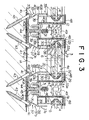
- Fig. 3 is a sectional view taken along arrow line F-F in Fig. 2;
- Fig. 4 is a perspective view showing a solar battery panel, in an assembled state, of the embodiment;
- Fig. 5 is a disassembled perspective view showing the solar battery panel of the embodiment;
- Fig. 6 is a sectional view showing a portion of the embodiment adjacent the ridge; and
- Fig. 7 is a sectional view showing a portion of the embodiment adjacent the eaves.
- Now, an embodiment of the invention will be described.
- Fig. 1 is a sectional view showing an embodiment of the invention applied to the house roof structure extending from the ridge to the eaves. Referring to Fig. 1, reference numeral 1 designates a rectangular roof panel with solar batteries according to the invention. The roof panel 1 is disposed such that its longitudinal direction is from the ridge M to the eaves N, and it constitutes a roof Y.
- The roof panel 1 with solar batteries comprises a
rectangular base panel 2 with apanel sheet 2b thereof disposed on a plurality ofcore members 2b assembled in longitudinal and transversal directions and a plurality ofsolar battery panels 3 provided on thebase panel 2. - Each
solar battery panel 3, as shown in Figs. 2 to 5, comprises a rectangular panel-shapedsolar battery 4, which has a large number of solar battery cells provided in a transparent plate,grading channel members 5 detachably fitted on the four edges of thesolar battery 4, and a frame of thesolar battery panel 3, which is detachably mounted around thegrading channel members 5 and consists of four frame members, i.e., an upper andlower frame member vertical frame members 8. - Each
grading channel member 5 is a channel-shaped member, in which an edge of thesolar battery 4 is fitted. It is made of a material having a certain elasticity, and it integrally has a substantially flatinner wall portion 9,side wall portions 10 extending from the opposite width direction edges of theinner wall portion 10 substantially at right angles thereto, a head portion 11 having a frust-conical sectional profile and terminating in theside wall portions 10, and a pair of tongue portions integrally extending from the inner surfaces of theside wall portions 10 toward each other (i.e., in the width direction). - The
inner wall portion 9 of thegrading channel member 5 has acentral engagement notch 5a extending in the longitudinal direction. Theinner wall portion 9 hasribs 9a extending from its opposite width direction edges and extending slight outward with respect to theside wall portions 10. Also, the head portion 11 has ribs lla slightly extending outward from its opposite width direction edges. With these ribs,engagement grooves 5b are formed in the opposite sides (i.e., upper and lower sides in the Figure) of thegrading channel member 5 such that they extend in the longitudinal direction thereof. - The
grading channel member 5 is fitted on thesolar battery 4 by fitting its engagement notch on the corresponding edge of thesolar battery 4 until the edge thereof is in contact with the inner surface of the head portion 11. In this state, the surfaces of theinner wall portion 9 defining theengagement notch 5a is held pushed against and in close contact with the edge of thesolar battery 4. In addition, thetongues 12 are elastically deformed by the inserted edge of thesolar battery 4, and their edges are in close contact with the solar battery edge. - The
frame members 6 to 8, as noted above, are mounted on thegrading channel members 5 fitted on the edges of thesolar battery 4 and form a frame thereof. These frame members are of three different kinds, i.e., the upper andlower frame members solar battery 4 and thevertical frame members 8 mounted on the other opposite sides. - The
solar battery 3 is disposed such that theupper frame member 6 is directed toward the ridge M, thelower frame member 7 is directed toward the eaves N and thevertical frame members 8 extend in the direction of inclination of the roof Y. Theseframe members 6 to 8 my be fabricated by extrusion molding aluminum or the like. - The upper and
lower frame members - Specifically, they each integrally have an outer and an
inner wall lower wall partitioning wall 17, which is provided between the outer andinner walls lower walls inner wall 14 has anopening 18 which extends in the longitudinal direction. The frame member is cylindrical having a substantially rectangular sectional profile, with an outside cavity 19 defined by the outer, inner, upper andlower walls 13 to 16. - The
lower wall 16 has anintegral projection 20 extending perpendicularly from its edge toward theupper wall 15. The edge of theinner wall 14 adjacent theopening 18 has ashort engagement projection 21, which extends toward thepartitioning wall 17 and is tightly fitted in thecorresponding engagement groove 5b of thegrading channel member 5. Thepartitioning wall 17 is parallel to the outer andinner walls partitioning wall 17, i.e., the inner surface thereof facing theouter wall 13, has an integralbolt hole piece 22. At the opposite longitudinal direction ends of theinner wall 14, the edge thereof on the side of theopening 18 is formed with arectangular notch 23. - The upper and
lower frame members upper frame member 6 theouter wall 13 has anintegral contact portion 24 having an L-shaped sectional profile, whereas in thelower frame member 7 thelower wall 16 has anintegral extension 25 extending outward to a greater extent than that of theupper frame member 6. - The
contact portion 24 extends in the longitudinal direction from the end of theouter wall 13 nearer thelower wall 16. Its end portion is provided with aseal member 22 applied thereto. Theextension 25 has aninclined portion 25a extending from theupper wall 15 in a slightly upwardly inclined direction and a portion extending from theinclined portion 25a in a direction parallel to theupper wall 15. Its lower surface is set such as to be slightly above the upper surface of thelower wall 16. - Adjacent
solar battery panels 3 are arranged with theirupper walls 15 set upward such that theouter wall 13 of the lower one of them abuts theinner wall 14 of the upper one of them via the interveningseal member 26. In this state, theextension 25 of thelower frame member 7 of the upper one of them covers theupper wall 15 of theupper frame member 6 of the lower one of them. - The
extension 25 has a length such that its end coincides with the end of theupper wall 15 of theupper frame member 6 in its state covering theupper wall 15 of theupper frame 6 of the lowersolar battery panel 3 as noted above. In the overlap zone of theextension 25 of thelower frame member 7 of the uppersolar battery panel 3 and theupper wall 15 of theupper frame member 6 of the lowersolar battery panel 3, if the roof 1 has an inclination, the gap between the two is set such that no rainwater will rise by the capillary phenomenon and enter between the adjacentsolar battery panels 3. - The upper and
lower frame members solar battery 4 via the respectivegrading channel members 5 by disposing theupper wall 15 on the surface side of thesolar battery 4, inserting the head portion 11 of each gradingchannel member 5 in eachopening 18 and engaging the upper andlower engagement projections 21 in the respective upper andlower engagement grooves 5b. - In this state, the
opening 18 in each of the upper andlower frame members channel member 5, and an inner cavity 19b is formed on the inner side of theinner wall 14. - The
vertical frame member 8, as shown in Fig. 3, integrally has an outer and aninner wall lower wall securement portion 31 extending outward from the lower edge of theouter wall 27. Theinner wall 28 has anopening 32 extending in the longitudinal direction. The frame member thus is cylindrical in shape having a rectangular sectional profile. - The
lower wall 30 is located on the inner side of the lower edge of the outer andinner walls opening 32 noted above is formed in theinner wall 28 between the lower andupper walls inner wall 28 adjacent theopening 32 has ashort engagement projection 34, which extends toward theouter wall 27 and is tightly engaged in thecorresponding engagement groove 5b of thegrading channel member 5. Each edge of theinner wall 28 has arectangular notch 35. - The
vertical frame member 8 as described above, is mounted on thesolar battery 4 via thegrading channel member 5 by disposing theupper wall 29 on the surface side of thesolar battery 4, inserting the head portion 11 of thegrading channel 5 in theopening 32 and engaging the upper andlower engagement projections 34 in the upper andlower engagement grooves 5b. In this state, theopening 32 of thevertical frame member 8 is closed by the head portion 11 of thegrading channel member 5, and anupper cavity 33a is formed inside theinner wall 28. - By mounting the upper, lower and
vertical frame members 6 to 8 via the respectivegrading channel members 5 as noted above, the opposite ends of the upper andlower frame members vertical frame members 8 with the engagement of thenotches outer walls 29 of thevertical frame members 8 cover theouter walls 29 of the upper andlower frame members frame members 6 to 8 are finally mounted on the four edges of thesolar battery 4 via thegrading channel members 5 by screwingbolts 36, which penetrate theouter walls 27 of thevertical frame members 8, through thebolt hole pieces 22 of the upper andlower frame members solar battery panel 3 is assembled. - Fig. 4 shows the
solar battery panel 3 in its assembled state. Fig. 5 shows it in a disassembled state. - In its assembled state, the opposite ends of the upper and
lower frame members vertical frame members 8 with the engagement of thenotches lower frame members upper cavities 33a of thevertical frame members 8 are communicated with one another. Further, the surfaces of theupper walls frame members 6 to 8 are at a somewhat higher level than the surface of thesolar battery 4. Thus, the surface of the entirety of thesolar battery panel 3 has a rectangular recess 4a corresponding to thesolar battery 4. - A plurality of
solar battery panels 3, having the construction as described above, are arranged (for instance two panels transversally and five panels longitudinally) over and secured to the upper surface of aface plate 2b of thebase panel 2. However, they are not directly secured to theface plate 2b, but are secured to gutter-like support rails 37 which are secured to theface plate 2b. - The
support rail 37, as shown in Fig. 3, has a vertically two-stage structure, comprising a gutter-like frame 38 having a substantially U-shaped sectional profile and open at the top and a plate-like support 39 formed within theframe 38, thesupport 30 being common to anupper gutter section 37a and a lowercylindrical section 37b. - The gutter-
like frame 38 has a pair of, i.e., left and right,vertical walls 40. In thecylindrical section 37b, one of thevertical walls 40 extends basically substantially upright although it has a slight bent profile 40a formed on the inner side in the width direction and bent in a fashion like a crankshaft profile. The othervertical wall 40 is aninclined wall 40b inclined toward the inner side. Thevertical wall 40 with the bent profile 40a is referred to as outervertical wall 40A, and that with theinclined portion 40b as inner vertical wall 40B. Theinclined portion 40b of the inner vertical wall 40B has a longitudinally extendingintegral securement piece 41 at right angles to theinclined portion 40b. The end of thesecurement piece 41 is located on the extension of the innervertical wall 40 in thegutter section 37a. - These support rails 37 are arranged in pairs of them at a predetermined interval on and secured to the
face plate 2b of thebase panel 2 withasphalt roofing 42 applied thereto such that their longitudinal direction is in the longitudinal direction of thebase panel 2 and that the pairedvertical frame members 8 of eachsolar battery panel 3 are accommodated in theircorresponding gutter sections 37a. - More specifically, the pair of support rails 37 are parallel such that their inner vertical walls 40B face each other.
Core members 2a extending in the longitudinal direction of thebase panel 2, are secured to the underside of theface plate 2b, on which the support rails 37 are supported. The support rails 37 are secured to thebase panel 2 by drivingwooden bolts 43 passed through thesecurement pieces 41. - The
asphalt roofing 42 is secured to theface plate 2b by double sideadhesive tapes 44, which are applied to portions of theface plate 2b that support the support rails 37. All thesolar battery panels 3 which are arranged in the longitudinal direction of thebase panel 2, are collectively secured to the base panel by the pairs of support rails 37. In each zone where adjacentsolar battery panels 3 face each other in the width direction (other than the direction of roof inclination), twosupport rails 37 are secured in close proximity of each other. - With these close proximity support rails 37, the outer
vertical walls 40A thereof face each other with a slight play defined between them. An upper and alower seal member vertical walls 40A, and a further seal member 47 is mounted such that it strides the two outer vertical walls. These seal members extend over the entire length of the outer vertical walls. The space between the adjacentsolar battery panels 3 is closed by agasket 49. - A plurality of
solar battery panels 3 are secured to the paired support rails 37 with theirupper frame member 6 on the side of the ridge M, with theirlower frame member 7 on the side of the eaves N and with theirvertical frame members 8 supported on thesupports 39 of thegutter sections 37a. - In this state, under
upper cavity 33a of eachvertical frame member 8 is formed lower cavity 33b, which is defined by the outer andinner walls lower wall 30 andsupport 38. The upper andlower cavities 33a and 33b of thevertical frame member 8 are communicated with the inside of thegutter section 37a of thesupport rail 37, that is, the inner cavities 10b of the upper andlower frame members gutter sections 37a of the paired support rails 37 via theupper cavities 33a of thevertical frame members 8. - Adjacent ones of the
solar battery panels 3, which are secured to the pair support rails 37 (i.e., arranged in the longitudinal direction of the base panel 2) are abutted against each other via the interveningseal member 26 noted above. In this state, theextension 25 of thelower frame member 7 of thesolar battery panel 3, which is disposed as roof Y on the side of the ridge M, covers theupper wall 15 of theupper frame member 6 of thesolar battery panel 3 on the side of the eaves N. The end of theextension 25 coincides with the end of theupper wall 15. - In each zone of connection of adjacent
solar battery panels 3, areinforcement member 48 is secured thereto. In this embodiment of the roof panel 1 with solar batteries, in which a plurality ofsolar battery panels 3 are disposed over thebase panel 2 via the support rails 37, ventilating layers 1A are formed between thesolar battery panels 3 and thebase panel 2. These ventilating layers 1A are defined by theframe members 6 to 8 and support rails 37. - The roof panel 1 with solar batteries as above, is secured as house roof Y to beams (not shown) such that it extends from the ridge M of the eaves M with the
upper frame member 6 of each securedsolar battery panel 3 directed toward the ridge M. - The ridge M, as shown in Fig. 6, comprises a
ridge beam 50, eachcoupling beam 51, each upper beam 52, each ventilatingstructure support 53, each ventilatingstructure 54, etc. A ridgewater blocking member 55 is disposed between theupper frame member 6 of thesolar battery panel 3 closest to the ridge M and the ventilatingstructure support 53. The gap between the lower edge of the ridgewater blocking member 55 and theupper frame member 6 is closed by aseal member 56 of urethane or like material. - The ventilating layers 1A of the roof panel 1 have their end on the side of the ridge M communicated with the inside of the ventilating
structure 54 and thence to the outside of the house. - The eaves N, as shown in Fig. 7, has a
coupling beam 60 and agutter 61. A predetermined space is provided between thesolar battery panel 3 closest to the eaves N and the inner or outer end thereof. An eaves panel 62 is disposed to entirely cover this space. An eaveswater blocking plate 63 is provided on the eaves panel 62. In the eaves N, the eaves panel 62 is secured to the parallel support rails 37 extending in the longitudinal direction. A lower eaveswater blocking plate 65 is on a portion of the top surface of thebase panel 2 corresponding to the lower end of the eaves N. Thewater blocking plates opening 65 defined by them extends in thegutter 61. Theopening 65 is closed by a perforated ventilatingmember 66. - The ventilating layers 1A of the roof panel 1 face the ventilating
member 66 at their end on the side of the eaves N and are communicated with the outside of the house through numerous pores of the perforated ventilatingmember 66. - The
gutter 61 is provided on the eaves N viabrackets coupling beam 60 and a hangingmember 69. - While the above roof structure is an embodiment of the invention, in this roof structure, a plurality of
solar battery panels 3 are supported on the gutter-like support rails 7, and seam zones of adjacentsolar battery panels 3 arranged side by side in the horizontal direction are supported by the support rails 37. The seam zones thus can provide water blocking without need of any special water blocking structure. - More specifically, rainwater falling on the roof flows along the
solar battery panels 3 or support rails 37 to thegutter 61. - First, rainwater flowing along the
solar battery panels 3 flows along the surface of each solar battery panel in the order ofupper frame member 6,solar battery 4 andlower frame member 7. Since theextension 25 of thelower frame member 7 covers theupper wall 15 of the upper frame member of the adjacent lowersolar battery panel 3, rainwater will not enter the solar battery panels through the gap between these upper and lower frame members. - In addition, since a certain length is ensured for the overlap zone between the two frame members, even in the presence of a strong wind no rainwater will enter the
solar battery panels 3. - Further, since the end of the
extension 25 of thelower frame member 7 coincides with the end (i.e., inner end) of theupper frame member 6 of the adjacent lowersolar battery panel 3, thelower frame member 7 is not exposed on the surface. It is thus possible to obtain improvement of the appearance. - Further, if rainwater flowing over the
solar battery panels 3 enters the gap betweensolar battery 4 andgrading channel members 5, it is reliably drained through the inside of the upper, lower andvertical frame members 6 to 8. - More specifically, rainwater intruding through the gaps between
solar battery 4 andgrading channel members 5, is led by theengagement projections frame members 6 to 8 to enter the inner andouter cavities 19b and 33a. Since the inner cavities 19b of the upper and lower frame members and theupper cavities 33a of thevertical frame members 8 are communicated with one another, the rainwater that enters the inner cavity of the upper orlower fame member upper cavities 33a of thevertical frame members 8. The rainwater entering theupper cavities 33a of thevertical frame members 8, is led in the downward inclined direction and through the continuousupper cavities 33a in the adjacentsolar battery panel 3 on the side of the eaves N to eventually reach the top surface of the eaveswater blocking plate 63 and thence flow down into thegutter 61, or it falls at intermediate positions into the inside ofgutter sections 37a of support rails 37 to flow down to the eaves N and enter thegutter 61 through the pores of the ventilatingmember 66. - Rainwater flowing along the
support rail 37 flows over thegasket 49. If rainwater entersgutter section 37 of thesupport rail 37 through betweengasket 49 andvertical frame member 8, it flows along thegutter section 37a down to the eaves N and falls into thegutter 61 through the ventilating pores of the ventilatingmember 66. - Rainwater flowing along the
gutter section 37a may leak down through the portions of thesupport 39 that are penetrated by self-tapping bolts 70. However, since thesupport rail 37 has the two-stage structure comprising thegutter section 37b and the lowercylindrical section 37b, the leaking rainwater is received in the lowercylindrical section 37b and does not further leak down but completely flows down along thecylindrical section 37b into thegutter 61. It is thus possible to completely prevent leakage of rainwater. - Further, since the support rails 37 are arranged parallel such that every two of them are disposed in back-to-back arrangement in each zone, in which adjacent
solar battery panels 3 face each other in the direction perpendicular to the direction of roof inclination, only one of these back-to-back arrangement support rails (on the side of the inner vertical wall 40B) may be used for the support, that is, it is possible to use the same kind of support frames at the end of the horizontal solar battery arrangement (without adjacent solar battery in the direction of roof inclination) and also at intermediate positions of the flow (with adjacent solar battery). - Further, since the two back-to-back arrangement support rails 37 are arranged such that the
seal members vertical walls 40A and that the seal member 47 is mounted such as to stride the upper ends of the two outervertical walls 40A, it is possible to ensure the water blocking between the two support rails 37. - Further, in the above roof structure, air of winds flowing outside is led through the ventilating pores of the ventilating
member 66 provided at the eaves N and through the ventilating layers 1A in the roof panel 1 into theridge ventilating structure 54 to be discharged thence to the outside of the house. - Such flow of winds (i.e., air) effects heat dissipation to suppress temperature rise of the
solar batteries 4. It is thus possible to maintain a high energy conversion efficiency of thesolar batteries 4 and permit stable power supply. - Further, the ventilating
member 66, which serves as an inlet of air to the ventilating layers 1A, can also serve the function of a spacer for maintaining a constant space between the upper and lower eaveswater blocking members - Further, rainwater which may rarely enter the
solar batteries 4 from the surroundings thereof, it is received by the surface of thebase panel 2 facing the ventilating layers 1A (which is provided with the water-proof asphalt roofing 42 applied to it), and thus can be drained toward the eaves N. - Further, since the
solar battery panel 3 in this embodiment has the recess 4a in its surface in correspondence to thesolar battery 4, at the time of the snowfall the recess 4a may serve to collect a certain amount of snow and provide a snow blocking effect.
Claims (20)
- A roof panel with solar batteries comprising:
a base panel disposed along the roof inclination from the ridge to the eaves and having a plurality of parallel gutter-like support rails secured at the top and extending in the direction of roof inclination; and
a plurality of solar battery panels disposed over said base panel and each including a solar battery in the form of a rectangular disk and a frame mounted around said solar battery, said frame being supported such that it is accommodated inside associated ones of said support rails. - The roof panel with solar batteries according to claim 1, wherein:
said support rails each have a two-stage structure including a gutter section capable of accommodating an associated portion of each said frame and a cylindrical section formed under and integral with said gutter section; and
each said frame is supported such that it is accommodated inside associated ones of said gutter sections. - The roof panel with solar batteries according to claim 1, wherein:
each said frame includes four cylindrical frame members, two of said frame members being an upper and a lower frame member mounted on parallel two of the four edges of each said solar battery, the other two of said frame members being a left and a right vertical frame member mounted on the other two of said four edges; and
said left and right vertical frame members are supported such that they are accommodated inside associated ones of said gutter-like support rails, at least the inner space in said lower frame member being communicated with the inside of said associated gutter-like support rails. - The roof panel with solar batteries according to claim 2, wherein:
each said frame includes four cylindrical frame members, two of said frame members being an upper and a lower frame member mounted on parallel two of the four edges of each said solar battery, the other two of said frame members being a left and a right vertical frame member mounted on the other two of said four edges; and
said left and right vertical frame members are supported such that they are accommodated inside associated ones of said gutter-like support rails, at least the inner space in said lower frame member being communicated with the inside of said associated gutter-like support rails. - A roof panel with solar batteries comprising:
a base panel disposed along the roof inclination from the ridge to the eaves; and
a plurality of solar battery panels disposed over said base panel and each including a solar battery in the form of a rectangular disk and a frame mounted around said solar battery, said frame having an extension extending from its eaves side portion and covering the top of a ridge side portion of the frame of the eaves side adjacent solar battery panel, said extension having an end substantially aligned to the eaves side end of a ridge side portion of the frame of the eaves side adjacent solar battery panel. - The roof panel with solar batteries according to claim 5, which further comprises:
a plurality of parallel gutter-like support rails secured to the top of said base panel and extending in the direction of the roof inclination;
said support rails each having a gutter-like two-stage structure including a gutter section capable of accommodating an associated portion of each said frame and cylindrical section formed under and integral with said gutter section;
said frame being supported such that it is accommodated inside associated ones of said gutter sections. - The roof panel with solar batteries according to claim 5, wherein:
each said frame includes four cylindrical frame members, two of said frame members being an upper and a lower frame member mounted on parallel two of the four edges of each said solar battery, the other two of said frame members being a left and a right vertical frame member mounted on the other two of said four edges; and
said left and right vertical frame members are supported such that they are accommodated inside associated ones of said gutter-like support rails, at least the inner space in said lower frame member being communicated with the inside of said associated gutter-like support rails. - A roof panel with solar batteries comprising:
a base panel disposed along the roof inclination from the ridge to the eaves and having a plurality of parallel gutter-like support rails secured at the top and extending in the direction of the roof inclination, each said support rail having a two-stage structure including a gutter section capable of accommodating an associated portion of each said frame and a cylindrical section formed under and integral with said gutter section; and
a plurality of solar battery panels disposed over said base panel and each including a solar battery in the form of a rectangular disk and a frame mounted around said solar battery, said frame being supported such that it is accommodated inside associated ones of said support rails, said frame including four cylindrical members, two of said frame members being an upper and a lower frame member mounted on parallel two of the four edges of said solar battery, the other two of said frame members being a left and a right vertical frame member mounted on the other two of said four edges, said left and right vertical frame members being supported such that they are accommodated inside associated ones of said gutter-like support rails, at least the inner space in said lower frame member being communicated with the inside of said associated gutter-like support rails, said frame having an extension extending from its eaves side portion and covering the top of a ridge side portion of the frame of the eaves side adjacent solar battery panel, said extension having an end substantially aligned to the eaves side end of a ridge side portion of the frame of the eaves side adjacent solar battery panel. - The roof panel with solar batteries according to claim 8, wherein:
said support rails are provided in pairs each in correspondence to facing sides of adjacent ones of said solar battery panels in a direction perpendicular to the direction of roof inclination;
a seal member is provided between adjacent side vertical walls of said gutter sections of said paired adjacent support rails; and
another seal member is provided such that it strides the upper ends of said two adjacent side vertical walls. - The roof panel with solar batteries according to claim 8, wherein:
a predetermined space serving as a ventilating layer is formed between the back surface of each said solar battery panel and said base panel; and
said ventilating layer is open to the outside at its eaves and ridge side edges. - A roof structure with solar batteries comprising:
a roof having a base panel disposed along the roof inclination from the ridge side to the eaves side, with a plurality of parallel gutter-like support rails secured to the roof top such as to extend in the direction of the roof inclination; and
a plurality of solar battery panels disposed over said base panel and each including a solar battery in the form of a rectangular disk and a frame mounted around said solar battery, said frame being supported such that it is accommodated inside associated ones of said support rails. - The roof structure with solar batteries according to claim 11, wherein:
said support rails each have a two-stage structure including a gutter section capable of accommodating an associated portion of each said frame and a cylindrical section formed under and integral with said gutter section; and
each said frame is supported such that it is accommodated inside associated ones of said gutter sections. - The roof structure with solar batteries according to claim 11, wherein:
each said frame includes four cylindrical frame members, two of said frame members being an upper and a lower frame member mounted on parallel two of the four edges of each said solar battery, the other two of said frame members being a left and a right vertical frame member mounted on the other two of said four edges; and
said left and right vertical frame members are supported such that they are accommodated inside associated ones of said gutter-like support rails, at least the inner space in said lower frame member being communicated with the inside of said associated gutter-like support rails. - The roof structure with solar batteries according to claim 12, wherein:
each said frame includes four cylindrical frame members, two of said frame members being an upper and a lower frame member mounted on parallel two of the four edges of each said solar battery, the other two of said frame members being a left and a right vertical frame member mounted on the other two of said four edges; and
said left and right vertical frame members are supported such that they are accommodated inside associated ones of said gutter-like support rails, at least the inner space in said lower frame member being communicated with the inside of said associated gutter-like support rails. - A roof structure with solar batteries comprising:
a roof including a base panel disposed along the roof inclination from the ridge to the eves; and
a plurality of solar battery panels disposed over said base panel and each including a solar battery in the form of a rectangular disk and a frame mounted around said solar battery, said frame having an extension extending from its eves side portion and covering the top of a ridge side portion of the frame of the eves side adjacent solar battery, said extension having an end substantially aligned to the eves side end of a ridge side portion of the frame of the eves side adjacent solar battery panel. - The roof structure with solar batteries according to claim 15, which further comprises:
a plurality of parallel gutter-like support rails secured to the top of said base panel and extending in the direction of the roof inclination;
said support rails each having a gutter-like two-stage structure including a gutter section capable of accommodating an associated portion of each said frame and cylindrical section formed under and integral with said gutter section;
said frame being supported such that it is accommodated inside associated ones of said gutter sections. - The roof structure with solar batteries according to claim 15, wherein:
each said frame includes four cylindrical frame members, two of said frame members being an upper and a lower frame member mounted on parallel two of the four edges o each said solar battery, the other two of said frame members being a left and a right vertical frame member mounted on the other two of said four edges; and
said left and right vertical frame members are supported such that they are accommodated inside associated ones of said gutter-like support rails, at least the inner space in said lower frame member being communicated with the inside of said associated gutter-like support rails. - A roof structure with solar batteries comprising:
a roof including a base panel disposed along the roof inclination from the ridge to the eaves and having a plurality of parallel gutter-like support rails secured at the top and extending in the direction of the roof inclination, each said support rail having a two-stage structure including a gutter section capable of accommodating an associated portion of each said frame and a cylindrical section formed under and integral with said gutter section; and
a plurality of solar battery panels disposed over said base panel and each including a solar battery in the form of a rectangular disk and a frame mounted around said solar battery, said frame being supported such that it is accommodated inside associated ones of said support rails, said frame including four cylindrical members, two of said frame members being an upper and a lower frame member mounted on parallel two of the four edges of said solar battery, the other two of said frame members being a left and a right vertical frame member mounted on the other two of said four edges, said left and right vertical frame members being supported such that they are accommodated inside associated ones of said gutter-like support rails, at least the inner space in said lower frame member being communicated with the inside of said associated gutter-like support rails, said frame having an extension extending from its eaves side portion and covering the top of a ridge side portion of the frame of the eaves side adjacent solar battery panel, said extension having an end substantially aligned to the eaves side end of a ridge side portion of the frame of the eaves side adjacent solar battery panel. - The roof structure with solar batteries according to claim 18, wherein:
said support rails are provided in pairs each in correspondence to facing sides of adjacent ones of said solar battery panels in a direction perpendicular to the direction of roof inclination;
a seal member is provided between adjacent side vertical walls of said gutter section of said paired adjacent support rails; and
another seal member is provided such that it strides the upper ends of said two adjacent side vertical walls. - The roof structure with solar batteries according to claim 18, wherein:
a predetermined space serving as a ventilating layer is formed between the back surface of each said solar battery panel and said base panel; and
said ventilating layer is open to the outside at its eaves and ridge side edges.
Applications Claiming Priority (9)
| Application Number | Priority Date | Filing Date | Title |
|---|---|---|---|
| JP8225093 | 1993-04-08 | ||
| JP08224993A JP3298695B2 (en) | 1993-04-08 | 1993-04-08 | Roof structure with solar cells |
| JP08225193A JP3352752B2 (en) | 1993-04-08 | 1993-04-08 | Roof panel with solar cells |
| JP82251/93 | 1993-04-08 | ||
| JP82250/93 | 1993-04-08 | ||
| JP8225193 | 1993-04-08 | ||
| JP5082250A JPH06294184A (en) | 1993-04-08 | 1993-04-08 | Roof panel with solar cell |
| JP82249/93 | 1993-04-08 | ||
| JP8224993 | 1993-04-08 |
Publications (3)
| Publication Number | Publication Date |
|---|---|
| EP0619404A2 true EP0619404A2 (en) | 1994-10-12 |
| EP0619404A3 EP0619404A3 (en) | 1995-06-07 |
| EP0619404B1 EP0619404B1 (en) | 2000-08-02 |
Family
ID=27303858
Family Applications (1)
| Application Number | Title | Priority Date | Filing Date |
|---|---|---|---|
| EP94302272A Expired - Lifetime EP0619404B1 (en) | 1993-04-08 | 1994-03-29 | Roof panel with solar batteries and roof structure with solar batteries |
Country Status (7)
| Country | Link |
|---|---|
| US (1) | US5509973A (en) |
| EP (1) | EP0619404B1 (en) |
| AU (1) | AU684742B2 (en) |
| CA (1) | CA2120650C (en) |
| DE (1) | DE69425393T2 (en) |
| FI (1) | FI941639A7 (en) |
| NO (1) | NO305613B1 (en) |
Cited By (6)
| Publication number | Priority date | Publication date | Assignee | Title |
|---|---|---|---|---|
| EP0905795A3 (en) * | 1997-09-24 | 1999-09-22 | Matsushita Electric Works, Ltd. | Mounting system for installing an array of solar battery modules of a panel-like configuration on a roof |
| WO2000002256A1 (en) * | 1998-07-03 | 2000-01-13 | Enecolo Ag | Frame made of shaped sections and designed for plate-like elements, and array of several such frames |
| FR2915230A1 (en) * | 2007-04-20 | 2008-10-24 | Imphy Alloys Sa | BATI SUPPORT OF A PANEL SUCH AS A PHOTOELECTRIC PANEL AND EXTERIOR WALL OF A BUILDING COMPRISING SUCH WALLS |
| FR2949799A1 (en) * | 2009-09-04 | 2011-03-11 | Gauthier Solar Systeme | Device for integrating photovoltaic solar panels on roof to produce electricity, has two aluminum profiles arranging row of solar panels on roof, where row is defined by alternate placement of two types of photovoltaic solar panels |
| FR2976007A1 (en) * | 2011-05-31 | 2012-12-07 | All Star Corp Ltd | MODULAR COVER DEVICE |
| EP2530404A3 (en) * | 2011-05-31 | 2014-06-11 | All Star Corporation Limited | Modular cover |
Families Citing this family (24)
| Publication number | Priority date | Publication date | Assignee | Title |
|---|---|---|---|---|
| JP3396568B2 (en) * | 1995-11-14 | 2003-04-14 | ミサワホーム株式会社 | Mounting structure for sheet solar cells |
| US5647915A (en) * | 1996-06-13 | 1997-07-15 | Zukerman; Charles | Solar energy panel |
| NO20000899A (en) * | 2000-02-23 | 2001-04-09 | Soerveggen As | Building construction |
| US6799398B1 (en) * | 2002-06-18 | 2004-10-05 | Skytech Systems, Inc. | Modular system for securing flat panels to a curved support structure |
| JP4315665B2 (en) * | 2002-10-30 | 2009-08-19 | シャープ株式会社 | End face sealing member of solar cell module and solar cell module using the same |
| US8141306B2 (en) * | 2004-10-22 | 2012-03-27 | Kyocera Corporation | Solar battery module device and method of installing the same |
| US7956279B2 (en) * | 2005-03-18 | 2011-06-07 | Kyocera Corporation | Solar cell module and solar cell array |
| US8273980B2 (en) * | 2005-09-30 | 2012-09-25 | General Electric Company | Photovoltaic roof ridge cap and installation method |
| US20080035140A1 (en) * | 2006-05-26 | 2008-02-14 | Bp Corporation North America Inc. | Solar Roof Tile |
| DE102007020151A1 (en) * | 2007-04-26 | 2008-10-30 | C.M.S. Gmbh | Solar module for pitched roof |
| KR20100024989A (en) * | 2007-06-19 | 2010-03-08 | 비피 코포레이션 노쓰 아메리카 인코포레이티드 | Solar module with a frame for mounting a solar panel |
| FR2926098B1 (en) * | 2008-01-04 | 2010-02-19 | Photowatt Internat | MODULAR ELEMENT WITH PHOTOVOLTAIC MODULE. |
| US8748733B2 (en) * | 2008-03-27 | 2014-06-10 | Panelclaw, Inc. | Solar module integration system |
| US8832938B2 (en) * | 2008-03-27 | 2014-09-16 | Panelclaw, Inc. | Ground mounted solar module integration system |
| KR100921658B1 (en) * | 2008-10-06 | 2009-10-15 | 한국철강 주식회사 | Solar cell module |
| US20120060434A1 (en) * | 2010-09-13 | 2012-03-15 | Certain Teed Corporation | Photovoltaic modules |
| US20120073630A1 (en) * | 2010-09-28 | 2012-03-29 | Perfect Source Technology Corp. | Rectangular protective frame for solar cell module |
| CA2739766C (en) | 2011-05-10 | 2016-08-23 | Robert Richardson | Roof solar panel for conventional sloping roof and shingle integration |
| US9052123B2 (en) | 2011-07-11 | 2015-06-09 | Panelclaw Group, Inc. | Solar module integration system with thermal compensation |
| US20140299177A1 (en) * | 2013-04-08 | 2014-10-09 | Xiaolin Sha | Integrated roof solar power system |
| US9294032B2 (en) | 2013-11-08 | 2016-03-22 | Robert Richardson | Modular roof solar panel for conventional roof and roofing integration |
| US11575343B2 (en) * | 2013-12-13 | 2023-02-07 | Quick Mount PV | Waterproofing mounting system for attaching solar modules to a roof |
| CN208874502U (en) * | 2018-04-13 | 2019-05-17 | 广东汉能薄膜太阳能有限公司 | A solar power tile |
| AU2023336071A1 (en) * | 2023-02-15 | 2024-08-29 | Trina Solar Co., Ltd | Photovoltaic profile, photovoltaic roof tile module and photovoltaic roof installation system |
Family Cites Families (11)
| Publication number | Priority date | Publication date | Assignee | Title |
|---|---|---|---|---|
| DE2712532A1 (en) * | 1977-03-22 | 1978-09-28 | Pantherm Gmbh | Solar heating module - with carrier element for transparent panes and heat recovery panels enclosing tubes for heating medium |
| GB2000860B (en) * | 1977-07-06 | 1982-08-04 | Showa Aluminium Co Ltd | Solar collector |
| FR2465315A1 (en) * | 1979-09-10 | 1981-03-20 | Radiotechnique Compelec | PHOTOVOLTAIC GENERATING PANEL ASSURING THE SEALING IN THE INTEMPERIES OF A ROOF BY DIRECT INSTALLATION ON THE FRAMEWORK |
| JPS59175169A (en) * | 1983-03-24 | 1984-10-03 | Fuji Electric Co Ltd | Flashing structure of solar battery panel |
| US4636577A (en) * | 1983-08-29 | 1987-01-13 | Thomas & Betts Corporation | Solar panel module and support therefor |
| US4677248A (en) * | 1985-09-13 | 1987-06-30 | Lacey Thomas G | Apparatus for mounting solar cells |
| US4936063A (en) * | 1989-05-19 | 1990-06-26 | Humphrey John B | Frame flanges for mounting photovoltaic modules direct to roof structural framing |
| JPH0467349A (en) * | 1990-07-02 | 1992-03-03 | Tokin Corp | Suction pad for flexible magnetic disk and manufacture thereof |
| US5092939A (en) * | 1990-11-30 | 1992-03-03 | United Solar Systems Corporation | Photovoltaic roof and method of making same |
| US5164020A (en) * | 1991-05-24 | 1992-11-17 | Solarex Corporation | Solar panel |
| US5338369A (en) * | 1993-02-16 | 1994-08-16 | Rawlings Lyle K | Roof-integratable photovolatic modules |
-
1994
- 1994-03-29 EP EP94302272A patent/EP0619404B1/en not_active Expired - Lifetime
- 1994-03-29 DE DE69425393T patent/DE69425393T2/en not_active Expired - Fee Related
- 1994-03-31 AU AU59244/94A patent/AU684742B2/en not_active Ceased
- 1994-04-06 US US08/223,507 patent/US5509973A/en not_active Expired - Fee Related
- 1994-04-06 CA CA002120650A patent/CA2120650C/en not_active Expired - Fee Related
- 1994-04-07 NO NO941263A patent/NO305613B1/en not_active IP Right Cessation
- 1994-04-08 FI FI941639A patent/FI941639A7/en unknown
Cited By (12)
| Publication number | Priority date | Publication date | Assignee | Title |
|---|---|---|---|---|
| EP0905795A3 (en) * | 1997-09-24 | 1999-09-22 | Matsushita Electric Works, Ltd. | Mounting system for installing an array of solar battery modules of a panel-like configuration on a roof |
| US6105317A (en) * | 1997-09-24 | 2000-08-22 | Matsushita Electric Works, Ltd. | Mounting system for installing an array of solar battery modules of a panel-like configuration on a roof |
| WO2000002256A1 (en) * | 1998-07-03 | 2000-01-13 | Enecolo Ag | Frame made of shaped sections and designed for plate-like elements, and array of several such frames |
| FR2915230A1 (en) * | 2007-04-20 | 2008-10-24 | Imphy Alloys Sa | BATI SUPPORT OF A PANEL SUCH AS A PHOTOELECTRIC PANEL AND EXTERIOR WALL OF A BUILDING COMPRISING SUCH WALLS |
| WO2008145903A1 (en) | 2007-04-20 | 2008-12-04 | Arcelormittal - Stainless And Nickel Alloys | Bearing frame for a panel photoelectric such as a photoelectric panel and building external wall including such panel |
| EA016444B1 (en) * | 2007-04-20 | 2012-05-30 | Арселормитталь-Стейнлесс Энд Никель Эллойз | SUPPORTING FRAME OF A PHOTOELECTRIC PANEL AND EXTERNAL WALL OF BUILDING WITH SUCH FRAMES |
| EA016444B9 (en) * | 2007-04-20 | 2012-07-30 | Арселормитталь-Стейнлесс Энд Никель Эллойз | SUPPORTING FRAME OF A PHOTOELECTRIC PANEL AND EXTERNAL WALL OF BUILDING WITH SUCH FRAMES |
| AU2008257227B2 (en) * | 2007-04-20 | 2013-05-02 | Arcelormittal - Stainless And Nickel Alloys | Bearing frame for a panel photoelectric such as a photoelectric panel and building external wall including such panel |
| US8549800B2 (en) | 2007-04-20 | 2013-10-08 | Aperam Alloys Imphy | Bearing frame for a panel such as a photoelectric panel and building external wall including such frames |
| FR2949799A1 (en) * | 2009-09-04 | 2011-03-11 | Gauthier Solar Systeme | Device for integrating photovoltaic solar panels on roof to produce electricity, has two aluminum profiles arranging row of solar panels on roof, where row is defined by alternate placement of two types of photovoltaic solar panels |
| FR2976007A1 (en) * | 2011-05-31 | 2012-12-07 | All Star Corp Ltd | MODULAR COVER DEVICE |
| EP2530404A3 (en) * | 2011-05-31 | 2014-06-11 | All Star Corporation Limited | Modular cover |
Also Published As
| Publication number | Publication date |
|---|---|
| AU5924494A (en) | 1994-10-13 |
| EP0619404A3 (en) | 1995-06-07 |
| DE69425393D1 (en) | 2000-09-07 |
| AU684742B2 (en) | 1998-01-08 |
| CA2120650C (en) | 2003-11-25 |
| NO305613B1 (en) | 1999-06-28 |
| FI941639A0 (en) | 1994-04-08 |
| US5509973A (en) | 1996-04-23 |
| CA2120650A1 (en) | 1994-10-09 |
| EP0619404B1 (en) | 2000-08-02 |
| NO941263L (en) | 1994-10-10 |
| DE69425393T2 (en) | 2000-12-28 |
| FI941639A7 (en) | 1994-10-09 |
| NO941263D0 (en) | 1994-04-07 |
Similar Documents
| Publication | Publication Date | Title |
|---|---|---|
| EP0619404B1 (en) | Roof panel with solar batteries and roof structure with solar batteries | |
| KR100697499B1 (en) | Panel Frame System | |
| US5524401A (en) | Roof with solar battery | |
| US4936063A (en) | Frame flanges for mounting photovoltaic modules direct to roof structural framing | |
| KR102260055B1 (en) | Ceiling Integrated Photovoltaic Roof Structure with Drainway | |
| US8341900B2 (en) | Structure for mounting on a building wall frames for holding panels such as photovoltaic panels | |
| US8181402B2 (en) | Building-integrated photovoltaic power unit | |
| US4506484A (en) | Panel wall system | |
| US20100287852A1 (en) | Modular elements for building roofs | |
| US4212291A (en) | Batten for mounting a unitary solar collector panel | |
| GB2476342A (en) | Method for securing a solar panel supporting rail to a roof using a clip | |
| US4463534A (en) | Greenhouse structures and methods for their construction | |
| EP2072708B1 (en) | Panel structure for roofs and the like | |
| GB2236792A (en) | Extruded glazing bar system on wooden support structure | |
| US11047133B1 (en) | Modular rooftop with variable slope panels | |
| JPH06294184A (en) | Roof panel with solar cell | |
| JP3352752B2 (en) | Roof panel with solar cells | |
| JPH09252657A (en) | Transmissive plate attaching structure for green house or the like | |
| JP2587133Y2 (en) | Roof panel with solar cells | |
| JP3308890B2 (en) | Vertical roofing exterior structure and heat collecting method using vertical roofing exterior structure | |
| JP3298695B2 (en) | Roof structure with solar cells | |
| JP3108289B2 (en) | Solar cell roof | |
| JP2001279821A (en) | Prefabricated building with arch-shaped roof | |
| JPH05239896A (en) | Roof with solar battery | |
| EP4136962B1 (en) | A greenhouse |
Legal Events
| Date | Code | Title | Description |
|---|---|---|---|
| PUAI | Public reference made under article 153(3) epc to a published international application that has entered the european phase |
Free format text: ORIGINAL CODE: 0009012 |
|
| AK | Designated contracting states |
Kind code of ref document: A2 Designated state(s): CH DE FR GB LI SE |
|
| PUAL | Search report despatched |
Free format text: ORIGINAL CODE: 0009013 |
|
| AK | Designated contracting states |
Kind code of ref document: A3 Designated state(s): CH DE FR GB LI SE |
|
| 17P | Request for examination filed |
Effective date: 19951124 |
|
| 17Q | First examination report despatched |
Effective date: 19980318 |
|
| GRAG | Despatch of communication of intention to grant |
Free format text: ORIGINAL CODE: EPIDOS AGRA |
|
| GRAG | Despatch of communication of intention to grant |
Free format text: ORIGINAL CODE: EPIDOS AGRA |
|
| GRAH | Despatch of communication of intention to grant a patent |
Free format text: ORIGINAL CODE: EPIDOS IGRA |
|
| GRAH | Despatch of communication of intention to grant a patent |
Free format text: ORIGINAL CODE: EPIDOS IGRA |
|
| GRAA | (expected) grant |
Free format text: ORIGINAL CODE: 0009210 |
|
| AK | Designated contracting states |
Kind code of ref document: B1 Designated state(s): CH DE FR GB LI SE |
|
| REG | Reference to a national code |
Ref country code: CH Ref legal event code: EP |
|
| ET | Fr: translation filed | ||
| REF | Corresponds to: |
Ref document number: 69425393 Country of ref document: DE Date of ref document: 20000907 |
|
| REG | Reference to a national code |
Ref country code: CH Ref legal event code: NV Representative=s name: R. A. EGLI & CO. PATENTANWAELTE |
|
| PGFP | Annual fee paid to national office [announced via postgrant information from national office to epo] |
Ref country code: SE Payment date: 20010327 Year of fee payment: 8 Ref country code: CH Payment date: 20010327 Year of fee payment: 8 |
|
| PLBE | No opposition filed within time limit |
Free format text: ORIGINAL CODE: 0009261 |
|
| STAA | Information on the status of an ep patent application or granted ep patent |
Free format text: STATUS: NO OPPOSITION FILED WITHIN TIME LIMIT |
|
| 26N | No opposition filed | ||
| REG | Reference to a national code |
Ref country code: GB Ref legal event code: IF02 |
|
| PG25 | Lapsed in a contracting state [announced via postgrant information from national office to epo] |
Ref country code: SE Free format text: LAPSE BECAUSE OF NON-PAYMENT OF DUE FEES Effective date: 20020330 |
|
| PG25 | Lapsed in a contracting state [announced via postgrant information from national office to epo] |
Ref country code: LI Free format text: LAPSE BECAUSE OF NON-PAYMENT OF DUE FEES Effective date: 20020331 Ref country code: CH Free format text: LAPSE BECAUSE OF NON-PAYMENT OF DUE FEES Effective date: 20020331 |
|
| EUG | Se: european patent has lapsed |
Ref document number: 94302272.3 |
|
| REG | Reference to a national code |
Ref country code: CH Ref legal event code: PL |
|
| PGFP | Annual fee paid to national office [announced via postgrant information from national office to epo] |
Ref country code: FR Payment date: 20030310 Year of fee payment: 10 |
|
| PGFP | Annual fee paid to national office [announced via postgrant information from national office to epo] |
Ref country code: GB Payment date: 20030326 Year of fee payment: 10 |
|
| PGFP | Annual fee paid to national office [announced via postgrant information from national office to epo] |
Ref country code: DE Payment date: 20030409 Year of fee payment: 10 |
|
| PG25 | Lapsed in a contracting state [announced via postgrant information from national office to epo] |
Ref country code: GB Free format text: LAPSE BECAUSE OF NON-PAYMENT OF DUE FEES Effective date: 20040329 |
|
| PG25 | Lapsed in a contracting state [announced via postgrant information from national office to epo] |
Ref country code: DE Free format text: LAPSE BECAUSE OF NON-PAYMENT OF DUE FEES Effective date: 20041001 |
|
| GBPC | Gb: european patent ceased through non-payment of renewal fee |
Effective date: 20040329 |
|
| PG25 | Lapsed in a contracting state [announced via postgrant information from national office to epo] |
Ref country code: FR Free format text: LAPSE BECAUSE OF NON-PAYMENT OF DUE FEES Effective date: 20041130 |
|
| REG | Reference to a national code |
Ref country code: FR Ref legal event code: ST |