EP0619199B1 - Sealing and wiping arrangement - Google Patents
Sealing and wiping arrangement Download PDFInfo
- Publication number
- EP0619199B1 EP0619199B1 EP94302279A EP94302279A EP0619199B1 EP 0619199 B1 EP0619199 B1 EP 0619199B1 EP 94302279 A EP94302279 A EP 94302279A EP 94302279 A EP94302279 A EP 94302279A EP 0619199 B1 EP0619199 B1 EP 0619199B1
- Authority
- EP
- European Patent Office
- Prior art keywords
- window pane
- cavity
- sealing
- wall portion
- strip
- Prior art date
- Legal status (The legal status is an assumption and is not a legal conclusion. Google has not performed a legal analysis and makes no representation as to the accuracy of the status listed.)
- Expired - Lifetime
Links
- 238000007789 sealing Methods 0.000 title claims description 44
- 239000000463 material Substances 0.000 claims description 10
- 239000002184 metal Substances 0.000 claims description 3
- 230000002787 reinforcement Effects 0.000 claims description 3
- 239000005357 flat glass Substances 0.000 description 13
- 238000010276 construction Methods 0.000 description 2
- 238000001125 extrusion Methods 0.000 description 2
- 229910000639 Spring steel Inorganic materials 0.000 description 1
- 239000000853 adhesive Substances 0.000 description 1
- 230000001070 adhesive effect Effects 0.000 description 1
- 238000004140 cleaning Methods 0.000 description 1
- 230000001419 dependent effect Effects 0.000 description 1
- 238000011161 development Methods 0.000 description 1
- 230000018109 developmental process Effects 0.000 description 1
- 229920001971 elastomer Polymers 0.000 description 1
- 239000013536 elastomeric material Substances 0.000 description 1
- 244000144992 flock Species 0.000 description 1
- 239000011521 glass Substances 0.000 description 1
- 238000000034 method Methods 0.000 description 1
- 230000004048 modification Effects 0.000 description 1
- 238000012986 modification Methods 0.000 description 1
- 229920000728 polyester Polymers 0.000 description 1
- 229920002635 polyurethane Polymers 0.000 description 1
- 239000004814 polyurethane Substances 0.000 description 1
- 239000012815 thermoplastic material Substances 0.000 description 1
- XLYOFNOQVPJJNP-UHFFFAOYSA-N water Substances O XLYOFNOQVPJJNP-UHFFFAOYSA-N 0.000 description 1
Images


Classifications
-
- B—PERFORMING OPERATIONS; TRANSPORTING
- B60—VEHICLES IN GENERAL
- B60J—WINDOWS, WINDSCREENS, NON-FIXED ROOFS, DOORS, OR SIMILAR DEVICES FOR VEHICLES; REMOVABLE EXTERNAL PROTECTIVE COVERINGS SPECIALLY ADAPTED FOR VEHICLES
- B60J10/00—Sealing arrangements
- B60J10/70—Sealing arrangements specially adapted for windows or windscreens
- B60J10/74—Sealing arrangements specially adapted for windows or windscreens for sliding window panes, e.g. sash guides
- B60J10/75—Sealing arrangements specially adapted for windows or windscreens for sliding window panes, e.g. sash guides for sealing the lower part of the panes
-
- B—PERFORMING OPERATIONS; TRANSPORTING
- B60—VEHICLES IN GENERAL
- B60J—WINDOWS, WINDSCREENS, NON-FIXED ROOFS, DOORS, OR SIMILAR DEVICES FOR VEHICLES; REMOVABLE EXTERNAL PROTECTIVE COVERINGS SPECIALLY ADAPTED FOR VEHICLES
- B60J10/00—Sealing arrangements
- B60J10/20—Sealing arrangements characterised by the shape
-
- B—PERFORMING OPERATIONS; TRANSPORTING
- B60—VEHICLES IN GENERAL
- B60J—WINDOWS, WINDSCREENS, NON-FIXED ROOFS, DOORS, OR SIMILAR DEVICES FOR VEHICLES; REMOVABLE EXTERNAL PROTECTIVE COVERINGS SPECIALLY ADAPTED FOR VEHICLES
- B60J10/00—Sealing arrangements
- B60J10/30—Sealing arrangements characterised by the fastening means
Definitions
- the invention relates to a sealing and wiping arrangement made of flexible material for sealing and wiping against a slidably movable window pane in a window opening of a motor vehicle, comprising a longitudinally extending strip arranged for mounting alongside an edge of the window opening adjacent the path of sliding movement of the window pane, the material of the strip defining a surface having a sealing zone for making area sealing contact with the sliding window pane, a cavity in the material of the strip and having a resilient outer wall portion extending longitudinally of the strip and defining at least part of the said surface, a protrusion on the outer wall portion of the cavity and extending both longitudinally along the strip and towards the path of sliding movement of the window pane so as to wipe the window pane as the latter slidably moves, the protrusion being resiliently movable with the resilient outer wall portion of the cavity in directions substantially perpendicular to the sliding movement of the window pane.
- the strip comprises a longitudinally extending cavity whose outer wall portion carries the surface with the sealing zone thereon as well as the protrusion. Movement of the protrusion in the direction substantially perpendicular to the sliding movement of the window glass depresses the outer wall portion into the cavity and thus moves the sealing zone away from the window glass.
- the invention aims to overcome this problem.
- the invention aims to overcome this problem.
- the known arrangement as first set forth above (GB-A-2 221 238) is characterised, in accordance with the invention, in that the protrusion is in the form of a wiper blade which is also resiliently movable relative to the said surface in the directions of sliding movement of the window pane, and in that the cavity and the outer wall portion thereof are local to the wiper blade so that the position of the strip relative to the path of sliding movement of the window pane, and the area contact of the sealing zone with the window pane are substantially unaffected by any said movement of the wiper blade, and the surface of the sealing zone acts as a continuous seal against the window pane.
- a rigid carrier member forming part of the door of a motor vehicle , carries a flexible sealing lip 2.
- the sealing lip 2 is directed angularly across the adjacent window opening 3 in the vehicle door through which the window pane 5 is slidably movable in an upward and downward direction.
- a panel edge 4 forming part of the vehicle door, engages the outer surface of the sealing lip 2.
- the sealing lip 2 has a sealing area having an upper portion 7 and a lower and substantially deeper portion 8.
- the sealing lip extends across the full width of the window, as do the sealing portions 7 and 8.
- the sealing portions 7 and 8 may be advantageously covered with flock secured to the sealing lip 2 such as by a modified polyurethane adhesive. Polyester 3.3d tex may be used, for example. As the window glass slides up and down, the sealing portions 7 and 8 maintain sealing contact with the glass and help to prevent ingress of drafts and water into the interior of the door and into the interior of the vehicle.
- the sealing and wiping arrangement includes a wiper lip 6. This is integrally carried by the sealing lip 2 and, as shown in Figure 1 is positioned within the sealing area and, in particular, between the portions 7 and 8 of the sealing area.
- the wiper lip 6 extends across the width of the window glass 5.
- the wiper lip 6 wipes, and cleans, the surface of the window glass.
- the wiper lip 6 is mounted on the outer flexible wall of a cavity 9 which is incorporated into the sealing lip 2 and is located immediately behind the wiper lip 6.
- the lip 6 flexes slightly in an upward and downward direction, corresponding with the movement of the window glass 5, and this improves its wiping action.
- the provision of the cavity 9 enables the wiper lip 6 to move in a direction substantially perpendicular to the plane of the window glass 5.
- This ability of the wiper lip 6, to flex in a direction perpendicular to the surface of the window glass 5, because of the provision of the cavity 9, is advantageous in that it enables the arrangement to accommodate quite large tolerances which may in practice exist in the distance between the surface of the window glass on the one hand and the mounting of the sealing lip 2 on the other. In practice, it is found that this distance can vary by as much as ⁇ 2.5 millimeters, giving a total possible range of 5 millimeters. Such large tolerances can be accommodated by the wiper blade 6, and its cleaning function is substantially improved.
- the sealing lip 2 is reinforced by a metal reinforcement strip 15.
- a metal reinforcement strip 15 This may be made of spring steel and may have any suitable construction, being, for example, about 0.1 millimeters thick. Its presence increases the efficiency of operation of the sealing lip 2 and ensures that it maintains proper sealing and wiping contact with the surface of the window glass over extended periods of time.
- the sealing lip 2 may be made of any suitable elastomer or thermoplastic material, a combination of such materials, or any other suitable material.
- the sealing lip is produced by extrusion and the metal reinforcement 15 may be incorporated into the extruded material by means of a cross-head extrusion process. Parts in Figures 2,3 and 4 corresponding to those in Figure 1 are similarly referenced.
- the arrangement shown in Figure 2 differs from that in Figure 1 in that the cavity 9 is not a closed cavity. Its front wall is constituted by a tongue 10 which is flexible and carries the wiper lip 6. The tongue 10 is extended so as to engage under a web 11. Such an arrangement also enables the wiper lip 6 to flex in an upward and downward direction corresponding to movement of the window pane 5 and also to move in a direction which is generally perpendicular to these directions.
- FIG. 3 The arrangement shown in Figure 3 is somewhat similar to that shown in Figure 1, except that the wiper lip is carried by a flexible connecting web 12 of reduced thickness, and the wiper lip 6 is itself of triangular cross-section.
- the wiper lip 6 is carried by a flexible connecting web 12 of reduced thickness, and the wiper lip 6 is itself of triangular cross-section.
- Such a construction increases the ability of the wiper lip 6 to flex in an upward and downward direction, corresponding to sliding movement of the window glass.
- the provision of the cavity 9 enables the wiper lip to move in the perpendicular direction.
- the wiper blade 6 is constrained to be movable between stop faces 14 defining free spaces 13. The operation is otherwise as already described.
Landscapes
- Engineering & Computer Science (AREA)
- Mechanical Engineering (AREA)
- Seal Device For Vehicle (AREA)
Description
- The invention relates to a sealing and wiping arrangement made of flexible material for sealing and wiping against a slidably movable window pane in a window opening of a motor vehicle, comprising a longitudinally extending strip arranged for mounting alongside an edge of the window opening adjacent the path of sliding movement of the window pane, the material of the strip defining a surface having a sealing zone for making area sealing contact with the sliding window pane, a cavity in the material of the strip and having a resilient outer wall portion extending longitudinally of the strip and defining at least part of the said surface, a protrusion on the outer wall portion of the cavity and extending both longitudinally along the strip and towards the path of sliding movement of the window pane so as to wipe the window pane as the latter slidably moves, the protrusion being resiliently movable with the resilient outer wall portion of the cavity in directions substantially perpendicular to the sliding movement of the window pane.
- Such an arrangement is shown in GB-A-2 221 238. In this arrangement, the strip comprises a longitudinally extending cavity whose outer wall portion carries the surface with the sealing zone thereon as well as the protrusion. Movement of the protrusion in the direction substantially perpendicular to the sliding movement of the window glass depresses the outer wall portion into the cavity and thus moves the sealing zone away from the window glass. Such an arrangement therefore reduces the sealing effectiveness of the sealing zone. The invention aims to overcome this problem.
- Such an arrangement is also shown in US-A-5 085 005. Again, however, the sealing zone extends over the outer wall portion of the cavity and may be lifted off the window pane by the movement of the protrusion. The zone cannot therefore provide continuous sealing contact against the window pane.
- The invention aims to overcome this problem.
- Therefore, the known arrangement as first set forth above (GB-A-2 221 238) is characterised, in accordance with the invention, in that the protrusion is in the form of a wiper blade which is also resiliently movable relative to the said surface in the directions of sliding movement of the window pane, and in that the cavity and the outer wall portion thereof are local to the wiper blade so that the position of the strip relative to the path of sliding movement of the window pane, and the area contact of the sealing zone with the window pane are substantially unaffected by any said movement of the wiper blade, and the surface of the sealing zone acts as a continuous seal against the window pane.
- Further developments in line with
claim 1 are referred to in thedependent claims 2 to 7. - Sealing and wiping arrangements will now be described, by way of example only, with reference to the accompanying diagrammatic drawings in which:
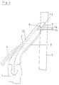
- Figure 1 is a side view of one of the arrangements, showing it in use;
- Figure 2 is a view corresponding to Figure 1 showing a modified form of the arrangement;
- Figure 3 corresponds to Figures 1 and 2 and shows a further modified arrangement; and
- Figure 4 corresponds to the preceding Figures and shows yet another modification of the arrangement.
- As shown in Figure 1, a rigid carrier member, forming part of the door of a motor vehicle, carries a
flexible sealing lip 2. Thesealing lip 2 is directed angularly across the adjacent window opening 3 in the vehicle door through which thewindow pane 5 is slidably movable in an upward and downward direction. - A
panel edge 4, forming part of the vehicle door, engages the outer surface of the sealinglip 2. - The
sealing lip 2 has a sealing area having anupper portion 7 and a lower and substantially deeper portion 8. The sealing lip extends across the full width of the window, as do thesealing portions 7 and 8. The sealingportions 7 and 8 may be advantageously covered with flock secured to the sealinglip 2 such as by a modified polyurethane adhesive. Polyester 3.3d tex may be used, for example. As the window glass slides up and down, thesealing portions 7 and 8 maintain sealing contact with the glass and help to prevent ingress of drafts and water into the interior of the door and into the interior of the vehicle. - In addition, however, the sealing and wiping arrangement includes a
wiper lip 6. This is integrally carried by thesealing lip 2 and, as shown in Figure 1 is positioned within the sealing area and, in particular, between theportions 7 and 8 of the sealing area. Thewiper lip 6 extends across the width of thewindow glass 5. - As the
window glass 5 is raised and lowered in sliding contact with thesealing lip 2, thewiper lip 6 wipes, and cleans, the surface of the window glass. - As shown in Figure 1, the
wiper lip 6 is mounted on the outer flexible wall of acavity 9 which is incorporated into the sealinglip 2 and is located immediately behind thewiper lip 6. - As the
window glass 5 moves upwardly and downwardly, thelip 6 flexes slightly in an upward and downward direction, corresponding with the movement of thewindow glass 5, and this improves its wiping action. In addition, however, the provision of thecavity 9 enables thewiper lip 6 to move in a direction substantially perpendicular to the plane of thewindow glass 5. This ability of thewiper lip 6, to flex in a direction perpendicular to the surface of thewindow glass 5, because of the provision of thecavity 9, is advantageous in that it enables the arrangement to accommodate quite large tolerances which may in practice exist in the distance between the surface of the window glass on the one hand and the mounting of thesealing lip 2 on the other. In practice, it is found that this distance can vary by as much as ± 2.5 millimeters, giving a total possible range of 5 millimeters. Such large tolerances can be accommodated by thewiper blade 6, and its cleaning function is substantially improved. - Advantageously, the
sealing lip 2 is reinforced by ametal reinforcement strip 15. This may be made of spring steel and may have any suitable construction, being, for example, about 0.1 millimeters thick. Its presence increases the efficiency of operation of thesealing lip 2 and ensures that it maintains proper sealing and wiping contact with the surface of the window glass over extended periods of time. The sealinglip 2 may be made of any suitable elastomer or thermoplastic material, a combination of such materials, or any other suitable material. Advantageously, the sealing lip is produced by extrusion and themetal reinforcement 15 may be incorporated into the extruded material by means of a cross-head extrusion process. Parts in Figures 2,3 and 4 corresponding to those in Figure 1 are similarly referenced. - The arrangement shown in Figure 2 differs from that in Figure 1 in that the
cavity 9 is not a closed cavity. Its front wall is constituted by a tongue 10 which is flexible and carries thewiper lip 6. The tongue 10 is extended so as to engage under aweb 11. Such an arrangement also enables thewiper lip 6 to flex in an upward and downward direction corresponding to movement of thewindow pane 5 and also to move in a direction which is generally perpendicular to these directions. - The arrangement shown in Figure 3 is somewhat similar to that shown in Figure 1, except that the wiper lip is carried by a flexible connecting
web 12 of reduced thickness, and thewiper lip 6 is itself of triangular cross-section. Such a construction increases the ability of thewiper lip 6 to flex in an upward and downward direction, corresponding to sliding movement of the window glass. In addition, of course, the provision of thecavity 9 enables the wiper lip to move in the perpendicular direction. - In Figure 4, the
wiper blade 6 is constrained to be movable between stop faces 14 definingfree spaces 13. The operation is otherwise as already described.
Claims (7)
- A sealing and wiping arrangement made of flexible material for sealing and wiping against a slidably movable window pane (5) in a window opening (3) of a motor vehicle, comprising a longitudinally extending strip (2) arranged for mounting alongside an edge of the window opening (3) adjacent the path of sliding movement of the window pane (5), the material of the strip (2) defining a surface having a sealing zone (7,8) for making area sealing contact with the sliding window pane (5), a cavity (9) in the material of the strip and having a resilient outer wall portion extending longitudinally of the strip (2) and defining at least part of the said surface, a protrusion (6) on the outer wall portion of the cavity (9) and extending both longitudinally along the strip (2) and towards the path of sliding movement of the window pane (5) so as to wipe the window pane (5) as the latter slidably moves, the protrusion (6) being resiliently movable with the resilient outer wall portion of the cavity (9) in directions substantially perpendicular to the sliding movement of the window pane (5), characterised in that the protrusion is in the form of a wiper blade (6) which is also resiliently movable relative to the said surface in the directions of sliding movement of the window pane (5), and in that the cavity (9) and the outer wall portion thereof are local to the wiper blade (6) so that the position of the strip (2) relative to the path of sliding movement of the window pane (5), and the area contact of the sealing zone (7,8) with the window pane (5) are substantially unaffected by any said movement of the wiper blade (6), and the surface of the sealing zone (7,8) acts as a continuous seal against the window pane (5).
- An arrangement according to claim 1, characterised in that the sealing zone (7,8) is interrupted in the region of the wiper blade (6).
- An arrangement according to claim 1 or 2, characterised in that the cavity (9) is a cavity which is closed by the outer wall portion thereof.
- An arrangement according to claim 1 or 2, characterised in that the cavity (9) is in the form of a channel, the outer wall portion (10) extending across the mouth of the channel from one longitudinally extending edge of the mouth towards but not connected to the other longitudinally extending mouth edge whereby the outer wall portion (10) can flex inwardly of the cavity (9) in response to movement of the wiper blade (6) in the said perpendicular directions.
- An arrangement according to any preceding claim, characterised in that the said surface is formed with a longitudinally extending recess (13) the base of which is formed by the outer wall portion.
- An arrangement according to any preceding claim, characterised in that the wiper blade (6) has a triangular cross-section head integrally mounted on a narrowed and flexible web (12).
- An arrangement according to any preceding claim, characterised in that the material of the strip has an embedded metal reinforcement (15).
Applications Claiming Priority (2)
| Application Number | Priority Date | Filing Date | Title |
|---|---|---|---|
| DE4311156 | 1993-04-05 | ||
| DE4311156A DE4311156A1 (en) | 1993-04-05 | 1993-04-05 | Sealing strip made of rubber-elastic material |
Publications (3)
| Publication Number | Publication Date |
|---|---|
| EP0619199A2 EP0619199A2 (en) | 1994-10-12 |
| EP0619199A3 EP0619199A3 (en) | 1995-03-08 |
| EP0619199B1 true EP0619199B1 (en) | 1997-08-06 |
Family
ID=6484788
Family Applications (1)
| Application Number | Title | Priority Date | Filing Date |
|---|---|---|---|
| EP94302279A Expired - Lifetime EP0619199B1 (en) | 1993-04-05 | 1994-03-29 | Sealing and wiping arrangement |
Country Status (2)
| Country | Link |
|---|---|
| EP (1) | EP0619199B1 (en) |
| DE (2) | DE4311156A1 (en) |
Cited By (1)
| Publication number | Priority date | Publication date | Assignee | Title |
|---|---|---|---|---|
| DE102005049146A1 (en) * | 2005-10-14 | 2007-04-19 | Volkswagen Ag | Door for a motor vehicle has a window pane to be lowered in a window shaft and a window shaft seal with assigned lip elements |
Families Citing this family (6)
| Publication number | Priority date | Publication date | Assignee | Title |
|---|---|---|---|---|
| CN1071642C (en) * | 1995-08-25 | 2001-09-26 | 德拉夫特克斯工业有限公司 | Sealing and Guide Strips |
| GB2304773B (en) * | 1995-08-25 | 1999-02-24 | Draftex Ind Ltd | Sealing and guiding strips |
| DE102005043950B4 (en) * | 2005-09-15 | 2007-11-22 | Audi Ag | Window channel strip for the door of a motor vehicle |
| CN102733734A (en) * | 2012-06-20 | 2012-10-17 | 刘怡森 | Novel door/window sealing device |
| CN103921658A (en) * | 2014-02-28 | 2014-07-16 | 吴双双 | Vehicle lifting glass sealing strip |
| US9669806B2 (en) | 2015-07-14 | 2017-06-06 | Edwin PHILLIP | Aftermarket side window wiper apparatus and method for a motor vehicle |
Family Cites Families (9)
| Publication number | Priority date | Publication date | Assignee | Title |
|---|---|---|---|---|
| DE7138623U (en) * | 1900-01-01 | Silent Channel Products Ltd | Sealing strip or sealing profile, in particular for sliding windows on motor vehicles | |
| US2664603A (en) * | 1947-07-01 | 1954-01-05 | Gen Tire & Rubber Co | Window channel construction |
| BE682322A (en) * | 1965-06-11 | 1966-11-14 | ||
| DE7109788U (en) * | 1971-03-11 | 1973-01-04 | Draftex Gmbh | WINDOW GUIDE, IN PARTICULAR ON WINDOWS OF MOTOR VEHICLES |
| FR2245830A1 (en) * | 1973-10-02 | 1975-04-25 | Fit Profiles | Sealing strip for locating pane edges in frames - outer wings are compressed against and reinforce central U |
| DE2647742C2 (en) * | 1975-12-24 | 1982-10-21 | B.M.P. Bertelli Materie Plastiche s.a.s. di Bertelli Orfeo & C., Milano | Universally applicable seal |
| FR2631413B1 (en) * | 1988-05-16 | 1991-01-25 | Hutchinson | SEAL, IN PARTICULAR FOR MOBILE WINDOW OF MOTOR VEHICLE |
| GB8818165D0 (en) * | 1988-07-29 | 1988-09-01 | Draftex Ind Ltd | Sealing & guiding strips |
| US5085005A (en) * | 1990-05-14 | 1992-02-04 | Toyoda Gosei Co., Ltd. | Weather strip for motor vehicle |
-
1993
- 1993-04-05 DE DE4311156A patent/DE4311156A1/en not_active Withdrawn
-
1994
- 1994-03-29 EP EP94302279A patent/EP0619199B1/en not_active Expired - Lifetime
- 1994-03-29 DE DE69404716T patent/DE69404716D1/en not_active Expired - Lifetime
Cited By (1)
| Publication number | Priority date | Publication date | Assignee | Title |
|---|---|---|---|---|
| DE102005049146A1 (en) * | 2005-10-14 | 2007-04-19 | Volkswagen Ag | Door for a motor vehicle has a window pane to be lowered in a window shaft and a window shaft seal with assigned lip elements |
Also Published As
| Publication number | Publication date |
|---|---|
| DE69404716D1 (en) | 1997-09-11 |
| EP0619199A3 (en) | 1995-03-08 |
| EP0619199A2 (en) | 1994-10-12 |
| DE4311156A1 (en) | 1994-10-06 |
Similar Documents
| Publication | Publication Date | Title |
|---|---|---|
| EP0842059B1 (en) | Sealing and guiding strips | |
| US5014464A (en) | Window pane sealing strip having a flexible reinforced glass-run channel | |
| US5005317A (en) | Bottom wiper seal for a retractable car window | |
| EP0411864B1 (en) | Apparatus for preventing water droplets from attaching to a vehicle side window | |
| CN100404296C (en) | Sealing system for sealing and guiding a movable window pane | |
| US5408784A (en) | Exterior gasket for operable windows and doors | |
| KR940011239A (en) | Weather strip for automobile | |
| JPH0232164B2 (en) | ||
| EP0823956B1 (en) | Movable-window safety device | |
| EP0619199A2 (en) | Sealing and wiping arrangement | |
| CA2023873C (en) | Belt weatherstrip for automotive vehicle | |
| EP1365935B1 (en) | Sealing and guiding strips | |
| EP0486163B1 (en) | Sealing and wiping arrangement | |
| GB2340661A (en) | Force responsive sensor for automobiles | |
| CA2031838C (en) | Automobile window molding assembly | |
| JP2001253245A (en) | Weather strip for automobile | |
| EP0768201A1 (en) | Inner seal structure integrated with door glass for motor vehicles | |
| CN100519243C (en) | Sealing strip and sealing assembly | |
| EP0367731A2 (en) | A device for guiding and sealing the vertically movable pane of a motor vehicle window | |
| JP3919948B2 (en) | Hidden sash-type weather strip | |
| JP4174900B2 (en) | Glass run | |
| JP2006290199A (en) | Belt molding | |
| JPH11314518A (en) | Door glass weather strip of automobile | |
| GB2304773A (en) | Sealing structure for movable vehicle window | |
| JPH0512329U (en) | Glass plate wiping structure for vehicle side door |
Legal Events
| Date | Code | Title | Description |
|---|---|---|---|
| PUAI | Public reference made under article 153(3) epc to a published international application that has entered the european phase |
Free format text: ORIGINAL CODE: 0009012 |
|
| AK | Designated contracting states |
Kind code of ref document: A2 Designated state(s): DE ES FR GB IT |
|
| PUAL | Search report despatched |
Free format text: ORIGINAL CODE: 0009013 |
|
| AK | Designated contracting states |
Kind code of ref document: A3 Designated state(s): DE ES FR GB IT |
|
| 17P | Request for examination filed |
Effective date: 19950620 |
|
| 17Q | First examination report despatched |
Effective date: 19960716 |
|
| GRAG | Despatch of communication of intention to grant |
Free format text: ORIGINAL CODE: EPIDOS AGRA |
|
| GRAH | Despatch of communication of intention to grant a patent |
Free format text: ORIGINAL CODE: EPIDOS IGRA |
|
| GRAH | Despatch of communication of intention to grant a patent |
Free format text: ORIGINAL CODE: EPIDOS IGRA |
|
| GRAA | (expected) grant |
Free format text: ORIGINAL CODE: 0009210 |
|
| AK | Designated contracting states |
Kind code of ref document: B1 Designated state(s): DE ES FR GB IT |
|
| PG25 | Lapsed in a contracting state [announced via postgrant information from national office to epo] |
Ref country code: FR Free format text: THE PATENT HAS BEEN ANNULLED BY A DECISION OF A NATIONAL AUTHORITY Effective date: 19970806 Ref country code: ES Free format text: THE PATENT HAS BEEN ANNULLED BY A DECISION OF A NATIONAL AUTHORITY Effective date: 19970806 |
|
| REF | Corresponds to: |
Ref document number: 69404716 Country of ref document: DE Date of ref document: 19970911 |
|
| ITF | It: translation for a ep patent filed | ||
| PG25 | Lapsed in a contracting state [announced via postgrant information from national office to epo] |
Ref country code: DE Effective date: 19971107 |
|
| ET | Fr: translation filed | ||
| RAP2 | Party data changed (patent owner data changed or rights of a patent transferred) |
Owner name: DRAFTEX INDUSTRIES LIMITED |
|
| PG25 | Lapsed in a contracting state [announced via postgrant information from national office to epo] |
Ref country code: GB Free format text: LAPSE BECAUSE OF NON-PAYMENT OF DUE FEES Effective date: 19980329 |
|
| PLBE | No opposition filed within time limit |
Free format text: ORIGINAL CODE: 0009261 |
|
| STAA | Information on the status of an ep patent application or granted ep patent |
Free format text: STATUS: NO OPPOSITION FILED WITHIN TIME LIMIT |
|
| 26N | No opposition filed | ||
| GBPC | Gb: european patent ceased through non-payment of renewal fee |
Effective date: 19980329 |
|
| REG | Reference to a national code |
Ref country code: FR Ref legal event code: ST |
|
| PG25 | Lapsed in a contracting state [announced via postgrant information from national office to epo] |
Ref country code: IT Free format text: LAPSE BECAUSE OF NON-PAYMENT OF DUE FEES;WARNING: LAPSES OF ITALIAN PATENTS WITH EFFECTIVE DATE BEFORE 2007 MAY HAVE OCCURRED AT ANY TIME BEFORE 2007. THE CORRECT EFFECTIVE DATE MAY BE DIFFERENT FROM THE ONE RECORDED. Effective date: 20050329 |