EP0619169B1 - Method of producing multi-layer plastic fuel tank - Google Patents
Method of producing multi-layer plastic fuel tank Download PDFInfo
- Publication number
- EP0619169B1 EP0619169B1 EP19940201519 EP94201519A EP0619169B1 EP 0619169 B1 EP0619169 B1 EP 0619169B1 EP 19940201519 EP19940201519 EP 19940201519 EP 94201519 A EP94201519 A EP 94201519A EP 0619169 B1 EP0619169 B1 EP 0619169B1
- Authority
- EP
- European Patent Office
- Prior art keywords
- layer
- density polyethylene
- polyamide
- fuel tank
- plastic fuel
- Prior art date
- Legal status (The legal status is an assumption and is not a legal conclusion. Google has not performed a legal analysis and makes no representation as to the accuracy of the status listed.)
- Expired - Lifetime
Links
- 239000002828 fuel tank Substances 0.000 title claims description 68
- 229920003023 plastic Polymers 0.000 title claims description 58
- 239000004033 plastic Substances 0.000 title claims description 58
- 238000000034 method Methods 0.000 title claims description 24
- 229920001903 high density polyethylene Polymers 0.000 claims description 106
- 239000004700 high-density polyethylene Substances 0.000 claims description 106
- 239000004952 Polyamide Substances 0.000 claims description 80
- 229920002647 polyamide Polymers 0.000 claims description 80
- 229920005989 resin Polymers 0.000 claims description 56
- 239000011347 resin Substances 0.000 claims description 56
- 238000002156 mixing Methods 0.000 claims description 47
- 238000001125 extrusion Methods 0.000 claims description 35
- 239000000203 mixture Substances 0.000 claims description 31
- 238000010008 shearing Methods 0.000 claims description 6
- 239000010410 layer Substances 0.000 description 168
- 238000000465 moulding Methods 0.000 description 23
- 239000002245 particle Substances 0.000 description 20
- 229920002292 Nylon 6 Polymers 0.000 description 19
- 229920006285 olefinic elastomer Polymers 0.000 description 16
- 229920001577 copolymer Polymers 0.000 description 15
- 229920005672 polyolefin resin Polymers 0.000 description 14
- 230000002950 deficient Effects 0.000 description 13
- FPYJFEHAWHCUMM-UHFFFAOYSA-N maleic anhydride Chemical compound O=C1OC(=O)C=C1 FPYJFEHAWHCUMM-UHFFFAOYSA-N 0.000 description 13
- 229920002302 Nylon 6,6 Polymers 0.000 description 11
- 229920001971 elastomer Polymers 0.000 description 11
- 239000005060 rubber Substances 0.000 description 11
- 239000011342 resin composition Substances 0.000 description 10
- 230000004888 barrier function Effects 0.000 description 9
- 238000000071 blow moulding Methods 0.000 description 9
- 239000000155 melt Substances 0.000 description 9
- VGGSQFUCUMXWEO-UHFFFAOYSA-N Ethene Chemical compound C=C VGGSQFUCUMXWEO-UHFFFAOYSA-N 0.000 description 8
- 239000005977 Ethylene Substances 0.000 description 8
- 150000001732 carboxylic acid derivatives Chemical class 0.000 description 8
- 238000004519 manufacturing process Methods 0.000 description 8
- 150000008064 anhydrides Chemical class 0.000 description 6
- JBKVHLHDHHXQEQ-UHFFFAOYSA-N epsilon-caprolactam Chemical compound O=C1CCCCCN1 JBKVHLHDHHXQEQ-UHFFFAOYSA-N 0.000 description 6
- 230000007246 mechanism Effects 0.000 description 6
- 229920006122 polyamide resin Polymers 0.000 description 6
- 230000007423 decrease Effects 0.000 description 5
- 239000004711 α-olefin Substances 0.000 description 5
- WSSSPWUEQFSQQG-UHFFFAOYSA-N 4-methyl-1-pentene Chemical compound CC(C)CC=C WSSSPWUEQFSQQG-UHFFFAOYSA-N 0.000 description 4
- KNDQHSIWLOJIGP-UHFFFAOYSA-N 826-62-0 Chemical compound C1C2C3C(=O)OC(=O)C3C1C=C2 KNDQHSIWLOJIGP-UHFFFAOYSA-N 0.000 description 4
- WNLRTRBMVRJNCN-UHFFFAOYSA-N adipic acid Chemical compound OC(=O)CCCCC(O)=O WNLRTRBMVRJNCN-UHFFFAOYSA-N 0.000 description 4
- 230000000052 comparative effect Effects 0.000 description 4
- 239000003502 gasoline Substances 0.000 description 4
- NAQMVNRVTILPCV-UHFFFAOYSA-N hexane-1,6-diamine Chemical compound NCCCCCCN NAQMVNRVTILPCV-UHFFFAOYSA-N 0.000 description 4
- 238000002844 melting Methods 0.000 description 4
- 230000008018 melting Effects 0.000 description 4
- 229920005992 thermoplastic resin Polymers 0.000 description 4
- 230000009471 action Effects 0.000 description 3
- -1 aromatic dicarboxylic acids Chemical class 0.000 description 3
- 230000006866 deterioration Effects 0.000 description 3
- 239000006185 dispersion Substances 0.000 description 3
- 238000011156 evaluation Methods 0.000 description 3
- 238000009863 impact test Methods 0.000 description 3
- 229920001778 nylon Polymers 0.000 description 3
- 239000004014 plasticizer Substances 0.000 description 3
- 229920000642 polymer Polymers 0.000 description 3
- VXNZUUAINFGPBY-UHFFFAOYSA-N 1-Butene Chemical compound CCC=C VXNZUUAINFGPBY-UHFFFAOYSA-N 0.000 description 2
- LIKMAJRDDDTEIG-UHFFFAOYSA-N 1-hexene Chemical compound CCCCC=C LIKMAJRDDDTEIG-UHFFFAOYSA-N 0.000 description 2
- PBLZLIFKVPJDCO-UHFFFAOYSA-N 12-aminododecanoic acid Chemical compound NCCCCCCCCCCCC(O)=O PBLZLIFKVPJDCO-UHFFFAOYSA-N 0.000 description 2
- CNPURSDMOWDNOQ-UHFFFAOYSA-N 4-methoxy-7h-pyrrolo[2,3-d]pyrimidin-2-amine Chemical compound COC1=NC(N)=NC2=C1C=CN2 CNPURSDMOWDNOQ-UHFFFAOYSA-N 0.000 description 2
- KXDHJXZQYSOELW-UHFFFAOYSA-N Carbamic acid Chemical class NC(O)=O KXDHJXZQYSOELW-UHFFFAOYSA-N 0.000 description 2
- 229920000089 Cyclic olefin copolymer Polymers 0.000 description 2
- VZCYOOQTPOCHFL-OWOJBTEDSA-N Fumaric acid Chemical compound OC(=O)\C=C\C(O)=O VZCYOOQTPOCHFL-OWOJBTEDSA-N 0.000 description 2
- IPRJXAGUEGOFGG-UHFFFAOYSA-N N-butylbenzenesulfonamide Chemical compound CCCCNS(=O)(=O)C1=CC=CC=C1 IPRJXAGUEGOFGG-UHFFFAOYSA-N 0.000 description 2
- 229920000299 Nylon 12 Polymers 0.000 description 2
- KKEYFWRCBNTPAC-UHFFFAOYSA-N Terephthalic acid Chemical compound OC(=O)C1=CC=C(C(O)=O)C=C1 KKEYFWRCBNTPAC-UHFFFAOYSA-N 0.000 description 2
- 239000001361 adipic acid Substances 0.000 description 2
- 235000011037 adipic acid Nutrition 0.000 description 2
- 125000002723 alicyclic group Chemical group 0.000 description 2
- 125000001931 aliphatic group Chemical group 0.000 description 2
- IAQRGUVFOMOMEM-UHFFFAOYSA-N butene Natural products CC=CC IAQRGUVFOMOMEM-UHFFFAOYSA-N 0.000 description 2
- 238000009826 distribution Methods 0.000 description 2
- QQVIHTHCMHWDBS-UHFFFAOYSA-N isophthalic acid Chemical compound OC(=O)C1=CC=CC(C(O)=O)=C1 QQVIHTHCMHWDBS-UHFFFAOYSA-N 0.000 description 2
- 150000003951 lactams Chemical class 0.000 description 2
- 230000035699 permeability Effects 0.000 description 2
- 238000012643 polycondensation polymerization Methods 0.000 description 2
- 230000008569 process Effects 0.000 description 2
- QQONPFPTGQHPMA-UHFFFAOYSA-N propylene Natural products CC=C QQONPFPTGQHPMA-UHFFFAOYSA-N 0.000 description 2
- 125000004805 propylene group Chemical group [H]C([H])([H])C([H])([*:1])C([H])([H])[*:2] 0.000 description 2
- 230000009467 reduction Effects 0.000 description 2
- CXMXRPHRNRROMY-UHFFFAOYSA-N sebacic acid Chemical compound OC(=O)CCCCCCCCC(O)=O CXMXRPHRNRROMY-UHFFFAOYSA-N 0.000 description 2
- 239000007858 starting material Substances 0.000 description 2
- TYFQFVWCELRYAO-UHFFFAOYSA-N suberic acid Chemical compound OC(=O)CCCCCCC(O)=O TYFQFVWCELRYAO-UHFFFAOYSA-N 0.000 description 2
- VZCYOOQTPOCHFL-UHFFFAOYSA-N trans-butenedioic acid Natural products OC(=O)C=CC(O)=O VZCYOOQTPOCHFL-UHFFFAOYSA-N 0.000 description 2
- FLEHQRTTWKDNGI-WSGFCWAJSA-N (1r,3r)-5-[(2e)-2-[(1r,3as,7ar)-1-[(2r)-5-(cyclopropylamino)pentan-2-yl]-7a-methyl-2,3,3a,5,6,7-hexahydro-1h-inden-4-ylidene]ethylidene]-2-methylidenecyclohexane-1,3-diol Chemical compound C([C@@H](C)[C@@H]1[C@]2(CCCC(/[C@@H]2CC1)=C\C=C1C[C@@H](O)C(=C)[C@H](O)C1)C)CCNC1CC1 FLEHQRTTWKDNGI-WSGFCWAJSA-N 0.000 description 1
- GUOSQNAUYHMCRU-UHFFFAOYSA-N 11-Aminoundecanoic acid Chemical compound NCCCCCCCCCCC(O)=O GUOSQNAUYHMCRU-UHFFFAOYSA-N 0.000 description 1
- DPQHRXRAZHNGRU-UHFFFAOYSA-N 2,4,4-trimethylhexane-1,6-diamine Chemical compound NCC(C)CC(C)(C)CCN DPQHRXRAZHNGRU-UHFFFAOYSA-N 0.000 description 1
- SMZOUWXMTYCWNB-UHFFFAOYSA-N 2-(2-methoxy-5-methylphenyl)ethanamine Chemical compound COC1=CC=C(C)C=C1CCN SMZOUWXMTYCWNB-UHFFFAOYSA-N 0.000 description 1
- JAHNSTQSQJOJLO-UHFFFAOYSA-N 2-(3-fluorophenyl)-1h-imidazole Chemical compound FC1=CC=CC(C=2NC=CN=2)=C1 JAHNSTQSQJOJLO-UHFFFAOYSA-N 0.000 description 1
- NIXOWILDQLNWCW-UHFFFAOYSA-N 2-Propenoic acid Natural products OC(=O)C=C NIXOWILDQLNWCW-UHFFFAOYSA-N 0.000 description 1
- FZZMTSNZRBFGGU-UHFFFAOYSA-N 2-chloro-7-fluoroquinazolin-4-amine Chemical compound FC1=CC=C2C(N)=NC(Cl)=NC2=C1 FZZMTSNZRBFGGU-UHFFFAOYSA-N 0.000 description 1
- OFNISBHGPNMTMS-UHFFFAOYSA-N 3-methylideneoxolane-2,5-dione Chemical compound C=C1CC(=O)OC1=O OFNISBHGPNMTMS-UHFFFAOYSA-N 0.000 description 1
- KSMVBYPXNKCPAJ-UHFFFAOYSA-N 4-Methylcyclohexylamine Chemical compound CC1CCC(N)CC1 KSMVBYPXNKCPAJ-UHFFFAOYSA-N 0.000 description 1
- SLXKOJJOQWFEFD-UHFFFAOYSA-N 6-aminohexanoic acid Chemical compound NCCCCCC(O)=O SLXKOJJOQWFEFD-UHFFFAOYSA-N 0.000 description 1
- 101100112225 Emericella nidulans (strain FGSC A4 / ATCC 38163 / CBS 112.46 / NRRL 194 / M139) cpa-1 gene Proteins 0.000 description 1
- JHWNWJKBPDFINM-UHFFFAOYSA-N Laurolactam Chemical compound O=C1CCCCCCCCCCCN1 JHWNWJKBPDFINM-UHFFFAOYSA-N 0.000 description 1
- CERQOIWHTDAKMF-UHFFFAOYSA-N Methacrylic acid Chemical compound CC(=C)C(O)=O CERQOIWHTDAKMF-UHFFFAOYSA-N 0.000 description 1
- 239000004677 Nylon Substances 0.000 description 1
- 229920000571 Nylon 11 Polymers 0.000 description 1
- OFOBLEOULBTSOW-UHFFFAOYSA-N Propanedioic acid Natural products OC(=O)CC(O)=O OFOBLEOULBTSOW-UHFFFAOYSA-N 0.000 description 1
- 229910000831 Steel Inorganic materials 0.000 description 1
- FDLQZKYLHJJBHD-UHFFFAOYSA-N [3-(aminomethyl)phenyl]methanamine Chemical compound NCC1=CC=CC(CN)=C1 FDLQZKYLHJJBHD-UHFFFAOYSA-N 0.000 description 1
- OXIKYYJDTWKERT-UHFFFAOYSA-N [4-(aminomethyl)cyclohexyl]methanamine Chemical compound NCC1CCC(CN)CC1 OXIKYYJDTWKERT-UHFFFAOYSA-N 0.000 description 1
- ISKQADXMHQSTHK-UHFFFAOYSA-N [4-(aminomethyl)phenyl]methanamine Chemical compound NCC1=CC=C(CN)C=C1 ISKQADXMHQSTHK-UHFFFAOYSA-N 0.000 description 1
- 239000002253 acid Substances 0.000 description 1
- 150000007513 acids Chemical class 0.000 description 1
- 239000000654 additive Substances 0.000 description 1
- 229960002684 aminocaproic acid Drugs 0.000 description 1
- 239000003963 antioxidant agent Substances 0.000 description 1
- 235000006708 antioxidants Nutrition 0.000 description 1
- 239000002216 antistatic agent Substances 0.000 description 1
- 150000004984 aromatic diamines Chemical class 0.000 description 1
- 230000033228 biological regulation Effects 0.000 description 1
- 230000015572 biosynthetic process Effects 0.000 description 1
- 125000004432 carbon atom Chemical group C* 0.000 description 1
- 150000001735 carboxylic acids Chemical class 0.000 description 1
- 239000003795 chemical substances by application Substances 0.000 description 1
- 238000002425 crystallisation Methods 0.000 description 1
- 230000008025 crystallization Effects 0.000 description 1
- QYQADNCHXSEGJT-UHFFFAOYSA-N cyclohexane-1,1-dicarboxylate;hydron Chemical compound OC(=O)C1(C(O)=O)CCCCC1 QYQADNCHXSEGJT-UHFFFAOYSA-N 0.000 description 1
- YQLZOAVZWJBZSY-UHFFFAOYSA-N decane-1,10-diamine Chemical compound NCCCCCCCCCCN YQLZOAVZWJBZSY-UHFFFAOYSA-N 0.000 description 1
- 150000004985 diamines Chemical class 0.000 description 1
- 150000001991 dicarboxylic acids Chemical class 0.000 description 1
- QFTYSVGGYOXFRQ-UHFFFAOYSA-N dodecane-1,12-diamine Chemical compound NCCCCCCCCCCCCN QFTYSVGGYOXFRQ-UHFFFAOYSA-N 0.000 description 1
- 229920001038 ethylene copolymer Polymers 0.000 description 1
- 125000000816 ethylene group Chemical group [H]C([H])([*:1])C([H])([H])[*:2] 0.000 description 1
- 239000005038 ethylene vinyl acetate Substances 0.000 description 1
- 239000000945 filler Substances 0.000 description 1
- 239000010419 fine particle Substances 0.000 description 1
- 239000004088 foaming agent Substances 0.000 description 1
- 239000001530 fumaric acid Substances 0.000 description 1
- 239000008240 homogeneous mixture Substances 0.000 description 1
- 229920001519 homopolymer Polymers 0.000 description 1
- VZCYOOQTPOCHFL-UPHRSURJSA-N maleic acid Chemical compound OC(=O)\C=C/C(O)=O VZCYOOQTPOCHFL-UPHRSURJSA-N 0.000 description 1
- 239000011976 maleic acid Substances 0.000 description 1
- 239000000463 material Substances 0.000 description 1
- 239000011159 matrix material Substances 0.000 description 1
- LVHBHZANLOWSRM-UHFFFAOYSA-N methylenebutanedioic acid Natural products OC(=O)CC(=C)C(O)=O LVHBHZANLOWSRM-UHFFFAOYSA-N 0.000 description 1
- 150000002763 monocarboxylic acids Chemical class 0.000 description 1
- 239000000178 monomer Substances 0.000 description 1
- 239000002667 nucleating agent Substances 0.000 description 1
- 125000002347 octyl group Chemical group [H]C([*])([H])C([H])([H])C([H])([H])C([H])([H])C([H])([H])C([H])([H])C([H])([H])C([H])([H])[H] 0.000 description 1
- 239000008188 pellet Substances 0.000 description 1
- 229920001200 poly(ethylene-vinyl acetate) Polymers 0.000 description 1
- 238000004080 punching Methods 0.000 description 1
- 238000007151 ring opening polymerisation reaction Methods 0.000 description 1
- 239000002356 single layer Substances 0.000 description 1
- 239000010959 steel Substances 0.000 description 1
- 239000000126 substance Substances 0.000 description 1
- 230000002195 synergetic effect Effects 0.000 description 1
- 238000009864 tensile test Methods 0.000 description 1
Images


Classifications
-
- B—PERFORMING OPERATIONS; TRANSPORTING
- B32—LAYERED PRODUCTS
- B32B—LAYERED PRODUCTS, i.e. PRODUCTS BUILT-UP OF STRATA OF FLAT OR NON-FLAT, e.g. CELLULAR OR HONEYCOMB, FORM
- B32B27/00—Layered products comprising a layer of synthetic resin
- B32B27/06—Layered products comprising a layer of synthetic resin as the main or only constituent of a layer, which is next to another layer of the same or of a different material
- B32B27/08—Layered products comprising a layer of synthetic resin as the main or only constituent of a layer, which is next to another layer of the same or of a different material of synthetic resin
-
- B—PERFORMING OPERATIONS; TRANSPORTING
- B29—WORKING OF PLASTICS; WORKING OF SUBSTANCES IN A PLASTIC STATE IN GENERAL
- B29C—SHAPING OR JOINING OF PLASTICS; SHAPING OF MATERIAL IN A PLASTIC STATE, NOT OTHERWISE PROVIDED FOR; AFTER-TREATMENT OF THE SHAPED PRODUCTS, e.g. REPAIRING
- B29C48/00—Extrusion moulding, i.e. expressing the moulding material through a die or nozzle which imparts the desired form; Apparatus therefor
- B29C48/03—Extrusion moulding, i.e. expressing the moulding material through a die or nozzle which imparts the desired form; Apparatus therefor characterised by the shape of the extruded material at extrusion
- B29C48/07—Flat, e.g. panels
-
- B—PERFORMING OPERATIONS; TRANSPORTING
- B29—WORKING OF PLASTICS; WORKING OF SUBSTANCES IN A PLASTIC STATE IN GENERAL
- B29C—SHAPING OR JOINING OF PLASTICS; SHAPING OF MATERIAL IN A PLASTIC STATE, NOT OTHERWISE PROVIDED FOR; AFTER-TREATMENT OF THE SHAPED PRODUCTS, e.g. REPAIRING
- B29C48/00—Extrusion moulding, i.e. expressing the moulding material through a die or nozzle which imparts the desired form; Apparatus therefor
- B29C48/16—Articles comprising two or more components, e.g. co-extruded layers
- B29C48/18—Articles comprising two or more components, e.g. co-extruded layers the components being layers
- B29C48/21—Articles comprising two or more components, e.g. co-extruded layers the components being layers the layers being joined at their surfaces
-
- B—PERFORMING OPERATIONS; TRANSPORTING
- B29—WORKING OF PLASTICS; WORKING OF SUBSTANCES IN A PLASTIC STATE IN GENERAL
- B29C—SHAPING OR JOINING OF PLASTICS; SHAPING OF MATERIAL IN A PLASTIC STATE, NOT OTHERWISE PROVIDED FOR; AFTER-TREATMENT OF THE SHAPED PRODUCTS, e.g. REPAIRING
- B29C48/00—Extrusion moulding, i.e. expressing the moulding material through a die or nozzle which imparts the desired form; Apparatus therefor
- B29C48/25—Component parts, details or accessories; Auxiliary operations
- B29C48/30—Extrusion nozzles or dies
- B29C48/32—Extrusion nozzles or dies with annular openings, e.g. for forming tubular articles
- B29C48/335—Multiple annular extrusion nozzles in coaxial arrangement, e.g. for making multi-layered tubular articles
-
- B—PERFORMING OPERATIONS; TRANSPORTING
- B29—WORKING OF PLASTICS; WORKING OF SUBSTANCES IN A PLASTIC STATE IN GENERAL
- B29C—SHAPING OR JOINING OF PLASTICS; SHAPING OF MATERIAL IN A PLASTIC STATE, NOT OTHERWISE PROVIDED FOR; AFTER-TREATMENT OF THE SHAPED PRODUCTS, e.g. REPAIRING
- B29C48/00—Extrusion moulding, i.e. expressing the moulding material through a die or nozzle which imparts the desired form; Apparatus therefor
- B29C48/25—Component parts, details or accessories; Auxiliary operations
- B29C48/36—Means for plasticising or homogenising the moulding material or forcing it through the nozzle or die
- B29C48/395—Means for plasticising or homogenising the moulding material or forcing it through the nozzle or die using screws surrounded by a cooperating barrel, e.g. single screw extruders
-
- B—PERFORMING OPERATIONS; TRANSPORTING
- B29—WORKING OF PLASTICS; WORKING OF SUBSTANCES IN A PLASTIC STATE IN GENERAL
- B29C—SHAPING OR JOINING OF PLASTICS; SHAPING OF MATERIAL IN A PLASTIC STATE, NOT OTHERWISE PROVIDED FOR; AFTER-TREATMENT OF THE SHAPED PRODUCTS, e.g. REPAIRING
- B29C48/00—Extrusion moulding, i.e. expressing the moulding material through a die or nozzle which imparts the desired form; Apparatus therefor
- B29C48/25—Component parts, details or accessories; Auxiliary operations
- B29C48/36—Means for plasticising or homogenising the moulding material or forcing it through the nozzle or die
- B29C48/50—Details of extruders
- B29C48/505—Screws
- B29C48/565—Screws having projections other than the thread, e.g. pins
-
- B—PERFORMING OPERATIONS; TRANSPORTING
- B29—WORKING OF PLASTICS; WORKING OF SUBSTANCES IN A PLASTIC STATE IN GENERAL
- B29C—SHAPING OR JOINING OF PLASTICS; SHAPING OF MATERIAL IN A PLASTIC STATE, NOT OTHERWISE PROVIDED FOR; AFTER-TREATMENT OF THE SHAPED PRODUCTS, e.g. REPAIRING
- B29C48/00—Extrusion moulding, i.e. expressing the moulding material through a die or nozzle which imparts the desired form; Apparatus therefor
- B29C48/25—Component parts, details or accessories; Auxiliary operations
- B29C48/36—Means for plasticising or homogenising the moulding material or forcing it through the nozzle or die
- B29C48/50—Details of extruders
- B29C48/505—Screws
- B29C48/67—Screws having incorporated mixing devices not provided for in groups B29C48/52 - B29C48/66
-
- B—PERFORMING OPERATIONS; TRANSPORTING
- B29—WORKING OF PLASTICS; WORKING OF SUBSTANCES IN A PLASTIC STATE IN GENERAL
- B29C—SHAPING OR JOINING OF PLASTICS; SHAPING OF MATERIAL IN A PLASTIC STATE, NOT OTHERWISE PROVIDED FOR; AFTER-TREATMENT OF THE SHAPED PRODUCTS, e.g. REPAIRING
- B29C49/00—Blow-moulding, i.e. blowing a preform or parison to a desired shape within a mould; Apparatus therefor
- B29C49/22—Blow-moulding, i.e. blowing a preform or parison to a desired shape within a mould; Apparatus therefor using multilayered preforms or parisons
-
- B—PERFORMING OPERATIONS; TRANSPORTING
- B32—LAYERED PRODUCTS
- B32B—LAYERED PRODUCTS, i.e. PRODUCTS BUILT-UP OF STRATA OF FLAT OR NON-FLAT, e.g. CELLULAR OR HONEYCOMB, FORM
- B32B1/00—Layered products having a non-planar shape
-
- B—PERFORMING OPERATIONS; TRANSPORTING
- B32—LAYERED PRODUCTS
- B32B—LAYERED PRODUCTS, i.e. PRODUCTS BUILT-UP OF STRATA OF FLAT OR NON-FLAT, e.g. CELLULAR OR HONEYCOMB, FORM
- B32B27/00—Layered products comprising a layer of synthetic resin
- B32B27/32—Layered products comprising a layer of synthetic resin comprising polyolefins
-
- B—PERFORMING OPERATIONS; TRANSPORTING
- B32—LAYERED PRODUCTS
- B32B—LAYERED PRODUCTS, i.e. PRODUCTS BUILT-UP OF STRATA OF FLAT OR NON-FLAT, e.g. CELLULAR OR HONEYCOMB, FORM
- B32B27/00—Layered products comprising a layer of synthetic resin
- B32B27/34—Layered products comprising a layer of synthetic resin comprising polyamides
-
- B—PERFORMING OPERATIONS; TRANSPORTING
- B29—WORKING OF PLASTICS; WORKING OF SUBSTANCES IN A PLASTIC STATE IN GENERAL
- B29C—SHAPING OR JOINING OF PLASTICS; SHAPING OF MATERIAL IN A PLASTIC STATE, NOT OTHERWISE PROVIDED FOR; AFTER-TREATMENT OF THE SHAPED PRODUCTS, e.g. REPAIRING
- B29C48/00—Extrusion moulding, i.e. expressing the moulding material through a die or nozzle which imparts the desired form; Apparatus therefor
- B29C48/03—Extrusion moulding, i.e. expressing the moulding material through a die or nozzle which imparts the desired form; Apparatus therefor characterised by the shape of the extruded material at extrusion
- B29C48/09—Articles with cross-sections having partially or fully enclosed cavities, e.g. pipes or channels
-
- B—PERFORMING OPERATIONS; TRANSPORTING
- B29—WORKING OF PLASTICS; WORKING OF SUBSTANCES IN A PLASTIC STATE IN GENERAL
- B29K—INDEXING SCHEME ASSOCIATED WITH SUBCLASSES B29B, B29C OR B29D, RELATING TO MOULDING MATERIALS OR TO MATERIALS FOR MOULDS, REINFORCEMENTS, FILLERS OR PREFORMED PARTS, e.g. INSERTS
- B29K2023/00—Use of polyalkenes or derivatives thereof as moulding material
- B29K2023/04—Polymers of ethylene
- B29K2023/06—PE, i.e. polyethylene
- B29K2023/0608—PE, i.e. polyethylene characterised by its density
- B29K2023/0633—LDPE, i.e. low density polyethylene
-
- B—PERFORMING OPERATIONS; TRANSPORTING
- B29—WORKING OF PLASTICS; WORKING OF SUBSTANCES IN A PLASTIC STATE IN GENERAL
- B29K—INDEXING SCHEME ASSOCIATED WITH SUBCLASSES B29B, B29C OR B29D, RELATING TO MOULDING MATERIALS OR TO MATERIALS FOR MOULDS, REINFORCEMENTS, FILLERS OR PREFORMED PARTS, e.g. INSERTS
- B29K2077/00—Use of PA, i.e. polyamides, e.g. polyesteramides or derivatives thereof, as moulding material
-
- B—PERFORMING OPERATIONS; TRANSPORTING
- B29—WORKING OF PLASTICS; WORKING OF SUBSTANCES IN A PLASTIC STATE IN GENERAL
- B29K—INDEXING SCHEME ASSOCIATED WITH SUBCLASSES B29B, B29C OR B29D, RELATING TO MOULDING MATERIALS OR TO MATERIALS FOR MOULDS, REINFORCEMENTS, FILLERS OR PREFORMED PARTS, e.g. INSERTS
- B29K2096/00—Use of specified macromolecular materials not provided for in a single one of main groups B29K2001/00 - B29K2095/00, as moulding material
- B29K2096/02—Graft polymers
-
- B—PERFORMING OPERATIONS; TRANSPORTING
- B29—WORKING OF PLASTICS; WORKING OF SUBSTANCES IN A PLASTIC STATE IN GENERAL
- B29K—INDEXING SCHEME ASSOCIATED WITH SUBCLASSES B29B, B29C OR B29D, RELATING TO MOULDING MATERIALS OR TO MATERIALS FOR MOULDS, REINFORCEMENTS, FILLERS OR PREFORMED PARTS, e.g. INSERTS
- B29K2105/00—Condition, form or state of moulded material or of the material to be shaped
- B29K2105/26—Scrap or recycled material
-
- B—PERFORMING OPERATIONS; TRANSPORTING
- B29—WORKING OF PLASTICS; WORKING OF SUBSTANCES IN A PLASTIC STATE IN GENERAL
- B29L—INDEXING SCHEME ASSOCIATED WITH SUBCLASS B29C, RELATING TO PARTICULAR ARTICLES
- B29L2031/00—Other particular articles
- B29L2031/712—Containers; Packaging elements or accessories, Packages
- B29L2031/7172—Fuel tanks, jerry cans
-
- B—PERFORMING OPERATIONS; TRANSPORTING
- B32—LAYERED PRODUCTS
- B32B—LAYERED PRODUCTS, i.e. PRODUCTS BUILT-UP OF STRATA OF FLAT OR NON-FLAT, e.g. CELLULAR OR HONEYCOMB, FORM
- B32B2307/00—Properties of the layers or laminate
- B32B2307/70—Other properties
- B32B2307/718—Weight, e.g. weight per square meter
-
- B—PERFORMING OPERATIONS; TRANSPORTING
- B32—LAYERED PRODUCTS
- B32B—LAYERED PRODUCTS, i.e. PRODUCTS BUILT-UP OF STRATA OF FLAT OR NON-FLAT, e.g. CELLULAR OR HONEYCOMB, FORM
- B32B2309/00—Parameters for the laminating or treatment process; Apparatus details
- B32B2309/02—Temperature
-
- B—PERFORMING OPERATIONS; TRANSPORTING
- B32—LAYERED PRODUCTS
- B32B—LAYERED PRODUCTS, i.e. PRODUCTS BUILT-UP OF STRATA OF FLAT OR NON-FLAT, e.g. CELLULAR OR HONEYCOMB, FORM
- B32B2309/00—Parameters for the laminating or treatment process; Apparatus details
- B32B2309/08—Dimensions, e.g. volume
- B32B2309/10—Dimensions, e.g. volume linear, e.g. length, distance, width
- B32B2309/105—Thickness
-
- B—PERFORMING OPERATIONS; TRANSPORTING
- B32—LAYERED PRODUCTS
- B32B—LAYERED PRODUCTS, i.e. PRODUCTS BUILT-UP OF STRATA OF FLAT OR NON-FLAT, e.g. CELLULAR OR HONEYCOMB, FORM
- B32B2323/00—Polyalkenes
- B32B2323/04—Polyethylene
- B32B2323/043—HDPE, i.e. high density polyethylene
-
- B—PERFORMING OPERATIONS; TRANSPORTING
- B32—LAYERED PRODUCTS
- B32B—LAYERED PRODUCTS, i.e. PRODUCTS BUILT-UP OF STRATA OF FLAT OR NON-FLAT, e.g. CELLULAR OR HONEYCOMB, FORM
- B32B2377/00—Polyamides
-
- B—PERFORMING OPERATIONS; TRANSPORTING
- B32—LAYERED PRODUCTS
- B32B—LAYERED PRODUCTS, i.e. PRODUCTS BUILT-UP OF STRATA OF FLAT OR NON-FLAT, e.g. CELLULAR OR HONEYCOMB, FORM
- B32B2439/00—Containers; Receptacles
-
- B—PERFORMING OPERATIONS; TRANSPORTING
- B32—LAYERED PRODUCTS
- B32B—LAYERED PRODUCTS, i.e. PRODUCTS BUILT-UP OF STRATA OF FLAT OR NON-FLAT, e.g. CELLULAR OR HONEYCOMB, FORM
- B32B2439/00—Containers; Receptacles
- B32B2439/40—Closed containers
-
- Y—GENERAL TAGGING OF NEW TECHNOLOGICAL DEVELOPMENTS; GENERAL TAGGING OF CROSS-SECTIONAL TECHNOLOGIES SPANNING OVER SEVERAL SECTIONS OF THE IPC; TECHNICAL SUBJECTS COVERED BY FORMER USPC CROSS-REFERENCE ART COLLECTIONS [XRACs] AND DIGESTS
- Y10—TECHNICAL SUBJECTS COVERED BY FORMER USPC
- Y10T—TECHNICAL SUBJECTS COVERED BY FORMER US CLASSIFICATION
- Y10T428/00—Stock material or miscellaneous articles
- Y10T428/13—Hollow or container type article [e.g., tube, vase, etc.]
- Y10T428/1352—Polymer or resin containing [i.e., natural or synthetic]
-
- Y—GENERAL TAGGING OF NEW TECHNOLOGICAL DEVELOPMENTS; GENERAL TAGGING OF CROSS-SECTIONAL TECHNOLOGIES SPANNING OVER SEVERAL SECTIONS OF THE IPC; TECHNICAL SUBJECTS COVERED BY FORMER USPC CROSS-REFERENCE ART COLLECTIONS [XRACs] AND DIGESTS
- Y10—TECHNICAL SUBJECTS COVERED BY FORMER USPC
- Y10T—TECHNICAL SUBJECTS COVERED BY FORMER US CLASSIFICATION
- Y10T428/00—Stock material or miscellaneous articles
- Y10T428/13—Hollow or container type article [e.g., tube, vase, etc.]
- Y10T428/1352—Polymer or resin containing [i.e., natural or synthetic]
- Y10T428/1379—Contains vapor or gas barrier, polymer derived from vinyl chloride or vinylidene chloride, or polymer containing a vinyl alcohol unit
- Y10T428/1383—Vapor or gas barrier, polymer derived from vinyl chloride or vinylidene chloride, or polymer containing a vinyl alcohol unit is sandwiched between layers [continuous layer]
-
- Y—GENERAL TAGGING OF NEW TECHNOLOGICAL DEVELOPMENTS; GENERAL TAGGING OF CROSS-SECTIONAL TECHNOLOGIES SPANNING OVER SEVERAL SECTIONS OF THE IPC; TECHNICAL SUBJECTS COVERED BY FORMER USPC CROSS-REFERENCE ART COLLECTIONS [XRACs] AND DIGESTS
- Y10—TECHNICAL SUBJECTS COVERED BY FORMER USPC
- Y10T—TECHNICAL SUBJECTS COVERED BY FORMER US CLASSIFICATION
- Y10T428/00—Stock material or miscellaneous articles
- Y10T428/31504—Composite [nonstructural laminate]
- Y10T428/31725—Of polyamide
- Y10T428/31739—Nylon type
- Y10T428/31743—Next to addition polymer from unsaturated monomer[s]
-
- Y—GENERAL TAGGING OF NEW TECHNOLOGICAL DEVELOPMENTS; GENERAL TAGGING OF CROSS-SECTIONAL TECHNOLOGIES SPANNING OVER SEVERAL SECTIONS OF THE IPC; TECHNICAL SUBJECTS COVERED BY FORMER USPC CROSS-REFERENCE ART COLLECTIONS [XRACs] AND DIGESTS
- Y10—TECHNICAL SUBJECTS COVERED BY FORMER USPC
- Y10T—TECHNICAL SUBJECTS COVERED BY FORMER US CLASSIFICATION
- Y10T428/00—Stock material or miscellaneous articles
- Y10T428/31504—Composite [nonstructural laminate]
- Y10T428/31725—Of polyamide
- Y10T428/31739—Nylon type
- Y10T428/31743—Next to addition polymer from unsaturated monomer[s]
- Y10T428/31746—Polymer of monoethylenically unsaturated hydrocarbon
-
- Y—GENERAL TAGGING OF NEW TECHNOLOGICAL DEVELOPMENTS; GENERAL TAGGING OF CROSS-SECTIONAL TECHNOLOGIES SPANNING OVER SEVERAL SECTIONS OF THE IPC; TECHNICAL SUBJECTS COVERED BY FORMER USPC CROSS-REFERENCE ART COLLECTIONS [XRACs] AND DIGESTS
- Y10—TECHNICAL SUBJECTS COVERED BY FORMER USPC
- Y10T—TECHNICAL SUBJECTS COVERED BY FORMER US CLASSIFICATION
- Y10T428/00—Stock material or miscellaneous articles
- Y10T428/31504—Composite [nonstructural laminate]
- Y10T428/31855—Of addition polymer from unsaturated monomers
- Y10T428/31909—Next to second addition polymer from unsaturated monomers
- Y10T428/31913—Monoolefin polymer
-
- Y—GENERAL TAGGING OF NEW TECHNOLOGICAL DEVELOPMENTS; GENERAL TAGGING OF CROSS-SECTIONAL TECHNOLOGIES SPANNING OVER SEVERAL SECTIONS OF THE IPC; TECHNICAL SUBJECTS COVERED BY FORMER USPC CROSS-REFERENCE ART COLLECTIONS [XRACs] AND DIGESTS
- Y10—TECHNICAL SUBJECTS COVERED BY FORMER USPC
- Y10T—TECHNICAL SUBJECTS COVERED BY FORMER US CLASSIFICATION
- Y10T428/00—Stock material or miscellaneous articles
- Y10T428/31504—Composite [nonstructural laminate]
- Y10T428/31855—Of addition polymer from unsaturated monomers
- Y10T428/31909—Next to second addition polymer from unsaturated monomers
- Y10T428/31928—Ester, halide or nitrile of addition polymer
Definitions
- the present invention relates to a method of producing a multi-layer plastic fuel tank by forming its high-density polyethylene layer by reusing flashes and defective moldings of multi-layer plastic fuel tanks as regenerated products.
- Polyolefin resins are inexpensive and strong, and excellent in a weathering resistance and a chemical resistance, so that they are widely used for various containers.
- the polyolefin resins do not necessarily have sufficient gas barrier properties. Accordingly, they cannot be used for fuel tanks for gasoline, etc. in countries having strict regulations.
- thermoplastic resin compositions having excellent mechanical strength and gas barrier properties by blending polyamides such as nylons having excellent gas barrier properties with the polyolefin resins (Japanese Patent Laid-Open Nos. 54-123158, 59-232135, 62-158739, 62-241938 and 62-241941). Also, instead of blending, it was proposed to laminate polyamide layers and polyolefin resin layers to produce multi-layer plastic fuel tanks having improved gas barrier properties (Japanese Patent Laid-Open No. 55-121017 and Japanese Patent Publication No. 60-14695).
- polyolefin resin layers generally have a relatively poor bonding strength to the polyamide layers, they are laminated via modified plastic layers such as those made of polyolefin resins modified with unsaturated carboxylic acids or their derivatives.
- modified plastic layers such as those made of polyolefin resins modified with unsaturated carboxylic acids or their derivatives.
- Such multi-layer moldings for fuel tanks are generally produced by forming parisons by a usual extrusion molding method and then subjecting the parisons to blow molding (Japanese Patent Laid-Open Nos. 58-220738, 62-110526).
- Japanese Patent Publication No. 60-34461 discloses a method of producing a multi-layer, blow-molded container constituted by a laminate of a polyolefin resin layer, a polyamide or saponified ethylene-vinyl acetate copolymer layer and an intermediate layer interposed therebetween, the intermediate layer being made of a modified ethylene copolymer produced by grafting 0.01-1 weight % of maleic anhydride to a copolymer of ethylene and an ⁇ -olefin having 3 or more carbon atoms and showing a crystallinity of 2-30%.
- the polyamide layers of the above multi-layer moldings are usually made of polyamide 6, and from the viewpoint of moldability of the polyamide layer, the temperature of the high-density polyethylene layer (main layer) should be higher than that of a single-layer plastic fuel tank made of high-density polyethylene only. As a result, there arises a problem of drawdown of a parison.
- Japanese Patent Laid-Open Nos. 55-91634 discloses a multi-layer molding constituted by a laminate of (a) a polyolefin resin layer, (b) a polyamide layer obtained by melt-blending (i) a modified polymer produced by grafting maleic anhydride to an ethylene/ ⁇ -olefin copolymer having a crystallinity of 1-35% and a melt index of 0.01-50 g/10 minutes (maleic anhydride content: 0.05-1 weight %) and (ii) polyamide, and (c) a modified polyolefin resin layer made of a modified polymer produced by grafting maleic anhydride to an ethylene/ ⁇ -olefin copolymer having a crystallinity of 2-30% and a melt index of 0.01-50 g/10 minutes (maleic anhydride content: 0.01-1 weight %), which is interposed between the polyolefin resin layer and the polyamide layer for bonding them, the multi-layer molding suffering from only little deterioration
- thermoplastic resin compositions having satisfactory bonding strength and impact resistance cannot necessarily be obtained simply by mixing the flashes and defective moldings of multi-layer moldings with polyolefin resins. This is due to a low compatibility between polyolefin resins and polyamides. Since the impact resistance is a particularly important property for the fuel tanks, its decrease greatly reduces the values of the fuel tanks. Although a high impact resistance can be maintained if flashes and defective moldings are not added as regenerated products, the cost reduction of materials for the fuel tanks cannot be achieved.
- the resin temperature should be set at 230-250°C to improve the dispersibility of polyamide. In this case, there is remarkable decrease in drawdown resistance of the parison.
- Japanese Patent Publication JP-A-1 294 748 discloses a method for processing scraps produced in molding processes for the production of polyamide-containing multi-layer plastic fuel tanks.
- the scraps are melt extruded at temperatures above 260°C to form pellets which are blended with virgin HDPE resin.
- the composition so formed can be reused as the outer layer of multi-layer plastic fuel tanks.
- An object of the present invention is to provide a method of producing a multi-layer plastic fuel tank having an excellent impact resistance by reusing flashes and defective moldings of multi-layer plastic fuel tanks and mixing them with high-density polyethylene.
- the inventors have found by blending high-density polyethylene with flashes and defective moldings of multi-layer plastic fuel tanks by using an extruder equipped with a screw having a special structure, the resulting composition can have fine polyamide particles uniformly dispersed therein, and that this composition can be used as a high-density polyethylene composition for the high density polyethylene layer of a multi-layer plastic fuel tank to improve its various properties.
- the present invention is based on these findings.
- a method of producing a multi-layer plastic fuel tank according to the present invention comprises a high-density polyethylene layer, a modified high-density polyethylene layer, a polyamide layer, a modified high-density polyethylene layer and a high-density polyethylene layer according to the present invention comprises the step of forming the high-density polyethylene layer from a composition obtained by blending 20-200 parts by weight of part or whole of the multi-layer plastic fuel tank as a generated product with 100 parts by weight of virgin high-density polyethylene, wherein the blending is carried out at an extrusion temperature of 200-250°C by using a single-screw extruder having an L/D ratio of 20 or more and provided with a screw constituted by a feed portion, a metering portion for metering an extrusion rate, a cross-saw portion for applying a lateral shearing force to a resin flow thereby conducting the blending of the resin, a deep-screw channel portion in which the resin
- the multi-layer plastic fuel tank is constituted by three types of layers: a high-density polyethylene layer, a polyamide layer and a modified high-density polyethylene layer (made of high-density polyethylene modified with unsaturated carboxylic acid or its derivatives).
- High-density polyethylene forming the high-density polyethylene layer has a density of 0.935 g/cm 3 or more, and preferably has a melt index (MI, 190°C, 2.16 kg load) of 0.003-2 g/10 minutes from the aspects of a drawdown resistance, a moldability and an impact resistance.
- the more preferred melt index is 0.01-1 g/10 minutes.
- HLMI high-load melt index
- Polyamides forming the polyamide layer are polymers containing amide bonds (-CONH-), and they may be produced by (1) a ring-opening polymerization of lactams; (2) a condensation polymerization of amino carboxylic acids; (3) a condensation polymerization of diamines and dibasic acids.
- polyamide resins formed from aliphatic, alicyclic or aromatic diamines such as hexamethylenediamine, decamethylenediamine, dodecamethylenediamine, 2,2,4- or 2,4,4-trimethylhexamethylenediamine, 1,3- or 1,4-bis (aminomethyl) cyclohexane, bis (p-aminocyclohexylmethane), m- or p-xylylenediamine, and aliphatic, alicyclic or aromatic dicarboxylic acids such as adipic acid, suberic acid, sebacic acid, cyclohexane dicarboxylic acid, terephthalic acid and isophthalic acid; polyamide resins formed from amino carboxylic acids such as 6-amino caproic acid, 11-amino undecanoic acid and 12-amino dodecanoic acid; polyamide resins formed from lactams such as ⁇ -caprolactam and ⁇ -dode
- the polyamide resins may be polyamide 6, polyamide 66, polyamide 11, polyamide 12 and copolymers consisting of these nylons. Besides, copolymers comprising 50 weight % or more of these polyamide resins and other resins may also be used.
- the weight-average molecular weight (Mw) of the polyamide is preferably 3,000-200,000, more preferably 10,000-100,000.
- the polyamide may contain 5-30 weight % of a plasticizer such as ⁇ -caprolactam, N-butylbenzene sulfonamide and octyl paraoxybenzoate.
- a plasticizer such as ⁇ -caprolactam, N-butylbenzene sulfonamide and octyl paraoxybenzoate.
- the preferred amount of the plasticizer is 10-20 weight %.
- the polyamide layer is made of a polyamide copolymer comprising polyamide 6 and polyamide 66 (polyamide 6-66).
- the polyamide 6 is generally represented by the following formula (1):
- the polyamide 66 is generally represented by the following formula (2):
- the content of the polyamide 6 is 60-90 weight %, preferably 70-80 weight %, and the content of the polyamide 66 is 40-10 weight %, preferably 30-20 weight % in the polyamide copolymer.
- the content of the polyamide 6 is lower than 60 weight % (when the content of the polyamide 66 exceeds 40 weight %), the multi-layer plastic fuel tank shows poor gas barrier properties.
- the content of the polyamide 6 exceeds 90 weight % (when the content of the polyamide 66 is lower than 10 weight %), the multi-layer plastic fuel tank does not show an improved impact resistance.
- the above polyamide 6-66 can be produced, for instance, by copolymerizing hexamethylene diamine and adipic acid in the presence of ⁇ -caprolactam.
- the polyamide 6-66 has a relative viscosity (JIS K6810) of 3-6.5, particularly 4-6.
- the polyamide 6-66 may be blended with a modified olefinic elastomer.
- the modified olefinic elastomer is an olefinic elastomer modified with an unsaturated carboxylic acid or its derivatives.
- the unsaturated carboxylic acid or its derivatives are monocarboxylic acids such as acrylic acid and methacrylic acid; dicarboxylic acids such as maleic acid, fumaric acid and itaconic acid; dicarboxylic anhydrides such as maleic anhydride, itaconic anhydride and endomethylenetetrahydrophthalic anhydride (hymic anhydride), and particularly maleic anhydride and endomethylenetetrahydrophthalic anhydride are preferable.
- the olefinic elastomers to be modified with graft monomers are copolymer rubbers comprising two or more ⁇ -olefins comprising ethylene, propylene, 1-butene, 1-hexene and 4-methyl-1-pentene.
- copolymer rubbers comprising two or more ⁇ -olefins comprising ethylene, propylene, 1-butene, 1-hexene and 4-methyl-1-pentene.
- EPR ethylene-propylene copolymer rubber
- EBR ethylene-butene copolymer rubber
- the ethylene-propylene copolymer rubber (EPR) used in the present invention preferably comprises 10-90 mo l % of ethylene, and 90-10 mo l % of propylene. The more preferred range is 20-80 mo l % for the ethylene and 80-20 mo l % for the propylene.
- the ethylene-propylene copolymer rubber (EPR) has a Mooney viscosity ML 1+4 (100°C) of 1-120, preferably 5-100.
- the ethylene-butene copolymer rubber (EBR) used in the present invention preferably comprises 10-90 mo l % of ethylene, and 90-10 mo l % of butene. The more preferred range is 20-80 mo l % for the ethylene and 80-20 mo l % for the butene.
- the ethylene-butene copolymer rubber (EBR) has a Mooney viscosity ML 1+4 (100°C) of 1-120, preferably 5-100.
- the ethylene-propylene copolymer rubber (EPR) and the ethylene-butene copolymer rubber (EBR) may further contain other ⁇ -olefins such as 4-methyl-1-pentene in such an amount that they do not deteriorate the properties of EPR or EBR.
- the proportion of the unsaturated carboxylic acid or its derivatives in the modified olefinic elastomer is 1.0 x 10 -5 to 6.0 x 10 -5 mo l /g, preferably 2.0 x 10 -5 to 5.0 x 10 -5 mo l /g.
- maleic anhydride its content is 0.005-5 weight %, preferably 0.01-3 weight %
- hymic anhydride endomethylenetetrahydrophthalic anhydride
- Such modified olefinic elastomers can be produced by a solution method or a melt blending method.
- the modified olefinic elastomer is blended with the polyamide 6-66 preferably in an amount of 30 weight % or less based on 100 weight % of the polyamide 6-66 + the modified olefinic elastomer.
- the amount of the modified olefinic elastomer exceeds 30 weight %, the multi-layer plastic fuel tank shows reduced gas barrier properties.
- Modified high-density polyethylene forming the modified high-density polyethylene layer is high-density polyethylene modified with an unsaturated carboxylic acid or its derivatives.
- the unsaturated carboxylic acid or its derivatives may be the same as used for modifying the olefinic elastomer.
- the high-density polyethylene to be modified with the unsaturated carboxylic acid or its derivatives may be the same as used for the high-density polyethylene layer.
- the proportion of the unsaturated carboxylic acid or its derivatives in the modified high-density polyethylene layer is preferably 0.005-5 weight %.
- maleic anhydride its content is preferably 0.01-3 weight %, more preferably 0.1-1 weight %
- hymic anhydride endomethylenetetrahydrophthalic anhydride
- its content is 0.015-4 weight %, more preferably 0.15-1.5 weight %.
- Such modified high-density polyethylene can be produced by a solution method or a melt blending method.
- each of the above layers may contain other additives such as fillers, thermostabilizers, anti-oxidants, photostabilizers, flame retarders, plasticizers, anti-static agents, parting agents, foaming agents and nucleating agents to improve their properties.
- additives such as fillers, thermostabilizers, anti-oxidants, photostabilizers, flame retarders, plasticizers, anti-static agents, parting agents, foaming agents and nucleating agents to improve their properties.
- the multi-layer plastic fuel tank made of the above resins has a multi-layer structure in which adjacent high-density polyethylene layer and polyamide layer are bonded to each other via a modified high-density polyethylene layer.
- a typical example of such multi-layer structure is shown in Fig. 1, which comprises outer and inner high-density polyethylene layers 1, 1, a central polyamide layer 2 and intermediate modified high-density polyethylene layers 3, 3 for bonding adjacent high-density polyethylene layer 1 and polyamide layer 2.
- the thickness proportions of the two high-density polyethylene layers 1, 1, the two modified high-density polyethylene layers 3, 3 and the polyamide layer 2 are preferably 99-60 : 0.5-20 : 0.5-20.
- the multi-layer plastic fuel tank does not have a sufficient strength.
- the polyamide layer is thinner than 0.5% of the thickness of the multi-layer plastic fuel tank, the fuel tank does not have sufficient gas barrier properties.
- each modified high-density polyethylene layer is thinner than 0.25% (0.5% x 1/2) of the thickness of the multi-layer plastic fuel tank, a sufficient bonding strength cannot be achieved between the high-density polyethylene layer and the polyamide layer.
- each layer of the multi-layer plastic fuel tank may be determined depending upon the impact resistance and gas barrier properties required as the fuel tank. Specifically, in the case of a gasoline tank, the high-density polyethylene layer has a thickness of 1.5-5 mm, the polyamide layer has a thickness of 20-500 ⁇ m, and the modified high-density polyethylene layer has a thickness of 20-500 ⁇ m. Incidentally, if there are two or more layers in each category of the layers, it should be noted that the above thickness means a total thickness.
- part or whole of the multi-layer plastic fuel tank is reused as a regenerated high-density polyethylene composition for the high-density polyethylene layer.
- a proportion of the regenerated product (obtained from part or whole of the multi-layer plastic fuel tank) to be blended with virgin high-density polyethylene may differ depending upon the thickness of each layer, but it is generally 20-200 parts by weight per 100 parts by weight of the virgin high-density polyethylene.
- the proportion of the regenerated product is lower than 20 parts by weight, sufficient cost reduction by using the regenerated product cannot be achieved.
- the percentage of polyamide is too high in the high-density polyethylene layer, resulting in the decrease in an impact resistance.
- the preferred proportion of the regenerated product in the high-density polyethylene layer is 20-150 parts by weight.
- the multi-layer plastic fuel tank can be produced, for instance, by extruding a resin for each layer from an extruder, forming a cylindrical parison having the above layer structure by a usual co-extrusion method, setting this parison in a blow molding die cavity having a desired shape and subjecting it to blow molding.
- the extrusion temperature of the high-density polyethylene layer as a main layer is lower than the usual extrusion temperature.
- the extrusion temperature of high-density polyethylene is usually 230-250°C
- the extrusion temperature of the high-density polyethylene layer is determined within the range of 200-230°C, by the melting temperature of the polyamide 6-66.
- the resin for the high-density polyethylene layer is extruded at 220-230°C.
- the polyamide layer of the multi-layer plastic fuel tank is made of the polyamide 6-66
- the resin temperature of the high-density polyethylene can be reduced in the formation of its parison.
- the drawdown of the parison can be prevented.
- the reason therefor is not necessarily clear, but it may be presumed that since the polyamide 6-66 has lower melting point and crystallization temperature, and better heat resistance and a moldability as compared with polyamide 6 as a homopolymer, the co-extrusion of the polyamide 6-66, the high-density polyethylene and the modified high-density polyethylene can be conducted at a lower temperature.
- a single-screw extruder having an L/D ratio of 20 or more and provided with a screw constituted by a feed portion, a metering portion for metering an extrusion rate, a cross-saw portion for applying a lateral shearing force to a resin flow thereby conducting the blending of the resin, a deep-screw channel portion in which the resin resides, a high-shear portion and an end portion having mixing pins in this order from the hopper side is used.
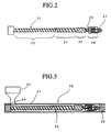
- Fig. 2 schematically shows one example of such an extruder.
- a screw 21 provided with a spiral flight has a feed portion 22, a metering portion 23, a cross-saw portion 24, a deep-screw channel portion 25, a high-shear portion 26 and an end portion 27 provided with mixing pins in this order from the hopper side.
- the length of the screw 21 is conveniently expressed by a length/diameter (L/D) ratio.
- the L/D ratio of the screw 21 is generally 20 or more. When it is less than 20, sufficient blending cannot be conducted.
- the upper limit of the L/D ratio is not particularly restricted, but it is preferably about 4.0.
- the extruder 30 comprises a cylinder 31, a screw 32 having a spiral flight on its outer surface and rotatably disposed inside the cylinder 31 concentrically therewith, a hopper 33 for supplying a thermoplastic resin, an opening 34 positioned in a side wall of the cylinder 31 near its front end and communicating with the hopper 33 for receiving the thermoplastic resin from the hopper 33, and an extrusion mechanism 35 mounted to the cylinder 31 at a downstream end thereof.
- a resin mixture based on high-density polyethylene supplied from the hopper 33 passes through the opening 34 and is fed through the extruder 30 by the screw 32.
- the resin mixture is melt-blended until it reaches the extrusion mechanism 35.
- the melt blending is well conducted by the screw 32 constituted by the above-described portions.
- the melt blending mechanism of the high-density polyethylene-based resin composition by various portions of the screw 32 will be explained below along the flow of the resin mixture.
- the screw is provided with a spiral flight and functions to conduct a first-stage melt blending while gradually compressing the resin mixture.
- the feed portion 22 is not restricted to a particular shape, but may have any shape which is usually used.
- Such a feed portion has a length (expressed by an L/D ratio) of 10 or more, particularly 12-16.
- L/D ratio is lower than 10, it is difficult to achieve sufficient melt blending of the resin mixture, and the resin mixture cannot be compressed to have a sufficiently large apparent density.
- the screw 32 is also provided with a spiral flight in this portion, to blend the resin mixture homogeneously and to meter an extrusion rate of the resin supplied from the feed portion 22 per 1 cycle of the screw 32.
- the metering portion 23 is not restricted to a particular shape, but may have any shape which is used usually. Since the screw shaft has a larger diameter in the metering portion 22 than in the feed portion 22, the height of the spiral flight is smaller in the metering portion 23 than in the feed portion 22.
- the L/D ratio of the metering portion 23 is preferably 4 or more, particularly 4-6. When the L/D ratio is lower than 4, it is difficult to perform the above-described function.
- the cross-saw portion 24 is a portion in which the resin is subjected to a melt blending action in a lateral direction. This portion is necessary because the melt blending of the resin in the feed portion 22 and the metering portion 23 is insufficient as far as the lateral melt blending action is concerned.
- the screw shaft has a slightly larger outer diameter, and flight channels are provided with pins, or the spiral flight is notched at a constant interval.
- One example of the cross-saw portion 24 is shown in Fig. 4.
- polyamide particles By conducting melt blending in a lateral direction, polyamide particles can be dispersed finely to produce a homogeneous composition, and a uniform temperature distribution can be achieved in the resin mixture.
- the L/D ratio of the cross-saw portion 24 is preferably 1 or more, particularly 1-2. When it is lower than 1, it is difficult to achieve the above-described function sufficiently.
- the resin heated in the metering portion 23 and the cross-saw portion 24 is caused to reside in the deep-screw channel portion 25 temporarily, and is cooled by a cylinder barrel of the extruder. Accordingly, the screw shaft has a smaller diameter in the deep-screw channel portion 25.
- the L/D ratio of the deep-screw channel portion 25 is preferably 0.5 or more, particularly 1-2. When it is lower than 0.5, it is difficult to achieve the above-described function sufficiently.
- the high-shear portion 26 is a portion in which the resin which has passed through the feed portion 22, the metering portion 23, the cross-saw portion 24 and the deep-screw channel portion 25 is subjected to intense shearing, so that unmolten resin portions, if any, are homogeneously blended with the other molten portion of the resin.
- the high-shear portion 26 is not restricted to a particular shape, and may be a ring type, a torpedo type, a MADDOCK type, etc. Among them, the MADDOCK type is most preferable. To apply a large shearing force and a high heat energy to the resin, there should be as small a gap as possible between an inner wall of the cylinder 31 and the high-shear portion 26. Thus, the screw shaft has a larger diameter than any other portions of the screw 32.
- MADDOCK type is shown in Fig. 5.
- the screw shaft has a larger diameter in the high-shear portion 26. Pairs of longitudinal grooves 51, 51' are provided, and adjacent longitudinal grooves 51, 51' are communicated with each other via each groove 52.
- the resin composition enter into the longitudinal groove 51, and passes through the longitudinal groove 51' via the communicating groove 52.
- the screw diameter is larger in the high-shear portion 26, the resin is given a large shearing force and a high heat energy, so that unmolten resin portions are melted and blended with the other portion (molten portion) of the resin to produce a homogeneous blend.
- the L/D ratio of the high-shear portion 26 is preferably 2 or more, particularly 2-4. When it is lower than 2, it is difficult to achieve the above-described function sufficiently.
- the resin whose unmolten resin portions are melted in the high-shear portion 26 is blended in both longitudinal and transverse directions to produce a homogeneous mixture.
- Fig. 6 One example of the end portion 27 is shown in Fig. 6.
- the screw is provided with a spiral flight 61 and mixing pins 62 in a screw channel.
- the resin mixture based on high-density polyethylene is subjected to larger melt blending in a lateral direction than in a case where the screw has a usual spiral flight without mixing pins.
- the L/D ratio of the end portion 27 is preferably 1 or more, particularly 1-2. When it is lower than 1, it is difficult to achieve the above-described function sufficiently.
- the extrusion mechanism 35 is usually communicated with a blow molding machine.
- a blow molding machine having a mandrel for producing a parison for multi-layer moldings by co-extrusion is preferably fixed to the extrusion mechanism 35.
- the cylinder temperature is appropriately controlled within the range of 170-250°C.
- the feed portion 22, the metering portion 23, the cross-saw portion 24, the deep-screw channel portion 25 and the high-shear portion 26 are controlled at 170-200°C, and the end portion 27 is controlled at 200-240°C.
- the extrusion rate of the resin blended by such an extruder can be appropriately determined depending upon the size of the extruder. For instance, in the case of an extruder having a cylinder inner diameter of 90 mm, the extrusion rate is preferably about 150-200 kg/hr. When the extrusion rate of the resin is too high, the time period during which the resin resides in the extruder is short, resulting in insufficient blending.
- the dispersed polyamide particles In a composition for the high-density polyethylene layer obtained by blending by means of the above-described extruder, the dispersed polyamide particles have as small an average particle size as 10 ⁇ m or less.
- the multi-layer plastic fuel tank thus obtained whose high-density polyethylene layer is made of a composition containing flashes and defective moldings generated in the production of the multi-layer plastic fuel tanks, shows properties such as impact resistance, which are only little deteriorated, if any.
- part or whole of the multi-layer plastic fuel tank is mixed with virgin high-density polyethylene, and the resulting mixture is melt-blended by an extruder having the above-described structure and reused for the high-density polyethylene layer of the multi-layer plastic fuel tank.
- the multi-layer plastic fuel tank obtained from such regenerated product does not suffer from the deterioration of properties such as impact resistance, etc.
- the resin based on high-density polyethylene was melt-blended by the following single-screw extruder (cylinder diameter: 90 mm):
- a multi-layer plastic fuel tank (capacity: 40 liter) of a 3-type, 5-layer structure was produced from high-density polyethylene, modified high-density polyethylene and polyamide by using a multi-layer blow molding machine (NB-60G, manufactured by The Japan Steel Works, Ltd.).
- the resulting multi-layer plastic fuel tank was pulverized by a crusher having a punching plate diameter of 8 mm.
- the pulverized multi-layer plastic fuel tank and high-density polyethylene (virgin resin) were dry-blended at a weight ratio of 50:50 to produce a resin mixture.
- Each of the above resin mixtures was melt-blended at a resin temperature shown in Table 5 at an extrusion rate of 90 kg/hr or 180 kg/hr by using an extruder of the type shown in Table 1.
- a particle size of polyamide particles was measured, and a maximum extrusion rate at which the polyamide particle size of 10 ⁇ m or less could be obtained was defined as a maximum extrusion rate capable of giving good dispersion of polyamide.
- the dispersibility of polyamide particles was evaluated as " ⁇ " when the polyamide particles had a particle size of 10 ⁇ m or less at an extrusion rate of 180 kg/hr, and "X" when the polyamide particles had a particle size exceeding 10 ⁇ m at an extrusion rate of 180 kg/hr. The results are shown in Table 1 together with the type of polyamide used.
- Parisons were produced at the maximum extrusion rate providing good dispersion of the polyamide and at half the maximum extrusion rate (1/2 maximum extrusion rate), and measured with respect to a tensile elongation and a tensile impact strength at -40°C according to a tensile test method (ASTM D638) and a tensile impact test (ASTM D1822), respectively.
- the dispersed polyamide particles had a particle size of 1 ⁇ m or less at both extrusion rates of 90 kg/hr and 180 kg/hr, and that the resin compositions produced by the method of the present invention show as good tensile elongation and tensile impact strength as those of the resin compositions produced from the virgin resin.
- the resin composition for the high-density polyethylene layer contained polyamide particles having a particle size of 10 ⁇ m or less at an extrusion rate of up to 90 kg/hr.
- the particle size of the polyamide particles was as large as 50-200 ⁇ m, and the resin composition showed reduced tensile elongation and tensile impact strength.
- Flashes and defective moldings generated in the production of multi-layer fuel tanks for the evaluation test of dispersibility of polyamide were pulverized and dry-blended with virgin high-density polyethylene at a weight ratio of 50:50, and melt-blended at a temperature shown in Table 2 using a single-screw extruder (b), (c) or (e) as a main extruder of a multi-layer blow molding machine, to produce a multi-layer plastic fuel tank (40 liter, 6 kg) having a 3-type, 5-layer structure (two high-density polyethylene layers: 3300 ⁇ m (total), two modified high-density polyethylene layers: 100 ⁇ m (total), one polyamide layer: 100 ⁇ m). The moldability of the fuel tank was evaluated. The thickness ratio was about 94:3:3.
- Example 11 was repeated to produce a multi-layer plastic fuel tank except for changing the thickness ratio of two high-density polyethylene layers, two modified high-density polyethylene layers and one polyamide layer to 60:20:20.
- the drop impact test at -40°C and the gasoline permeability test at 40°C were carried out in the same manner as in Example 11. The results are shown in Table 2.
- the multi-layer plastic fuel tank having high-density polyethylene layer produced from the resin composition according to the present invention is well moldable and has good impact strength and gas barrier properties. This is due to the fact that since fine polyamide particles are uniformly dispersed in high-density polyethylene, there is substantially no deterioration in the high-density polyethylene layer. On the other hand, the multi-layer plastic fuel tanks produced by the methods of Comparative Examples 5 and 6 were broken due to poor impact strength.
- the polyamide layer of the multi-layer plastic fuel tank is made of nylon 6-66
- the resin temperature of high-density polyethylene in the course of extruding the parison can be lowered. Accordingly, the drawdown of the parison is effectively prevented, and the molding cycle time can be shortened.
- the resulting high-density polyethylene composition contains fine polyamide particles dispersed uniformly therein, so that there is no substantial decrease in properties such as impact resistance, etc.
- a single-screw extruder provided with a screw having a special structure is used, and part or whole of the multi-layer plastic fuel tank is used as a regenerated product to be blended with virgin high-density polyethylene for the high-density polyethylene layer.
- Such multi-layer plastic fuel tank of the present invention is economically advantageous because the flashes and defective moldings inevitably generated in the course of its production can be reused.
Landscapes
- Engineering & Computer Science (AREA)
- Mechanical Engineering (AREA)
- Manufacturing & Machinery (AREA)
- Extrusion Moulding Of Plastics Or The Like (AREA)
- Blow-Moulding Or Thermoforming Of Plastics Or The Like (AREA)
- Laminated Bodies (AREA)
Description
- The present invention relates to a method of producing a multi-layer plastic fuel tank by forming its high-density polyethylene layer by reusing flashes and defective moldings of multi-layer plastic fuel tanks as regenerated products.
- Polyolefin resins are inexpensive and strong, and excellent in a weathering resistance and a chemical resistance, so that they are widely used for various containers. However, the polyolefin resins do not necessarily have sufficient gas barrier properties. Accordingly, they cannot be used for fuel tanks for gasoline, etc. in countries having strict regulations.
- In view of the above, various attempts have been made to provide thermoplastic resin compositions having excellent mechanical strength and gas barrier properties by blending polyamides such as nylons having excellent gas barrier properties with the polyolefin resins (Japanese Patent Laid-Open Nos. 54-123158, 59-232135, 62-158739, 62-241938 and 62-241941). Also, instead of blending, it was proposed to laminate polyamide layers and polyolefin resin layers to produce multi-layer plastic fuel tanks having improved gas barrier properties (Japanese Patent Laid-Open No. 55-121017 and Japanese Patent Publication No. 60-14695). In this case, since the polyolefin resin layers generally have a relatively poor bonding strength to the polyamide layers, they are laminated via modified plastic layers such as those made of polyolefin resins modified with unsaturated carboxylic acids or their derivatives. Such multi-layer moldings for fuel tanks are generally produced by forming parisons by a usual extrusion molding method and then subjecting the parisons to blow molding (Japanese Patent Laid-Open Nos. 58-220738, 62-110526).
- Japanese Patent Publication No. 60-34461 discloses a method of producing a multi-layer, blow-molded container constituted by a laminate of a polyolefin resin layer, a polyamide or saponified ethylene-vinyl acetate copolymer layer and an intermediate layer interposed therebetween, the intermediate layer being made of a modified ethylene copolymer produced by grafting 0.01-1 weight % of maleic anhydride to a copolymer of ethylene and an α-olefin having 3 or more carbon atoms and showing a crystallinity of 2-30%.
- However, the polyamide layers of the above multi-layer moldings are usually made of polyamide 6, and from the viewpoint of moldability of the polyamide layer, the temperature of the high-density polyethylene layer (main layer) should be higher than that of a single-layer plastic fuel tank made of high-density polyethylene only. As a result, there arises a problem of drawdown of a parison.
- Apart from the above, since large amounts of flashes and defective moldings are generated in the course of blow molding, it was proposed to recover those flashes and defective moldings and reuse them by mixing them with polyolefin resins (Japanese Patent Laid-Open Nos. 54-113678 and 55-91634).
- Japanese Patent Laid-Open Nos. 55-91634 discloses a multi-layer molding constituted by a laminate of (a) a polyolefin resin layer, (b) a polyamide layer obtained by melt-blending (i) a modified polymer produced by grafting maleic anhydride to an ethylene/α-olefin copolymer having a crystallinity of 1-35% and a melt index of 0.01-50 g/10 minutes (maleic anhydride content: 0.05-1 weight %) and (ii) polyamide, and (c) a modified polyolefin resin layer made of a modified polymer produced by grafting maleic anhydride to an ethylene/α-olefin copolymer having a crystallinity of 2-30% and a melt index of 0.01-50 g/10 minutes (maleic anhydride content: 0.01-1 weight %), which is interposed between the polyolefin resin layer and the polyamide layer for bonding them, the multi-layer molding suffering from only little deterioration of mechanical strength even though flashes and defective moldings of the multi-layer moldings are reused as part of starting materials.
- However, thermoplastic resin compositions having satisfactory bonding strength and impact resistance cannot necessarily be obtained simply by mixing the flashes and defective moldings of multi-layer moldings with polyolefin resins. This is due to a low compatibility between polyolefin resins and polyamides. Since the impact resistance is a particularly important property for the fuel tanks, its decrease greatly reduces the values of the fuel tanks. Although a high impact resistance can be maintained if flashes and defective moldings are not added as regenerated products, the cost reduction of materials for the fuel tanks cannot be achieved.
- In addition, when flashes and defective moldings generated in the production of multi-layer plastic fuel tanks are blended with a virgin polyolefin resin, the resin temperature should be set at 230-250°C to improve the dispersibility of polyamide. In this case, there is remarkable decrease in drawdown resistance of the parison.
- Japanese Patent Publication JP-A-1 294 748 discloses a method for processing scraps produced in molding processes for the production of polyamide-containing multi-layer plastic fuel tanks. The scraps are melt extruded at temperatures above 260°C to form pellets which are blended with virgin HDPE resin. The composition so formed can be reused as the outer layer of multi-layer plastic fuel tanks.
- An object of the present invention is to provide a method of producing a multi-layer plastic fuel tank having an excellent impact resistance by reusing flashes and defective moldings of multi-layer plastic fuel tanks and mixing them with high-density polyethylene.
- The inventors have found by blending high-density polyethylene with flashes and defective moldings of multi-layer plastic fuel tanks by using an extruder equipped with a screw having a special structure, the resulting composition can have fine polyamide particles uniformly dispersed therein, and that this composition can be used as a high-density polyethylene composition for the high density polyethylene layer of a multi-layer plastic fuel tank to improve its various properties. The present invention is based on these findings.
- Thus, a method of producing a multi-layer plastic fuel tank according to the present invention comprises a high-density polyethylene layer, a modified high-density polyethylene layer, a polyamide layer, a modified high-density polyethylene layer and a high-density polyethylene layer according to the present invention comprises the step of forming the high-density polyethylene layer from a composition obtained by blending 20-200 parts by weight of part or whole of the multi-layer plastic fuel tank as a generated product with 100 parts by weight of virgin high-density polyethylene, wherein the blending is carried out at an extrusion temperature of 200-250°C by using a single-screw extruder having an L/D ratio of 20 or more and provided with a screw constituted by a feed portion, a metering portion for metering an extrusion rate, a cross-saw portion for applying a lateral shearing force to a resin flow thereby conducting the blending of the resin, a deep-screw channel portion in which the resin resides, a high-shear portion and an end portion having mixing pins in this order from the hopper side.
-
- Fig. 1 is a partial cross-sectional view showing one example of a multi-layer structure of the multi-layer plastic fuel tank according to the present invention;
- Fig. 2 is a schematic view showing one example of a screw in a single-screw extruder used for the blending of resins for the high-density polyethylene layer in the method of the present invention;
- Fig. 3 is a partially cross-sectional view showing one example of the extruder used for the blending of resins for the high-density polyethylene layer in the method of the present invention;
- Fig. 4 is a schematic view showing one example of a cross-saw portion of the extruder;
- Fig. 5 is a schematic view showing one example of a high-shear portion of the extruder; and
- Fig. 6 is a schematic view showing one example of an end portion (mixing portion) of the extruder having mixing pins.
- The multi-layer plastic fuel tank is constituted by three types of layers: a high-density polyethylene layer, a polyamide layer and a modified high-density polyethylene layer (made of high-density polyethylene modified with unsaturated carboxylic acid or its derivatives).
- High-density polyethylene forming the high-density polyethylene layer has a density of 0.935 g/cm3 or more, and preferably has a melt index (MI, 190°C, 2.16 kg load) of 0.003-2 g/10 minutes from the aspects of a drawdown resistance, a moldability and an impact resistance. The more preferred melt index is 0.01-1 g/10 minutes. Incidentally, when the flowability of the high-density polyethylene is expressed by a high-load melt index (HLMI, 190°C, 21.6 kg load), it is preferably 70 g/10 minutes or less, more preferably 1-20 g/10 minutes.
- Polyamides forming the polyamide layer are polymers containing amide bonds (-CONH-), and they may be produced by (1) a ring-opening polymerization of lactams; (2) a condensation polymerization of amino carboxylic acids; (3) a condensation polymerization of diamines and dibasic acids. Their examples include polyamide resins formed from aliphatic, alicyclic or aromatic diamines such as hexamethylenediamine, decamethylenediamine, dodecamethylenediamine, 2,2,4- or 2,4,4-trimethylhexamethylenediamine, 1,3- or 1,4-bis (aminomethyl) cyclohexane, bis (p-aminocyclohexylmethane), m- or p-xylylenediamine, and aliphatic, alicyclic or aromatic dicarboxylic acids such as adipic acid, suberic acid, sebacic acid, cyclohexane dicarboxylic acid, terephthalic acid and isophthalic acid; polyamide resins formed from amino carboxylic acids such as 6-amino caproic acid, 11-amino undecanoic acid and 12-amino dodecanoic acid; polyamide resins formed from lactams such as ε-caprolactam and ω-dodecalactam; copolymers made of these components; and mixtures of these polyamide resins. Specifically, the polyamide resins may be polyamide 6, polyamide 66, polyamide 11, polyamide 12 and copolymers consisting of these nylons. Besides, copolymers comprising 50 weight % or more of these polyamide resins and other resins may also be used.
- The weight-average molecular weight (Mw) of the polyamide is preferably 3,000-200,000, more preferably 10,000-100,000.
- To improve the impact resistance, the polyamide may contain 5-30 weight % of a plasticizer such as ε-caprolactam, N-butylbenzene sulfonamide and octyl paraoxybenzoate. The preferred amount of the plasticizer is 10-20 weight %.
- In the preferred embodiment, the polyamide layer is made of a polyamide copolymer comprising polyamide 6 and polyamide 66 (polyamide 6-66).
- The polyamide 6 is generally represented by the following formula (1):

- The polyamide 66 is generally represented by the following formula (2):

- The content of the polyamide 6 is 60-90 weight %, preferably 70-80 weight %, and the content of the polyamide 66 is 40-10 weight %, preferably 30-20 weight % in the polyamide copolymer. When the content of the polyamide 6 is lower than 60 weight % (when the content of the polyamide 66 exceeds 40 weight %), the multi-layer plastic fuel tank shows poor gas barrier properties. On the other hand, when the content of the polyamide 6 exceeds 90 weight % (when the content of the polyamide 66 is lower than 10 weight %), the multi-layer plastic fuel tank does not show an improved impact resistance.
- The above polyamide 6-66 can be produced, for instance, by copolymerizing hexamethylene diamine and adipic acid in the presence of ε-caprolactam.
- The polyamide 6-66 has a relative viscosity (JIS K6810) of 3-6.5, particularly 4-6.
- In the further preferred embodiment of the present invention, the polyamide 6-66 may be blended with a modified olefinic elastomer.
- The modified olefinic elastomer is an olefinic elastomer modified with an unsaturated carboxylic acid or its derivatives. The unsaturated carboxylic acid or its derivatives are monocarboxylic acids such as acrylic acid and methacrylic acid; dicarboxylic acids such as maleic acid, fumaric acid and itaconic acid; dicarboxylic anhydrides such as maleic anhydride, itaconic anhydride and endomethylenetetrahydrophthalic anhydride (hymic anhydride), and particularly maleic anhydride and endomethylenetetrahydrophthalic anhydride are preferable.
- The olefinic elastomers to be modified with graft monomers are copolymer rubbers comprising two or more α-olefins comprising ethylene, propylene, 1-butene, 1-hexene and 4-methyl-1-pentene. Among them, an ethylene-propylene copolymer rubber (EPR) and an ethylene-butene copolymer rubber (EBR) are particularly preferable.
- The ethylene-propylene copolymer rubber (EPR) used in the present invention preferably comprises 10-90 mol % of ethylene, and 90-10 mol % of propylene. The more preferred range is 20-80 mol % for the ethylene and 80-20 mol % for the propylene. The ethylene-propylene copolymer rubber (EPR) has a Mooney viscosity ML1+4 (100°C) of 1-120, preferably 5-100.
- The ethylene-butene copolymer rubber (EBR) used in the present invention preferably comprises 10-90 mol % of ethylene, and 90-10 mol % of butene. The more preferred range is 20-80 mol % for the ethylene and 80-20 mol % for the butene. The ethylene-butene copolymer rubber (EBR) has a Mooney viscosity ML1+4 (100°C) of 1-120, preferably 5-100.
- The ethylene-propylene copolymer rubber (EPR) and the ethylene-butene copolymer rubber (EBR) may further contain other α-olefins such as 4-methyl-1-pentene in such an amount that they do not deteriorate the properties of EPR or EBR.
- The proportion of the unsaturated carboxylic acid or its derivatives in the modified olefinic elastomer is 1.0 x 10⁻⁵ to 6.0 x 10⁻⁵ mol/g, preferably 2.0 x 10⁻⁵ to 5.0 x 10⁻⁵ mol/g. Specifically, in the case of maleic anhydride, its content is 0.005-5 weight %, preferably 0.01-3 weight %, and in the case of hymic anhydride (endomethylenetetrahydrophthalic anhydride), its content is 0.015-4 weight %, preferably 0.15-1.5 weight %. If the amounts of maleic anhydride and hymic anhydride are smaller than the lower limits of the above ranges, sufficient compatibility of the modified olefinic elastomer with polyamide cannot be achieved. On the other hand, if their amounts exceed the upper limits of the above ranges, the modified olefinic elastomer cannot be sufficiently dispersed in the polyamide.
- Such modified olefinic elastomers can be produced by a solution method or a melt blending method.
- The modified olefinic elastomer is blended with the polyamide 6-66 preferably in an amount of 30 weight % or less based on 100 weight % of the polyamide 6-66 + the modified olefinic elastomer. When the amount of the modified olefinic elastomer exceeds 30 weight %, the multi-layer plastic fuel tank shows reduced gas barrier properties.
- Modified high-density polyethylene forming the modified high-density polyethylene layer is high-density polyethylene modified with an unsaturated carboxylic acid or its derivatives. The unsaturated carboxylic acid or its derivatives may be the same as used for modifying the olefinic elastomer. The high-density polyethylene to be modified with the unsaturated carboxylic acid or its derivatives may be the same as used for the high-density polyethylene layer.
- The proportion of the unsaturated carboxylic acid or its derivatives in the modified high-density polyethylene layer is preferably 0.005-5 weight %. Specifically, in the case of maleic anhydride, its content is preferably 0.01-3 weight %, more preferably 0.1-1 weight %, and in the case of hymic anhydride (endomethylenetetrahydrophthalic anhydride), its content is 0.015-4 weight %, more preferably 0.15-1.5 weight %. If the amounts of maleic anhydride and hymic anhydride are smaller than the lower limits of the above preferred ranges, sufficient bonding cannot be achieved between the polyamide layer and the modified high-density polyethylene layer. On the other hand, if their amounts exceed the upper limits of the above preferred ranges, a bonding strength decreases between the modified high-density polyethylene layer and the high-density polyethylene layer.
- Such modified high-density polyethylene can be produced by a solution method or a melt blending method.
- Incidentally, each of the above layers may contain other additives such as fillers, thermostabilizers, anti-oxidants, photostabilizers, flame retarders, plasticizers, anti-static agents, parting agents, foaming agents and nucleating agents to improve their properties.
- The multi-layer plastic fuel tank made of the above resins has a multi-layer structure in which adjacent high-density polyethylene layer and polyamide layer are bonded to each other via a modified high-density polyethylene layer. A typical example of such multi-layer structure is shown in Fig. 1, which comprises outer and inner high-
density polyethylene layers central polyamide layer 2 and intermediate modified high-density polyethylene layers density polyethylene layer 1 andpolyamide layer 2. - The thickness proportions of the two high-
density polyethylene layers density polyethylene layers polyamide layer 2 are preferably 99-60 : 0.5-20 : 0.5-20. When the total thickness of the two high-density polyethylene layers is smaller than 60% of the thickness of the multi-layer plastic fuel tank, the multi-layer plastic fuel tank does not have a sufficient strength. When the polyamide layer is thinner than 0.5% of the thickness of the multi-layer plastic fuel tank, the fuel tank does not have sufficient gas barrier properties. And when each modified high-density polyethylene layer is thinner than 0.25% (0.5% x 1/2) of the thickness of the multi-layer plastic fuel tank, a sufficient bonding strength cannot be achieved between the high-density polyethylene layer and the polyamide layer. - The thickness of each layer of the multi-layer plastic fuel tank may be determined depending upon the impact resistance and gas barrier properties required as the fuel tank. Specifically, in the case of a gasoline tank, the high-density polyethylene layer has a thickness of 1.5-5 mm, the polyamide layer has a thickness of 20-500 µm, and the modified high-density polyethylene layer has a thickness of 20-500 µm. Incidentally, if there are two or more layers in each category of the layers, it should be noted that the above thickness means a total thickness.
- In the present invention, part or whole of the multi-layer plastic fuel tank is reused as a regenerated high-density polyethylene composition for the high-density polyethylene layer.
- A proportion of the regenerated product (obtained from part or whole of the multi-layer plastic fuel tank) to be blended with virgin high-density polyethylene may differ depending upon the thickness of each layer, but it is generally 20-200 parts by weight per 100 parts by weight of the virgin high-density polyethylene. When the proportion of the regenerated product is lower than 20 parts by weight, sufficient cost reduction by using the regenerated product cannot be achieved. On the other hand, when it exceeds 200 parts by weight, the percentage of polyamide is too high in the high-density polyethylene layer, resulting in the decrease in an impact resistance. The preferred proportion of the regenerated product in the high-density polyethylene layer is 20-150 parts by weight.
- The multi-layer plastic fuel tank can be produced, for instance, by extruding a resin for each layer from an extruder, forming a cylindrical parison having the above layer structure by a usual co-extrusion method, setting this parison in a blow molding die cavity having a desired shape and subjecting it to blow molding.
- In the process of extruding a parison, the extrusion temperature of the high-density polyethylene layer as a main layer is lower than the usual extrusion temperature. Namely, although the extrusion temperature of high-density polyethylene is usually 230-250°C, the extrusion temperature of the high-density polyethylene layer is determined within the range of 200-230°C, by the melting temperature of the polyamide 6-66. For instance, in a case where a weight ratio of the polyamide 6 (a) to the polyamide 66 (b) is 90:10, the resin for the high-density polyethylene layer is extruded at 220-230°C. In the case of (a)/(b) = 70:30, the extrusion temperature is 210-220°C. Also, in the case of (a)/(b) = 60:40, the extrusion temperature is 200-210°C. This low extrusion temperature serves not only to prevent the drawdown of a parison but also to shorten a molding cycle time.
- In this embodiment, since the polyamide layer of the multi-layer plastic fuel tank is made of the polyamide 6-66, the resin temperature of the high-density polyethylene can be reduced in the formation of its parison. As a result, the drawdown of the parison can be prevented. The reason therefor is not necessarily clear, but it may be presumed that since the polyamide 6-66 has lower melting point and crystallization temperature, and better heat resistance and a moldability as compared with polyamide 6 as a homopolymer, the co-extrusion of the polyamide 6-66, the high-density polyethylene and the modified high-density polyethylene can be conducted at a lower temperature.
- In the method according to the preferred embodiment of the present invention, a single-screw extruder having an L/D ratio of 20 or more and provided with a screw constituted by a feed portion, a metering portion for metering an extrusion rate, a cross-saw portion for applying a lateral shearing force to a resin flow thereby conducting the blending of the resin, a deep-screw channel portion in which the resin resides, a high-shear portion and an end portion having mixing pins in this order from the hopper side is used. Fig. 2 schematically shows one example of such an extruder.
- In Fig. 2, a
screw 21 provided with a spiral flight has afeed portion 22, ametering portion 23, across-saw portion 24, a deep-screw channel portion 25, a high-shear portion 26 and anend portion 27 provided with mixing pins in this order from the hopper side. - The length of the
screw 21 is conveniently expressed by a length/diameter (L/D) ratio. The L/D ratio of thescrew 21 is generally 20 or more. When it is less than 20, sufficient blending cannot be conducted. The upper limit of the L/D ratio is not particularly restricted, but it is preferably about 4.0. - The single-screw extruder having the above-described screw has a structure shown, for instance, by Fig. 3. In Fig. 3, the
extruder 30 comprises acylinder 31, ascrew 32 having a spiral flight on its outer surface and rotatably disposed inside thecylinder 31 concentrically therewith, ahopper 33 for supplying a thermoplastic resin, anopening 34 positioned in a side wall of thecylinder 31 near its front end and communicating with thehopper 33 for receiving the thermoplastic resin from thehopper 33, and anextrusion mechanism 35 mounted to thecylinder 31 at a downstream end thereof. - In such an extruder, a resin mixture based on high-density polyethylene supplied from the
hopper 33 passes through theopening 34 and is fed through theextruder 30 by thescrew 32. During passing through thecylinder 31, the resin mixture is melt-blended until it reaches theextrusion mechanism 35. The melt blending is well conducted by thescrew 32 constituted by the above-described portions. The melt blending mechanism of the high-density polyethylene-based resin composition by various portions of thescrew 32 will be explained below along the flow of the resin mixture. - In the
feed portion 22, the screw is provided with a spiral flight and functions to conduct a first-stage melt blending while gradually compressing the resin mixture. Thefeed portion 22 is not restricted to a particular shape, but may have any shape which is usually used. - Such a feed portion has a length (expressed by an L/D ratio) of 10 or more, particularly 12-16. When the L/D ratio is lower than 10, it is difficult to achieve sufficient melt blending of the resin mixture, and the resin mixture cannot be compressed to have a sufficiently large apparent density.
- The
screw 32 is also provided with a spiral flight in this portion, to blend the resin mixture homogeneously and to meter an extrusion rate of the resin supplied from thefeed portion 22 per 1 cycle of thescrew 32. Themetering portion 23 is not restricted to a particular shape, but may have any shape which is used usually. Since the screw shaft has a larger diameter in themetering portion 22 than in thefeed portion 22, the height of the spiral flight is smaller in themetering portion 23 than in thefeed portion 22. - The L/D ratio of the
metering portion 23 is preferably 4 or more, particularly 4-6. When the L/D ratio is lower than 4, it is difficult to perform the above-described function. - The
cross-saw portion 24 is a portion in which the resin is subjected to a melt blending action in a lateral direction. This portion is necessary because the melt blending of the resin in thefeed portion 22 and themetering portion 23 is insufficient as far as the lateral melt blending action is concerned. For achieving the lateral melt blending action, the screw shaft has a slightly larger outer diameter, and flight channels are provided with pins, or the spiral flight is notched at a constant interval. One example of thecross-saw portion 24 is shown in Fig. 4. - In Fig. 4, the spiral flight of the screw is notched at a constant interval. By these
notches 41, the resin mixture is subjected to much stronger melt blending in a lateral direction than in a case where a usual spiral flight without notches is used. - By conducting melt blending in a lateral direction, polyamide particles can be dispersed finely to produce a homogeneous composition, and a uniform temperature distribution can be achieved in the resin mixture.
- The L/D ratio of the
cross-saw portion 24 is preferably 1 or more, particularly 1-2. When it is lower than 1, it is difficult to achieve the above-described function sufficiently. - The resin heated in the
metering portion 23 and thecross-saw portion 24 is caused to reside in the deep-screw channel portion 25 temporarily, and is cooled by a cylinder barrel of the extruder. Accordingly, the screw shaft has a smaller diameter in the deep-screw channel portion 25. - The L/D ratio of the deep-
screw channel portion 25 is preferably 0.5 or more, particularly 1-2. When it is lower than 0.5, it is difficult to achieve the above-described function sufficiently. - The high-
shear portion 26 is a portion in which the resin which has passed through thefeed portion 22, themetering portion 23, thecross-saw portion 24 and the deep-screw channel portion 25 is subjected to intense shearing, so that unmolten resin portions, if any, are homogeneously blended with the other molten portion of the resin. - The high-
shear portion 26 is not restricted to a particular shape, and may be a ring type, a torpedo type, a MADDOCK type, etc. Among them, the MADDOCK type is most preferable. To apply a large shearing force and a high heat energy to the resin, there should be as small a gap as possible between an inner wall of thecylinder 31 and the high-shear portion 26. Thus, the screw shaft has a larger diameter than any other portions of thescrew 32. One example of such a high-shear portion (MADDOCK type) is shown in Fig. 5. - In Fig. 5, the screw shaft has a larger diameter in the high-
shear portion 26. Pairs oflongitudinal grooves 51, 51' are provided, and adjacentlongitudinal grooves 51, 51' are communicated with each other via eachgroove 52. - The resin composition enter into the
longitudinal groove 51, and passes through the longitudinal groove 51' via the communicatinggroove 52. In this case, since the screw diameter is larger in the high-shear portion 26, the resin is given a large shearing force and a high heat energy, so that unmolten resin portions are melted and blended with the other portion (molten portion) of the resin to produce a homogeneous blend. - The L/D ratio of the high-
shear portion 26 is preferably 2 or more, particularly 2-4. When it is lower than 2, it is difficult to achieve the above-described function sufficiently. - In the
end portion 27, the resin whose unmolten resin portions are melted in the high-shear portion 26 is blended in both longitudinal and transverse directions to produce a homogeneous mixture. - One example of the
end portion 27 is shown in Fig. 6. In Fig. 6, the screw is provided with aspiral flight 61 and mixingpins 62 in a screw channel. By these mixingpins 62, the resin mixture based on high-density polyethylene is subjected to larger melt blending in a lateral direction than in a case where the screw has a usual spiral flight without mixing pins. - By strongly blending the resin in both longitudinal and lateral directions by the
end portion 27, a homogeneous molten resin is obtained with a uniform temperature distribution, and fed to anextrusion mechanism 35. - The L/D ratio of the
end portion 27 is preferably 1 or more, particularly 1-2. When it is lower than 1, it is difficult to achieve the above-described function sufficiently. - Incidentally, the
extrusion mechanism 35 is usually communicated with a blow molding machine. In the present invention, a blow molding machine having a mandrel for producing a parison for multi-layer moldings by co-extrusion is preferably fixed to theextrusion mechanism 35. - In the extruder provided with the screw having such a structure, the cylinder temperature is appropriately controlled within the range of 170-250°C. Specifically, the
feed portion 22, themetering portion 23, thecross-saw portion 24, the deep-screw channel portion 25 and the high-shear portion 26 are controlled at 170-200°C, and theend portion 27 is controlled at 200-240°C. - The extrusion rate of the resin blended by such an extruder can be appropriately determined depending upon the size of the extruder. For instance, in the case of an extruder having a cylinder inner diameter of 90 mm, the extrusion rate is preferably about 150-200 kg/hr. When the extrusion rate of the resin is too high, the time period during which the resin resides in the extruder is short, resulting in insufficient blending.
- In a composition for the high-density polyethylene layer obtained by blending by means of the above-described extruder, the dispersed polyamide particles have as small an average particle size as 10 µm or less.
- In a case where flashes and defective moldings generated in the blow molding of parisons for multi-layer plastic fuel tanks are blended with virgin high-density polyethylene for the high-density polyethylene layer of the multi-layer plastic fuel tank, good dispersion of polyamide in the high-density polyethylene matrix can be achieved at a lower melt blending temperature than the conventional one, because the polyamide 6-66 has a lower melting point than that of the polyamide 6.
- Accordingly, the multi-layer plastic fuel tank thus obtained, whose high-density polyethylene layer is made of a composition containing flashes and defective moldings generated in the production of the multi-layer plastic fuel tanks, shows properties such as impact resistance, which are only little deteriorated, if any.
- In this embodiment, part or whole of the multi-layer plastic fuel tank is mixed with virgin high-density polyethylene, and the resulting mixture is melt-blended by an extruder having the above-described structure and reused for the high-density polyethylene layer of the multi-layer plastic fuel tank. The multi-layer plastic fuel tank obtained from such regenerated product does not suffer from the deterioration of properties such as impact resistance, etc. This is due to the fact that fine particles of polyamide can be well dispersed in a composition for the high-density polyethylene layer by synergistic effects of each portion of the extruder used in the present invention, in which the virgin high-density polyethylene and the regenerated product are blended in the feed portion, metered in the metering portion, subjected to melt blending in the direction lateral to the resin flow in the cross-saw portion, and then subjected to melting of the unmolten resin portions and blending in the high-shear portion in both longitudinal and lateral directions.
- The present invention will be explained in further detail by way of the following Examples. Incidentally, starting materials (high-density polyethylene, modified high-density polyethylene, modified olefinic elastomer and polyamide) used are as follows:
-
- HDPE
- [Melt index (MI, 190°C, 2.16 kg load): 0.03 g/10 minutes, high-load melt index (HLMI, 190°C, 21.6 kg load): 5.5 g/10 minutes, density: 0.945 g/m3, weight-average molecular weight (Mw): 20 x 104]
-
- CMPE
- [Melt index (MI, 190°C, 2.16 kg load): 0.3 g/10 minutes, maleic anhydride graft ratio: 0.4 weight %, density: 0.953 g/m3, weight-average molecular weight (Mw): 12 x 104]
-
- CMEBR
- Modified ethylene-butene copolymer rubber [ethylene-butene copolymer rubber (ethylene content: 50 weight %) grafted with 0.4 weight % of maleic anhydride, melt index (MI, 190°C, 2.16 kg load): 0.3 g/10 minutes]
-
- (1) Polyamide 6
- PA-1
- [Nylon 6, relative viscosity: 4]
- PA-2
- [Nylon 6, relative viscosity: 4.2]
- PA-3
- [Nylon 6, relative viscosity: 6.0]
- (2) Polyamide 6-66
- CPA-1
- [Nylon 6 : Polyamide 66 = 90:10, relative viscosity: 4]
- CPA-2
- [Nylon 6 : Polyamide 66 = 70:30, relative viscosity: 4]
- CPA-3
- [Nylon 6 : Polyamide 66 = 50:50, relative viscosity: 4]
- CPA-4
- [Nylon 6 : Polyamide 66 = 96:4, relative viscosity: 4]
- (3) Polyamide 6-12
- CPA-5
- [Nylon 6 : Polyamide 12 = 70:30, relative viscosity: 4]
- (4) Polyamide 6-66/modified olefinic elastomer
- CPA-B1
- [Blend of CPA-2 and CMEBR, CPA-2:CMEBR = 90:10]
- CPA-B2
- [Blend of CPA-2 and CMEBR, CPA-2:CMEBR = 70:30]
- The resin based on high-density polyethylene was melt-blended by the following single-screw extruder (cylinder diameter: 90 mm):
- (a) L/D = 30, special screw having a structure shown in Fig. 2.
- (b) L/D = 32, special screw having a structure shown in Fig. 2.
- (c) L/D = 24, special screw having a structure shown in Fig. 2.
- (d) L/D = 28, special screw having a structure shown in Fig. 2.
- (e) L/D = 24, full-flighted screw.
- (f) L/D = 28, full-flighted screw.
- A multi-layer plastic fuel tank (capacity: 40 liter) of a 3-type, 5-layer structure was produced from high-density polyethylene, modified high-density polyethylene and polyamide by using a multi-layer blow molding machine (NB-60G, manufactured by The Japan Steel Works, Ltd.). The resulting multi-layer plastic fuel tank was pulverized by a crusher having a punching plate diameter of 8 mm.
- The pulverized multi-layer plastic fuel tank and high-density polyethylene (virgin resin) were dry-blended at a weight ratio of 50:50 to produce a resin mixture.
- Each of the above resin mixtures was melt-blended at a resin temperature shown in Table 5 at an extrusion rate of 90 kg/hr or 180 kg/hr by using an extruder of the type shown in Table 1.
- With respect to a parison thus obtained, a particle size of polyamide particles was measured, and a maximum extrusion rate at which the polyamide particle size of 10 µm or less could be obtained was defined as a maximum extrusion rate capable of giving good dispersion of polyamide. The dispersibility of polyamide particles was evaluated as " ○ " when the polyamide particles had a particle size of 10 µm or less at an extrusion rate of 180 kg/hr, and "X" when the polyamide particles had a particle size exceeding 10 µm at an extrusion rate of 180 kg/hr. The results are shown in Table 1 together with the type of polyamide used.
- Parisons were produced at the maximum extrusion rate providing good dispersion of the polyamide and at half the maximum extrusion rate (1/2 maximum extrusion rate), and measured with respect to a tensile elongation and a tensile impact strength at -40°C according to a tensile test method (ASTM D638) and a tensile impact test (ASTM D1822), respectively.
- The measured values of these properties were compared with those of parisons produced from virgin resins under the same conditions as above. The results are shown in Table 1.
-


- It is clear from Table 1 that in the resin compositions for the high-density polyethylene layers produced according to the method of the present invention, the dispersed polyamide particles had a particle size of 1 µm or less at both extrusion rates of 90 kg/hr and 180 kg/hr, and that the resin compositions produced by the method of the present invention show as good tensile elongation and tensile impact strength as those of the resin compositions produced from the virgin resin.
- In Comparative Examples 1 - 4, in which a usual single-screw extruder was used, the resin composition for the high-density polyethylene layer contained polyamide particles having a particle size of 10 µm or less at an extrusion rate of up to 90 kg/hr. However, at 180 kg/hr, the particle size of the polyamide particles was as large as 50-200 µm, and the resin composition showed reduced tensile elongation and tensile impact strength.
- Flashes and defective moldings generated in the production of multi-layer fuel tanks for the evaluation test of dispersibility of polyamide were pulverized and dry-blended with virgin high-density polyethylene at a weight ratio of 50:50, and melt-blended at a temperature shown in Table 2 using a single-screw extruder (b), (c) or (e) as a main extruder of a multi-layer blow molding machine, to produce a multi-layer plastic fuel tank (40 liter, 6 kg) having a 3-type, 5-layer structure (two high-density polyethylene layers: 3300 µm (total), two modified high-density polyethylene layers: 100 µm (total), one polyamide layer: 100 µm). The moldability of the fuel tank was evaluated. The thickness ratio was about 94:3:3.
- Each fuel tank was subjected to a drop impact test at -40°C and a gasoline permeability test at 40°C. The results are shown in Table 2 together with the multi-layer structure of the fuel tank.
- Example 11 was repeated to produce a multi-layer plastic fuel tank except for changing the thickness ratio of two high-density polyethylene layers, two modified high-density polyethylene layers and one polyamide layer to 60:20:20. The drop impact test at -40°C and the gasoline permeability test at 40°C were carried out in the same manner as in Example 11. The results are shown in Table 2.


- It is clear from Table 2 that the multi-layer plastic fuel tank having high-density polyethylene layer produced from the resin composition according to the present invention is well moldable and has good impact strength and gas barrier properties. This is due to the fact that since fine polyamide particles are uniformly dispersed in high-density polyethylene, there is substantially no deterioration in the high-density polyethylene layer. On the other hand, the multi-layer plastic fuel tanks produced by the methods of Comparative Examples 5 and 6 were broken due to poor impact strength.
- As described above, when the polyamide layer of the multi-layer plastic fuel tank is made of nylon 6-66, the resin temperature of high-density polyethylene in the course of extruding the parison can be lowered. Accordingly, the drawdown of the parison is effectively prevented, and the molding cycle time can be shortened.
- Also, in a case where regenerated products of this multi-layer plastic fuel tank are blended with virgin high-density polyethylene to produce a composition for the high-density polyethylene layer of the multi-layer plastic fuel tank, the resulting high-density polyethylene composition contains fine polyamide particles dispersed uniformly therein, so that there is no substantial decrease in properties such as impact resistance, etc. This is because in the method of producing a multi-layer plastic fuel tank according to the present invention, a single-screw extruder provided with a screw having a special structure is used, and part or whole of the multi-layer plastic fuel tank is used as a regenerated product to be blended with virgin high-density polyethylene for the high-density polyethylene layer.
- Such multi-layer plastic fuel tank of the present invention is economically advantageous because the flashes and defective moldings inevitably generated in the course of its production can be reused.
Claims (3)
- A method of producing a multi-layer plastic fuel tank comprising a high-density polyethylene layer, a modified high-density polyethylene layer, a polyamide layer, a modified high-density polyethylene layer and a high-density polyethylene layer, comprising the step of forming said high-density polyethylene layer from a composition obtained by blending 20-200 parts by weight of part or whole of said multi-layer plastic fuel tank as a regenerated product with 100 parts by weight of virgin high-density polyethylene, wherein said blending is carried out at an extrusion temperature of 200-250°C by using a single-screw extruder having an L/D ratio of 20 or more and provided with a screw constituted by a feed portion, a metering portion for metering an extrusion rate, a cross-saw portion for applying a laterial shearing force to a resin flow thereby conducting the blending of the resin, a deep-screw channel portion in which said resin resides, a high-shear portion and an end portion having mixing pins in this order from the hopper side.
- The method of producing a multi-layer plastic fuel tank according to Claim 1, wherein said high-density polyethylene layer, said modified high-density polyethylene layer and said polyamide layer have a thickness ratio of 99-60 : 0.5-20 : 0.5-20.
- The method of producing a multi-layer plastic fuel tank according to Claim 1 or 2, wherein the L/D ratio of said single-screw extruder is 10 or more in said feed portion, 4 or more in said metering portion, 1 or more in said cross-saw portion, 0.5 or more in said deep-screw channel portion, 2 or more in said high-shear portion and 1 or more in said end portion having mixing pins.
Applications Claiming Priority (5)
| Application Number | Priority Date | Filing Date | Title |
|---|---|---|---|
| JP2157055A JP2866710B2 (en) | 1990-06-15 | 1990-06-15 | Method for manufacturing multilayer plastic fuel tank |
| JP15705690A JP2898359B2 (en) | 1990-06-15 | 1990-06-15 | Multi-layer plastic fuel tank |
| JP157056/90 | 1990-06-15 | ||
| JP157055/90 | 1990-06-15 | ||
| EP19910305212 EP0461836B1 (en) | 1990-06-15 | 1991-06-10 | Multi-layer plastic fuel tank |
Related Parent Applications (1)
| Application Number | Title | Priority Date | Filing Date |
|---|---|---|---|
| EP91305212.2 Division | 1991-06-10 |
Publications (2)
| Publication Number | Publication Date |
|---|---|
| EP0619169A1 EP0619169A1 (en) | 1994-10-12 |
| EP0619169B1 true EP0619169B1 (en) | 1996-09-18 |
Family
ID=26484634
Family Applications (2)
| Application Number | Title | Priority Date | Filing Date |
|---|---|---|---|
| EP19910305212 Expired - Lifetime EP0461836B1 (en) | 1990-06-15 | 1991-06-10 | Multi-layer plastic fuel tank |
| EP19940201519 Expired - Lifetime EP0619169B1 (en) | 1990-06-15 | 1991-06-10 | Method of producing multi-layer plastic fuel tank |
Family Applications Before (1)
| Application Number | Title | Priority Date | Filing Date |
|---|---|---|---|
| EP19910305212 Expired - Lifetime EP0461836B1 (en) | 1990-06-15 | 1991-06-10 | Multi-layer plastic fuel tank |
Country Status (3)
| Country | Link |
|---|---|
| US (1) | US5384172A (en) |
| EP (2) | EP0461836B1 (en) |
| DE (2) | DE69122274T2 (en) |
Families Citing this family (36)
| Publication number | Priority date | Publication date | Assignee | Title |
|---|---|---|---|---|
| IT1228464B (en) * | 1989-02-23 | 1991-06-19 | Montedipe Spa | WATERPROOF VAPOR CONTAINERS AND PROCESS FOR THEIR PRODUCTION. |
| US5443874A (en) * | 1993-05-24 | 1995-08-22 | Mitsubishi Petrochemical Co., Ltd. | Hollow multi-layer molding |
| DE69409318T2 (en) * | 1993-09-27 | 1998-11-12 | Mitsubishi Chem Corp | Ethylene polymer and fuel tank containing it |
| DE4337491A1 (en) * | 1993-11-03 | 1995-05-04 | Kautex Werke Gmbh | Container manufactured using the co-extrusion blow molding process |
| FR2720142B1 (en) * | 1994-05-20 | 1996-06-28 | Inst Francais Du Petrole | Light PA-12-carbon structure for the storage of pressurized fluids. |
| US5776842A (en) | 1994-06-23 | 1998-07-07 | Cellresin Technologies, Llc | Cellulosic web with a contaminant barrier or trap |
| US5928745A (en) * | 1994-06-23 | 1999-07-27 | Cellresin Technologies, Llc | Thermoplastic fuel tank having reduced fuel vapor emissions |
| US5985772A (en) | 1994-06-23 | 1999-11-16 | Cellresin Technologies, Llc | Packaging system comprising cellulosic web with a permeant barrier or contaminant trap |
| US5492947A (en) | 1994-06-23 | 1996-02-20 | Aspen Research Corporation | Barrier material comprising a thermoplastic and a compatible cyclodextrin derivative |
| IT1267607B1 (en) * | 1994-12-23 | 1997-02-07 | Europlastica S R L | PERFECTED PROCEDURE FOR THE REUSE OF URBAN SOLID WASTE |
| US5882565A (en) | 1995-12-11 | 1999-03-16 | Cellresin Technologies, Llc | Barrier material comprising a thermoplastic and a compatible cyclodextrin derivative |
| CA2216492C (en) * | 1996-10-03 | 2006-08-22 | Hiromi Shigemoto | Multilayer plastic container |
| US6716385B2 (en) | 1997-06-24 | 2004-04-06 | Japan Polyolefins Co., Ltd. | Ethylene (co) polymers, and laminate and hollow molding made by using the same |
| US5928743A (en) * | 1997-07-24 | 1999-07-27 | Purepak Technology Corporation | Pressurized gas vessel having internal chemical surface |
| WO2000051907A1 (en) * | 1999-03-04 | 2000-09-08 | Kuraray Co. Ltd. | Fuel container |
| EP1063115A1 (en) * | 1999-06-25 | 2000-12-27 | Fina Research S.A. | Automobile fuel tank |
| IL132735A0 (en) * | 1999-11-04 | 2001-03-19 | Raviv Prec Injection Molding | Fuel tank and a method for fitting accessories thereto |
| US6737131B1 (en) * | 1999-11-12 | 2004-05-18 | Cerowa, Inc. | Non-flammable hazardous fluid tanks |
| EP1108598A3 (en) * | 1999-12-18 | 2003-10-15 | Delphi Technologies, Inc. | Permeation barrier fuel tank |
| JP2001287269A (en) * | 2000-04-07 | 2001-10-16 | Kyosan Denki Kk | Bonding structure of resin part |
| US6550811B1 (en) * | 2000-06-30 | 2003-04-22 | Caterpillar Inc | Dual fuel tank system for an earthmoving vehicle |
| DE10054876C2 (en) * | 2000-11-06 | 2002-11-07 | Sig Kautex Gmbh & Co Kg | Double-walled fuel tank made of plastic |
| US7089952B2 (en) | 2001-03-16 | 2006-08-15 | Ube Industries, Ltd. | Fuel parts and process for producing the same |
| WO2005019341A1 (en) * | 2003-08-18 | 2005-03-03 | Chevron Phillips Chemical Company Lp | Polyphenylene sulfide composition and application |
| US7493894B2 (en) * | 2004-02-13 | 2009-02-24 | Kelch Corporation | Tank assembly and components |
| FR2866828B1 (en) * | 2004-02-26 | 2006-07-07 | Inergy Automotive Systems Res | BASIC PLASTIC LAYER COMPRISING NODULES OF BARRIER PLASTIC MATERIAL |
| US20080132636A1 (en) * | 2004-06-03 | 2008-06-05 | Gilbert Ross | Nylon monofilaments and process for preparing nylon monofilaments for the production of spiral fabrics and seam wires |
| US20070160802A1 (en) * | 2005-12-20 | 2007-07-12 | Olivier Rozant | Controlled compounding of thermoplastic polymer composition with barrier properties |
| EP1850058A1 (en) * | 2006-04-25 | 2007-10-31 | Inergy Automotive Systems Research (SA) | Storage tank |
| AU2007251935B2 (en) * | 2006-05-18 | 2011-10-06 | Mauser-Werke Gmbh | Multilayer plastic container |
| JP5123495B2 (en) * | 2006-06-14 | 2013-01-23 | 帝人ファイバー株式会社 | Membrane material for gas holder and gas holder using the same |
| US20080021156A1 (en) * | 2006-07-21 | 2008-01-24 | Thierry Arpin | Controlled compounding of thermoplastic polymer composition with barrier properties |
| US9050889B2 (en) * | 2009-09-18 | 2015-06-09 | Ti Automotive Technology Center Gmbh | Fuel tank support |
| US20150202819A1 (en) * | 2014-01-17 | 2015-07-23 | Fts Co., Ltd. | Blow-molding mold |
| DE102016216446A1 (en) | 2016-08-31 | 2018-03-01 | Kautex Textron Gmbh & Co. Kg | Plastic molding of an extruded multi-layer composite and fuel tank made of an extruded multi-layer composite |
| US20200282599A1 (en) * | 2019-03-04 | 2020-09-10 | Integrated Composite Products, Inc. | Screw designs for use when molding products that include sheer sensitive materials |
Family Cites Families (18)
| Publication number | Priority date | Publication date | Assignee | Title |
|---|---|---|---|---|
| US3423231A (en) * | 1965-05-20 | 1969-01-21 | Ethyl Corp | Multilayer polymeric film |
| US3988499A (en) * | 1975-01-20 | 1976-10-26 | Reynolds Thomas D | Storage bag and method for using same |
| DE2538892B2 (en) * | 1975-09-02 | 1979-09-27 | Basf Ag, 6700 Ludwigshafen | Process for the production of transparent composite films |
| JPS6014695B2 (en) * | 1979-03-06 | 1985-04-15 | イ−・アイ・デユポン・デ・ニモアス・アンド・カンパニ− | Layered molded product and its manufacturing method |
| JPS55142650A (en) * | 1979-04-23 | 1980-11-07 | Toppan Printing Co Ltd | Multilayer vessel |
| JPS56120345A (en) * | 1980-02-27 | 1981-09-21 | Sekisui Chemical Co Ltd | Threeelayer vessel |
| US4588648A (en) * | 1981-02-20 | 1986-05-13 | American Can Company | Multiple layer plastic film having polypropylene adhered to nylon |
| DE3242708A1 (en) * | 1981-11-21 | 1983-06-16 | Barmag Barmer Maschinenfabrik Ag, 5630 Remscheid | Single shaft screw extruder |
| JPS5892545A (en) * | 1981-11-30 | 1983-06-01 | Toshiba Mach Co Ltd | Extruder for molding thermoplastic resin |
| US4481262A (en) * | 1982-02-19 | 1984-11-06 | Chemplex Company | Composite structures |
| US4543291A (en) * | 1984-12-12 | 1985-09-24 | General Electric Company | Multilayer structure |
| EP0344373A1 (en) * | 1988-06-03 | 1989-12-06 | Mobil Oil Corporation | Multi-layer non-corrosive plastic film |
| US4746562A (en) * | 1986-02-28 | 1988-05-24 | W. R. Grace & Co., Cryovac Div. | Packaging film |
| US4668571A (en) * | 1986-05-02 | 1987-05-26 | The Dow Chemical Company | Coextrustion tie layer and process for producing such tie layer |
| JPH0725954B2 (en) * | 1987-11-12 | 1995-03-22 | 三井石油化学工業株式会社 | Method for producing resin composition |
| JPH0288236A (en) * | 1988-09-26 | 1990-03-28 | Tonen Sekiyukagaku Kk | Fuel tank made of plastic |
| JPH0751343B2 (en) * | 1988-10-17 | 1995-06-05 | 日本石油化学株式会社 | Hollow container |
| JPH03106632A (en) * | 1989-09-21 | 1991-05-07 | Mazda Motor Corp | Manufacture of multi-layered hollow molded vessel |
-
1991
- 1991-06-10 DE DE69122274T patent/DE69122274T2/en not_active Expired - Fee Related
- 1991-06-10 EP EP19910305212 patent/EP0461836B1/en not_active Expired - Lifetime
- 1991-06-10 DE DE69112715T patent/DE69112715T2/en not_active Expired - Fee Related
- 1991-06-10 EP EP19940201519 patent/EP0619169B1/en not_active Expired - Lifetime
-
1993
- 1993-08-23 US US08/110,756 patent/US5384172A/en not_active Expired - Fee Related
Also Published As
| Publication number | Publication date |
|---|---|
| DE69112715T2 (en) | 1996-02-22 |
| EP0619169A1 (en) | 1994-10-12 |
| US5384172A (en) | 1995-01-24 |
| DE69122274T2 (en) | 1997-02-20 |
| DE69112715D1 (en) | 1995-10-12 |
| EP0461836B1 (en) | 1995-09-06 |
| EP0461836A1 (en) | 1991-12-18 |
| DE69122274D1 (en) | 1996-10-24 |
Similar Documents
| Publication | Publication Date | Title |
|---|---|---|
| US5384172A (en) | Multi-layer plastic fuel tank | |
| EP0626256B1 (en) | Hollow multi-layer molding | |
| US4950513A (en) | Laminar articles of a polyolefin and a nylon/polyvinyl alcohol blend | |
| JP2741650B2 (en) | Multi-layer plastic fuel tank | |
| EP0915124B1 (en) | Processes for producing thermoplastic elastomers having improved engineering performance | |
| US6525126B1 (en) | Method for producing reinforced thermoplastic resin composition and melt-kneading apparatus | |
| JP2500825B2 (en) | Polyamide / polypropylene blend | |
| CA2063987A1 (en) | Thermoplastic resin composition used for multi-layered molding product | |
| US5443867A (en) | Articles incorporating barrier resins | |
| US5939158A (en) | Laminar articles of polyolefin and nylon/polyvinyl alcohol blend and methods related thereto | |
| EP0411601B1 (en) | Thermoplastic barrier articles containing at least two barrier resins | |
| AU4401393A (en) | Multilayer laminates from blow moldable thermoplastic polyamide and polyvinyl alcohol resins | |
| JP2866710B2 (en) | Method for manufacturing multilayer plastic fuel tank | |
| JPH0725954B2 (en) | Method for producing resin composition | |
| JPH0447938A (en) | Multilayer plastic fuel tank | |
| JPS58206667A (en) | Preparation of resin composition | |
| JPH04363225A (en) | Manufacture of multilayered plastic molding | |
| JPH0929867A (en) | Multi-layer resin fuel tank | |
| JPH06171042A (en) | Multi-layered resin fuel tank | |
| JPH08225740A (en) | Flexible translucent composition based on polyamide, method for its formation and product obtained from this composition | |
| JPH0635522B2 (en) | Molding resin composition | |
| JPH04341805A (en) | Manufacture of molded body for which molding flash at time of manufacture of complex molded matter is used |
Legal Events
| Date | Code | Title | Description |
|---|---|---|---|
| PUAI | Public reference made under article 153(3) epc to a published international application that has entered the european phase |
Free format text: ORIGINAL CODE: 0009012 |
|
| 17P | Request for examination filed |
Effective date: 19940528 |
|
| AC | Divisional application: reference to earlier application |
Ref document number: 461836 Country of ref document: EP |
|
| AK | Designated contracting states |
Kind code of ref document: A1 Designated state(s): DE FR GB |
|
| 17Q | First examination report despatched |
Effective date: 19951027 |
|
| GRAH | Despatch of communication of intention to grant a patent |
Free format text: ORIGINAL CODE: EPIDOS IGRA |
|
| GRAH | Despatch of communication of intention to grant a patent |
Free format text: ORIGINAL CODE: EPIDOS IGRA |
|
| GRAA | (expected) grant |
Free format text: ORIGINAL CODE: 0009210 |
|
| AC | Divisional application: reference to earlier application |
Ref document number: 461836 Country of ref document: EP |
|
| AK | Designated contracting states |
Kind code of ref document: B1 Designated state(s): DE FR GB |
|
| REF | Corresponds to: |
Ref document number: 69122274 Country of ref document: DE Date of ref document: 19961024 |
|
| ET | Fr: translation filed |
Free format text: CORRECTIONS |
|
| PLBE | No opposition filed within time limit |
Free format text: ORIGINAL CODE: 0009261 |
|
| STAA | Information on the status of an ep patent application or granted ep patent |
Free format text: STATUS: NO OPPOSITION FILED WITHIN TIME LIMIT |
|
| 26N | No opposition filed | ||
| REG | Reference to a national code |
Ref country code: GB Ref legal event code: 746 Effective date: 19991117 |
|
| REG | Reference to a national code |
Ref country code: FR Ref legal event code: D6 |
|
| PGFP | Annual fee paid to national office [announced via postgrant information from national office to epo] |
Ref country code: DE Payment date: 20010605 Year of fee payment: 11 |
|
| PGFP | Annual fee paid to national office [announced via postgrant information from national office to epo] |
Ref country code: GB Payment date: 20010606 Year of fee payment: 11 |
|
| PGFP | Annual fee paid to national office [announced via postgrant information from national office to epo] |
Ref country code: FR Payment date: 20010611 Year of fee payment: 11 |
|
| REG | Reference to a national code |
Ref country code: GB Ref legal event code: IF02 |
|
| PG25 | Lapsed in a contracting state [announced via postgrant information from national office to epo] |
Ref country code: GB Free format text: LAPSE BECAUSE OF NON-PAYMENT OF DUE FEES Effective date: 20020610 |
|
| PG25 | Lapsed in a contracting state [announced via postgrant information from national office to epo] |
Ref country code: DE Free format text: LAPSE BECAUSE OF NON-PAYMENT OF DUE FEES Effective date: 20030101 |
|
| GBPC | Gb: european patent ceased through non-payment of renewal fee |
Effective date: 20020610 |
|
| PG25 | Lapsed in a contracting state [announced via postgrant information from national office to epo] |
Ref country code: FR Free format text: LAPSE BECAUSE OF NON-PAYMENT OF DUE FEES Effective date: 20030228 |
|
| REG | Reference to a national code |
Ref country code: FR Ref legal event code: ST |