EP0618355B1 - Method and device for controlling of the operation of a combustion engine for an automotive vehicle - Google Patents
Method and device for controlling of the operation of a combustion engine for an automotive vehicle Download PDFInfo
- Publication number
- EP0618355B1 EP0618355B1 EP19940400602 EP94400602A EP0618355B1 EP 0618355 B1 EP0618355 B1 EP 0618355B1 EP 19940400602 EP19940400602 EP 19940400602 EP 94400602 A EP94400602 A EP 94400602A EP 0618355 B1 EP0618355 B1 EP 0618355B1
- Authority
- EP
- European Patent Office
- Prior art keywords
- engine
- speed
- controlling
- regulator
- filtered
- Prior art date
- Legal status (The legal status is an assumption and is not a legal conclusion. Google has not performed a legal analysis and makes no representation as to the accuracy of the status listed.)
- Expired - Lifetime
Links
Images
Classifications
-
- F—MECHANICAL ENGINEERING; LIGHTING; HEATING; WEAPONS; BLASTING
- F02—COMBUSTION ENGINES; HOT-GAS OR COMBUSTION-PRODUCT ENGINE PLANTS
- F02D—CONTROLLING COMBUSTION ENGINES
- F02D41/00—Electrical control of supply of combustible mixture or its constituents
- F02D41/02—Circuit arrangements for generating control signals
- F02D41/14—Introducing closed-loop corrections
- F02D41/1497—With detection of the mechanical response of the engine
- F02D41/1498—With detection of the mechanical response of the engine measuring engine roughness
-
- F—MECHANICAL ENGINEERING; LIGHTING; HEATING; WEAPONS; BLASTING
- F02—COMBUSTION ENGINES; HOT-GAS OR COMBUSTION-PRODUCT ENGINE PLANTS
- F02D—CONTROLLING COMBUSTION ENGINES
- F02D41/00—Electrical control of supply of combustible mixture or its constituents
- F02D41/02—Circuit arrangements for generating control signals
- F02D41/14—Introducing closed-loop corrections
- F02D41/1401—Introducing closed-loop corrections characterised by the control or regulation method
- F02D2041/1413—Controller structures or design
- F02D2041/1432—Controller structures or design the system including a filter, e.g. a low pass or high pass filter
-
- F—MECHANICAL ENGINEERING; LIGHTING; HEATING; WEAPONS; BLASTING
- F02—COMBUSTION ENGINES; HOT-GAS OR COMBUSTION-PRODUCT ENGINE PLANTS
- F02D—CONTROLLING COMBUSTION ENGINES
- F02D2200/00—Input parameters for engine control
- F02D2200/02—Input parameters for engine control the parameters being related to the engine
- F02D2200/10—Parameters related to the engine output, e.g. engine torque or engine speed
- F02D2200/1002—Output torque
- F02D2200/1004—Estimation of the output torque
-
- F—MECHANICAL ENGINEERING; LIGHTING; HEATING; WEAPONS; BLASTING
- F02—COMBUSTION ENGINES; HOT-GAS OR COMBUSTION-PRODUCT ENGINE PLANTS
- F02D—CONTROLLING COMBUSTION ENGINES
- F02D2200/00—Input parameters for engine control
- F02D2200/02—Input parameters for engine control the parameters being related to the engine
- F02D2200/10—Parameters related to the engine output, e.g. engine torque or engine speed
- F02D2200/1015—Engines misfires
-
- F—MECHANICAL ENGINEERING; LIGHTING; HEATING; WEAPONS; BLASTING
- F02—COMBUSTION ENGINES; HOT-GAS OR COMBUSTION-PRODUCT ENGINE PLANTS
- F02D—CONTROLLING COMBUSTION ENGINES
- F02D41/00—Electrical control of supply of combustible mixture or its constituents
- F02D41/0097—Electrical control of supply of combustible mixture or its constituents using means for generating speed signals
Landscapes
- Engineering & Computer Science (AREA)
- Chemical & Material Sciences (AREA)
- Combustion & Propulsion (AREA)
- Mechanical Engineering (AREA)
- General Engineering & Computer Science (AREA)
- Combined Controls Of Internal Combustion Engines (AREA)
- Control Of Vehicle Engines Or Engines For Specific Uses (AREA)
- Electrical Control Of Air Or Fuel Supplied To Internal-Combustion Engine (AREA)
Description
La présente invention concerne un procédé et un dispositif de contrôle du fonctionnement d'un moteur à combustion interne d'un véhicule automobile, par commande d'au moins un paramètre de contrôle du fonctionnement de ce moteur.The present invention relates to a method and a device for controlling the operation of an internal combustion engine of a motor vehicle, by controlling at least one parameter for controlling the operation of this engine.
Ces procédés et ces dispositifs ont été développés dans l'état de la technique (GB-A-2 042 772) pour assurer l'élimination des oscillations longitudinales d'un véhicule automobile.These methods and these devices have been developed in the state of the art (GB-A-2 042 772) to ensure the elimination of longitudinal oscillations of a motor vehicle.
En effet, on connaît déjà dans l'état de la technique des procédés et des dispositifs de ce type qui permettent d'effectuer des corrections et des réglages des paramètres de contrôle du fonctionnement d'un moteur, pour éliminer les oscillations, en surveillant un paramètre et en introduisant dans une boucle de commande de ce paramètre, une constante, à des instants déterminés en fonction de la détection des oscillations.In fact, in the state of the art, processes and devices of this type are already known which allow corrections and adjustments to be made to the parameters controlling the operation of a motor, in order to eliminate the oscillations, by monitoring a parameter and by introducing into a control loop of this parameter, a constant, at instants determined as a function of the detection of the oscillations.
Cependant, ces procédés et ces dispositifs présentent un certain nombre d'inconvénients notamment au niveau de la détermination des instants d'application de la correction, dans la mesure où celle-ci n'intervient pas en permanence.However, these methods and these devices have a certain number of drawbacks, in particular as regards the determination of the times of application of the correction, insofar as the latter does not occur permanently.
Il est également connu par la demande de brevet français n° 91 11 919 déposée le 27 septembre 1991, et publiée le 2 avril 1993 sous le n° 2 681 908, un procédé de correction des paramètres de contrôle d'un moteur à combustion interne qui consiste, à partir d'un modèle estimateur du couple moteur et d'un modèle pour chaque rapport de vitesse estimateur de la transmission, à élaborer une variable qui est une combinaison linéaire des dérivés premières et secondes du régime moteur et représente les oscillations extraites du régime moteur, à appliquer une correction variable sur cette variable pour déterminer la variation du couple moteur et à partir de cette variation, à déterminer la correction à appliquer sur le ou les paramètres de contrôle du moteur.It is also known from French patent application No. 91 11 919 filed on September 27, 1991, and published on April 2, 1993 under No. 2,681,908, a method for correcting the control parameters of an internal combustion engine. which consists, starting from an estimating model of the engine torque and a model for each estimating speed ratio of the transmission, to develop a variable which is a linear combination of the first and second derivatives of the engine speed and represents the oscillations extracted of the engine speed, to apply a variable correction to this variable to determine the variation of the engine torque and from this variation, to determine the correction to be applied to the engine control parameter (s).
Cependant, ce procédé présente un certain nombre d'inconvénients notamment au niveau de la complexité de la modélisation, du volume des calculs en temps réel nécessaires pour obtenir la correction et du fait que l'on agit très peu sur le début de l'oscillation.However, this method has a certain number of drawbacks, particularly in terms of the complexity of the modeling, the volume of real-time calculations necessary to obtain the correction and the fact that very little action is taken on the start of the oscillation. .
Le but de l'invention est donc de résoudre ces problèmes.The object of the invention is therefore to solve these problems.
A cet effet, l'invention a pour objet un procédé de contrôle du fonctionnement d'un moteur à combustion interne d'un véhicule automobile, par commande d'au moins un paramètre de contrôle du fonctionnement de ce moteur, caractérisé en ce qu'il consiste à élaborer un signal de régime moteur filtré représentatif des oscillations du régime moteur, et à asservir ce signal de régime moteur filtré à 0, pour amortir les oscillations du régime moteur, par calcul d'une correction à apporter au couple moteur et détermination de la correction correspondante à appliquer audit paramètre de contrôle du fonctionnement du moteur, à l'aide d'un régulateur numérique dont les paramètres ont été préalablement calculés à partir d'un modèle estimateur du couple moteur dans lequel sont introduits les paramètres de contrôle du fonctionnement du moteur et d'un modèle estimateur de transmission filtré pour chaque rapport de boîte de vitesses.To this end, the subject of the invention is a method for controlling the operation of an internal combustion engine of a motor vehicle, by controlling at least one parameter for controlling the operation of this engine, characterized in that it consists in developing a filtered engine speed signal representative of the engine speed oscillations, and in controlling this filtered engine speed signal to 0, to dampen the engine speed oscillations, by calculating a correction to be made to the engine torque and determining of the corresponding correction to be applied to said engine operating control parameter, using a digital regulator whose parameters have been previously calculated from a motor torque estimator model into which the engine control parameters are introduced operation of the engine and a filtered transmission estimator model for each gearbox report.
Selon un autre aspect, l'invention a également pour objet un dispositif pour la mise en oeuvre du procédé tel que décrit précédemment.According to another aspect, the invention also relates to a device for implementing the method as described above.
L'invention sera mieux comprise à l'aide de la description qui va suivre, donnée uniquement à titre d'exemple et faite en se référant aux dessins annexés, sur lesquels :
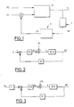
- la Fig.1 représente un schéma synoptique illustrant le fonctionnement d'un dispositif de contrôle selon l'invention; et
- les Fig.2 et 3 représentent des schémas de principe illustrant la régulation appliquée à un paramètre de contrôle du fonctionnement d'un moteur, dans un procédé selon l'invention.
- Fig.1 shows a block diagram illustrating the operation of a control device according to the invention; and
- Figs 2 and 3 show block diagrams illustrating the regulation applied to a parameter for controlling the operation of an engine, in a method according to the invention.
Sur la Fig.1, le moteur d'un véhicule automobile est schématisé par le bloc désigné par la référence générale 1 et reçoit en entrée des paramètres de contrôle de son fonctionnement, désignés par exemple par les références P1 et P2.In Fig.1, the engine of a motor vehicle is shown diagrammatically by the block designated by the
La sortie de ce moteur est illustrée par le régime N de celui-ci.The output of this engine is illustrated by the speed N thereof.
On conçoit que ce régime N est fonction des différents paramètres P1 et P2 de contrôle du fonctionnement de ce moteur.It is understood that this regime N is a function of the various parameters P1 and P2 for controlling the operation of this engine.
Ainsi qu'on l'a mentionné précédemment, le procédé et le dispositif selon l'invention sont adaptés pour amortir les oscillations longitudinales du véhicule engendrées par les oscillations du régime moteur.As mentioned previously, the method and the device according to the invention are suitable for damping the longitudinal oscillations of the vehicle generated by the oscillations of the engine speed.
Le procédé selon l'invention consiste à élaborer un signal de régime moteur filtré NF représentatif des oscillations de ce régime N et à asservir ce signal de régime moteur filtré à 0, par calcul d'une correction à apporter au couple moteur et détermination de la correction correspondante à appliquer à un paramètre de contrôle du fonctionnement du moteur, à l'aide d'un régulateur numérique.The method according to the invention consists in developing a filtered engine speed signal NF representative of the oscillations of this speed N and in controlling this filtered engine speed signal to 0, by calculating a correction to be made to the engine torque and determining the corresponding correction to be applied to an engine operation control parameter, using a digital regulator.
Le régime filtré NF représentatif des oscillations du régime moteur N est obtenu par passage de ce régime dans un filtre désigné par la référence 2 sur cette figure, tandis que le régulateur numérique est désigné par la référence 3, la correction de sortie de celui-ci étant désignée par la référence CP et étant appliquée par exemple au paramètre P1 de contrôle du fonctionnement du moteur.The filtered speed NF representative of the oscillations of the engine speed N is obtained by passing this speed through a filter designated by
Il va de soi que le filtre 2 peut être intégré dans le régulateur 3.It goes without saying that the
On notera également que ce paramètre de contrôle est par exemple l'avance à l'allumage. Cependant, la correction peut également être appliquée à d'autres paramètres de contrôle du fonctionnement du moteur comme cela sera décrit plus en détail par la suite.It will also be noted that this control parameter is for example the ignition advance. However, the correction can also be applied to other parameters for controlling the operation of the engine as will be described in more detail below.
Les paramètres du régulateur numérique ont été quant à eux préalablement calculés à partir d'un modèle estimateur du couple moteur dans lequel sont introduits les paramètres de contrôle du fonctionnement du moteur et d'un modèle estimateur de transmission filtré pour chaque rapport de boîte de vitesses.The parameters of the digital regulator have been calculated beforehand from a model estimating the engine torque into which are introduced the parameters for controlling the operation of the engine and a filtered transmission estimator model for each gearbox report. .
L'identification du modèle estimateur du couple moteur ne présente pas de difficultés particulières et est réalisée par exemple conformément aux enseignements de la demande de brevet Français n° 91 11 919 mentionnée précédemment.The identification of the engine torque estimator model does not present any particular difficulties and is carried out for example in accordance with the teachings of French patent application No. 91 11 919 mentioned previously.
L'identification du modèle estimateur de transmission filtré est réalisée quant à elle à partir du couple moteur moyen sur chaque période d'échantillonnage constante du régulateur et d'un régime moteur filtré obtenu à partir d'un régime moteur interpolé linéairement entre des valeurs de régime mesurées à deux références angulaires déterminées du moteur, encadrant l'instant d'échantillonnage.The identification of the filtered transmission estimator model is carried out on the basis of the average engine torque over each constant sampling period of the regulator and of a filtered engine speed obtained from an engine speed interpolated linearly between values of speed measured at two determined angular references of the engine, framing the sampling instant.
Ce modèle peut être obtenu de la façon suivante.This model can be obtained as follows.
La première phase d'identification de ce modèle est une phase d'analyse du fonctionnement du moteur du véhicule. Ce véhicule est équipé d'un calculateur de commande de l'allumage et de l'injection qui ne fait aucune correction sur les paramètres de contrôle du fonctionnement du moteur de celui-ci.The first phase of identification of this model is a phase of analysis of the functioning of the vehicle engine. This vehicle is equipped with an ignition and injection control computer which does not make any corrections to the parameters controlling its operation.
Ces paramètres sont alors directement issus d'une cartographie statique et on dit que le système fonctionne en boucle ouverte.These parameters then come directly from a static mapping and we say that the system works in open loop.
Il y a ensuite lieu de se placer à un régime moteur stabilisé, c'est à dire sans trop d'oscillations résiduelles et d'accélérer de manière à provoquer une oscillation non négligeable du véhicule.It is then necessary to move to a stabilized engine speed, that is to say without too much residual oscillation and to accelerate so as to cause a significant oscillation of the vehicle.
A chaque référence angulaire déterminée du moteur, par exemple située avant chaque point mort haut de celui-ci, on mesure la pression d'admission ou le débit d'air dans le moteur, le régime moteur, l'avance à l'allumage et le temps écoulé depuis le début de la mesure en vue d'une datation des résultats.At each determined angular reference of the engine, for example located before each top dead center thereof, the intake pressure or the air flow in the engine, the engine speed, the ignition advance and the time since the start of the measurement to date the results.
Ces différentes mesures permettent de reconstituer en temps différé le couple délivré par le moteur et le moment où il est délivré grâce à la datation.These various measurements make it possible to reconstitute in deferred time the torque delivered by the engine and the moment when it is delivered thanks to dating.
Le calcul du couple moteur par un triplet pression, régime, avance est décrit dans la demande de brevet mentionnée précédemment.The calculation of the engine torque by a pressure, speed, advance triplet is described in the patent application mentioned above.
Cependant, la période de travail, c'est à dire la période d'échantillonnage, étant constante, il n'existe aucune synchronisation entre les références angulaires déterminées et les instants d'échantillonnage.However, the working period, that is to say the sampling period, being constant, there is no synchronization between the determined angular references and the sampling instants.
Or, il est nécessaire pour identifier le modèle de connaître le couple moteur et le régime filtré à chaque instant d'échantillonnage.However, to identify the model, it is necessary to know the engine torque and the filtered speed at each sampling instant.
Ces signaux sont reconstitués de la façon suivante :
- a) couple : le couple utilisé est le couple moyen calculé sur chaque période d'échantillonnage;
- b) régime : le régime non filtré à l'instant n est le résultat d'une interpolation linéaire entre les valeurs de régime mesurées aux deux références angulaires déterminées du moteur encadrant l'instant d'échantillonnage, ce qui est suffisant car le régime varie lentement d'une référence angulaire à l'autre.
- a) torque: the torque used is the average torque calculated over each sampling period;
- b) speed: the speed not filtered at time n is the result of a linear interpolation between the speed values measured at the two angular references determined by the engine framing the sampling instant, which is sufficient because the speed varies slowly from one angular reference to another.
Le régime filtré est ensuite obtenu à partir de ce régime interpolé par passage dans un filtre passe-haut d'ordre au moins égal à deux pour éliminer à la fois une composante continue et une variation constante afin de ne pas corriger le système lors d'une accélération constante sans oscillation.The filtered regime is then obtained from this interpolated regime by passing through a high-pass filter of order at least equal to two to eliminate both a continuous component and a constant variation so as not to correct the system during constant acceleration without oscillation.
On conçoit alors qu'à partir de ce couple moteur et du régime filtré, il est possible d'identifier le modèle retraçant au mieux le signal de sortie pour une même entrée.It can therefore be seen that, from this engine torque and the filtered speed, it is possible to identify the model that best traces the output signal for the same input.
Des logiciels peuvent être utilisés pour identifier le modèle à partir de ces informations.Software can be used to identify the model from this information.
Des renseignements complémentaires concernant cette identification pourront être trouvés dans " IDENTIFICATION ET COMMANDE DES SYSTEMES " par IOAN DORE LANDAU, Traités des Nouvelles Technologies, série automatique, édition Hermès, 1988.Additional information concerning this identification can be found in "IDENTIFICATION AND ORDER OF SYSTEMS" by IOAN DORE LANDAU, Treaties of New Technologies, automatic series, Hermès edition, 1988.
La période d'échantillonnage est choisie pour avoir un nombre d'échantillons par période supérieur à quatre et pour être plus grande que la petite durée d'un cycle moteur.The sampling period is chosen to have a number of samples per period greater than four and to be greater than the short duration of an engine cycle.
Le régulateur peut être constitué par un régulateur à structure dite RST dont on trouvera une description détaillée dans le document mentionné ci-dessus.The regulator can be constituted by a regulator with a structure known as RST of which one will find a detailed description in the document mentioned above.
Ce régulateur est utilisé pour amortir les oscillations du régime moteur en asservissant le signal de régime moteur filtré à 0, comme cela est illustré sur la Fig.2.This regulator is used to dampen the engine speed oscillations by slaving the filtered engine speed signal to 0, as illustrated in Fig.2.
Sur cette figure, U0 représente l'apport de couple dû au conducteur du véhicule, c'est à dire la perturbation.In this figure, U 0 represents the contribution of torque due to the driver of the vehicle, that is to say the disturbance.
Le modèle estimateur de transmission filtré est quant à lui représenté par une fonction de transfert discrète B/A où B et A sont des polynômes déterminés de la façon indiquée précédemment.The filtered transmission estimator model is represented by a discrete transfer function B / A where B and A are polynomials determined as indicated above.
Les paramètres R et S du régulateur sont également des polynômes.The R and S parameters of the regulator are also polynomials.
On conçoit alors que la fonction de transfert en boucle fermée de ce régulateur, liant la perturbation Uo au régime filtré NF, est :![]()
![]()
Les amortissements et les fréquences propres du système sont déterminés par le dénominateur AS + BR.The damping and the natural frequencies of the system are determined by the denominator AS + BR.
On détermine ensuite un polynôme cible ou idéal appelé P et on résout l'équation polynômiale dite de BEZOUT :![]()
![]()
Le polynôme idéal P peut être obtenu par modification du polynôme A dans la mesure où il n'est pas nécessaire de modifier les fréquences d'oscillations ni les amortissements des fréquences élevées.The ideal polynomial P can be obtained by modifying the polynomial A insofar as it is not necessary to modify the oscillation frequencies or the damping of the high frequencies.
Le polynôme A peut alors être décomposé sous forme de polynômes de premier et de second ordres de façon à faire apparaître fréquences et amortissements et on augmente alors l'amortissement correspondant à la fréquence à amortir pour obtenir un polynôme modifié que l'on peut utiliser comme polynôme P.The polynomial A can then be decomposed in the form of first and second order polynomials so as to show frequencies and dampings and the damping corresponding to the frequency to be damped is then increased to obtain a modified polynomial which can be used as polynomial P.
Des méthodes classiques d'évaluation et d'amélioration de la robustesse du régulateur peuvent ensuite être appliquées pour optimiser sa capacité à conserver ses performances lorsque les caractéristiques du système sur lequel il s'applique, varient.Conventional methods for evaluating and improving the robustness of the regulator can then be applied to optimize its ability to maintain its performance when the characteristics of the system to which it is applied vary.
L'évaluation de la robustesse se fait de façon classique au travers:
- de différentes marges :
- * marge de gain
- * marge de phase
- * marge de retard
- * marge de module
Ces marges sont calculées à partir du diagramme de NYQUIST. - de deux fonctions de sensibilité :
- * sensibilité à une perturbation appliquée sur la sortie (NF) :
Fonction de transfert :
- * sensibilité à une perturbation appliquée sur la commande (Uo) :
Fonction de transfert :
- * sensibilité à une perturbation appliquée sur la sortie (NF) :
- of different margins:
- * profit margin
- * phase margin
- * margin of delay
- * module margin
These margins are calculated from the NYQUIST diagram. - two sensitivity functions:
- * sensitivity to a disturbance applied to the output (NF):
Transfer function : - * sensitivity to a disturbance applied to the control (U o ):
Transfer function :
- * sensitivity to a disturbance applied to the output (NF):
La sensibilité de chaque fonction de transfert est déterminée en traçant le diagramme de BODE correspondant.The sensitivity of each transfer function is determined by drawing the corresponding BODE diagram.
Lors de la détermination du régulateur, il faut arriver à faire un compromis entre tous ces critères afin de les respecter au mieux. Pour cela, il existe plusieurs moyens d'actions.When determining the regulator, it is necessary to reach a compromise between all these criteria in order to respect them as well as possible. For this, there are several means of action.
En effet, il est possible de modifier et d'ajouter des racines au polynôme P (pour mieux le spécifier) sans augmenter les degrés de R et de S jusqu'à un certain point. L'avantage de cette méthode est d'améliorer la robustesse du régulateur sans le compliquer.Indeed, it is possible to modify and add roots to the polynomial P (to better specify it) without increasing the degrees of R and S to a certain point. The advantage of this method is to improve the robustness of the regulator without complicating it.
Cependant, il est également possible d'ajouter un polynôme Hr ou Hs.However, it is also possible to add a polynomial Hr or Hs.
Ces polynômes sont définis da la manière suivante:![]()
![]()
![]()
![]()
Si par exemple on introduit un polynôme Hr, l'identité de BEZOUT devient :![]()
![]()
En posant B' = B.Hr, l'équation s'écrit :![]()
![]()
Il en est de même pour Hs.It is the same for H s .
Le fait d'ajouter ce polynôme permet d'imposer une racine dans R (ou dans S). Cependant, pour chaque racine ajoutée, l'ordre de R et de S augmente et ainsi le régulateur devient plus complexe.The fact of adding this polynomial makes it possible to impose a root in R (or in S). However, for each root added, the order of R and S increases and thus the regulator becomes more complex.
On conçoit que le régulateur représenté sur la Fig.2 permet d'amortir rapidement une oscillation du véhicule, mais ne permet pas de contrôler complètement l'accélération et en particulier l'amplitude de la première oscillation.It will be appreciated that the regulator shown in FIG. 2 makes it possible to quickly dampen an oscillation of the vehicle, but does not make it possible to completely control the acceleration and in particular the amplitude of the first oscillation.
Ceci se retrouve dans le fait que ce régulateur ne permet de choisir que le dénominateur de la fonction de transfert en boucle fermée, le numérateur BS étant entièrement subi.This is reflected in the fact that this regulator only allows to choose the denominator of the closed loop transfer function, the numerator BS being entirely subjected.
Pour résoudre ce problème, il est possible d'introduire dans ce régulateur, un signal de commande à action directe élaboré à partir du couple moteur Uo, pour contrôler l'allure de l'accélération du véhicule.To solve this problem, it is possible to introduce into this regulator, a direct action control signal developed from the engine torque U o , to control the speed of the vehicle's acceleration.
Ceci se traduit alors par l'introduction d'un polynôme T dans le régulateur comme cela est illustré sur la Fig.3.This then results in the introduction of a polynomial T in the regulator as illustrated in Fig.3.
La fonction de transfert en boucle fermée du régulateur est alors :![]()
![]()
L'introduction du polynôme T permet donc de contrôler partiellement le numérateur de la fonction de transfert et nécessite l'estimation du couple Uo qui serait délivré par le moteur si l'on ne faisait aucune correction.The introduction of the polynomial T therefore makes it possible to partially control the numerator of the transfer function and requires the estimation of the torque U o which would be delivered by the motor if no correction was made.
La formule récursive globale du calcul de la correction est alors :![]()
![]()
La correction à apporter au couple moteur à l'instant n est donc donnée par la relation :![]()
![]()
Le choix du polynôme T repose sur plusieurs critères.The choice of polynomial T is based on several criteria.
En effet, la correction apportée par ce polynôme doit être nulle si le couple Uo est constant afin d'éviter une correction permanente qui dégraderait le rendement du moteur.Indeed, the correction made by this polynomial must be zero if the torque U o is constant in order to avoid a permanent correction which would degrade the efficiency of the motor.
Cette condition impose que T a pour racine au moins la valeur 1, gain statique nul.This condition imposes that T has for root at least the
Par ailleurs, les racines de S + T doivent être disposées correctement à l'intérieur du cercle unité.In addition, the roots of S + T must be arranged correctly inside the unit circle.
Une solution possible pour calculer le polynôme T est de minimiser un critère quadratique regroupant les notions contradictoires d'amplitude d'oscillations d'une part et d'énergie de commande d'autre part.One possible solution for calculating the polynomial T is to minimize a quadratic criterion grouping together the contradictory notions of amplitude of oscillations on the one hand and control energy on the other hand.
Une autre solution possible réside dans une calibration manuelle sur le véhicule.Another possible solution is manual calibration on the vehicle.
Ce régulateur permet alors de déterminer une correction à apporter à l'un des paramètres de contrôle de fonctionnement du moteur pour obtenir une correction de couple et donc un amortissement des oscillations du véhicule et un contrôle de l'allure de l'accélération de celui-ci.This regulator then makes it possible to determine a correction to be made to one of the parameters for controlling the operation of the engine in order to obtain a torque correction and therefore a damping of the oscillations of the vehicle and a control of the pace of the acceleration of the latter. this.
Cette correction est appliquée par exemple grâce à l'avance à l'allumage, mais il va de soi bien entendu qu'un actionneur d'air tel qu'une vanne ou un papillon peut également être utilisé.This correction is applied for example thanks to the ignition advance, but it goes without saying of course that an air actuator such as a valve or a butterfly valve can also be used.
Dans le cas où la demande de correction de couple est appliquée par l'avance à l'allumage, comme dans la demande de brevet mentionnée précédemment, la demande de correction de couple par le régulateur, intervenant toutes les périodes d'échantillonnage et l'application de l'avance, intervenant toutes les références angulaires déterminées, ne sont pas synchrones.In the case where the request for torque correction is applied by the ignition advance, as in the patent application mentioned above, the request for torque correction by the regulator, intervening all the sampling periods and the application of the feed, intervening all the determined angular references, are not synchronous.
Il y a alors lieu de convertir les corrections de couple en corrections d'avance toutes les périodes d'échantillonnage, le calcul de l'avance réelle dépendant des paramètres de fonctionnement du moteur au moment de l'allumage, étant fait toutes les références angulaires déterminées.It is then necessary to convert the torque corrections into advance corrections all the sampling periods, the calculation of the actual advance depending on the operating parameters of the engine at the time of ignition, being made all the angular references. determined.
Par ailleurs, il est également nécessaire de connaître la correction réellement appliquée lors des périodes précédentes, qui peut différer de ce que l'on a demandé à cause des saturations.In addition, it is also necessary to know the correction actually applied during the previous periods, which can differ from what was asked because of saturation.
Pour cela, trois solutions peuvent être retenues et on considère alors que la correction appliquée pendant une période d'échantillonnage est soit la correction appliquée à la dernière référence angulaire déterminée, avant la période d'échantillonnage suivante, soit la moyenne des corrections appliquées à chaque référence angulaire déterminée pendant la période d'échantillonnage, soit la moyenne des corrections appliquées à chaque référence angulaire déterminée pendant la période d'échantillonnage, pondérée par le temps d'application de chaque correction.For this, three solutions can be retained and it is then considered that the correction applied during a sampling period is either the correction applied to the last angular reference determined, before the next sampling period, or the average of the corrections applied to each angular reference determined during the sampling period, ie the average of the corrections applied to each angular reference determined during the sampling period, weighted by the time of application of each correction.
On conçoit alors que le procédé et le dispositif selon l'invention utilise une correction basée sur un modèle identifié reliant le couple moteur au régime filtré et calculée à période fixe, appliquée à des références angulaires déterminées.It can therefore be seen that the method and the device according to the invention uses a correction based on an identified model relating the engine torque to the filtered speed. and calculated at a fixed period, applied to specific angular references.
De plus, le régulateur ne présente pas de seuil de déclenchement et il est possible de piloter l'allure de l'accélération du véhicule et de déterminer un bon compromis de confort d'utilisation du véhicule.In addition, the regulator does not have a triggering threshold and it is possible to control the rate of acceleration of the vehicle and to determine a good compromise in vehicle comfort of use.
Les contraintes de robustesse sont prises en compte lors du calcul du régulateur.The robustness constraints are taken into account when calculating the regulator.
Enfin, la charge de calcul en temps réel du régulateur est faible.Finally, the real-time computational load of the regulator is low.
Claims (6)
- A method for controlling the operation of an internal combustion engine of an automotive vehicle, by controlling at least one parameter (P1) for controlling the operation of this engine (1), characterised in that it consists in producing a filtered engine speed (NF) signal which is representative of the oscillations of the engine speed (N), and in locking in this filtered engine speed (NF) signal at 0, in order to deaden the oscillations of the engine speed, by calculating an adjustment to be made to the engine torque and by determining the corresponding adjustment (CP) to be applied to the said parameter for controlling the operation of the engine with the aid of a digital regulator (3) with its parameters calculated in advance using an estimator model of the engine torque into which the parameters for controlling the operation of the engine and for a filtered transmission estimator model are entered, for each gearbox ratio.
- A method according to Claim 1, characterised in that the digital regulator (3) is a RST-structure regulator which receives a direct action control signal produced using the engine torque (Uo) to control the speed of acceleration of the vehicle.
- A method according to either Claim 1 or 2, characterised in that the regulator has a period of constant sampling.
- A method according to Claim 3, characterised in that the estimator model (B/A) for filtered transmission is identified using the average engine speed at each sampling period of the regulator and a filtered speed obtained using a linearly interpolated speed between speed values measured at two determined angular references of the engine, which angular references surround the sampling moment.
- A method according to Claim 4, characterised in that the filtered speed is obtained by passing of the interpolated speed into at least a second order high-pass filter.
- A device for controlling the operation of an internal combustion engine of an automotive vehicle for implementing the method according to any one of the preceding claims with means for controlling at least one parameter (P1) for controlling the operation of this engine (1), characterised in that it comprises means (2) for producing a filtered engine speed signal representative of engine speed (N) oscillations, and a regulator (3) for locking in this filtered engine signal at 0, wherein this regulator comprises means for calculating an adjustment to be made to the engine torque and for determining the corresponding adjustment (CP) to be applied to the said parameter for control of operation of the engine, wherein the parameters of the regulator are calculated in advance using the estimator model of the engine torque into which the parameters for controlling the operation of the engine and for a transmission filtered estimator model are entered, for each gearbox ratio.
Applications Claiming Priority (2)
| Application Number | Priority Date | Filing Date | Title |
|---|---|---|---|
| FR9303605A FR2703404B1 (en) | 1993-03-29 | 1993-03-29 | METHOD AND DEVICE FOR MONITORING THE OPERATION OF AN INTERNAL COMBUSTION ENGINE OF A MOTOR VEHICLE. |
| FR9303605 | 1993-03-29 |
Publications (2)
| Publication Number | Publication Date |
|---|---|
| EP0618355A1 EP0618355A1 (en) | 1994-10-05 |
| EP0618355B1 true EP0618355B1 (en) | 1996-12-27 |
Family
ID=9445460
Family Applications (1)
| Application Number | Title | Priority Date | Filing Date |
|---|---|---|---|
| EP19940400602 Expired - Lifetime EP0618355B1 (en) | 1993-03-29 | 1994-03-18 | Method and device for controlling of the operation of a combustion engine for an automotive vehicle |
Country Status (3)
| Country | Link |
|---|---|
| EP (1) | EP0618355B1 (en) |
| DE (1) | DE69401229T2 (en) |
| FR (1) | FR2703404B1 (en) |
Families Citing this family (2)
| Publication number | Priority date | Publication date | Assignee | Title |
|---|---|---|---|---|
| FR2945079A1 (en) * | 2009-04-29 | 2010-11-05 | Peugeot Citroen Automobiles Sa | Method for controlling operation of engine e.g. direct injection compression ignition engine, of motor vehicle, involves determining stability of torque of modeled engine, and modifying parameters of filter when torque is unstable |
| CN111946470B (en) * | 2020-07-31 | 2021-11-23 | 东风汽车集团有限公司 | Method for determining minimum ignition speed of direct injection gasoline engine and storage medium |
Family Cites Families (5)
| Publication number | Priority date | Publication date | Assignee | Title |
|---|---|---|---|---|
| DE2906782A1 (en) * | 1979-02-22 | 1980-09-04 | Bosch Gmbh Robert | DEVICE FOR DAMPING VIBRATION VIBRATIONS IN AN INTERNAL COMBUSTION ENGINE |
| US4418669A (en) * | 1982-07-19 | 1983-12-06 | The Bendix Corporation | Fuel distribution control system for an internal combustion engine |
| JPS5960340A (en) * | 1982-09-30 | 1984-04-06 | Japanese National Railways<Jnr> | Ride comfort measuring device for track |
| JP2674077B2 (en) * | 1988-04-12 | 1997-11-05 | トヨタ自動車株式会社 | Non-linear feedback control method for internal combustion engine |
| FR2681908A1 (en) * | 1991-09-27 | 1993-04-02 | Peugeot | METHOD FOR CORRECTING THE CONTROL PARAMETERS OF AN INTERNAL COMBUSTION ENGINE AND DEVICE FOR IMPLEMENTING THE METHOD. |
-
1993
- 1993-03-29 FR FR9303605A patent/FR2703404B1/en not_active Expired - Fee Related
-
1994
- 1994-03-18 EP EP19940400602 patent/EP0618355B1/en not_active Expired - Lifetime
- 1994-03-18 DE DE1994601229 patent/DE69401229T2/en not_active Expired - Fee Related
Also Published As
| Publication number | Publication date |
|---|---|
| DE69401229T2 (en) | 1997-04-24 |
| EP0618355A1 (en) | 1994-10-05 |
| FR2703404A1 (en) | 1994-10-07 |
| FR2703404B1 (en) | 1995-06-30 |
| DE69401229D1 (en) | 1997-02-06 |
Similar Documents
| Publication | Publication Date | Title |
|---|---|---|
| EP1994390B1 (en) | Method for real-time estimation of engine combustion parameters from vibratory signals | |
| EP2373964B1 (en) | Method and system for correcting a temperature measurement signal | |
| EP2917537B1 (en) | Method for monitoring a thrust fault of an aircraft turbofan | |
| EP1898075A1 (en) | Method for real-time estimation of combustion state indicators in an internal combustion engine | |
| FR2868157A1 (en) | METHOD AND DEVICE FOR DETERMINING THE ANGULAR POSITION OF ROTATION OF A TREE | |
| WO2007028584A1 (en) | Method of determining the reversal of the direction of rotation of an engine | |
| FR2524554A1 (en) | APPARATUS FOR ADJUSTING THE OPERATION OF AN INTERNAL COMBUSTION ENGINE | |
| FR2704023A1 (en) | Method and apparatus for controlling a fuel injection system | |
| FR2472091A1 (en) | IGNITION DEVICE AVOIDING KNOCKING DURING THE OPERATION OF AN INTERNAL COMBUSTION ENGINE | |
| EP0534813B1 (en) | Method for correcting the control parameters of an internal combustion engine and device for implementing this method | |
| EP1815223B1 (en) | Device for controlling an internal combustion engine | |
| EP1002190A1 (en) | Method for correcting an internal combustion engine torque jerks | |
| EP0655554B1 (en) | Method of correction of torque jerks of an internal combustion engine | |
| FR2722568A1 (en) | METHOD FOR FORMING A SIMULATED SIGNAL WITH REGARD TO A TEMPERATURE IN THE EXHAUST SYSTEM OF AN INTERNAL COMBUSTION ENGINE | |
| FR2467396A1 (en) | CLICK SENSOR FOR AN INTERNAL COMBUSTION ENGINE | |
| EP0618355B1 (en) | Method and device for controlling of the operation of a combustion engine for an automotive vehicle | |
| WO2018172665A1 (en) | Method for managing pinking in a controlled-ignition internal combustion engine | |
| FR2872282A1 (en) | Pressure measurement signal processing method for internal combustion engine, involves applying inverse wavelet transform to one set of transformed signals obtained by applying non-linear thresholding functions to another set of signals | |
| EP2480776B1 (en) | Prediction of engine rotation speed during the end of rotation and application of the prediction for an estimation of crankcase stop position | |
| FR2937383A1 (en) | Pinking controlling method for internal combustion engine of motor vehicle, involves, storing modification value of spark advance, and modifying spark advance at previous time by applying stored modification value at anterior time | |
| FR2718191A1 (en) | Suppression oscillation along automobile longitudinal axis | |
| FR2818737A1 (en) | METHOD FOR DETECTING A SINGULARITY IN PARTICULAR OF A REFERENCE MARK OF A PHONE DISC ASSOCIATED WITH THE SHAFT OF AN INTERNAL COMBUSTION ENGINE | |
| EP1888901B1 (en) | Method for noise reduction of an injection diesel engine | |
| EP0702138B1 (en) | Method and device for the suppression of longitudinal oscillations of a motorised automotive vehicle | |
| WO2008084150A1 (en) | Method for controlling the torque of an alternator in an automotive vehicle and system for implementing said method |
Legal Events
| Date | Code | Title | Description |
|---|---|---|---|
| PUAI | Public reference made under article 153(3) epc to a published international application that has entered the european phase |
Free format text: ORIGINAL CODE: 0009012 |
|
| AK | Designated contracting states |
Kind code of ref document: A1 Designated state(s): DE GB IT |
|
| 17P | Request for examination filed |
Effective date: 19950313 |
|
| GRAG | Despatch of communication of intention to grant |
Free format text: ORIGINAL CODE: EPIDOS AGRA |
|
| GRAH | Despatch of communication of intention to grant a patent |
Free format text: ORIGINAL CODE: EPIDOS IGRA |
|
| 17Q | First examination report despatched |
Effective date: 19960521 |
|
| GRAH | Despatch of communication of intention to grant a patent |
Free format text: ORIGINAL CODE: EPIDOS IGRA |
|
| GRAA | (expected) grant |
Free format text: ORIGINAL CODE: 0009210 |
|
| RAP1 | Party data changed (applicant data changed or rights of an application transferred) |
Owner name: AUTOMOBILES CITROEN Owner name: AUTOMOBILES PEUGEOT |
|
| AK | Designated contracting states |
Kind code of ref document: B1 Designated state(s): DE GB IT |
|
| ITF | It: translation for a ep patent filed |
Owner name: GUZZI E RAVIZZA S.R.L. |
|
| REF | Corresponds to: |
Ref document number: 69401229 Country of ref document: DE Date of ref document: 19970206 |
|
| GBT | Gb: translation of ep patent filed (gb section 77(6)(a)/1977) |
Effective date: 19970125 |
|
| PLBE | No opposition filed within time limit |
Free format text: ORIGINAL CODE: 0009261 |
|
| STAA | Information on the status of an ep patent application or granted ep patent |
Free format text: STATUS: NO OPPOSITION FILED WITHIN TIME LIMIT |
|
| 26N | No opposition filed | ||
| REG | Reference to a national code |
Ref country code: GB Ref legal event code: IF02 |
|
| REG | Reference to a national code |
Ref country code: GB Ref legal event code: 746 Effective date: 20070115 |
|
| PGFP | Annual fee paid to national office [announced via postgrant information from national office to epo] |
Ref country code: DE Payment date: 20070307 Year of fee payment: 14 |
|
| PGFP | Annual fee paid to national office [announced via postgrant information from national office to epo] |
Ref country code: IT Payment date: 20080307 Year of fee payment: 15 Ref country code: GB Payment date: 20080225 Year of fee payment: 15 |
|
| PG25 | Lapsed in a contracting state [announced via postgrant information from national office to epo] |
Ref country code: DE Free format text: LAPSE BECAUSE OF NON-PAYMENT OF DUE FEES Effective date: 20081001 |
|
| GBPC | Gb: european patent ceased through non-payment of renewal fee |
Effective date: 20090318 |
|
| PG25 | Lapsed in a contracting state [announced via postgrant information from national office to epo] |
Ref country code: GB Free format text: LAPSE BECAUSE OF NON-PAYMENT OF DUE FEES Effective date: 20090318 |
|
| PG25 | Lapsed in a contracting state [announced via postgrant information from national office to epo] |
Ref country code: IT Free format text: LAPSE BECAUSE OF NON-PAYMENT OF DUE FEES Effective date: 20090318 |