EP0618067B1 - Stainless steel and carbon steel composite, and method of producing the same - Google Patents
Stainless steel and carbon steel composite, and method of producing the same Download PDFInfo
- Publication number
- EP0618067B1 EP0618067B1 EP94301532A EP94301532A EP0618067B1 EP 0618067 B1 EP0618067 B1 EP 0618067B1 EP 94301532 A EP94301532 A EP 94301532A EP 94301532 A EP94301532 A EP 94301532A EP 0618067 B1 EP0618067 B1 EP 0618067B1
- Authority
- EP
- European Patent Office
- Prior art keywords
- carbon steel
- composite material
- stabilized
- steel
- carbon
- Prior art date
- Legal status (The legal status is an assumption and is not a legal conclusion. Google has not performed a legal analysis and makes no representation as to the accuracy of the status listed.)
- Expired - Lifetime
Links
- 239000002131 composite material Substances 0.000 title claims abstract description 69
- 229910000975 Carbon steel Inorganic materials 0.000 title claims abstract description 56
- 239000010962 carbon steel Substances 0.000 title claims abstract description 52
- 229910001220 stainless steel Inorganic materials 0.000 title claims abstract description 37
- 239000010935 stainless steel Substances 0.000 title claims abstract description 36
- 238000000034 method Methods 0.000 title claims description 20
- OKTJSMMVPCPJKN-UHFFFAOYSA-N Carbon Chemical compound [C] OKTJSMMVPCPJKN-UHFFFAOYSA-N 0.000 claims abstract description 43
- 229910052799 carbon Inorganic materials 0.000 claims abstract description 41
- 239000010955 niobium Substances 0.000 claims abstract description 23
- GUCVJGMIXFAOAE-UHFFFAOYSA-N niobium atom Chemical compound [Nb] GUCVJGMIXFAOAE-UHFFFAOYSA-N 0.000 claims abstract description 22
- 238000013508 migration Methods 0.000 claims abstract description 8
- 230000005012 migration Effects 0.000 claims abstract description 8
- 229910052758 niobium Inorganic materials 0.000 claims description 22
- IJGRMHOSHXDMSA-UHFFFAOYSA-N Atomic nitrogen Chemical compound N#N IJGRMHOSHXDMSA-UHFFFAOYSA-N 0.000 claims description 20
- 229910052719 titanium Inorganic materials 0.000 claims description 19
- 239000010936 titanium Substances 0.000 claims description 19
- RTAQQCXQSZGOHL-UHFFFAOYSA-N Titanium Chemical compound [Ti] RTAQQCXQSZGOHL-UHFFFAOYSA-N 0.000 claims description 18
- 238000000137 annealing Methods 0.000 claims description 13
- 229910052757 nitrogen Inorganic materials 0.000 claims description 10
- 238000004519 manufacturing process Methods 0.000 claims description 6
- 239000012535 impurity Substances 0.000 claims description 5
- QCWXUUIWCKQGHC-UHFFFAOYSA-N Zirconium Chemical compound [Zr] QCWXUUIWCKQGHC-UHFFFAOYSA-N 0.000 claims description 2
- 229910052715 tantalum Inorganic materials 0.000 claims description 2
- GUVRBAGPIYLISA-UHFFFAOYSA-N tantalum atom Chemical compound [Ta] GUVRBAGPIYLISA-UHFFFAOYSA-N 0.000 claims description 2
- 229910052726 zirconium Inorganic materials 0.000 claims description 2
- XEEYBQQBJWHFJM-UHFFFAOYSA-N Iron Chemical compound [Fe] XEEYBQQBJWHFJM-UHFFFAOYSA-N 0.000 claims 8
- 229910052742 iron Inorganic materials 0.000 claims 4
- 239000011162 core material Substances 0.000 abstract description 52
- 229910001209 Low-carbon steel Inorganic materials 0.000 abstract description 10
- 239000010410 layer Substances 0.000 description 20
- 229910000859 α-Fe Inorganic materials 0.000 description 19
- 239000002244 precipitate Substances 0.000 description 16
- 238000001816 cooling Methods 0.000 description 13
- 229910045601 alloy Inorganic materials 0.000 description 12
- 239000000956 alloy Substances 0.000 description 12
- 229910000831 Steel Inorganic materials 0.000 description 11
- 239000010959 steel Substances 0.000 description 11
- 230000007547 defect Effects 0.000 description 10
- 238000000429 assembly Methods 0.000 description 9
- 230000000712 assembly Effects 0.000 description 9
- 238000012545 processing Methods 0.000 description 9
- 230000015572 biosynthetic process Effects 0.000 description 8
- 239000002516 radical scavenger Substances 0.000 description 7
- 239000000243 solution Substances 0.000 description 7
- 239000002344 surface layer Substances 0.000 description 7
- 229910001566 austenite Inorganic materials 0.000 description 6
- 239000000155 melt Substances 0.000 description 6
- 150000001247 metal acetylides Chemical class 0.000 description 6
- 238000005096 rolling process Methods 0.000 description 5
- 238000013459 approach Methods 0.000 description 4
- -1 carbon forms carbides Chemical class 0.000 description 4
- 239000012792 core layer Substances 0.000 description 4
- 238000009826 distribution Methods 0.000 description 4
- 239000000203 mixture Substances 0.000 description 4
- 239000006104 solid solution Substances 0.000 description 4
- 239000010963 304 stainless steel Substances 0.000 description 3
- 229910000851 Alloy steel Inorganic materials 0.000 description 3
- 229910000589 SAE 304 stainless steel Inorganic materials 0.000 description 3
- 229910052804 chromium Inorganic materials 0.000 description 3
- 239000011651 chromium Substances 0.000 description 3
- 239000012467 final product Substances 0.000 description 3
- 238000005098 hot rolling Methods 0.000 description 3
- 239000000463 material Substances 0.000 description 3
- 150000004767 nitrides Chemical class 0.000 description 3
- 238000001953 recrystallisation Methods 0.000 description 3
- 230000006641 stabilisation Effects 0.000 description 3
- 238000011105 stabilization Methods 0.000 description 3
- 238000012360 testing method Methods 0.000 description 3
- XLYOFNOQVPJJNP-UHFFFAOYSA-N water Substances O XLYOFNOQVPJJNP-UHFFFAOYSA-N 0.000 description 3
- VYZAMTAEIAYCRO-UHFFFAOYSA-N Chromium Chemical compound [Cr] VYZAMTAEIAYCRO-UHFFFAOYSA-N 0.000 description 2
- 230000008901 benefit Effects 0.000 description 2
- 150000001721 carbon Chemical class 0.000 description 2
- 238000002474 experimental method Methods 0.000 description 2
- 238000000227 grinding Methods 0.000 description 2
- 229910052751 metal Inorganic materials 0.000 description 2
- 239000002184 metal Substances 0.000 description 2
- 238000012805 post-processing Methods 0.000 description 2
- 230000008569 process Effects 0.000 description 2
- 238000010791 quenching Methods 0.000 description 2
- 230000000171 quenching effect Effects 0.000 description 2
- ZOXJGFHDIHLPTG-UHFFFAOYSA-N Boron Chemical compound [B] ZOXJGFHDIHLPTG-UHFFFAOYSA-N 0.000 description 1
- ZOKXTWBITQBERF-UHFFFAOYSA-N Molybdenum Chemical compound [Mo] ZOKXTWBITQBERF-UHFFFAOYSA-N 0.000 description 1
- NINIDFKCEFEMDL-UHFFFAOYSA-N Sulfur Chemical compound [S] NINIDFKCEFEMDL-UHFFFAOYSA-N 0.000 description 1
- 229910052770 Uranium Inorganic materials 0.000 description 1
- YTPZWYPLOCEZIX-UHFFFAOYSA-N [Nb]#[Nb] Chemical compound [Nb]#[Nb] YTPZWYPLOCEZIX-UHFFFAOYSA-N 0.000 description 1
- 229910052782 aluminium Inorganic materials 0.000 description 1
- XAGFODPZIPBFFR-UHFFFAOYSA-N aluminium Chemical compound [Al] XAGFODPZIPBFFR-UHFFFAOYSA-N 0.000 description 1
- 229910052796 boron Inorganic materials 0.000 description 1
- 229910021386 carbon form Inorganic materials 0.000 description 1
- 230000008859 change Effects 0.000 description 1
- 229910017052 cobalt Inorganic materials 0.000 description 1
- 239000010941 cobalt Substances 0.000 description 1
- GUTLYIVDDKVIGB-UHFFFAOYSA-N cobalt atom Chemical compound [Co] GUTLYIVDDKVIGB-UHFFFAOYSA-N 0.000 description 1
- 150000001875 compounds Chemical class 0.000 description 1
- 230000007797 corrosion Effects 0.000 description 1
- 238000005260 corrosion Methods 0.000 description 1
- 230000003247 decreasing effect Effects 0.000 description 1
- 230000001419 dependent effect Effects 0.000 description 1
- 238000011161 development Methods 0.000 description 1
- 238000004090 dissolution Methods 0.000 description 1
- 230000002349 favourable effect Effects 0.000 description 1
- 238000009472 formulation Methods 0.000 description 1
- 238000010438 heat treatment Methods 0.000 description 1
- BHEPBYXIRTUNPN-UHFFFAOYSA-N hydridophosphorus(.) (triplet) Chemical compound [PH] BHEPBYXIRTUNPN-UHFFFAOYSA-N 0.000 description 1
- WPBNNNQJVZRUHP-UHFFFAOYSA-L manganese(2+);methyl n-[[2-(methoxycarbonylcarbamothioylamino)phenyl]carbamothioyl]carbamate;n-[2-(sulfidocarbothioylamino)ethyl]carbamodithioate Chemical compound [Mn+2].[S-]C(=S)NCCNC([S-])=S.COC(=O)NC(=S)NC1=CC=CC=C1NC(=S)NC(=O)OC WPBNNNQJVZRUHP-UHFFFAOYSA-L 0.000 description 1
- 229910052750 molybdenum Inorganic materials 0.000 description 1
- 239000011733 molybdenum Substances 0.000 description 1
- 125000004433 nitrogen atom Chemical group N* 0.000 description 1
- 230000035515 penetration Effects 0.000 description 1
- 238000007781 pre-processing Methods 0.000 description 1
- 238000001556 precipitation Methods 0.000 description 1
- 238000001226 reprecipitation Methods 0.000 description 1
- 238000000926 separation method Methods 0.000 description 1
- 229910052717 sulfur Inorganic materials 0.000 description 1
- 239000011593 sulfur Substances 0.000 description 1
- 238000012956 testing procedure Methods 0.000 description 1
- 230000009466 transformation Effects 0.000 description 1
- MTPVUVINMAGMJL-UHFFFAOYSA-N trimethyl(1,1,2,2,2-pentafluoroethyl)silane Chemical compound C[Si](C)(C)C(F)(F)C(F)(F)F MTPVUVINMAGMJL-UHFFFAOYSA-N 0.000 description 1
- WFKWXMTUELFFGS-UHFFFAOYSA-N tungsten Chemical compound [W] WFKWXMTUELFFGS-UHFFFAOYSA-N 0.000 description 1
- 229910052721 tungsten Inorganic materials 0.000 description 1
- 239000010937 tungsten Substances 0.000 description 1
- DNYWZCXLKNTFFI-UHFFFAOYSA-N uranium Chemical compound [U][U][U][U][U][U][U][U][U][U][U][U][U][U][U][U][U][U][U][U][U][U][U][U][U][U][U][U][U][U][U][U][U][U][U][U][U][U][U][U][U][U][U][U][U][U][U][U][U][U][U][U][U][U][U][U][U][U][U][U][U][U][U][U][U][U][U][U][U][U][U][U][U][U][U][U][U][U][U][U][U][U][U][U][U][U][U][U][U][U][U][U][U][U][U][U][U][U][U][U][U][U][U][U][U][U][U][U][U][U][U][U][U][U] DNYWZCXLKNTFFI-UHFFFAOYSA-N 0.000 description 1
- 229910052720 vanadium Inorganic materials 0.000 description 1
- GPPXJZIENCGNKB-UHFFFAOYSA-N vanadium Chemical compound [V]#[V] GPPXJZIENCGNKB-UHFFFAOYSA-N 0.000 description 1
Images


Classifications
-
- B—PERFORMING OPERATIONS; TRANSPORTING
- B32—LAYERED PRODUCTS
- B32B—LAYERED PRODUCTS, i.e. PRODUCTS BUILT-UP OF STRATA OF FLAT OR NON-FLAT, e.g. CELLULAR OR HONEYCOMB, FORM
- B32B15/00—Layered products comprising a layer of metal
- B32B15/01—Layered products comprising a layer of metal all layers being exclusively metallic
- B32B15/011—Layered products comprising a layer of metal all layers being exclusively metallic all layers being formed of iron alloys or steels
-
- B—PERFORMING OPERATIONS; TRANSPORTING
- B23—MACHINE TOOLS; METAL-WORKING NOT OTHERWISE PROVIDED FOR
- B23K—SOLDERING OR UNSOLDERING; WELDING; CLADDING OR PLATING BY SOLDERING OR WELDING; CUTTING BY APPLYING HEAT LOCALLY, e.g. FLAME CUTTING; WORKING BY LASER BEAM
- B23K20/00—Non-electric welding by applying impact or other pressure, with or without the application of heat, e.g. cladding or plating
- B23K20/22—Non-electric welding by applying impact or other pressure, with or without the application of heat, e.g. cladding or plating taking account of the properties of the materials to be welded
- B23K20/227—Non-electric welding by applying impact or other pressure, with or without the application of heat, e.g. cladding or plating taking account of the properties of the materials to be welded with ferrous layer
-
- B—PERFORMING OPERATIONS; TRANSPORTING
- B32—LAYERED PRODUCTS
- B32B—LAYERED PRODUCTS, i.e. PRODUCTS BUILT-UP OF STRATA OF FLAT OR NON-FLAT, e.g. CELLULAR OR HONEYCOMB, FORM
- B32B15/00—Layered products comprising a layer of metal
- B32B15/01—Layered products comprising a layer of metal all layers being exclusively metallic
-
- Y—GENERAL TAGGING OF NEW TECHNOLOGICAL DEVELOPMENTS; GENERAL TAGGING OF CROSS-SECTIONAL TECHNOLOGIES SPANNING OVER SEVERAL SECTIONS OF THE IPC; TECHNICAL SUBJECTS COVERED BY FORMER USPC CROSS-REFERENCE ART COLLECTIONS [XRACs] AND DIGESTS
- Y10—TECHNICAL SUBJECTS COVERED BY FORMER USPC
- Y10T—TECHNICAL SUBJECTS COVERED BY FORMER US CLASSIFICATION
- Y10T428/00—Stock material or miscellaneous articles
- Y10T428/12—All metal or with adjacent metals
- Y10T428/12493—Composite; i.e., plural, adjacent, spatially distinct metal components [e.g., layers, joint, etc.]
- Y10T428/12771—Transition metal-base component
- Y10T428/12861—Group VIII or IB metal-base component
- Y10T428/12951—Fe-base component
- Y10T428/12972—Containing 0.01-1.7% carbon [i.e., steel]
- Y10T428/12979—Containing more than 10% nonferrous elements [e.g., high alloy, stainless]
Definitions
- the present invention relates to both a composite material and a method for producing the composite material. More particularly, the invention relates to both a pressure-bonded stainless steel and carbon steel composite material, and a method for producing the composite material.
- Pressure-bonded composites of individual layers of steel are used in a variety of applications.
- a composite comprising a core layer of plain carbon steel containing a carbide former and outer layers of stainless steel is used in producing certain metal items such as, for example, cookware.
- Related U.S. Patents include Nos. 3,795,971, 3,862,484, 3,944,396 and 3,956,809.
- the stainless steel surface layers of the composite are corrosion-resistant and provide an attractive appearance, while the plain carbon steel core layer has relatively greater heat conducting properties than the stainless steel layers.
- a specific example of this type of composite material is A.I.S.I.
- Type 304DA which has a conventional low carbon steel core material and surface layers of A.I.S.I. Type 304 stainless steel ("T-304").
- T-304DA which has a conventional low carbon steel core material and surface layers of A.I.S.I. Type 304 stainless steel ("T-304").
- T-304DA the standard practice is to cool the hot-rolled band to below 482°C (900°F) on the hot run out table before coiling. Failure to so cool the hot-rolled band to below (900°F) 482° C causes carbon from the low carbon steel core material to migrate into the interface region between the stainless steel surface layers and the low carbon steel core. This carbon migration occurs against the carbon concentration gradient and is dependent primarily on the attainment of an overall lower free energy. Such a migration against the concentration gradient frequently occurs from plain carbon steel to stainless steel because the stainless steel contains chromium which attracts the carbon.
- the carbon forms carbides, and thereby results in carbide enriched regions near the interface region. These carbide enriched regions cause so-called “Hook Cracks” upon drawing, an undesirable defect in the final product.
- carbon migration leads to the formation of a coarse ferrite grain layer in the low carbon core material which causes the defect known as "Orange Peel Surface” in the final product.
- failure to cool below 482°C (900°F) may result in metal separation, whereby one or more stainless steel layers delaminate from the low carbon steel core layer.
- Stainless steel/carbon steel composite materials may require annealing at temperatures greater than (1700°F) 927°C in order to release stresses built up during the bonding process and any subsequent cold forming, and to dissolve chromium carbides formed in the stainless steel layers.
- Typical carbon steels, such as type 1006, used as composite core material transform to a predominantly austenitic structure at temperatures below 927°C (1700°F), temperatures below the recrystallization temperature of typical stainless steels. Therefore, annealing at temperatures significantly greater than 927°C (1700°F) may cause significant coarsening of the austenite grains in the core layer, which transform into equally coarse ferrite grains upon cooling.
- the invention provides a pressure-bonded composite material in accordance with claim 1 of the appended claims.
- the invention further provides a method for producing a pressure-bonded composite material in accordance with claim 5 of the appended claims.
- the instant invention provides a pressure-bonded composite material which includes at least one layer of stainless steel bonded to at least one layer of a stabilized carbon steel along a stainless steel/carbon steel interface.
- the stabilized carbon steel of the composite includes carbon, niobium, and at least one other carbide-forming element in amounts effective to prevent carbon migration from the stabilized carbon steel to the stainless steel/carbon steel interface region. Accordingly, the interface region of the instant composite in its finished form is substantially free from enriched carbide regions.
- the ferrite grain size of the finished composite is no larger than ASTM #6 (higher numbers representing finer grains).
- Figure 1 is a graphical depiction of the proportion of carbon in solid solution in a steel alloy as a function of the carbon, titanium, and niobium content of the alloy.
- Figure 2 is a time-temperature plot of a prior practice of hot roll band annealing.
- Figure 3 is a time-temperature plot of a faster anneal cycle of the present invention.
- the core material for the stainless steel/carbon steel composite of the present invention is a stabilized low carbon steel.
- the new stabilized core material described herein has been pressure-bonded to surface layers of T-304 stainless steel to form a T-304DA composite. It is contemplated, however, that comparable advantages will be experienced by pressure-bonding the stabilized core material of the present invention with one or more layers of other types of stainless steel.
- “Stabilized” carbon steel has a chemistry which includes elements that bind, i.e. , “scavenge", carbon and nitrogen atoms which would otherwise form undesirable precipitates in the steel.
- the scavenger elements form stable carbides and nitrides and thereby remove the carbon and nitrogen from solid solution.
- scavenger elements may be referred to herein as "carbide-forming” elements. Because the presence of solute carbon in the steel during recrystallization contributes to the problems discussed above, it is desirable to stabilize carbon by creating its carbide form. A carbon steel is "fully stabilized” when the entire content of the carbon and nitrogen in the steel exists in the form of carbides and nitrides.
- the use of the stabilized carbon steel of the present invention as the core material in a pressure-bonded stainless steel/carbon steel composite has been found to allow a coiling temperature significantly greater than 649°C (1200°F), for example, 760°C (1400°F) to 788°C (1450°F), while significantly reducing the propensity, compared with T-304DA having conventional carbon steel core material, for the above-mentioned problems of carbide precipitation and coarse ferrite grain layer formation.
- a hot-rolled composite material including the herein-described stabilized core material need not be cooled on the hot run out table before coiling.
- the carbon steel/stainless steel pressure-bonded composite material of the present invention has a substantially reduced incidence of mechanical defects, compared with conventional T-304DA, when coiled at the above-mentioned elevated temperatures.
- a T-304DA composite material formed using the stabilized core material described herein may be processed using high anneal temperatures, from about 1010°C (1850°F) up to about 1066°C (1950°F), during the hot band anneal procedure without significant grain coarsening in the austenitic phase.
- the T-304DA composite material having the herein-disclosed stabilized core material has mechanical properties comparable to those of T-304DA with a conventional carbon steel core material.
- a composite material satisfying the above objectives must have a carbon steel core material which maintains a relatively small ferrite grain size after extensive processing at high temperatures (greater than about 1066°C (1950°F)).
- the ferrite grain size existing before processing must be either smaller or equal to the ferrite grain size desired after processing. Therefore, it is believed that a physical grain size equal to or smaller than the ASTM #6 grain size of the final annealed ferrite should exist at every stage of processing.
- the instant invention utilizes two methods: (1) the distribution of carbide precipitates within the alloy and (2) the limiting of grain size boundaries by solute pinning.
- the first method utilized to control grain size in the core material of the pressure-bonded composites of the present invention is to distribute within the alloy precipitates which have a size, distribution, and volume fraction compatible with the desired post-processing grain size.
- the precipitate distribution must be stable at the high temperatures employed during high temperature annealing and must also inhibit coarsening of the austenite grains at these high temperatures.
- Precipitates may be produced in steels by the addition of the above-mentioned carbide-forming "scavenger elements", which have a strong affinity for carbon and form carbides when present in carbon steel.
- scavenger elements include, for example, titanium, niobium, zirconium, vanadium, tantalum, chromium, molybdenum, tungsten, uranium, boron, and cobalt.
- the present invention employs niobium and at least one other scavenger element which is a relatively strong carbide former. More importantly, the scavenger element or elements added in addition to niobium must form precipitates which are stable at high temperatures.
- the addition of titanium and niobium in the present carbon steel core material produces carbides of titanium and niobium, compounds which have a greatly reduced solubility in steel solid solution up to about (2050°F) 1121°C or more.
- the amount of precipitates formed depends upon the carbon content of the alloy's core material. Therefore, in order to achieve a certain grain size it is necessary to choose an appropriate carbon content for the steel. It is believed that about 0.01% to about 0.025% by weight carbon, preferably about 0.01% to about 0.02% by weight carbon, with an appropriate amount of titanium, will yield an amount of titanium carbide precipitates sufficient to provide a ferrite grain size for the core material of the composite at least as fine as ASTM #6 (high numbers representing finer grain sizes) at all stages of processing. The titanium content is to be adjusted according to the formula discussed hereinbelow.
- Titanium carbides and niobium carbides are amenable to this type of dissolution and re-precipitation because they may be dissolved in the reheat furnace at temperatures of (2250°F) 1232°C .
- the nitrogen content of the steel should be limited to no more than 0.008% by weight, preferably no more than 0.005% by weight.
- niobium may be used to provide solute pinning, and indeed, niobium was added to the experimental melts primarily to accomplish solute pinning. It is believed that in order to appropriately impede grain growth during recrystallization, niobium should be added to the experimental melts in an amount between about 0.02% and 0.04% by weight, preferably 0.03% by weight.
- Figure 1 depicts the proportion of carbon in solid solution as a function of the carbon, titanium, and niobium content of a steel alloy. Negative numbers for carbon in solution indicate overstabilization, i.e. , the state wherein there is an excess of carbide-forming scavenger elements. Positive numbers indicate understabilization of the carbon in solution. It is apparent that opposing concerns are implicated in deciding what level of carbon stabilization is desired. When a relatively large amount of precipitates are formed through stabilization, a higher reheat temperature is required to dissolve the precipitates before re-precipitating them out of the hot band. However, too little stabilization may allow carbon in solution to migrate to the interface region and form undesirable carbide enriched regions.
- the stabilized carbon steel of the present invention has a melt chemistry such that it is overstabilized in a certain portion of composition range and understabilized in a different portion of the composition range. Based upon the information provided in Figure 1, it is believed that a titanium content of about 0.07% to about 0.09% by weight will fully stabilize the steel at low carbon levels and partially stabilize the steel at high carbon levels.
- alloy compositions in addition to those in Table 1. These additional elements may be present as incidental impurities.
- the alloy may contain, for example, residual levels of manganese, sulfur, phosphorous and aluminum.
- experimental melts of Table 1 are intended to be representative of the desired and preferred ranges for the elements included in the experimental alloys. It is believed that comparable properties will be achieved by selecting different formulations for the melts within the desired or preferred ranges.
- the stabilized carbon steel alloy of each experimental heat was used to prepare assemblies of T-304DA pressure-bonded composite material, each assembly including a layer of the experimental stabilized low carbon steel bonded to surface layers of conventional T-304 stainless alloy.
- the various methods for producing the assemblies and bonding the layers of the assemblies into T-304DA composite material are known to those skilled in the art. Representative examples of those methods are described in the above-mentioned United States Patent Nos. 3,693,242 and 3,862,484.
- T-304DA assemblies were prepared using core material from each experimental heat, eight assemblies in total.
- the completed assemblies were hot rolled to an intermediate gage of 0.125 inch (3.17mm) and coiled at various coiling temperatures. Samples were collected from all eight of the coils in the as-hot-rolled state to determine the grain size therein.
- Two hot rolled assemblies having core material from experimental Heat A and two hot rolled assemblies having core material from experimental Heat B were coiled without intentional cooling at a coiling temperature greater than 760°C (1400°F) up to 843°C (1550°F) and ranging from (1420-1500°F) 771-816°C .
- the remaining four assemblies were quickly cooled by water quenching on the hot run out table and then coiled at temperatures in the range of 538°C (1000°F) to 649°C (1200°F).
- the experimental coils were observed to have a better shape than coils of T-304DA having conventional core material. "Better shape" was a subjective determination made after observing that strip grinding of the coils was reduced significantly.
- All four of the coils which included core material from experimental heat A were hot band annealed for 110 seconds to reach a strip temperature at or above 1010°C (1850°F) to a maximum temperature of 1060°C (1940°F).
- the cooling rate was between (60 to 90°F/second) 33.3 to 50 °C/second.
- two coils having core material from Heat B one coil which was water-quenched and one coil which was not intentionally cooled before coiling, were hot band annealed using the same procedure.
- Experimentation indicates that the ferrite grain size in the core of the annealed coils was between ASTM #7.0 and #8.0.
- the six experimental coils were then cold rolled to a final 0.037 inch (0.94mm) gage. All of the experimental coils were then annealed and pickled. After final annealing, portions of each of the six experimental coils were tested as-annealed and after a temper roll ("skin pass").
- Temper rolling is a conventional procedure normally used with conventional low carbon cores to eliminate stretcher strain in the finished composites.
- the mechanical properties and observed microstructure, respectively, of the final experimental stabilized core T-304DA materials are shown in Tables 2 and 3.
- Tables 2 and 3 also include the average expected properties for T-304DA composite material having a conventional ( i.e. , unstabilized) low carbon steel core. Table 2 also indicates which final procedure was used to process the coil samples, either a final anneal procedure or the "skin pass" procedure prior to the test.
- the term "skin pass” means a final anneal followed by a temper rolling.
- the 15T hardness provided in table 2 was calculated by ASTM E-18. That testing procedure is conducted using a 1.588 mm (1/16") diameter ball with the preliminary test force or clamping force being 3 kg/foot ("kgf") (29N), an additional force of 12 kgf (119N), and thus, a total force of 15 kgf (147N).
- the hardness is expressed as the difference of 100 and the permanent increase in depth of penetration under the preliminary force when the additional force is removed. The increase is measured in units of 0.001 mm.
- the R-bar value is a plastic strain ratio which is a measure of the anisotropy of the material when deformed.
- the R-bar value is a calculated average of tensile strains of difference directions.
- the "LDR" value is a Limited Drawing Ratio determined from the ratio of a maximum diameter blank that can be drawn to a standard diameter. The LDR value indicates the drawability of the finished composite.
- Table 3 below provides grain size data for the finished experimental composites measured at various positions through the composite structure: the grain size of Clad A is measured at one surface layer of T-304 stainless steel; that of Clad B is measured at the interface region between one layer of T-304 surface and the stabilized core material; Clad C is measured in the mid-core region; and Clad D is measured at the other T-304 surface layer. Table 3 also records the occurrence of any carbon migration from the core material into the core interface region. Grain sizes are shown as ASTM numbers. By way of example, the phrase “8S9” means ASTM grain size 8 with scattered grains of ASTM grain size 9. The phrase “9-8” means primarily ASTM grain size 9, but including many size 8 grains.
- Samples were heated to the selected anneal temperature in approximately 122 seconds and held at the anneal temperature for 0 to about 70 seconds. After the anneal procedure, the annealed samples were then water cooled to a temperature below 700°F (371°C) in 30 seconds at a cooling rate of 21.1 to 36.1°C/second (38 to 65°F/second) and evaluated for microstructure.
- anneals at 1010°C (1850°F) for 30 seconds, 1038°C (1900°F) for 10 seconds, or 1066°C (1950°F) for 0 seconds were sufficient to achieve the microstructural goals. These anneals ensured that the carbides in the stainless steel layers were taken into solution and that the grain size of the austenite in those layers was in the range of ASTM #8.5 to #10. Increasing the anneal temperature above 1066°C (1950°F) tended to undesirably increase the amount of coarse austenite (which transformed to widmanstatten ferrite) in the core of the T-304DA samples. Also, using an anneal temperature in excess of 1066°C (1950°F) caused the austenite grain size in the stainless steel layers to increase to ASTM #7 to #8 from the grain size ASTM #8.5 to #10 achieved at lower anneal temperatures.
- the hot rolled anneal can be done in shorter time within the range of 1010°C (1850°F) up to 1066°C (1950°F).
- the annealing experiments demonstrated that a time-at-temperature of 30 seconds at 1010°C (1850°F), and less time at higher temperatures, was sufficient to ensure that carbides in the stainless steel layers were taken into solution.
- the hot rolled band anneal line speeds can be increased significantly. Representative examples are illustrated in Figures 2 and 3.
- Figure 2 is representative of a time-temperature plot of the prior practice of hot rolled band anneal.
- the prior practice hot band anneal uses 1066°C (1950°F) zone temperatures with a strip speed of 0.14 m/s (28 feet per minute (fpm)).
- the strip is at a temperature greater than 1010°C (1850°F) for 110 seconds with a maximum temperature of 1060°C (1940°F).
- the cooling rate is 25 to 36.1°C/second (45 to 65°F/second).
- Figure 3 illustrates the faster anneal cycle of the present invention.
- the faster anneal cycle uses 1093°C (2000°F) in the preheat zones and 1079°C (1975°F) in the heating zones with a strip speed of 0.2m/s (40 FPM).
- the strip is at a temperature greater than 1010°C (1850°F) for 64 seconds with a maximum temperature of 1054°C (1930°F).
- the cooling rate is 33.3 to 50°C/second (60 to 90°F/second).
- the faster anneal cycle is preferably used with the stabilized carbon steel core of the present invention, it has been found to be useful even with conventional carbon steel/stainless steel composites.
- a modified carbon steel/stainless steel composite having a reduced propensity for the formation of carbide enriched areas in the interface and having finer grain size in the carbon steel core.
- the modified core chemistry permits the composite to be coiled at higher temperatures after hot rolling with a reduced incidence of mechanical defects.
- the composite also has the benefit of no requirement for skin pass rolling to eliminate the stretcher strains common in composites using conventional carbon steel core materials.
Landscapes
- Engineering & Computer Science (AREA)
- Mechanical Engineering (AREA)
- Heat Treatment Of Sheet Steel (AREA)
- Heat Treatment Of Steel (AREA)
- Laminated Bodies (AREA)
- Pressure Welding/Diffusion-Bonding (AREA)
- Manufacture Of Alloys Or Alloy Compounds (AREA)
- Metal Rolling (AREA)
- Carbon And Carbon Compounds (AREA)
Abstract
Description
- The present invention relates to both a composite material and a method for producing the composite material. More particularly, the invention relates to both a pressure-bonded stainless steel and carbon steel composite material, and a method for producing the composite material.
- Pressure-bonded composites of individual layers of steel are used in a variety of applications. As noted in United States Patent No. 3,693,242, a composite comprising a core layer of plain carbon steel containing a carbide former and outer layers of stainless steel is used in producing certain metal items such as, for example, cookware. Related U.S. Patents include Nos. 3,795,971, 3,862,484, 3,944,396 and 3,956,809. The stainless steel surface layers of the composite are corrosion-resistant and provide an attractive appearance, while the plain carbon steel core layer has relatively greater heat conducting properties than the stainless steel layers. A specific example of this type of composite material is A.I.S.I. Type 304DA ("T-304DA") which has a conventional low carbon steel core material and surface layers of A.I.S.I. Type 304 stainless steel ("T-304"). In hot processing conventional T-304DA, the standard practice is to cool the hot-rolled band to below 482°C (900°F) on the hot run out table before coiling. Failure to so cool the hot-rolled band to below (900°F) 482° C causes carbon from the low carbon steel core material to migrate into the interface region between the stainless steel surface layers and the low carbon steel core. This carbon migration occurs against the carbon concentration gradient and is dependent primarily on the attainment of an overall lower free energy. Such a migration against the concentration gradient frequently occurs from plain carbon steel to stainless steel because the stainless steel contains chromium which attracts the carbon.
- Once migrated to the interface region, the carbon forms carbides, and thereby results in carbide enriched regions near the interface region. These carbide enriched regions cause so-called "Hook Cracks" upon drawing, an undesirable defect in the final product. In addition, carbon migration leads to the formation of a coarse ferrite grain layer in the low carbon core material which causes the defect known as "Orange Peel Surface" in the final product. Also, failure to cool below 482°C (900°F) may result in metal separation, whereby one or more stainless steel layers delaminate from the low carbon steel core layer.
- In preventing these problems by cooling the hot-rolled band to below 482°C (900°F) other problems arise. Rapid cooling to below 482°C (900°F) on the hot run out table is disadvantageous because coiling the hot-rolled band after rapid cooling on the hot run out table, by, for example, water quenching, results in mechanical defects on the coil surface. These defects must be removed by surface grinding, necessitating additional production cost. Higher coiling temperatures would result in fewer mechanical defects.
- One approach to the aforementioned problems is to cool hot-rolled bands of stainless steel/carbon steel composite material so that the coiling temperature is greater than 482°C (900°F), but less than (1200°F) 649°C . This practice would minimize the propensity for both carbide formation in the interface region and the formation of coarse ferrite grains in the core material, while minimizing the prevalence of the mechanical defects on the coil surface which are associated with rapid cooling. Above about 649°C (1200°F), the defects associated with carbide formation could no longer be tolerated. However, because this approach is a compromise, it does not provide an entirely satisfactory solution; the aforementioned enriched carbide regions and coarse ferrite grains still form to some extent.
- An article entitled "Development of New Low Carbon Low Alloy Steel Suited to be Clad with Stainless Steel" by Hashimoto et al., ISIJ, Vol. 31 (1991), pp. 706-711 discloses stabilized steels having less than 0.01% carbon and containing niobium (columbium) and titanium. The ferrite gain size is controlled by controlling the final anneal temperature and using faster cooling rates.
- In addition to the above disadvantages experienced with the hot rolling of stainless steel/carbon steel composite materials, drawbacks are also experienced during processing. Stainless steel/carbon steel composite materials may require annealing at temperatures greater than (1700°F) 927°C in order to release stresses built up during the bonding process and any subsequent cold forming, and to dissolve chromium carbides formed in the stainless steel layers. Typical carbon steels, such as type 1006, used as composite core material, transform to a predominantly austenitic structure at temperatures below 927°C (1700°F), temperatures below the recrystallization temperature of typical stainless steels. Therefore, annealing at temperatures significantly greater than 927°C (1700°F) may cause significant coarsening of the austenite grains in the core layer, which transform into equally coarse ferrite grains upon cooling.
- Accordingly, it is an object of the present invention to provide a carbon steel/stainless steel pressure-bonded composite material which may be coiled without purposeful cooling at a coiling temperature greater than 649°C (1200°F) with a reduced propensity for the formation of both (i) carbide enriched areas in the interface region and (ii) coarse ferrite grain layers in the carbon steel core material.
- It is an additional object of the present invention to provide a carbon steel/stainless steel pressure-bonded composite material which has a substantially reduced incidence of mechanical defects after cooling at coiling temperatures greater than 649°C (1200°F), preferably greater than 760°C (1400°F) to about 788°C (1450°F), as compared with T-304DA having conventional carbon steel core material.
- It is also an object of the invention to provide a T-304DA composite material which may be processed using high anneal temperatures, preferably about 1010°C (1850°F) up to about 1066°C (1950°F), during the hot band anneal procedure without a significant amount of grain coarsening in the austenitic phase.
- It is also an object of the invention to provide a stainless steel/carbon steel composite, such as T-304DA composite material, which satisfies the above objectives and which has mechanical properties comparable to those composites having conventional carbon steel core material.
- In addition, it is an object of the invention to eliminate temper rolling as a final processing step.
- The invention provides a pressure-bonded composite material in accordance with claim 1 of the appended claims. The invention further provides a method for producing a pressure-bonded composite material in accordance with claim 5 of the appended claims.
- The instant invention provides a pressure-bonded composite material which includes at least one layer of stainless steel bonded to at least one layer of a stabilized carbon steel along a stainless steel/carbon steel interface. The stabilized carbon steel of the composite includes carbon, niobium, and at least one other carbide-forming element in amounts effective to prevent carbon migration from the stabilized carbon steel to the stainless steel/carbon steel interface region. Accordingly, the interface region of the instant composite in its finished form is substantially free from enriched carbide regions. In addition, the ferrite grain size of the finished composite is no larger than ASTM #6 (higher numbers representing finer grains).
- Figure 1 is a graphical depiction of the proportion of carbon in solid solution in a steel alloy as a function of the carbon, titanium, and niobium content of the alloy.
- Figure 2 is a time-temperature plot of a prior practice of hot roll band annealing.
- Figure 3 is a time-temperature plot of a faster anneal cycle of the present invention.
- As discussed above, one approach to the above-described problems experienced with the production of hot rolled stainless steel/carbon steel composite materials has been to cool the hot rolled composite to a temperature greater than 482°C (900°F), but less than 649°C (1200°F) before coiling. However, as noted above, this approach is not entirely satisfactory. The present invention applies a more comprehensive solution; the core material for the stainless steel/carbon steel composite of the present invention is a stabilized low carbon steel.
The new stabilized core material described herein has been pressure-bonded to surface layers of T-304 stainless steel to form a T-304DA composite. It is contemplated, however, that comparable advantages will be experienced by pressure-bonding the stabilized core material of the present invention with one or more layers of other types of stainless steel. - "Stabilized" carbon steel has a chemistry which includes elements that bind, i.e., "scavenge", carbon and nitrogen atoms which would otherwise form undesirable precipitates in the steel. The scavenger elements form stable carbides and nitrides and thereby remove the carbon and nitrogen from solid solution. As such, scavenger elements may be referred to herein as "carbide-forming" elements. Because the presence of solute carbon in the steel during recrystallization contributes to the problems discussed above, it is desirable to stabilize carbon by creating its carbide form. A carbon steel is "fully stabilized" when the entire content of the carbon and nitrogen in the steel exists in the form of carbides and nitrides.
- The use of the stabilized carbon steel of the present invention as the core material in a pressure-bonded stainless steel/carbon steel composite has been found to allow a coiling temperature significantly greater than 649°C (1200°F), for example, 760°C (1400°F) to 788°C (1450°F), while significantly reducing the propensity, compared with T-304DA having conventional carbon steel core material, for the above-mentioned problems of carbide precipitation and coarse ferrite grain layer formation. As such, a hot-rolled composite material including the herein-described stabilized core material need not be cooled on the hot run out table before coiling. In addition, the carbon steel/stainless steel pressure-bonded composite material of the present invention has a substantially reduced incidence of mechanical defects, compared with conventional T-304DA, when coiled at the above-mentioned elevated temperatures. Also, a T-304DA composite material formed using the stabilized core material described herein may be processed using high anneal temperatures, from about 1010°C (1850°F) up to about 1066°C (1950°F), during the hot band anneal procedure without significant grain coarsening in the austenitic phase. Finally, the T-304DA composite material having the herein-disclosed stabilized core material has mechanical properties comparable to those of T-304DA with a conventional carbon steel core material.
- In formulating the chemistry of the stabilized core material of the present invention it is believed that a composite material satisfying the above objectives must have a carbon steel core material which maintains a relatively small ferrite grain size after extensive processing at high temperatures (greater than about 1066°C (1950°F)). As such, it is believed that the ferrite grain size existing before processing must be either smaller or equal to the ferrite grain size desired after processing. Therefore, it is believed that a physical grain size equal to or smaller than the ASTM #6 grain size of the final annealed ferrite should exist at every stage of processing. In order to control the instant core material's pre- and post-processing grain size, the instant invention utilizes two methods: (1) the distribution of carbide precipitates within the alloy and (2) the limiting of grain size boundaries by solute pinning.
- The first method utilized to control grain size in the core material of the pressure-bonded composites of the present invention is to distribute within the alloy precipitates which have a size, distribution, and volume fraction compatible with the desired post-processing grain size. The precipitate distribution must be stable at the high temperatures employed during high temperature annealing and must also inhibit coarsening of the austenite grains at these high temperatures.
- Precipitates may be produced in steels by the addition of the above-mentioned carbide-forming "scavenger elements", which have a strong affinity for carbon and form carbides when present in carbon steel. Such scavenger elements include, for example, titanium, niobium, zirconium, vanadium, tantalum, chromium, molybdenum, tungsten, uranium, boron, and cobalt. The present invention employs niobium and at least one other scavenger element which is a relatively strong carbide former. More importantly, the scavenger element or elements added in addition to niobium must form precipitates which are stable at high temperatures. Preferably, the addition of titanium and niobium in the present carbon steel core material produces carbides of titanium and niobium, compounds which have a greatly reduced solubility in steel solid solution up to about (2050°F) 1121°C or more.
- Ultimately, the amount of precipitates formed depends upon the carbon content of the alloy's core material. Therefore, in order to achieve a certain grain size it is necessary to choose an appropriate carbon content for the steel. It is believed that about 0.01% to about 0.025% by weight carbon, preferably about 0.01% to about 0.02% by weight carbon, with an appropriate amount of titanium, will yield an amount of titanium carbide precipitates sufficient to provide a ferrite grain size for the core material of the composite at least as fine as ASTM #6 (high numbers representing finer grain sizes) at all stages of processing. The titanium content is to be adjusted according to the formula discussed hereinbelow.
- In order to achieve the appropriate distribution of the carbide precipitates in the alloy it is necessary to dissolve the precipitates in the reheat furnace and re-precipitate them during the hot rolling procedure. Titanium carbides and niobium carbides are amenable to this type of dissolution and re-precipitation because they may be dissolved in the reheat furnace at temperatures of (2250°F) 1232°C . However, unless the nitrides of titanium and niobium are dissolved at much higher reheat temperatures they will form coarse precipitates which reduce the effectiveness of the titanium and niobium to refine grain size. Therefore, the nitrogen content of the steel should be limited to no more than 0.008% by weight, preferably no more than 0.005% by weight.
- As noted above, a second method relied on in the present invention for limiting grain size is "solute pinning", wherein the growth in size of individual ferrite grains is hindered during the transformation from the austenite to the ferrite structure. Niobium may be used to provide solute pinning, and indeed, niobium was added to the experimental melts primarily to accomplish solute pinning. It is believed that in order to appropriately impede grain growth during recrystallization, niobium should be added to the experimental melts in an amount between about 0.02% and 0.04% by weight, preferably 0.03% by weight.
- Based upon the above-described carbon, nitrogen and niobium contents, the titanium content of the carbon core material should be adjusted consistent with Equation 1 below, which has been plotted in one form in Figure 1. Percentages are weight percentages.
%niobium X 4/31)) - Figure 1 depicts the proportion of carbon in solid solution as a function of the carbon, titanium, and niobium content of a steel alloy. Negative numbers for carbon in solution indicate overstabilization, i.e., the state wherein there is an excess of carbide-forming scavenger elements. Positive numbers indicate understabilization of the carbon in solution. It is apparent that opposing concerns are implicated in deciding what level of carbon stabilization is desired. When a relatively large amount of precipitates are formed through stabilization, a higher reheat temperature is required to dissolve the precipitates before re-precipitating them out of the hot band. However, too little stabilization may allow carbon in solution to migrate to the interface region and form undesirable carbide enriched regions. To balance these opposed concerns, the stabilized carbon steel of the present invention has a melt chemistry such that it is overstabilized in a certain portion of composition range and understabilized in a different portion of the composition range. Based upon the information provided in Figure 1, it is believed that a titanium content of about 0.07% to about 0.09% by weight will fully stabilize the steel at low carbon levels and partially stabilize the steel at high carbon levels.
- Based on the above considerations, two experimental melts of a stabilized carbon steel core material were prepared having the chemistries shown in Table 1. All percentages are shown in weight percent of the total alloy weight.
Chemistries of Experimental Heats in Weight Percent of Total Alloy Weight Heat A Heat B Carbon 0.011 0.019 Nitrogen 0.003 0.003 Titanium 0.064 0.079 Niobium 0.023 0.025 - It is to be understood that other elements may be included in the alloy compositions in addition to those in Table 1.
These additional elements may be present as incidental impurities. The alloy may contain, for example, residual levels of manganese, sulfur, phosphorous and aluminum. In addition, the experimental melts of Table 1 are intended to be representative of the desired and preferred ranges for the elements included in the experimental alloys. It is believed that comparable properties will be achieved by selecting different formulations for the melts within the desired or preferred ranges. - The stabilized carbon steel alloy of each experimental heat was used to prepare assemblies of T-304DA pressure-bonded composite material, each assembly including a layer of the experimental stabilized low carbon steel bonded to surface layers of conventional T-304 stainless alloy. The various methods for producing the assemblies and bonding the layers of the assemblies into T-304DA composite material are known to those skilled in the art. Representative examples of those methods are described in the above-mentioned United States Patent Nos. 3,693,242 and 3,862,484.
- Using methods known to those in the art, four T-304DA assemblies were prepared using core material from each experimental heat, eight assemblies in total. In producing each T-304DA composite, the completed assemblies were hot rolled to an intermediate gage of 0.125 inch (3.17mm) and coiled at various coiling temperatures. Samples were collected from all eight of the coils in the as-hot-rolled state to determine the grain size therein.
- Two hot rolled assemblies having core material from experimental Heat A and two hot rolled assemblies having core material from experimental Heat B were coiled without intentional cooling at a coiling temperature greater than 760°C (1400°F) up to 843°C (1550°F) and ranging from (1420-1500°F) 771-816°C . The remaining four assemblies were quickly cooled by water quenching on the hot run out table and then coiled at temperatures in the range of 538°C (1000°F) to 649°C (1200°F). The experimental coils were observed to have a better shape than coils of T-304DA having conventional core material. "Better shape" was a subjective determination made after observing that strip grinding of the coils was reduced significantly.
- All four of the coils which included core material from experimental heat A were hot band annealed for 110 seconds to reach a strip temperature at or above 1010°C (1850°F) to a maximum temperature of 1060°C (1940°F). The cooling rate was between (60 to 90°F/second) 33.3 to 50 °C/second. Likewise, two coils having core material from Heat B, one coil which was water-quenched and one coil which was not intentionally cooled before coiling, were hot band annealed using the same procedure. Experimentation indicates that the ferrite grain size in the core of the annealed coils was between ASTM #7.0 and #8.0.
- After hot band annealing, the six experimental coils were then cold rolled to a final 0.037 inch (0.94mm) gage. All of the experimental coils were then annealed and pickled. After final annealing, portions of each of the six experimental coils were tested as-annealed and after a temper roll ("skin pass"). Temper rolling is a conventional procedure normally used with conventional low carbon cores to eliminate stretcher strain in the finished composites. The mechanical properties and observed microstructure, respectively, of the final experimental stabilized core T-304DA materials are shown in Tables 2 and 3. For comparison purposes, Tables 2 and 3 also include the average expected properties for T-304DA composite material having a conventional (i.e., unstabilized) low carbon steel core. Table 2 also indicates which final procedure was used to process the coil samples, either a final anneal procedure or the "skin pass" procedure prior to the test. As used here, the term "skin pass" means a final anneal followed by a temper rolling.
- The 15T hardness provided in table 2 was calculated by ASTM E-18. That testing procedure is conducted using a 1.588 mm (1/16") diameter ball with the preliminary test force or clamping force being 3 kg/foot ("kgf") (29N), an additional force of 12 kgf (119N), and thus, a total force of 15 kgf (147N). The hardness is expressed as the difference of 100 and the permanent increase in depth of penetration under the preliminary force when the additional force is removed. The increase is measured in units of 0.001 mm.

- The tensile properties shown in Table 2, i.e., yield strength, tensile strength, and elongation, did not change with different testing directions. However, the yield and tensile strength decreased significantly for the composites produced with the core material from Heat A, which had a carbon level lower than Heat B. As indicated in Table 2, the mechanical properties of the experimental composites are comparable to those of T-304DA which includes conventional (i.e., unstabilized) low carbon steel core material. The results of Table 2 indicate R-bar values for the experimental material in the range of 1.1 to 1.2 and an LDR value of 2.06. In addition to favorable mechanical properties, the results of Table 2 show that the unique chemistry of the experimental composites eliminates the need for temper rolling (i.e., skin pass) of the final product.
- As used here, the R-bar value is a plastic strain ratio which is a measure of the anisotropy of the material when deformed. The R-bar value is a calculated average of tensile strains of difference directions. The "LDR" value is a Limited Drawing Ratio determined from the ratio of a maximum diameter blank that can be drawn to a standard diameter. The LDR value indicates the drawability of the finished composite.
- Table 3 below provides grain size data for the finished experimental composites measured at various positions through the composite structure: the grain size of Clad A is measured at one surface layer of T-304 stainless steel; that of Clad B is measured at the interface region between one layer of T-304 surface and the stabilized core material; Clad C is measured in the mid-core region; and Clad D is measured at the other T-304 surface layer. Table 3 also records the occurrence of any carbon migration from the core material into the core interface region. Grain sizes are shown as ASTM numbers. By way of example, the phrase "8S9" means ASTM grain size 8 with scattered grains of ASTM grain size 9. The phrase "9-8" means primarily ASTM grain size 9, but including many size 8 grains.
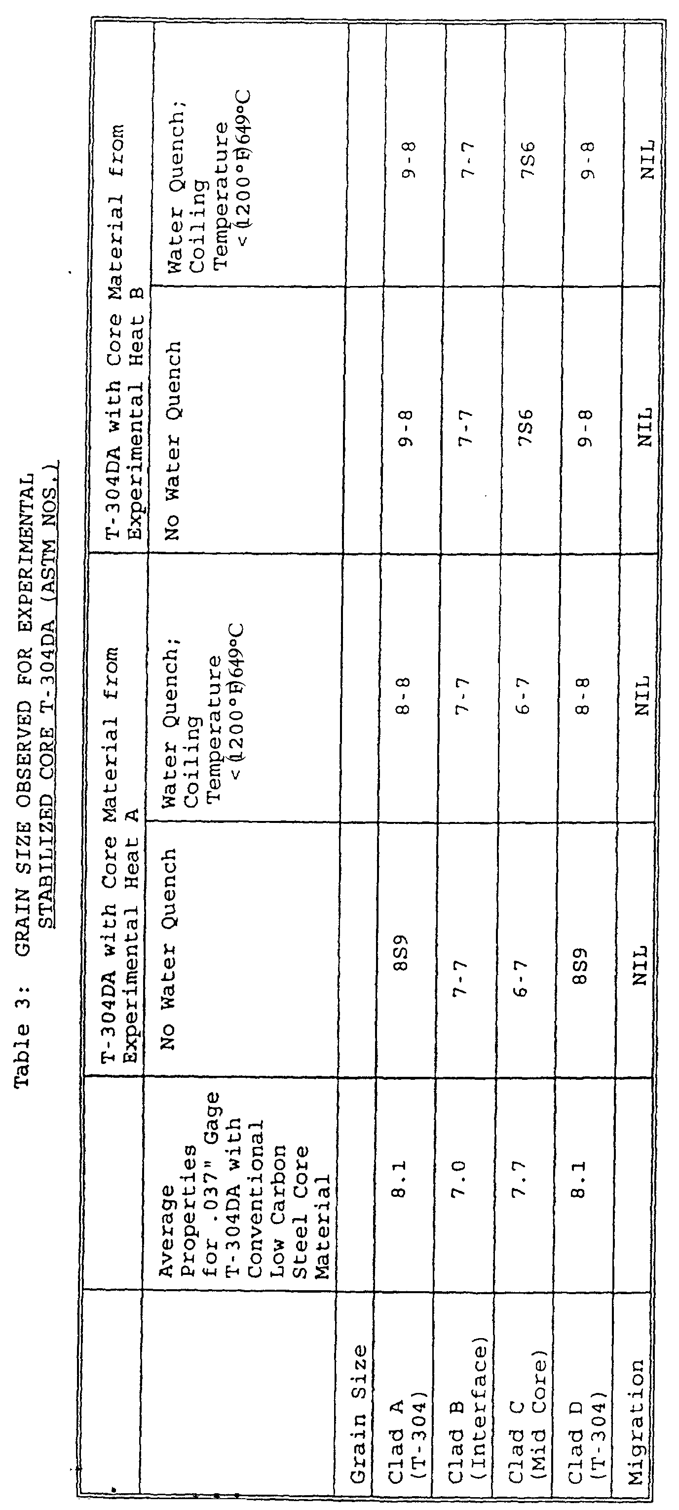
- As shown in Table 3, grain sizes throughout the experimental composites were consistent with the invention's objectives. No coarse ferrite grain layers were observed to occur upon the processing of the experimental composites. Grain sizes at all points through the finished composite compare favorably with that of a T-304DA composite which includes conventional low carbon steel core material. All grain sizes were finer than the average of the conventional T-304DA composite except at the clad C (mid-core). Also, no carbon migration into the core interface region was observed in any of the experimental samples. Consequently, no carbide enriched regions were observed in the vicinity of the interface region within the experimental samples.
- Several of the experimental coils were annealed to dissolve any carbide precipitates and allow them to re-precipitate. In order to determine satisfactory annealing temperatures and times, black band samples of the experimental T-304DA composites were cut to perform a hot band annealing study. Consistent with the objectives outlined above, the objectives of the annealing study were to (i) speed up the hot band anneal while preventing carbide formation in the stainless steel layers and (ii) maintain a fine ferrite grain size of at least ASTM #7 to #8 in the core material. The annealing study utilized temperatures in the range of 1850°F to 2100°F (1010 to 1149°C). Samples were heated to the selected anneal temperature in approximately 122 seconds and held at the anneal temperature for 0 to about 70 seconds. After the anneal procedure, the annealed samples were then water cooled to a temperature below 700°F (371°C) in 30 seconds at a cooling rate of 21.1 to 36.1°C/second (38 to 65°F/second) and evaluated for microstructure.
- The annealing experiments showed that anneals at 1010°C (1850°F) for 30 seconds, 1038°C (1900°F) for 10 seconds, or 1066°C (1950°F) for 0 seconds were sufficient to achieve the microstructural goals. These anneals ensured that the carbides in the stainless steel layers were taken into solution and that the grain size of the austenite in those layers was in the range of ASTM #8.5 to #10. Increasing the anneal temperature above 1066°C (1950°F) tended to undesirably increase the amount of coarse austenite (which transformed to widmanstatten ferrite) in the core of the T-304DA samples. Also, using an anneal temperature in excess of 1066°C (1950°F) caused the austenite grain size in the stainless steel layers to increase to ASTM #7 to #8 from the grain size ASTM #8.5 to #10 achieved at lower anneal temperatures.
- In accordance with the present invention, the hot rolled anneal can be done in shorter time within the range of 1010°C (1850°F) up to 1066°C (1950°F). The annealing experiments demonstrated that a time-at-temperature of 30 seconds at 1010°C (1850°F), and less time at higher temperatures, was sufficient to ensure that carbides in the stainless steel layers were taken into solution. As a result, the hot rolled band anneal line speeds can be increased significantly. Representative examples are illustrated in Figures 2 and 3. Figure 2 is representative of a time-temperature plot of the prior practice of hot rolled band anneal. The prior practice hot band anneal uses 1066°C (1950°F) zone temperatures with a strip speed of 0.14 m/s (28 feet per minute (fpm)). The strip is at a temperature greater than 1010°C (1850°F) for 110 seconds with a maximum temperature of 1060°C (1940°F). The cooling rate is 25 to 36.1°C/second (45 to 65°F/second). Figure 3 illustrates the faster anneal cycle of the present invention. The faster anneal cycle uses 1093°C (2000°F) in the preheat zones and 1079°C (1975°F) in the heating zones with a strip speed of 0.2m/s (40 FPM). The strip is at a temperature greater than 1010°C (1850°F) for 64 seconds with a maximum temperature of 1054°C (1930°F). The cooling rate is 33.3 to 50°C/second (60 to 90°F/second).
- Although the faster anneal cycle is preferably used with the stabilized carbon steel core of the present invention, it has been found to be useful even with conventional carbon steel/stainless steel composites.
- As was the object of the present invention, a modified carbon steel/stainless steel composite is provided having a reduced propensity for the formation of carbide enriched areas in the interface and having finer grain size in the carbon steel core. The modified core chemistry permits the composite to be coiled at higher temperatures after hot rolling with a reduced incidence of mechanical defects. The composite also has the benefit of no requirement for skin pass rolling to eliminate the stretcher strains common in composites using conventional carbon steel core materials.
Claims (7)
- A pressure-bonded composite material comprising at least one layer of stainless steel bonded to at least one layer of a stabilized carbon steel along an interface, said stabilized carbon steel including niobium and at least one or more other carbide-forming elements in amounts effective to prevent carbon migration from said stabilized carbon steel so that said interface is substantially free from enriched carbide regions, and wherein said layers of stainless steel and stabilized carbon steel have a physical grain size no larger than ASTM #6, said stabilized carbon steel comprising the following elements by weight percent of the total weight of stabilized carbon steel:no more than about 0.008% nitrogen; and0.01 to 0.025% carbon;0.07 to 0.09% titanium;0.02 to 0.04% niobium;
the balance iron and incidental impurities. - A pressure-bonded composite material according to claim 1 wherein said stabilized carbon steel includes at least one other carbide-forming element selected from the group consisting of tantalum, and zirconium.
- A pressure-bonded composite material according to claim 1 or 2, wherein said composite material has a yield strength less than about 414Mpa (60 ksi) and an elongation greater than 45 %.
- A pressure-bonded composite material according to any one of the preceding claims wherein said stabilized carbon steel layer comprises the following elements by weight percent of the total weight of stabilized carbon steel:no more than about 0.005% nitrogen; and0.01 to 0.02% carbon;0.07 to 0.09% titanium;0.02 to 0.04% niobium;
the balance iron and incidental impurities. - A method for producing a pressure-bonded composite material comprising the steps of producing a hot-rolled band of a composite material, said composite material comprising at least one layer of stainless steel bonded to at least one layer of a stabilized carbon steel, coiling the hot-rolled band at a temperature greater than about 760°C (1400°F), said stabilized carbon steel comprising the following elements by weight percent of the total weight of stabilized carbon steel:no more than about 0.008% nitrogen; and0.01 to 0.025% carbon;0.07 to 0.09% titanium;0.02 to 0.04% niobium;
the balance iron and incidental impurities. - A method according to claim 5 wherein the stabilized carbon steel comprises the following elements by weight percent of the total weight of stabilized carbon steel:no more than about 0.005% nitrogen; and0.01 to 0.02 % carbon;0.07 to 0.09% titanium;0.02 to 0.04% niobium;
the balance iron, and incidental impurities. - A method according to claim 5 or 6, further including annealing the hot rolled band at a temperature of between about 1010°C (1850°F) and about 1066°C (1950°F) for a time as low as 30 seconds at 1010°C (1850°F).
Applications Claiming Priority (2)
| Application Number | Priority Date | Filing Date | Title |
|---|---|---|---|
| US08/040,791 US5370946A (en) | 1993-03-31 | 1993-03-31 | Stainless steel and carbon steel composite |
| US40791 | 1993-03-31 |
Publications (2)
| Publication Number | Publication Date |
|---|---|
| EP0618067A1 EP0618067A1 (en) | 1994-10-05 |
| EP0618067B1 true EP0618067B1 (en) | 2002-01-09 |
Family
ID=21912973
Family Applications (1)
| Application Number | Title | Priority Date | Filing Date |
|---|---|---|---|
| EP94301532A Expired - Lifetime EP0618067B1 (en) | 1993-03-31 | 1994-03-03 | Stainless steel and carbon steel composite, and method of producing the same |
Country Status (12)
| Country | Link |
|---|---|
| US (2) | US5370946A (en) |
| EP (1) | EP0618067B1 (en) |
| JP (1) | JP3596905B2 (en) |
| KR (1) | KR100242875B1 (en) |
| CN (1) | CN1039889C (en) |
| AT (1) | ATE211684T1 (en) |
| BR (1) | BR9401316A (en) |
| CA (1) | CA2116144C (en) |
| DE (1) | DE69429592T2 (en) |
| ES (1) | ES2170086T3 (en) |
| FI (1) | FI108413B (en) |
| TW (1) | TW313593B (en) |
Families Citing this family (11)
| Publication number | Priority date | Publication date | Assignee | Title |
|---|---|---|---|---|
| FR2690166A1 (en) * | 1992-04-16 | 1993-10-22 | Creusot Loire | A method of manufacturing a plated sheet having an abrasion-resistant layer of tool steel and plated sheet obtained. |
| US5896241A (en) * | 1996-08-07 | 1999-04-20 | Imation Corp. | Plain carbon steel hub for data storage device |
| US6783871B2 (en) * | 2002-04-05 | 2004-08-31 | Agilent Technologies, Inc. | Direct bond of steel at low temperatures |
| WO2007055764A2 (en) * | 2005-11-07 | 2007-05-18 | William Russell Kingston | Metal laminate |
| US20100108690A1 (en) * | 2008-08-12 | 2010-05-06 | All-Clad Metalcrafters Llc | Stainless Steel-Carbon Steel Enamelized Cookware |
| CN101947870B (en) * | 2010-11-01 | 2012-10-03 | 山东大学 | Corrosion-resistant rod composite material and preparation method thereof |
| US10071863B2 (en) | 2013-03-15 | 2018-09-11 | Mark E. Koenig | Method for processing material for a gasifier |
| US10190065B2 (en) | 2013-03-15 | 2019-01-29 | Mark E. Koenig | Feed delivery system and method for gasifier |
| CN112877589B (en) * | 2019-11-29 | 2022-03-18 | 宝山钢铁股份有限公司 | Carbon steel austenitic stainless steel rolled composite plate and manufacturing method thereof |
| CN113444865A (en) * | 2021-05-10 | 2021-09-28 | 北京交通大学 | Heat treatment process method of duplex stainless steel-carbon steel composite plate |
| CN119913429A (en) * | 2023-10-31 | 2025-05-02 | 宝山钢铁股份有限公司 | A corrosion-resistant rolled composite steel plate for medium-temperature equipment and a manufacturing method thereof |
Family Cites Families (15)
| Publication number | Priority date | Publication date | Assignee | Title |
|---|---|---|---|---|
| US3693242A (en) * | 1970-01-02 | 1972-09-26 | Allegheny Ludlum Steel | Composite material and production thereof |
| US3795971A (en) * | 1970-01-02 | 1974-03-12 | J Chivinsky | Method of producing a composite material |
| US3862484A (en) * | 1970-01-02 | 1975-01-28 | Allegheny Ludlum Ind Inc | Production of composite material |
| US3956809A (en) * | 1972-05-30 | 1976-05-18 | Allegheny Ludlum Industries, Inc. | Pressure bonded composite material with low yield strength |
| US3944396A (en) * | 1972-08-30 | 1976-03-16 | Allegheny Ludlum Industries, Inc. | Pressure bonded, low yield strength composite |
| US4178417A (en) * | 1977-03-23 | 1979-12-11 | The Japan Steel Works, Ltd. | Clad steel |
| JPS58151425A (en) * | 1982-02-27 | 1983-09-08 | Nippon Kokan Kk <Nkk> | Method for producing highly corrosion-resistant clad steel pipes with excellent low-temperature toughness |
| US4455352A (en) * | 1982-11-08 | 1984-06-19 | The Babcock & Wilcox Company | Materials system for high strength corrosion resistant bimetallic products |
| JPS6259034A (en) * | 1985-05-29 | 1987-03-14 | 新日本製鐵株式会社 | Stainless clad steel plate having excellent workability and corrosion resistance |
| JPS6241033A (en) * | 1985-08-20 | 1987-02-23 | 三菱重工業株式会社 | High-purity ferrite group stainless clad steel |
| JPH0699757B2 (en) * | 1985-08-20 | 1994-12-07 | 新日本製鐵株式会社 | Manufacturing method of stainless clad steel plate with excellent workability and corrosion resistance |
| JPS6274025A (en) * | 1985-09-27 | 1987-04-04 | Kawasaki Steel Corp | Heat treatment for clad cold rolled steel strip |
| JPS6280223A (en) * | 1985-10-03 | 1987-04-13 | Kawasaki Steel Corp | Manufacture of austenitic stainless clad cold roller steel sheet |
| DE3742539A1 (en) * | 1987-12-16 | 1989-07-06 | Thyssen Stahl Ag | METHOD FOR PRODUCING PLATED WARM RIBBON AND FOLLOWING PRODUCED PLATED WARM RIBBON |
| JPH07103422B2 (en) * | 1988-01-14 | 1995-11-08 | 新日本製鐵株式会社 | Good workability High strength cold rolled steel sheet manufacturing method |
-
1993
- 1993-03-31 US US08/040,791 patent/US5370946A/en not_active Expired - Lifetime
-
1994
- 1994-02-22 CA CA002116144A patent/CA2116144C/en not_active Expired - Lifetime
- 1994-02-25 KR KR1019940003394A patent/KR100242875B1/en not_active Expired - Lifetime
- 1994-03-03 EP EP94301532A patent/EP0618067B1/en not_active Expired - Lifetime
- 1994-03-03 AT AT94301532T patent/ATE211684T1/en active
- 1994-03-03 ES ES94301532T patent/ES2170086T3/en not_active Expired - Lifetime
- 1994-03-03 DE DE69429592T patent/DE69429592T2/en not_active Expired - Lifetime
- 1994-03-28 BR BR9401316A patent/BR9401316A/en not_active IP Right Cessation
- 1994-03-30 TW TW083102797A patent/TW313593B/zh not_active IP Right Cessation
- 1994-03-31 FI FI941530A patent/FI108413B/en not_active IP Right Cessation
- 1994-03-31 CN CN94103913A patent/CN1039889C/en not_active Expired - Lifetime
- 1994-03-31 JP JP9785094A patent/JP3596905B2/en not_active Expired - Fee Related
-
1995
- 1995-05-30 US US08/453,929 patent/US5529644A/en not_active Expired - Lifetime
Non-Patent Citations (1)
| Title |
|---|
| HASHIMOTO: "Development of new low carbon low alloy steel suited to be clad with stainless steel.", ISIJ, vol. 31, 1991, pages 706 - 711 * |
Also Published As
| Publication number | Publication date |
|---|---|
| US5529644A (en) | 1996-06-25 |
| JP3596905B2 (en) | 2004-12-02 |
| JPH071162A (en) | 1995-01-06 |
| CN1095989A (en) | 1994-12-07 |
| DE69429592D1 (en) | 2002-02-14 |
| EP0618067A1 (en) | 1994-10-05 |
| BR9401316A (en) | 1994-11-01 |
| KR940021174A (en) | 1994-10-17 |
| CA2116144A1 (en) | 1994-10-01 |
| DE69429592T2 (en) | 2002-08-22 |
| FI108413B (en) | 2002-01-31 |
| US5370946A (en) | 1994-12-06 |
| FI941530A0 (en) | 1994-03-31 |
| FI941530L (en) | 1994-10-01 |
| CA2116144C (en) | 2001-05-01 |
| CN1039889C (en) | 1998-09-23 |
| ATE211684T1 (en) | 2002-01-15 |
| KR100242875B1 (en) | 2000-03-02 |
| TW313593B (en) | 1997-08-21 |
| ES2170086T3 (en) | 2002-08-01 |
Similar Documents
| Publication | Publication Date | Title |
|---|---|---|
| JP5729456B2 (en) | Steel material excellent in ductile crack initiation characteristics of weld heat-affected zone and base metal zone and its manufacturing method | |
| AU639446B2 (en) | Process for preparing low earing aluminum alloy strip | |
| US5370946A (en) | Stainless steel and carbon steel composite | |
| EP2199422A1 (en) | Low-carbon precipitation-strengthened steel for cold heading applications | |
| JPH0692626B2 (en) | Forging roll for hot rolling | |
| US7220325B2 (en) | High-strength micro-alloy steel | |
| US6682613B2 (en) | Process for making high strength micro-alloy steel | |
| US9587770B2 (en) | α + β type titanium alloy sheet for welded pipe, manufacturing method thereof, and α + β type titanium alloy welded pipe product | |
| JP4235132B2 (en) | Method for producing non-oriented electrical steel sheet with excellent magnetic properties | |
| EP0877825B1 (en) | Method of preparing a magnetic article from a duplex ferromagnetic alloy | |
| JPH029647B2 (en) | ||
| CA2004336C (en) | High strength non-magnetic alloy | |
| Ammon et al. | Pilot production and evaluation of tantalum alloy sheet | |
| JP5491968B2 (en) | Steel bar manufacturing method | |
| JPS6369951A (en) | Nonmagnetic austenitic stainless steel having high hardness | |
| JPH1088301A (en) | Method for producing iron-cobalt alloy plate | |
| Patel et al. | Value Creation with Dilute Additions of Niobium in Carbon Structural Steels | |
| JP2026514392A (en) | High-strength cold-rolled and annealed steel and method for manufacturing the same | |
| Rodrigues et al. | Nb-Ti Microalloyed HSLA steel structural evolution during hot rolling in pilot scale | |
| JPS5942728B2 (en) | Manufacturing method of composite roll | |
| JPH0558046B2 (en) | ||
| JPH02101119A (en) | Production of high-carbon content martensitic stainless steel having excellent impact toughness | |
| Boelen | Evidence for NbCN precipitation in undeformed austenite | |
| Stumpf et al. | Inconsistent dynamic recrystallization behaviour in boron-alloyed low carbon steels | |
| JPH0641644A (en) | Manufacture of cr-ni series stainless steel thin sheet excellent in material and surface quality |
Legal Events
| Date | Code | Title | Description |
|---|---|---|---|
| PUAI | Public reference made under article 153(3) epc to a published international application that has entered the european phase |
Free format text: ORIGINAL CODE: 0009012 |
|
| AK | Designated contracting states |
Kind code of ref document: A1 Designated state(s): AT BE DE ES FR GB IT SE |
|
| 17P | Request for examination filed |
Effective date: 19950127 |
|
| 17Q | First examination report despatched |
Effective date: 19990610 |
|
| GRAG | Despatch of communication of intention to grant |
Free format text: ORIGINAL CODE: EPIDOS AGRA |
|
| GRAG | Despatch of communication of intention to grant |
Free format text: ORIGINAL CODE: EPIDOS AGRA |
|
| GRAH | Despatch of communication of intention to grant a patent |
Free format text: ORIGINAL CODE: EPIDOS IGRA |
|
| RAP1 | Party data changed (applicant data changed or rights of an application transferred) |
Owner name: ATI PROPERTIES, INC. |
|
| 111L | Licence recorded |
Free format text: 20010720 0100 ALLEGHENY LUDLUM CORPORATION |
|
| GRAH | Despatch of communication of intention to grant a patent |
Free format text: ORIGINAL CODE: EPIDOS IGRA |
|
| GRAA | (expected) grant |
Free format text: ORIGINAL CODE: 0009210 |
|
| REG | Reference to a national code |
Ref country code: GB Ref legal event code: IF02 |
|
| AK | Designated contracting states |
Kind code of ref document: B1 Designated state(s): AT BE DE ES FR GB IT SE |
|
| REF | Corresponds to: |
Ref document number: 211684 Country of ref document: AT Date of ref document: 20020115 Kind code of ref document: T |
|
| REF | Corresponds to: |
Ref document number: 69429592 Country of ref document: DE Date of ref document: 20020214 |
|
| ET | Fr: translation filed | ||
| REG | Reference to a national code |
Ref country code: ES Ref legal event code: FG2A Ref document number: 2170086 Country of ref document: ES Kind code of ref document: T3 |
|
| PLBE | No opposition filed within time limit |
Free format text: ORIGINAL CODE: 0009261 |
|
| STAA | Information on the status of an ep patent application or granted ep patent |
Free format text: STATUS: NO OPPOSITION FILED WITHIN TIME LIMIT |
|
| 26N | No opposition filed | ||
| PGFP | Annual fee paid to national office [announced via postgrant information from national office to epo] |
Ref country code: IT Payment date: 20120327 Year of fee payment: 19 |
|
| PGFP | Annual fee paid to national office [announced via postgrant information from national office to epo] |
Ref country code: SE Payment date: 20130327 Year of fee payment: 20 Ref country code: DE Payment date: 20130327 Year of fee payment: 20 Ref country code: FR Payment date: 20130405 Year of fee payment: 20 Ref country code: GB Payment date: 20130327 Year of fee payment: 20 Ref country code: ES Payment date: 20130326 Year of fee payment: 20 |
|
| PGFP | Annual fee paid to national office [announced via postgrant information from national office to epo] |
Ref country code: AT Payment date: 20130220 Year of fee payment: 20 |
|
| PGFP | Annual fee paid to national office [announced via postgrant information from national office to epo] |
Ref country code: BE Payment date: 20130327 Year of fee payment: 20 |
|
| REG | Reference to a national code |
Ref country code: DE Ref legal event code: R071 Ref document number: 69429592 Country of ref document: DE |
|
| REG | Reference to a national code |
Ref country code: GB Ref legal event code: PE20 Expiry date: 20140302 |
|
| BE20 | Be: patent expired |
Owner name: *ATI PROPERTIES INC. Effective date: 20140303 |
|
| REG | Reference to a national code |
Ref country code: AT Ref legal event code: MK07 Ref document number: 211684 Country of ref document: AT Kind code of ref document: T Effective date: 20140303 |
|
| REG | Reference to a national code |
Ref country code: SE Ref legal event code: EUG |
|
| PG25 | Lapsed in a contracting state [announced via postgrant information from national office to epo] |
Ref country code: DE Free format text: LAPSE BECAUSE OF EXPIRATION OF PROTECTION Effective date: 20140304 Ref country code: GB Free format text: LAPSE BECAUSE OF EXPIRATION OF PROTECTION Effective date: 20140302 |
|
| REG | Reference to a national code |
Ref country code: ES Ref legal event code: FD2A Effective date: 20140925 |
|
| REG | Reference to a national code |
Ref country code: ES Ref legal event code: FD2A Effective date: 20140926 |
|
| PG25 | Lapsed in a contracting state [announced via postgrant information from national office to epo] |
Ref country code: ES Free format text: LAPSE BECAUSE OF EXPIRATION OF PROTECTION Effective date: 20140304 |