EP0617759B1 - Reverse phase and high discharge temperature protection in a scroll compressor - Google Patents
Reverse phase and high discharge temperature protection in a scroll compressor Download PDFInfo
- Publication number
- EP0617759B1 EP0617759B1 EP92925204A EP92925204A EP0617759B1 EP 0617759 B1 EP0617759 B1 EP 0617759B1 EP 92925204 A EP92925204 A EP 92925204A EP 92925204 A EP92925204 A EP 92925204A EP 0617759 B1 EP0617759 B1 EP 0617759B1
- Authority
- EP
- European Patent Office
- Prior art keywords
- discharge
- compressor
- gas
- passage
- pressure portion
- Prior art date
- Legal status (The legal status is an assumption and is not a legal conclusion. Google has not performed a legal analysis and makes no representation as to the accuracy of the status listed.)
- Expired - Lifetime
Links
Images

Classifications
-
- F—MECHANICAL ENGINEERING; LIGHTING; HEATING; WEAPONS; BLASTING
- F04—POSITIVE - DISPLACEMENT MACHINES FOR LIQUIDS; PUMPS FOR LIQUIDS OR ELASTIC FLUIDS
- F04C—ROTARY-PISTON, OR OSCILLATING-PISTON, POSITIVE-DISPLACEMENT MACHINES FOR LIQUIDS; ROTARY-PISTON, OR OSCILLATING-PISTON, POSITIVE-DISPLACEMENT PUMPS
- F04C28/00—Control of, monitoring of, or safety arrangements for, pumps or pumping installations specially adapted for elastic fluids
- F04C28/28—Safety arrangements; Monitoring
-
- F—MECHANICAL ENGINEERING; LIGHTING; HEATING; WEAPONS; BLASTING
- F04—POSITIVE - DISPLACEMENT MACHINES FOR LIQUIDS; PUMPS FOR LIQUIDS OR ELASTIC FLUIDS
- F04C—ROTARY-PISTON, OR OSCILLATING-PISTON, POSITIVE-DISPLACEMENT MACHINES FOR LIQUIDS; ROTARY-PISTON, OR OSCILLATING-PISTON, POSITIVE-DISPLACEMENT PUMPS
- F04C2270/00—Control; Monitoring or safety arrangements
- F04C2270/19—Temperature
-
- F—MECHANICAL ENGINEERING; LIGHTING; HEATING; WEAPONS; BLASTING
- F04—POSITIVE - DISPLACEMENT MACHINES FOR LIQUIDS; PUMPS FOR LIQUIDS OR ELASTIC FLUIDS
- F04C—ROTARY-PISTON, OR OSCILLATING-PISTON, POSITIVE-DISPLACEMENT MACHINES FOR LIQUIDS; ROTARY-PISTON, OR OSCILLATING-PISTON, POSITIVE-DISPLACEMENT PUMPS
- F04C2270/00—Control; Monitoring or safety arrangements
- F04C2270/70—Safety, emergency conditions or requirements
-
- F—MECHANICAL ENGINEERING; LIGHTING; HEATING; WEAPONS; BLASTING
- F04—POSITIVE - DISPLACEMENT MACHINES FOR LIQUIDS; PUMPS FOR LIQUIDS OR ELASTIC FLUIDS
- F04C—ROTARY-PISTON, OR OSCILLATING-PISTON, POSITIVE-DISPLACEMENT MACHINES FOR LIQUIDS; ROTARY-PISTON, OR OSCILLATING-PISTON, POSITIVE-DISPLACEMENT PUMPS
- F04C2270/00—Control; Monitoring or safety arrangements
- F04C2270/70—Safety, emergency conditions or requirements
- F04C2270/72—Safety, emergency conditions or requirements preventing reverse rotation
-
- F—MECHANICAL ENGINEERING; LIGHTING; HEATING; WEAPONS; BLASTING
- F05—INDEXING SCHEMES RELATING TO ENGINES OR PUMPS IN VARIOUS SUBCLASSES OF CLASSES F01-F04
- F05B—INDEXING SCHEME RELATING TO WIND, SPRING, WEIGHT, INERTIA OR LIKE MOTORS, TO MACHINES OR ENGINES FOR LIQUIDS COVERED BY SUBCLASSES F03B, F03D AND F03G
- F05B2270/00—Control
- F05B2270/30—Control parameters, e.g. input parameters
- F05B2270/303—Temperature
- F05B2270/3032—Temperature excessive temperatures, e.g. caused by overheating
Definitions
- This invention relates generally to the protection of scroll compressors from damage due to the existence of abnormal operating conditions.
- Hermetic compressors including those of the scroll type, are of a high or a low side type.
- a high side compressor is one in which the motor is disposed in the discharge or high pressure portion of the compressor shell.
- a low side compressor is one in which the motor is disposed in the suction or low pressure portion of the hermetic shell.
- This backflow is as a result of the natural tendency of the system within which the compressor is employed to equalize its internal pressure when the compressor is de-energized.
- Such backflow if not prevented, can cause the high speed reverse rotation of the compression mechanism and can lead to potentially serious compressor damage.
- the prevention of such backflow upon compressor shutdown is typically accomplished by the disposition of a discharge check valve downstream of the aperture through which gas is discharged from the compressor's compression mechanism.
- the discharge check valve is closed by the initial backflow of refrigerant gas through the compressor which begins immediately upon compressor shutdown.
- the closing of the discharge check valve may be assisted or accelerated by a biasing member such as a spring.
- the scroll device functions as a gas expander or pump as opposed to a compressor.
- Still another difficulty and potential source for damage in scroll compressors is the development of high discharge gas temperatures in operation.
- Such high discharge temperatures can result from, among other things, the operation of the compressor in a system where pressure ratios develop that are outside of the compressor's normal operating range.
- Such high discharge gas temperatures can cause thermal growth within the compressor, and, in particular, thermal growth of the scroll wraps.
- the thermal expansion of the scroll wraps can lead to high wrap tip contact loads and the galling of the wrap tips.
- Compressor protection with respect to the development of high discharge temperatures has historically involved the disposition of a temperature sensor on a discharge line leading from the compressor's hermetic shell or the disposition of an internally mounted temperature sensor closely proximate to the location at which discharge gas issues from between the scroll wraps into the discharge portion of the compressor shell.
- the former arrangement can be inadequate because the externally mounted sensor, which is remote from the critical scroll wrap location, may not sense the existence of high discharge temperatures sufficiently early to prevent damage to the scroll members.
- the need continues to exist to protect hermetic scroll compressors of the low side type from the damage which can result from their improper electrical hookup or from the occurrence of high discharge temperatures, while eliminating the need to position a temperature sensor in the discharge portion of the compressor shell and the need to route sensor leads through or out of the shell's discharge pressure portion.
- US-A-4840545 is concerned with preventing damage to a scroll compressor due to reverse rotation of the scroll members thereof and discloses an apparatus for compressing a gas comprising:
- the invention provides apparatus for compressing a gas comprising:
- the flow permitting means includes means defining a passage internal of said shell which communicates between said suction pressure portion and said discharge pocket.
- the flow permitting means may include a valve member, said valve member being actuated to permit said gas flow through said passage (i) by the development of gas pressure in said discharge pocket less than gas pressure in said suction pressure portion and (ii) by the occurrence of discharge gas temperatures which exceed said predetermined temperature.
- the valve member may be a thermally responsive bimetal valve.
- valve member is disposed entirely within said passage and is not connected to any other element of the apparatus.
- the bimetal valve member responds to discharge temperatures which exceed said predetermined temperature by changing shape to permit said gas flow from said discharge pocket to said suction pressure portion.
- the apparatus may further comprise means for preventing backflow of gas from said discharge pressure portion of the shell to said discharge pocket when the pressure in said discharge pocket is less than the pressure in said discharge pressure portion.
- the passage may have one end disposed within said shell at a location upstream of said backflow preventing means.
- the passage may communicate with said discharge pocket via an opening upstream of said backflow preventing means.
- the backflow preventing means may be disposed downstream of said discharge pressure portion of the shell.
- the passage may be at least partially defined by a fixed one of said scroll members.
- the apparatus may further comprise a motor for driving one of said first and second scroll members, said motor being disposed in said suction pressure portion of the shell.
- the passage may open into said suction pressure portion of the shell adjacent a thermally actuated protective device for de-energising said motor when exposed to temperatures exceeding said predetermined temperature.
- the thermally actuated protective device may be a line break which is integral to said motor.
- the invention includes a method for protecting a scroll compressor against damage due to reverse direction motor rotation or high discharge temperatures, the method comprising the steps of defining a passage in said compressor, said passage communicating between a suction pressure portion of said compressor and a portion of said compressor through which discharge gas flows when said compressor is in normal operation, and controlling flow through said passage such that: (i) gas is permitted to flow through said passage from said suction pressure portion to said portion of said compressor through which discharge gas normally flows when the pressure in said suction pressure portion exceeds the pressure in said portion of said compressor through which discharge gas normally flows; (ii) gas is permitted to flow through said passage from said portion of said compressor through which discharge gas normally flows to said suction pressure portion of said compressor when the temperature of said gas exceeds a predetermined temperature; and (iii) gas is prevented from flowing through said passage when said discharge temperature is less than said predetermined temperature and when the pressure in said portion of said compressor through which discharge gas normally flows exceeds the pressure in said suction pressure portion.
- the method may comprise the step of disposing a thermally responsive valve in said passage.
- the scroll compressor includes a motor disposed in said suction pressure portion of said shell, the method further comprising the step of disposing a thermally actuated motor protective device adjacent the location where said passage opens into said suction pressure portion of said shell.
- the method may comprise the step of fabricating said valve from a bimetal so that said valve responds to temperatures in excess of said predetermined temperature by changing shape, the change of shape of said valve opening said passage to gas flow when discharge gas temperatures exceed said predetermined temperature.
- the fabricating step may include the step of sizing said valve such that when disposed in said passage the valve is free to move within a predetermined portion of said passage and is not connected to said compressor.
- compressor 20 has a hermetic shell 22, in which a fixed scroll member 24 is disposed.
- Fixed scroll member 24 defines a discharge aperture 26 and has an involute wrap 28 extending from it.
- An orbiting scroll member 30 is likewise disposed in shell 22 and likewise has an extending involute wrap 32 which is disposed in interleaving engagement with the involute wrap 28 of fixed scroll member 24.
- Scroll members 24 and 30 and their interleaved involute wraps 28 and 32 cooperate to define a plurality of pockets therebetween.
- the volume of the pockets decrease as they move in a radially inward direction toward discharge aperture 26 when compressor 20 is in normal operation.
- the pockets and their movement are created by the relative orbital motion of the scroll members.
- Discharge pocket 34 is the radially innermost pocket defined by the scroll members and is in flow communication with discharge aperture 26 of the fixed scroll member.
- Fixed scroll member 24 serves to divide hermetic shell 22 into a discharge pressure portion 36 and a suction pressure portion 38. It should be understood that the division of hermetic shell 22 into a discharge pressure portion 36 and suction pressure portion 38 can be accomplished by means other than the use of fixed scroll member 24 such as by the use of an independent barrier or seal member.
- a suction port 40 is provided to permit gas at suction pressure to enter suction pressure portion 38 of hermetic shell 22. Suction gas enters the radially outermost pocket defined by the scroll members, which is cyclically formed and closed by the orbital movement of the orbiting scroll member with respect to the fixed scroll member.
- a discharge port 42 is provided in shell 22 to permit the discharge of compressed gas from the discharge portion 36 of the compressor.
- a protective arrangement for the compressor 20 comprises means adapted for selectively permitting flow between the suction pressure portion 38 and the discharge pocket 34 which flow permitting means comprises a passage 46 in which a valve member 48 is disposed.
- the passage 46 comprises passage portions 46a and 46b interconnected by a chamber 62.
- Compressor 20 is driven by an electric motor 50 which is disposed in the suction pressure portion 38 of shell 22 and is therefore a low-side compressor.
- Motor 50 includes a stator 52 and rotor 54.
- a drive shaft 56 connects motor rotor 54 and orbiting scroll member 28 through a swing link mechanism 58.
- Motor 50 includes a thermally actuated line break device 60 associated with stator 52. The line break device is disposed adjacent the opening of passage 46 into suction pressure portion 38 of the compressor shell.
- compressor 20 is illustrated as including a swing link mechanism, it should be understood that the present invention is equally applicable to scroll compressors which do not make use of swing link apparatus including scroll compressors of the fixed throw type. It must also be understood that although device 60 is preferably a thermally actuated line break device which is integral with the compressor motor, other thermally actuated devices are suitable for use and are within the scope of the present invention.
- Compressor 20 includes means, operable when the pressure in discharge pressure portion 36 of shell 22 exceeds the pressure in discharge pocket 34 (such as upon compressor shutdown), for preventing the backflow of refrigerant gas from discharge pressure portion of the shell back through passage 44 and into discharge pocket 34 between the scroll members.
- such means are a discharge check valve assembly 100 which is disposed atop fixed scroll member 24.
- Discharge check valve assembly 100 is comprised of a stop member 120 which is fixedly disposed between guide posts 130 as is best illustrated in Figure 3.
- Valve assembly 100 includes a free-floating valve element 140 which operates between a closed position in which it seats over and closes passage 44 from discharge portion 36 and an open position in which the flow of discharge gas through passage 44 lifts the valve element upward so that it seats against stop member 120.
- valve element 140 When compressor 20 is shut down and pressures within shell 22 are equalized, valve element 140 rests over discharge passage 44, as is illustrated in Figure 2, and is maintained there by force of gravity. When compressor 22 starts and discharge gas begins to flow through passage 44 from pocket 34, the flow of the compressed gas lifts valve element 140 and maintains it in the open position resting against stop member 120 as is illustrated in Figure 4.
- valve element 140 will be in its closed position whenever the compressor is at rest, including those instances where the compressor has not yet been initially wired or has been electrically disconnected, it will be appreciated that if motor 50 is initially or subsequently miswired such that orbiting scroll member 28 is driven in a direction opposite from that which is intended, the pockets defined by the scroll member, including discharge pocket 34 will be caused to expand and move radially outward. As a result, compressor 20 will function, in effect, as an expander.
- the scroll members will act against the closed discharge check valve assembly 100 so that pressure in the compression pockets, including discharge pocket 34, is pulled down and becomes less than suction pressure.
- the pressure may, in fact, approach vacuum because closed valve element 140 prevents the flow of gas from the discharge pressure portion of the compressor and eliminates a souce of gas from which the miswired apparatus can pump. Under such conditions, the tips of the wraps of the scroll members are drawn into exceedingly high frictional contact with the opposing scroll member and severe compressor damage can occur.
- the compressor can be damaged by exceedingly high discharge temperatures which can occur, for instance, due to operation of the compressor at pressure ratios outside of its normal operating range. Such temperatures can cause thermal growth of the scroll members, particularly in their wraps, with the result that contact loads on the tips of the scroll members become exceedingly high.
- compressor 20 will function as an expander.
- the expansion of the compression pockets, including discharge pocket 34, causes a reduction in pressure in those pockets such that pressures less than suction pressure will occur within the pockets in a very short time.
- discharge pocket 34 is open to discharge passage 44 which, under such circumstances, is closed off from the discharge pressure portion of the compressor by the seating of valve element 140 over passage 44, the development of a sub-suction pressure within discharge pocket 34 will result in the development of sub-suction pressures both in discharge passage 44 and in the portion 46a of passage 46.
- Passage portion 46a is on the discharge pressure side of valve member 48 and opens into passage 44.
- Valve member 48 is an otherwise free-floating element within the chamber 62 and is unconnected to any other compressor element. Chamber 62 in this embodiment is closed such as by plugs 64a and 64b and can be characterized as an enlarged portion of the passage 46.
- valve member 48 upon the occurrence of even a slight pressure differential across free-floating valve member 48, as would be indicative of the development of sub-suction pressure in the discharge pocket defined by the scroll wraps, suction pressure gas will quickly begin to flow through passage 46 and into discharge pocket 34 to prevent the development of excessive contact loads on the scroll wrap tips.
- valve member 48 At such time as pressure greater than suction pressure comes to exist in discharge pocket 34 and discharge passage 44, such as by the proper wiring of the compressor and the resulting compression of gas between the scroll members, valve member 48 will be caused to seat within chamber 62 by discharge pressure gas and will prevent the flow of gas through passage 46 under what amounts to a normal operating condition.
- valve member 48 is a bimetal valve comprised of two layers 48a and 48b of dissimilar metals the thermal expansion rates of which are dissimilar.
- the metals selected for the fabrication of valve member 48 are selected in accordance with their thermal expansion characteristics so that when the valve member is heated the differing expansion rates of the dissimilar metals will cause the valve to deform in the manner of a diaphragm.
- Valve member 48 has a generally circular portion the facial area of which is greater than the cross sectional area of passage portion 46b.
- the valve member preferably has three legs such that when it deforms, or diaphragms, due to being exposed to gas which is at an abnormally high temperature, the legs of the valve member are maintained in contact with the interior of chamber 62.
- the spaces created between the legs of the diaphragmed valve member under such circumstances permit the passage of the abnormally hot discharge pressure gas between them and into passage portion 46b.
- the gas then flows into suction pressure portion 38 of the compressor shell. It will be appreciated that given the direction of gas flow described under these circumstances the flow of gas, along with the force of gravity, will maintain the legs of valve member 48 in contact with an interior surface of chamber 62 as illustrated.
- Passage portion 46b opens into suction pressure portion 38 of compressor shell 22 at a location proximate to motor stator 52 and the location on motor stator 52 where thermally actuated line break device 60 is disposed.
- the discharge gas will flow through passage 46, past diaphragmed valve member 48, and will issue into the suction pressure portion of the compressor.
- the hot discharge gas issuing from passage portion 46b will cause thermally actuated line break device 60 to be heated to a point where electrical continuity within the motor will be interrupted and the motor will be de-energized.
- the thermal characteristics of valve member 48 and line break 60 are selected to ensure their operation and the shutdown of the motor before discharge temperatures reach levels which can potentially cause damage to the compressor.
- the protective arrangement of the compressor 20 eliminates the need to dispose a discharge temperature sensor in the discharge pressure portion of the compressor in close proximity to discharge chamber 34 or to the discharge check valve assembly. It also eliminates the need to penetrate shell 22 or fixed scroll member 24 with sensor wiring.
- protective arrangement is equally applicable to compressors which do not have an internal discharge check valve assembly such as where a discharge check valve is disposed downstream of the discharge pressure portion of the compressor shell. If the discharge check valve assembly is located downstream of the discharge pressure portion of the compressor shell it will be appreciated that protective passage 46, which in net effect is a passage between a discharge pressure and a suction pressure portion of the compressor, can be located anywhere within the compressor so long as it opens both into the discharge and suction pressure portions of the compressor shell.
- FIG. 9 One such alternative protective arrangement is illustrated in Figure 9.
- the discharge check valve 100' of this arrangement is schematically illustrated as being disposed in discharge port element 42'.
- the alternative protective arrangement comprises means adapted for selectively permitting gas flow between the suction pressure portion 38' and the discharge pocket 34' which flow permitting means comprises a passage 46' which is illustrated as an essentially straight passage through the fixed scroll member 24' and includes a chamber 62'.
- the flow permitting means further comprises a valve member 48' disposed in the chamber 62'.
- Figure 10 illustrates that protective bimetal valve member 48' is disposed and confined, in a free-floating manner, in a chamber 62'. Chamber 62', in this arrangement, is open directly to the discharge pressure portion 36' of the shell and therethrough to passage 44' and pocket 34'.
- valve member 48' is retained in chamber 62' by a retainer insert 66'.
- the compressor protecting arrangement of Figures 9 and 10 operates on the same principles as the arrangement disclosed in Figures 1-8 including the opening of passage 46' into suction pressure portion 38' adjacent thermally actuated line break device 60'.
- a scroll compressor is provided with a protective arrangement which selectively permits the flow of refrigerant gas (i.) in a first direction within the compressor in response to the development of high compressor discharge temperatures and (ii.) in the opposite direction within the compressor in response to the reverse direction rotation of the driven scroll member but which (iii.) prevents any such flow under normal compressor operating conditions.
- Such permitted internal refrigerant flow during other than normal operating conditions is through an interruptable passage within the shell of the compressor that communicates between the suction pressure portion of the shell and a portion of the compressor through which discharge gas flows during normal operation.
- the controlled internal refrigerant flow permitted by the protective arrangement prevents compressor damage which would otherwise result from the development of high discharge temperatures or the development of sub-suction pressures between the scroll members such as can result from reverse direction compressor motor rotation. When the circumstances of high discharge temperature or sub-suction pressures between the scroll members do not exist, refrigerant flow through the internal passage is prevented.
- the protective valve member is disposed in the passage which is arranged to communicate between the suction portion of the compressor shell and a location downstream of the aperture through which compressed gas is discharged from between the scroll members in normal operation.
- the valve member is, however, located upstream of the discharge check valve which operates to cut off the backflow of compressed gas through the compressor upon normal compressor shutdown.
- the protective valve member is preferably a free-floating bimetal valve which, as described above, is unconnected to any other compressor element, and is disposed in an enlarged portion of the internal refrigerant passage.
- the protective valve member is lifted by the flow of gas from the suction pressure portion of the compressor through the passage which occurs when a pressure gradient develops across the valve member.
- Such a pressure gradient across the valve member will develop under circumstances which include the reverse direction rotation of the driven scroll member and the operation of the compressor as an expander as explained above.
- Such protective refrigerant flow through the passage will be from the suction portion of the compressor shell, through the passage in which the bimetal valve is disposed and back to a pocket defined by the scroll members. This will result in general pressure equalization between the pockets defined by the scroll members and the suction pressure portion of the compressor.
- the compressor acting as an expander, will pump from suction back to suction so long as the improper reverse direction motor rotation continues. In net effect, the compression apparatus is short-circuited under such circumstances by the lifting of the protective valve member in a manner which prevents damage to the scroll members.
- the bimetal valve Upon the occurrence of abnormally high discharge temperatures, the bimetal valve, which is normally exposed to compressor discharge gas through the passage in which it is disposed, deforms in the manner of a diaphragm which permits the venting of discharge gas around it and through the passage back to the suction pressure portion.
- the motor protection device By positioning the passage, where it opens into the suction pressure portion of the compressor, to be near a thermally actuated motor protection device, the motor protection device can be quickly actuated to shut the compressor down under high discharge temperature condition.
- the compressor is therefore protected from high discharge temperatures in a manner which does not require the use of a temperature sensor disposed in the discharge portion of the shell or the routing of sensor leads out of that portion of the compressor.
Landscapes
- Engineering & Computer Science (AREA)
- Mechanical Engineering (AREA)
- General Engineering & Computer Science (AREA)
- Applications Or Details Of Rotary Compressors (AREA)
- Rotary Pumps (AREA)
Abstract
Description
- This invention relates generally to the protection of scroll compressors from damage due to the existence of abnormal operating conditions.
- Hermetic compressors, including those of the scroll type, are of a high or a low side type. A high side compressor is one in which the motor is disposed in the discharge or high pressure portion of the compressor shell. A low side compressor is one in which the motor is disposed in the suction or low pressure portion of the hermetic shell.
- A common problem in hermetic rotary compressors, including those of the scroll type, is the tendency of compressed refrigerant gas to flow back from the discharge pressure portion of the compressor shell, through the compression mechanism and back to the suction side of the shell upon compressor shutdown. This backflow is as a result of the natural tendency of the system within which the compressor is employed to equalize its internal pressure when the compressor is de-energized. Such backflow, if not prevented, can cause the high speed reverse rotation of the compression mechanism and can lead to potentially serious compressor damage.
- The prevention of such backflow upon compressor shutdown is typically accomplished by the disposition of a discharge check valve downstream of the aperture through which gas is discharged from the compressor's compression mechanism. The discharge check valve is closed by the initial backflow of refrigerant gas through the compressor which begins immediately upon compressor shutdown. The closing of the discharge check valve may be assisted or accelerated by a biasing member such as a spring.
- In scroll compressors having compression mechanisms which are protected from gas-driven reverse rotation by apparatus such as a discharge check valve, a problem arises when the compressor is electrically connected in an improper manner. Such improper electrical connection can cause the motor to run in a direction reverse from which it is intended to run. This problem is recognized in U.S. Patents 4,820,130 and 4,840,545, both of which are assigned to the assignee of the present invention.
- Briefly, when a scroll compressor having a discharge check valve is miswired so that it is caused to run backwards, the pockets defined between the scroll wraps, instead of moving radially inward and decreasing in volume, move radially outward and expand in volume in a pumping action. In effect, the scroll device functions as a gas expander or pump as opposed to a compressor.
- The expansion of the pockets defined by the scroll members under such circumstances causes low and even negative pressures to develop within the pockets because the discharge check valve, being closed, gives the mechanism no source of gas to pump from. As a result, the scroll members are drawn tightly together which can eventually result, to the extent the compressor motor continues to run backwards, in severe damage and possibly destruction of the compressor.
- Still another difficulty and potential source for damage in scroll compressors is the development of high discharge gas temperatures in operation. Such high discharge temperatures can result from, among other things, the operation of the compressor in a system where pressure ratios develop that are outside of the compressor's normal operating range. Such high discharge gas temperatures can cause thermal growth within the compressor, and, in particular, thermal growth of the scroll wraps. The thermal expansion of the scroll wraps can lead to high wrap tip contact loads and the galling of the wrap tips.
- Compressor protection with respect to the development of high discharge temperatures has historically involved the disposition of a temperature sensor on a discharge line leading from the compressor's hermetic shell or the disposition of an internally mounted temperature sensor closely proximate to the location at which discharge gas issues from between the scroll wraps into the discharge portion of the compressor shell. The former arrangement can be inadequate because the externally mounted sensor, which is remote from the critical scroll wrap location, may not sense the existence of high discharge temperatures sufficiently early to prevent damage to the scroll members.
- The latter arrangement, employing an internally mounted temperature sensor, while faster acting than arrangements employing externally mounted sensors, requires the mounting of the sensor in the discharge pressure portion of the compressor's hermetic shell. As a result, in low side compressors the leads of a sensor mounted in the discharge pressure portion of the shell must be routed out of the hermetic shell or at least out of the discharge pressure portion of the shell in order for the signal produced by the sensor to be used to shut down the compressor's motor.
- The need continues to exist to protect hermetic scroll compressors of the low side type from the damage which can result from their improper electrical hookup or from the occurrence of high discharge temperatures, while eliminating the need to position a temperature sensor in the discharge portion of the compressor shell and the need to route sensor leads through or out of the shell's discharge pressure portion.
- As indicated above, US-A-4840545 is concerned with preventing damage to a scroll compressor due to reverse rotation of the scroll members thereof and discloses an apparatus for compressing a gas comprising:
- a shell defining a suction pressure portion and a discharge pressure portion;
- a first scroll member disposed in said shell, said first scroll member having an involute wrap and defining a discharge aperture in flow communication with said discharge pressure portion of the shell;
- a second scroll member disposed in said shell, said second scroll member having an involute wrap, the involute wraps of said first and said second scroll members being in interleaving engagement and cooperating to define a plurality of pockets including a discharge pocket in flow communication with said discharge aperture; and
- means for permitting gas flow from said suction pressure portion to said discharge pocket when, in use of the apparatus, gas pressure in said discharge pocket is less than gas pressure in said suction pressure portion.
- The invention provides apparatus for compressing a gas comprising:
- a shell defining a suction pressure portion and a discharge pressure portion;
- a first scroll member disposed in said shell, said first scroll member having an involute wrap and defining a discharge aperture in flow communication with said discharge pressure portion of the shell;
- a second scroll member disposed in said shell, said second scroll member having an involute wrap, the involute wraps of said first and said second scroll members being in interleaving engagement and cooperating to define a plurality of pockets including a discharge pocket in flow communication with said discharge aperture; and
- means for permitting gas flow from said suction pressure portion to said discharge pocket when, in use of the apparatus, gas pressure in said discharge pocket is less than gas pressure in said suction pressure portion, characterised in that said flow permitting means is adapted for selectively permitting (i) said gas flow from the suction pressure portion to said discharge pocket when, in use of the apparatus, gas pressure in said discharge pocket is less than gas pressure in said suction pressure portion and (ii) gas flow from said discharge pocket to said suction pressure portion when during said use, discharge gas temperature exceeds a predetermined temperature.
- Preferably, the flow permitting means includes means defining a passage internal of said shell which communicates between said suction pressure portion and said discharge pocket.
- The flow permitting means may include a valve member, said valve member being actuated to permit said gas flow through said passage (i) by the development of gas pressure in said discharge pocket less than gas pressure in said suction pressure portion and (ii) by the occurrence of discharge gas temperatures which exceed said predetermined temperature.
- The valve member may be a thermally responsive bimetal valve.
- Preferably, the valve member is disposed entirely within said passage and is not connected to any other element of the apparatus.
- Advantageously, the bimetal valve member responds to discharge temperatures which exceed said predetermined temperature by changing shape to permit said gas flow from said discharge pocket to said suction pressure portion.
- The apparatus may further comprise means for preventing backflow of gas from said discharge pressure portion of the shell to said discharge pocket when the pressure in said discharge pocket is less than the pressure in said discharge pressure portion.
- The passage may have one end disposed within said shell at a location upstream of said backflow preventing means.
- The passage may communicate with said discharge pocket via an opening upstream of said backflow preventing means.
- The backflow preventing means may be disposed downstream of said discharge pressure portion of the shell.
- The passage may be at least partially defined by a fixed one of said scroll members.
- The apparatus may further comprise a motor for driving one of said first and second scroll members, said motor being disposed in said suction pressure portion of the shell.
- The passage may open into said suction pressure portion of the shell adjacent a thermally actuated protective device for de-energising said motor when exposed to temperatures exceeding said predetermined temperature.
- The thermally actuated protective device may be a line break which is integral to said motor.
- The invention includes a method for protecting a scroll compressor against damage due to reverse direction motor rotation or high discharge temperatures, the method comprising the steps of defining a passage in said compressor, said passage communicating between a suction pressure portion of said compressor and a portion of said compressor through which discharge gas flows when said compressor is in normal operation, and controlling flow through said passage such that: (i) gas is permitted to flow through said passage from said suction pressure portion to said portion of said compressor through which discharge gas normally flows when the pressure in said suction pressure portion exceeds the pressure in said portion of said compressor through which discharge gas normally flows; (ii) gas is permitted to flow through said passage from said portion of said compressor through which discharge gas normally flows to said suction pressure portion of said compressor when the temperature of said gas exceeds a predetermined temperature; and (iii) gas is prevented from flowing through said passage when said discharge temperature is less than said predetermined temperature and when the pressure in said portion of said compressor through which discharge gas normally flows exceeds the pressure in said suction pressure portion.
- The method may comprise the step of disposing a thermally responsive valve in said passage.
- Preferably, the scroll compressor includes a motor disposed in said suction pressure portion of said shell, the method further comprising the step of disposing a thermally actuated motor protective device adjacent the location where said passage opens into said suction pressure portion of said shell.
- The method may comprise the step of fabricating said valve from a bimetal so that said valve responds to temperatures in excess of said predetermined temperature by changing shape, the change of shape of said valve opening said passage to gas flow when discharge gas temperatures exceed said predetermined temperature.
- The fabricating step may include the step of sizing said valve such that when disposed in said passage the valve is free to move within a predetermined portion of said passage and is not connected to said compressor.
- In order that the invention may be well understood, some embodiments thereof, which are given by way of example only, will now be described with reference to the accompanying drawings, in which:
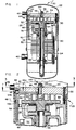
- Figure 1 shows a cross-sectional view of a low-side scroll compressor according to the invention;
- Figure 2 is an enlarged partial cross section of the upper portion of the compressor illustrated in Figure 1 with the compressor in its de-energized state;
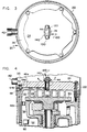
- Figure 3 is a view taken along line 3-3 of Figure 2;
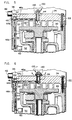
- Figure 4 is a reproduction of Figure 2 showing the disposition of the compressor discharge check valve and gas flow path through the fixed scroll member when the compressor is in normal operation;
- Figure 5 is a reproduction of Figure 2 illustrating the operation of the protective arrangement provided in the compressor and the gas flow therethrough when the compressor is miswired so as to run in the reverse direction or when sub-suction pressures are otherwise caused to develop in the pockets defined by the scroll member;
- Figure 6 is a reproduction of Figure 4 illustrating the operation of the protective arrangement and the gas flow therethrough when abnormally high discharge temperatures occur while the compressor is in operation;
- Figure 7 is a view taken along the line 7-7 in Figure 2;
- Figure 8 is a perspective view of the valve portion of the protective arrangement;
- Figure 9 shows an alternative protective arrangement in a low-side scroll compressor; and
- Figure 10 shows a bimetal valve member of the protective arrangement of Figure 9.
- Referring first to Figures 1, 2 and 3,
compressor 20 has ahermetic shell 22, in which a fixedscroll member 24 is disposed.Fixed scroll member 24 defines adischarge aperture 26 and has aninvolute wrap 28 extending from it. Anorbiting scroll member 30 is likewise disposed inshell 22 and likewise has an extendinginvolute wrap 32 which is disposed in interleaving engagement with theinvolute wrap 28 of fixedscroll member 24. - The operating principles of scroll compressors are well known and described, such as, for instance, in U.S. Patent 4,934,910 which is assigned to the assignee of the present invention and which is incorporated herein by reference. These general operating principles will therefore not be discussed in great detail other than as necessary to describe the present invention.
- Scroll
members discharge aperture 26 whencompressor 20 is in normal operation. The pockets and their movement are created by the relative orbital motion of the scroll members.Discharge pocket 34 is the radially innermost pocket defined by the scroll members and is in flow communication withdischarge aperture 26 of the fixed scroll member. -
Fixed scroll member 24 serves to dividehermetic shell 22 into adischarge pressure portion 36 and asuction pressure portion 38. It should be understood that the division ofhermetic shell 22 into adischarge pressure portion 36 andsuction pressure portion 38 can be accomplished by means other than the use of fixedscroll member 24 such as by the use of an independent barrier or seal member. - A
suction port 40 is provided to permit gas at suction pressure to entersuction pressure portion 38 ofhermetic shell 22. Suction gas enters the radially outermost pocket defined by the scroll members, which is cyclically formed and closed by the orbital movement of the orbiting scroll member with respect to the fixed scroll member. Adischarge port 42 is provided inshell 22 to permit the discharge of compressed gas from thedischarge portion 36 of the compressor. - Communicating between
discharge aperture 26 and thedischarge portion 36 ofshell 22 is adischarge passage 44 through which compressed gas is communicated fromdischarge pocket 34, throughaperture 26 and to shelldischarge portion 36 when the compressor is in normal operation. A protective arrangement for thecompressor 20 comprises means adapted for selectively permitting flow between thesuction pressure portion 38 and thedischarge pocket 34 which flow permitting means comprises apassage 46 in which avalve member 48 is disposed. Thepassage 46 comprisespassage portions chamber 62. -
Compressor 20 is driven by anelectric motor 50 which is disposed in thesuction pressure portion 38 ofshell 22 and is therefore a low-side compressor.Motor 50 includes astator 52 androtor 54. Adrive shaft 56 connectsmotor rotor 54 and orbitingscroll member 28 through aswing link mechanism 58.Motor 50 includes a thermally actuatedline break device 60 associated withstator 52. The line break device is disposed adjacent the opening ofpassage 46 intosuction pressure portion 38 of the compressor shell. - Although
compressor 20 is illustrated as including a swing link mechanism, it should be understood that the present invention is equally applicable to scroll compressors which do not make use of swing link apparatus including scroll compressors of the fixed throw type. It must also be understood that althoughdevice 60 is preferably a thermally actuated line break device which is integral with the compressor motor, other thermally actuated devices are suitable for use and are within the scope of the present invention. -
Compressor 20 includes means, operable when the pressure indischarge pressure portion 36 ofshell 22 exceeds the pressure in discharge pocket 34 (such as upon compressor shutdown), for preventing the backflow of refrigerant gas from discharge pressure portion of the shell back throughpassage 44 and intodischarge pocket 34 between the scroll members. As illustrated, such means are a dischargecheck valve assembly 100 which is disposed atop fixedscroll member 24. - Discharge
check valve assembly 100 is comprised of astop member 120 which is fixedly disposed betweenguide posts 130 as is best illustrated in Figure 3.Valve assembly 100 includes a free-floatingvalve element 140 which operates between a closed position in which it seats over and closespassage 44 fromdischarge portion 36 and an open position in which the flow of discharge gas throughpassage 44 lifts the valve element upward so that it seats againststop member 120. - When
compressor 20 is shut down and pressures withinshell 22 are equalized,valve element 140 rests overdischarge passage 44, as is illustrated in Figure 2, and is maintained there by force of gravity. Whencompressor 22 starts and discharge gas begins to flow throughpassage 44 frompocket 34, the flow of the compressed gaslifts valve element 140 and maintains it in the open position resting againststop member 120 as is illustrated in Figure 4. - Upon compressor shutdown, when orbiting
scroll member 30 ceases to be driven bymotor 50 and the scroll members cease to interact to compress gas between them, gas will immediately begin to flow back out of the discharge pressure portion of the shell, intopassage 44 and through the scroll members in an attempt by the system in which the compressor is employed to equalize its internal pressure. In doing so, the backflowing gas will immediately carryvalve element 140 downward so as to close offpassage 44 fromdischarge portion 36 which prevents any further such backflow. The elevated pressure indischarge portion 36, so long as it exists, will assist in maintainingvalve element 140 seated. Pressure across the valve element and within the compressor will eventually equalize as pressures equalize across the system in which the compressor is employed. - The near immediate closure of the discharge valve assembly prevents the continued rapid backflow of gas from
discharge portion 36 upon compressor shutdown and, more importantly, prevents such continued backflow to the scroll members from the system in whichcompressor 20 is employed. It will be appreciated that the system will contain a relatively much larger volume of discharge pressure gas at such time as the compressor shuts down than will be found in the discharge portion of the compressor shell. If orbitingscroll member 28 were permitted to be driven in the reverse direction by such backflow for too long a period of time, damage to the compressor would result as has been discussed above. - Because
valve element 140 will be in its closed position whenever the compressor is at rest, including those instances where the compressor has not yet been initially wired or has been electrically disconnected, it will be appreciated that ifmotor 50 is initially or subsequently miswired such that orbitingscroll member 28 is driven in a direction opposite from that which is intended, the pockets defined by the scroll member, includingdischarge pocket 34 will be caused to expand and move radially outward. As a result,compressor 20 will function, in effect, as an expander. - In doing so, the scroll members will act against the closed discharge
check valve assembly 100 so that pressure in the compression pockets, includingdischarge pocket 34, is pulled down and becomes less than suction pressure. The pressure may, in fact, approach vacuum becauseclosed valve element 140 prevents the flow of gas from the discharge pressure portion of the compressor and eliminates a souce of gas from which the miswired apparatus can pump. Under such conditions, the tips of the wraps of the scroll members are drawn into exceedingly high frictional contact with the opposing scroll member and severe compressor damage can occur. - As has also been mentioned, the compressor can be damaged by exceedingly high discharge temperatures which can occur, for instance, due to operation of the compressor at pressure ratios outside of its normal operating range. Such temperatures can cause thermal growth of the scroll members, particularly in their wraps, with the result that contact loads on the tips of the scroll members become exceedingly high.
- Referring now to Figures 5 and 6, the operation of the protective arrangement of the
compressor 20 will be discussed in view of the above described abnormal operating conditions. Referring first to Figure 5, operation of the protective arrangement to prevent compressor damage due to the development of sub-suction pressures between the scroll members, such as might occur upon the reverse rotation of the orbiting scroll member, will be considered. - As has previously been indicated, in the event that motor 50 of
compressor 20 is miswired so that it runs backward,compressor 20 will function as an expander. The expansion of the compression pockets, includingdischarge pocket 34, causes a reduction in pressure in those pockets such that pressures less than suction pressure will occur within the pockets in a very short time. - Since
discharge pocket 34 is open to dischargepassage 44 which, under such circumstances, is closed off from the discharge pressure portion of the compressor by the seating ofvalve element 140 overpassage 44, the development of a sub-suction pressure withindischarge pocket 34 will result in the development of sub-suction pressures both indischarge passage 44 and in theportion 46a ofpassage 46.Passage portion 46a is on the discharge pressure side ofvalve member 48 and opens intopassage 44.Valve member 48 is an otherwise free-floating element within thechamber 62 and is unconnected to any other compressor element.Chamber 62 in this embodiment is closed such as byplugs passage 46. - The development of a sub-suction pressure in
passage portion 46a will cause a pressure gradient to occur acrossvalve member 48 since theportion 46b ofpassage 46, which is located on the opposite side ofvalve member 48, is open to the suction pressure portion of the compressor. It will be appreciated that when discharge pressure exists indischarge passage 44, such pressure will be communicated throughpassage portion 46a intochamber 62 and will maintainvalve member 48 seated so as to prevent the flow of gas frompassage portion 46a intopassage portion 46b. However, if the compressor is miswired such that the orbiting scroll member is driven in a reverse direction or if sub-section pressures should otherwise develop in the compression chambers between the scroll members, the suction pressure found inpassage portion 46b will exceed the reduced pressure found inpassage portion 46a. This condition causesvalve member 48 to be lifted by the resulting flow of suction pressure gas throughpassage 46 from the suction pressure portion of the compressor intodischarge passage 44 and intodischarge chamber 34. - Therefore, upon the occurrence of even a slight pressure differential across free-floating
valve member 48, as would be indicative of the development of sub-suction pressure in the discharge pocket defined by the scroll wraps, suction pressure gas will quickly begin to flow throughpassage 46 and intodischarge pocket 34 to prevent the development of excessive contact loads on the scroll wrap tips. At such time as pressure greater than suction pressure comes to exist indischarge pocket 34 anddischarge passage 44, such as by the proper wiring of the compressor and the resulting compression of gas between the scroll members,valve member 48 will be caused to seat withinchamber 62 by discharge pressure gas and will prevent the flow of gas throughpassage 46 under what amounts to a normal operating condition. - Referring now to Figures 4 and 6, during normal compressor operation, as is illustrated in Figure 4, compressed gas at discharge pressure passes out of
discharge chamber 34, throughdischarge passage 44 and effects the lifting ofvalve element 140 of the dischargecheck valve assembly 100. Additionally, that same gas acts onprotective valve member 48 to keep it seated withinchamber 62 overpassage portion 46a thereby preventing the flow of discharge pressure gas throughpassage 46 back to the suction pressure portion of the compressor shell. Under circumstances where the temperature of the compressed gas being discharged fromdischarge chamber 34 becomes abnormally high, however, the exposure ofvalve member 48 withinchamber 62 to such high discharge gas temperatures will causevalve member 48 to become heated. - Referring concurrently now to Figures 6, 7 and 8, it will be appreciated that
valve member 48 is a bimetal valve comprised of twolayers valve member 48 are selected in accordance with their thermal expansion characteristics so that when the valve member is heated the differing expansion rates of the dissimilar metals will cause the valve to deform in the manner of a diaphragm. -
Valve member 48, as is illustrated, has a generally circular portion the facial area of which is greater than the cross sectional area ofpassage portion 46b. The valve member preferably has three legs such that when it deforms, or diaphragms, due to being exposed to gas which is at an abnormally high temperature, the legs of the valve member are maintained in contact with the interior ofchamber 62. The spaces created between the legs of the diaphragmed valve member under such circumstances permit the passage of the abnormally hot discharge pressure gas between them and intopassage portion 46b. The gas then flows intosuction pressure portion 38 of the compressor shell. It will be appreciated that given the direction of gas flow described under these circumstances the flow of gas, along with the force of gravity, will maintain the legs ofvalve member 48 in contact with an interior surface ofchamber 62 as illustrated. -
Passage portion 46b opens intosuction pressure portion 38 ofcompressor shell 22 at a location proximate tomotor stator 52 and the location onmotor stator 52 where thermally actuatedline break device 60 is disposed. Under the circumstances of the development of abnormally high discharge temperatures, the discharge gas will flow throughpassage 46, pastdiaphragmed valve member 48, and will issue into the suction pressure portion of the compressor. The hot discharge gas issuing frompassage portion 46b will cause thermally actuatedline break device 60 to be heated to a point where electrical continuity within the motor will be interrupted and the motor will be de-energized. The thermal characteristics ofvalve member 48 andline break 60 are selected to ensure their operation and the shutdown of the motor before discharge temperatures reach levels which can potentially cause damage to the compressor. - It is to be noted that the protective arrangement of the
compressor 20, as discussed above, eliminates the need to dispose a discharge temperature sensor in the discharge pressure portion of the compressor in close proximity to dischargechamber 34 or to the discharge check valve assembly. It also eliminates the need to penetrateshell 22 or fixedscroll member 24 with sensor wiring. - It is also to be noted, as will be discussed further, that the protective arrangement is equally applicable to compressors which do not have an internal discharge check valve assembly such as where a discharge check valve is disposed downstream of the discharge pressure portion of the compressor shell. If the discharge check valve assembly is located downstream of the discharge pressure portion of the compressor shell it will be appreciated that
protective passage 46, which in net effect is a passage between a discharge pressure and a suction pressure portion of the compressor, can be located anywhere within the compressor so long as it opens both into the discharge and suction pressure portions of the compressor shell. - One such alternative protective arrangement is illustrated in Figure 9. The discharge check valve 100' of this arrangement is schematically illustrated as being disposed in discharge port element 42'. The alternative protective arrangement comprises means adapted for selectively permitting gas flow between the suction pressure portion 38' and the discharge pocket 34' which flow permitting means comprises a passage 46' which is illustrated as an essentially straight passage through the fixed scroll member 24' and includes a chamber 62'. The flow permitting means further comprises a valve member 48' disposed in the chamber 62'. Figure 10 illustrates that protective bimetal valve member 48' is disposed and confined, in a free-floating manner, in a chamber 62'. Chamber 62', in this arrangement, is open directly to the discharge pressure portion 36' of the shell and therethrough to passage 44' and pocket 34'. The valve member 48' is retained in chamber 62' by a retainer insert 66'. The compressor protecting arrangement of Figures 9 and 10 operates on the same principles as the arrangement disclosed in Figures 1-8 including the opening of passage 46' into suction pressure portion 38' adjacent thermally actuated line break device 60'.
- In the above-described embodiments a scroll compressor is provided with a protective arrangement which selectively permits the flow of refrigerant gas (i.) in a first direction within the compressor in response to the development of high compressor discharge temperatures and (ii.) in the opposite direction within the compressor in response to the reverse direction rotation of the driven scroll member but which (iii.) prevents any such flow under normal compressor operating conditions. Such permitted internal refrigerant flow during other than normal operating conditions is through an interruptable passage within the shell of the compressor that communicates between the suction pressure portion of the shell and a portion of the compressor through which discharge gas flows during normal operation.
- The controlled internal refrigerant flow permitted by the protective arrangement prevents compressor damage which would otherwise result from the development of high discharge temperatures or the development of sub-suction pressures between the scroll members such as can result from reverse direction compressor motor rotation. When the circumstances of high discharge temperature or sub-suction pressures between the scroll members do not exist, refrigerant flow through the internal passage is prevented.
- In the embodiments, the protective valve member is disposed in the passage which is arranged to communicate between the suction portion of the compressor shell and a location downstream of the aperture through which compressed gas is discharged from between the scroll members in normal operation. The valve member is, however, located upstream of the discharge check valve which operates to cut off the backflow of compressed gas through the compressor upon normal compressor shutdown.
- The protective valve member is preferably a free-floating bimetal valve which, as described above, is unconnected to any other compressor element, and is disposed in an enlarged portion of the internal refrigerant passage. In use, the protective valve member is lifted by the flow of gas from the suction pressure portion of the compressor through the passage which occurs when a pressure gradient develops across the valve member. Such a pressure gradient across the valve member will develop under circumstances which include the reverse direction rotation of the driven scroll member and the operation of the compressor as an expander as explained above.
- Such protective refrigerant flow through the passage will be from the suction portion of the compressor shell, through the passage in which the bimetal valve is disposed and back to a pocket defined by the scroll members. This will result in general pressure equalization between the pockets defined by the scroll members and the suction pressure portion of the compressor. The compressor, acting as an expander, will pump from suction back to suction so long as the improper reverse direction motor rotation continues. In net effect, the compression apparatus is short-circuited under such circumstances by the lifting of the protective valve member in a manner which prevents damage to the scroll members.
- Upon the occurrence of abnormally high discharge temperatures, the bimetal valve, which is normally exposed to compressor discharge gas through the passage in which it is disposed, deforms in the manner of a diaphragm which permits the venting of discharge gas around it and through the passage back to the suction pressure portion. By positioning the passage, where it opens into the suction pressure portion of the compressor, to be near a thermally actuated motor protection device, the motor protection device can be quickly actuated to shut the compressor down under high discharge temperature condition. The compressor is therefore protected from high discharge temperatures in a manner which does not require the use of a temperature sensor disposed in the discharge portion of the shell or the routing of sensor leads out of that portion of the compressor.
- As will be appreciated, there are other alternative arrangements and equivalents which are suggested by and fall within the scope of the invention described herein. Therefore, the present invention is not to be limited other than in accordance with the language of the claims which follow.
Claims (19)
- Apparatus for compressing a gas comprising:a shell (22) defining a suction pressure portion (38;38') and a discharge pressure portion (36;36');a first scroll member (24;24') disposed in said shell, said first scroll member having an involute wrap (28) and defining a discharge aperture (26) in flow communication with said discharge pressure portion of the shell;a second scroll member (30) disposed in said shell, said second scroll member having an involute wrap (32), the involute wraps of said first and said second scroll members being in interleaving engagement and cooperating to define a plurality of pockets including a discharge pocket (34;34') in flow communication with said discharge aperture (26); andmeans (46a,46b,48,62;46',48',62') for permitting gas flow from said suction pressure portion (38;38') to said discharge pocket (34;34') when, in use of the apparatus, gas pressure in said discharge pocket is less than gas pressure in said suction pressure portion, characterised in that said flow permitting means (46a,46b,48,62;46',48',62') is adapted for selectively permitting (i) said gas flow from the suction pressure portion (38;38') to said discharge pocket (34;34') when, in use of the apparatus, gas pressure in said discharge pocket is less than gas pressure in said suction pressure portion and (ii) gas flow from said discharge pocket to said suction pressure portion when during said use, discharge gas temperature exceeds a predetermined temperature.
- Apparatus according to claim 1, wherein said flow permitting means includes means (46a,46b,62;46',62') defining a passage internal of said shell which communicates between said suction pressure portion and said discharge pocket.
- Apparatus according to claim 2, wherein said flow permitting means includes a valve member (48;48'), said valve member being actuated to permit said gas flow through said passage (i) by the development of gas pressure in said discharge pocket (34;34') less than gas pressure in said suction pressure portion (38;38') and (ii) by the occurrence of discharge gas temperatures which exceed said predetermined temperature.
- Apparatus according to claim 3, wherein said valve member (48;48') is a thermally responsive bimetal valve member.
- Apparatus according to claim 4, wherein said valve member (48;48') is disposed entirely within said passage and is not connected to any other element of the apparatus.
- Apparatus according to claim 5, wherein said bimetal valve member responds to discharge temperatures which exceed said predetermined temperature by changing shape to permit said gas flow from said discharge pocket to said suction pressure portion.
- Apparatus according to any one of claims 2 to 6, further comprising means (100;100') for preventing backflow of gas from said discharge pressure portion (36;36') of the shell to said discharge pocket (34;34') when the pressure in said discharge pocket is less than the pressure in said discharge pressure portion (38;38').
- Apparatus according to claim 7, wherein said passage (46a,46b,62;46',62') has one end disposed within said shell (22) at a location upstream of said backflow preventing means (100;100').
- Apparatus according to claim 8, wherein said passage communicates with said discharge pocket (34) via an opening (44) upstream of said backflow preventing means (100).
- Apparatus according to claim 7, 8 or 9, wherein said backflow preventing means (100') is disposed downstream of said discharge pressure portion (36') of the shell.
- Apparatus according to any one of claims 2 to 10, wherein said passage (46a,46b,62;46',62') is at least partially defined by a fixed one (24;24') of said scroll members.
- Apparatus according to any one of the preceding claims, further comprising a motor (50) for driving one of said first and second scroll members (24,30;24'), said motor being disposed in said suction pressure portion of the shell (22).
- Apparatus according to claim 12 when dependent on claim 2, wherein said passage (46a,46b,62;46',62') opens into said suction pressure portion of the shell adjacent a thermally actuated protective device (60;60') for de-energising said motor when exposed to temperatures exceeding said predetermined temperature.
- Apparatus according to claim 13, wherein said thermally actuated protective device (60;60') is a line break which is integral to said motor (50).
- A method for protecting a scroll compressor against damage due to reverse direction motor rotation or high discharge temperatures, the method comprising the steps of defining a passage in said compressor, said passage communicating between a suction pressure portion of said compressor and a portion of said compressor through which discharge gas flows when said compressor is in normal operation, and controlling flow through said passage such that: (i) gas is permitted to flow through said passage from said suction pressure portion to said portion of said compressor through which discharge gas normally flows when the pressure in said suction pressure portion exceeds the pressure in said portion of said compressor through which discharge gas normally flows; (ii) gas is permitted to flow through said passage from said portion of said compressor through which discharge gas normally flows to said suction pressure portion of said compressor when the temperature of said gas exceeds a predetermined temperature; and (iii) gas is prevented from flowing through said passage when said discharge temperature is less than said predetermined temperature and when the pressure in said portion of said compressor through which discharge gas normally flows exceeds the pressure in said suction pressure portion.
- A method according to claim 15, further comprising the step of disposing a thermally responsive valve in said passage.
- A method according to claim 15 or 16, wherein said scroll compressor includes a motor disposed in said suction pressure portion of said shell, the method further comprising the step of disposing a thermally actuated motor protective device adjacent the location where said passage opens into said suction pressure portion of said shell.
- A method according to claim 16 or 17, further comprising the step of fabricating said valve from a bimetal so that said valve responds to temperatures in excess of said predetermined temperature by changing shape, the change of shape of said valve opening said passage to gas flow when discharge gas temperatures exceed said predetermined temperature.
- The method according to claim 18, wherein said fabricating step includes the step of sizing said valve such that when disposed in said passage the valve is free to move within a predetermined portion of said passage and is not connected to said compressor.
Applications Claiming Priority (3)
| Application Number | Priority Date | Filing Date | Title |
|---|---|---|---|
| US07/811,777 US5186613A (en) | 1991-12-20 | 1991-12-20 | Reverse phase and high discharge temperature protection in a scroll compressor |
| US811777 | 1991-12-20 | ||
| PCT/US1992/009797 WO1993013317A1 (en) | 1991-12-20 | 1992-11-13 | Reverse phase and high discharge temperature protection in a scroll compressor |
Publications (2)
| Publication Number | Publication Date |
|---|---|
| EP0617759A1 EP0617759A1 (en) | 1994-10-05 |
| EP0617759B1 true EP0617759B1 (en) | 1996-03-27 |
Family
ID=25207543
Family Applications (1)
| Application Number | Title | Priority Date | Filing Date |
|---|---|---|---|
| EP92925204A Expired - Lifetime EP0617759B1 (en) | 1991-12-20 | 1992-11-13 | Reverse phase and high discharge temperature protection in a scroll compressor |
Country Status (8)
| Country | Link |
|---|---|
| US (1) | US5186613A (en) |
| EP (1) | EP0617759B1 (en) |
| JP (1) | JPH07502583A (en) |
| AU (1) | AU3135393A (en) |
| CA (1) | CA2123325C (en) |
| HK (1) | HK210896A (en) |
| TW (1) | TW235331B (en) |
| WO (1) | WO1993013317A1 (en) |
Families Citing this family (24)
| Publication number | Priority date | Publication date | Assignee | Title |
|---|---|---|---|---|
| US5849261A (en) * | 1991-02-08 | 1998-12-15 | Diatide, Inc. | Radiolabeled vasoactive intestinal peptides for diagnosis and therapy |
| US5248244A (en) * | 1992-12-21 | 1993-09-28 | Carrier Corporation | Scroll compressor with a thermally responsive bypass valve |
| US5290154A (en) * | 1992-12-23 | 1994-03-01 | American Standard Inc. | Scroll compressor reverse phase and high discharge temperature protection |
| US5368446A (en) * | 1993-01-22 | 1994-11-29 | Copeland Corporation | Scroll compressor having high temperature control |
| US5803716A (en) * | 1993-11-29 | 1998-09-08 | Copeland Corporation | Scroll machine with reverse rotation protection |
| US5591014A (en) * | 1993-11-29 | 1997-01-07 | Copeland Corporation | Scroll machine with reverse rotation protection |
| US5366352A (en) * | 1993-12-13 | 1994-11-22 | Deblois Raymond L | Thermostatic compressor suction inlet duct valve |
| US5452989A (en) * | 1994-04-15 | 1995-09-26 | American Standard Inc. | Reverse phase and high discharge temperature protection in a scroll compressor |
| US5707210A (en) * | 1995-10-13 | 1998-01-13 | Copeland Corporation | Scroll machine with overheating protection |
| FR2756877B1 (en) * | 1996-12-05 | 1999-01-22 | Maneurop | HERMETIC COMPRESSOR FOR GAS CIRCULATION |
| US5807081A (en) * | 1997-01-06 | 1998-09-15 | Carrier Corporation | Combination valve for screw compressors |
| US6171064B1 (en) * | 1998-03-23 | 2001-01-09 | Scroll Technologies | Reverse rotation detection for scroll compressor utilizing suction temperature |
| US20050171486A1 (en) * | 1999-05-10 | 2005-08-04 | Hochman Mark N. | Safety syringe |
| US6267565B1 (en) | 1999-08-25 | 2001-07-31 | Copeland Corporation | Scroll temperature protection |
| ITMO20010176A1 (en) * | 2001-08-31 | 2003-03-03 | Esam Spa | ADJUSTMENT DEVICE FOR COMPRESSORS - ASPIRATORS |
| US6821092B1 (en) | 2003-07-15 | 2004-11-23 | Copeland Corporation | Capacity modulated scroll compressor |
| KR100585799B1 (en) * | 2003-12-19 | 2006-06-07 | 엘지전자 주식회사 | High temperature prevention device of scroll compressor |
| KR100585798B1 (en) * | 2003-12-19 | 2006-06-07 | 엘지전자 주식회사 | Overheat prevention device of scroll compressor |
| US20070036661A1 (en) * | 2005-08-12 | 2007-02-15 | Copeland Corporation | Capacity modulated scroll compressor |
| JP5278496B2 (en) * | 2011-03-25 | 2013-09-04 | 株式会社豊田自動織機 | Vehicle exhaust heat recovery system |
| US10487832B2 (en) * | 2016-12-22 | 2019-11-26 | Lennox Industries Inc. | Method and apparatus for pressure equalization in rotary compressors |
| US10801510B2 (en) | 2017-04-24 | 2020-10-13 | Lennox Industries Inc. | Method and apparatus for pressure equalization in rotary compressors |
| CN112219076A (en) | 2018-04-09 | 2021-01-12 | 开利公司 | Prevent reverse rotation in centrifugal compressors |
| KR20240109318A (en) * | 2023-01-03 | 2024-07-11 | 삼성전자주식회사 | Scroll compressor with overheating protection apparatus |
Family Cites Families (10)
| Publication number | Priority date | Publication date | Assignee | Title |
|---|---|---|---|---|
| US4934910A (en) * | 1980-10-08 | 1990-06-19 | American Standard, Inc. | Scroll-type fluid apparatus with radially compliant driving means |
| JPS60101296A (en) * | 1983-10-21 | 1985-06-05 | Hitachi Ltd | Scroll fluid machine |
| JPS61218792A (en) * | 1985-03-25 | 1986-09-29 | Matsushita Electric Ind Co Ltd | Scroll compressor |
| US4828462A (en) * | 1987-12-10 | 1989-05-09 | Dana Corporation | Pressure detecting system for a hydraulic device |
| US4820130A (en) * | 1987-12-14 | 1989-04-11 | American Standard Inc. | Temperature sensitive solenoid valve in a scroll compressor |
| US4840545A (en) * | 1988-05-16 | 1989-06-20 | American Standard Inc. | Scroll compressor relief valve |
| JPH0221696A (en) * | 1988-07-11 | 1990-01-24 | Hitachi Ltd | Multilayer circuit board |
| US4955795A (en) * | 1988-12-21 | 1990-09-11 | Copeland Corporation | Scroll apparatus control |
| JP2567712B2 (en) * | 1989-12-28 | 1996-12-25 | 三洋電機株式会社 | Scroll compressor |
| US5141407A (en) * | 1990-10-01 | 1992-08-25 | Copeland Corporation | Scroll machine with overheating protection |
-
1991
- 1991-12-20 US US07/811,777 patent/US5186613A/en not_active Expired - Fee Related
-
1992
- 1992-11-13 JP JP5511642A patent/JPH07502583A/en active Pending
- 1992-11-13 EP EP92925204A patent/EP0617759B1/en not_active Expired - Lifetime
- 1992-11-13 WO PCT/US1992/009797 patent/WO1993013317A1/en not_active Ceased
- 1992-11-13 AU AU31353/93A patent/AU3135393A/en not_active Abandoned
- 1992-11-13 CA CA002123325A patent/CA2123325C/en not_active Expired - Fee Related
- 1992-11-17 TW TW081109193A patent/TW235331B/zh active
-
1996
- 1996-11-28 HK HK210896A patent/HK210896A/en not_active IP Right Cessation
Also Published As
| Publication number | Publication date |
|---|---|
| AU3135393A (en) | 1993-07-28 |
| CA2123325C (en) | 1997-11-04 |
| HK210896A (en) | 1996-12-06 |
| TW235331B (en) | 1994-12-01 |
| US5186613A (en) | 1993-02-16 |
| CA2123325A1 (en) | 1993-07-08 |
| WO1993013317A1 (en) | 1993-07-08 |
| JPH07502583A (en) | 1995-03-16 |
| EP0617759A1 (en) | 1994-10-05 |
Similar Documents
| Publication | Publication Date | Title |
|---|---|---|
| US5186613A (en) | Reverse phase and high discharge temperature protection in a scroll compressor | |
| US5290154A (en) | Scroll compressor reverse phase and high discharge temperature protection | |
| US5452989A (en) | Reverse phase and high discharge temperature protection in a scroll compressor | |
| EP1286052B1 (en) | Scroll compressor | |
| US4840545A (en) | Scroll compressor relief valve | |
| JP3796277B2 (en) | Scroll machine | |
| US5591014A (en) | Scroll machine with reverse rotation protection | |
| US6210120B1 (en) | Low charge protection vent | |
| US5803716A (en) | Scroll machine with reverse rotation protection | |
| US6077057A (en) | Scroll compressor with back pressure seal protection during reverse rotation | |
| KR19980042643A (en) | Reverse rotation protected scroll machine | |
| US6190138B1 (en) | Flow valve for correcting reverse rotation in scroll compressor | |
| JP3766725B2 (en) | Oil-cooled screw compressor | |
| US7547195B2 (en) | Scroll compressor with high side to low side oil bleed valve | |
| US6217302B1 (en) | Floating seal bias for reverse fun protection in scroll compressor | |
| US5201648A (en) | Screw compressor mechanical oil shutoff arrangement | |
| JP4109246B2 (en) | Scroll compressor with overheat prevention device | |
| US20030072663A1 (en) | Scroll compressor with condition responsive back pressure chamber valve | |
| JP2005180448A (en) | Overheating prevention device of scroll compressor | |
| EP0535533B1 (en) | Screw vacuum pump | |
| KR100308289B1 (en) | Protection device of a scroll compressor | |
| US6485268B1 (en) | Oil utilized as motor protector trip for scroll compressor | |
| US6379133B1 (en) | Scroll compressor with reduced stiction surface for check valve | |
| US6491500B1 (en) | Scroll compressor with motor protector in non-orbiting scroll and flow enhancement | |
| US6152700A (en) | Hermetic compressor with remote temperature sensing means |
Legal Events
| Date | Code | Title | Description |
|---|---|---|---|
| PUAI | Public reference made under article 153(3) epc to a published international application that has entered the european phase |
Free format text: ORIGINAL CODE: 0009012 |
|
| 17P | Request for examination filed |
Effective date: 19940714 |
|
| AK | Designated contracting states |
Kind code of ref document: A1 Designated state(s): FR GB |
|
| 17Q | First examination report despatched |
Effective date: 19950217 |
|
| GRAH | Despatch of communication of intention to grant a patent |
Free format text: ORIGINAL CODE: EPIDOS IGRA |
|
| GRAA | (expected) grant |
Free format text: ORIGINAL CODE: 0009210 |
|
| AK | Designated contracting states |
Kind code of ref document: B1 Designated state(s): FR GB |
|
| ET | Fr: translation filed | ||
| PLBE | No opposition filed within time limit |
Free format text: ORIGINAL CODE: 0009261 |
|
| STAA | Information on the status of an ep patent application or granted ep patent |
Free format text: STATUS: NO OPPOSITION FILED WITHIN TIME LIMIT |
|
| 26N | No opposition filed | ||
| PGFP | Annual fee paid to national office [announced via postgrant information from national office to epo] |
Ref country code: GB Payment date: 19971104 Year of fee payment: 6 |
|
| PGFP | Annual fee paid to national office [announced via postgrant information from national office to epo] |
Ref country code: FR Payment date: 19971112 Year of fee payment: 6 |
|
| PG25 | Lapsed in a contracting state [announced via postgrant information from national office to epo] |
Ref country code: GB Free format text: LAPSE BECAUSE OF NON-PAYMENT OF DUE FEES Effective date: 19981113 |
|
| GBPC | Gb: european patent ceased through non-payment of renewal fee |
Effective date: 19981113 |
|
| PG25 | Lapsed in a contracting state [announced via postgrant information from national office to epo] |
Ref country code: FR Free format text: LAPSE BECAUSE OF NON-PAYMENT OF DUE FEES Effective date: 19990730 |
|
| REG | Reference to a national code |
Ref country code: FR Ref legal event code: ST |