EP0617649B1 - Deep-boring drill - Google Patents
Deep-boring drill Download PDFInfo
- Publication number
- EP0617649B1 EP0617649B1 EP93915624A EP93915624A EP0617649B1 EP 0617649 B1 EP0617649 B1 EP 0617649B1 EP 93915624 A EP93915624 A EP 93915624A EP 93915624 A EP93915624 A EP 93915624A EP 0617649 B1 EP0617649 B1 EP 0617649B1
- Authority
- EP
- European Patent Office
- Prior art keywords
- deep hole
- drill
- drilling
- cutting
- hollow
- Prior art date
- Legal status (The legal status is an assumption and is not a legal conclusion. Google has not performed a legal analysis and makes no representation as to the accuracy of the status listed.)
- Expired - Lifetime
Links
Images

Classifications
-
- B—PERFORMING OPERATIONS; TRANSPORTING
- B23—MACHINE TOOLS; METAL-WORKING NOT OTHERWISE PROVIDED FOR
- B23Q—DETAILS, COMPONENTS, OR ACCESSORIES FOR MACHINE TOOLS, e.g. ARRANGEMENTS FOR COPYING OR CONTROLLING; MACHINE TOOLS IN GENERAL CHARACTERISED BY THE CONSTRUCTION OF PARTICULAR DETAILS OR COMPONENTS; COMBINATIONS OR ASSOCIATIONS OF METAL-WORKING MACHINES, NOT DIRECTED TO A PARTICULAR RESULT
- B23Q5/00—Driving or feeding mechanisms; Control arrangements therefor
- B23Q5/02—Driving main working members
- B23Q5/04—Driving main working members rotary shafts, e.g. working-spindles
-
- B—PERFORMING OPERATIONS; TRANSPORTING
- B23—MACHINE TOOLS; METAL-WORKING NOT OTHERWISE PROVIDED FOR
- B23B—TURNING; BORING
- B23B51/00—Tools for drilling machines
- B23B51/04—Drills for trepanning
- B23B51/042—Drills for trepanning with lubricating or cooling equipment
-
- Y—GENERAL TAGGING OF NEW TECHNOLOGICAL DEVELOPMENTS; GENERAL TAGGING OF CROSS-SECTIONAL TECHNOLOGIES SPANNING OVER SEVERAL SECTIONS OF THE IPC; TECHNICAL SUBJECTS COVERED BY FORMER USPC CROSS-REFERENCE ART COLLECTIONS [XRACs] AND DIGESTS
- Y10—TECHNICAL SUBJECTS COVERED BY FORMER USPC
- Y10S—TECHNICAL SUBJECTS COVERED BY FORMER USPC CROSS-REFERENCE ART COLLECTIONS [XRACs] AND DIGESTS
- Y10S408/00—Cutting by use of rotating axially moving tool
- Y10S408/705—Drilling deep holes
-
- Y—GENERAL TAGGING OF NEW TECHNOLOGICAL DEVELOPMENTS; GENERAL TAGGING OF CROSS-SECTIONAL TECHNOLOGIES SPANNING OVER SEVERAL SECTIONS OF THE IPC; TECHNICAL SUBJECTS COVERED BY FORMER USPC CROSS-REFERENCE ART COLLECTIONS [XRACs] AND DIGESTS
- Y10—TECHNICAL SUBJECTS COVERED BY FORMER USPC
- Y10T—TECHNICAL SUBJECTS COVERED BY FORMER US CLASSIFICATION
- Y10T408/00—Cutting by use of rotating axially moving tool
- Y10T408/03—Processes
-
- Y—GENERAL TAGGING OF NEW TECHNOLOGICAL DEVELOPMENTS; GENERAL TAGGING OF CROSS-SECTIONAL TECHNOLOGIES SPANNING OVER SEVERAL SECTIONS OF THE IPC; TECHNICAL SUBJECTS COVERED BY FORMER USPC CROSS-REFERENCE ART COLLECTIONS [XRACs] AND DIGESTS
- Y10—TECHNICAL SUBJECTS COVERED BY FORMER USPC
- Y10T—TECHNICAL SUBJECTS COVERED BY FORMER US CLASSIFICATION
- Y10T408/00—Cutting by use of rotating axially moving tool
- Y10T408/44—Cutting by use of rotating axially moving tool with means to apply transient, fluent medium to work or product
-
- Y—GENERAL TAGGING OF NEW TECHNOLOGICAL DEVELOPMENTS; GENERAL TAGGING OF CROSS-SECTIONAL TECHNOLOGIES SPANNING OVER SEVERAL SECTIONS OF THE IPC; TECHNICAL SUBJECTS COVERED BY FORMER USPC CROSS-REFERENCE ART COLLECTIONS [XRACs] AND DIGESTS
- Y10—TECHNICAL SUBJECTS COVERED BY FORMER USPC
- Y10T—TECHNICAL SUBJECTS COVERED BY FORMER US CLASSIFICATION
- Y10T408/00—Cutting by use of rotating axially moving tool
- Y10T408/50—Cutting by use of rotating axially moving tool with product handling or receiving means
-
- Y—GENERAL TAGGING OF NEW TECHNOLOGICAL DEVELOPMENTS; GENERAL TAGGING OF CROSS-SECTIONAL TECHNOLOGIES SPANNING OVER SEVERAL SECTIONS OF THE IPC; TECHNICAL SUBJECTS COVERED BY FORMER USPC CROSS-REFERENCE ART COLLECTIONS [XRACs] AND DIGESTS
- Y10—TECHNICAL SUBJECTS COVERED BY FORMER USPC
- Y10T—TECHNICAL SUBJECTS COVERED BY FORMER US CLASSIFICATION
- Y10T408/00—Cutting by use of rotating axially moving tool
- Y10T408/89—Tool or Tool with support
- Y10T408/895—Having axial, core-receiving central portion
Definitions
- the present invention relates to a method for producing deep boreholes, in particular in wood and similarly structured materials, as well as a deep hole drill suitable for this purpose and a deep hole drilling machine used to carry out the method. with such a deep hole drill.
- the task at times is to drill deep holes in a workpiece. It is particularly important to ensure that the drill does not run in the borehole and therefore does not lose the desired direction.
- the risk of the drill running out is greatly increased by the structure formed by the tree rings.
- intermittent retrieval is used, the drill being automatically returned from the borehole at constant intervals and thus carrying the chips out with it.
- Conventional twist drills are used as drills. This method has several disadvantages. First of all, it requires complex control in order to optimize the feed and retraction movement in time and to prevent the drill from reaching the end of the bore at too high a speed. Secondly, the drilling process is interrupted several times, which on the one hand results in a loss of time and on the other hand affects the uniformity of the drilling. Thirdly, not all of the material removed is removed. The deeper the borehole, the greater the remaining stock of chips that remain in the borehole, which can block the drill.
- a deep hole drill is known, the cutting elements of which are located on a pipe.
- a second pipe is located centrally in the first and is connected to it in a rotationally fixed manner. It serves to supply a coolant, which then flows back through the annular cavity between the two pipes from the drilling site. At the same time, it removes the chips generated during drilling.
- the construction of this drill is only of limited suitability for woodworking. If large chips are broken off, they can clog the annular cavity and block the removal of the chips. This is further enhanced by the fact that the two concentric tubes are stationary relative to each other.
- a hole saw device which consists of a guide drill and a hole saw.
- the guide drill is a twist drill on which the hole saw is held in a rotationally fixed manner as a crown drill.
- the guide drill is in front of the hole saw. This device is not suitable for woodworking. If the pilot drill runs along a tree ring, this can cause the drill to run.
- This object is achieved by a method for producing deep boreholes with the features of patent claim 1.
- the deep hole drilling machine for drilling deep holes essentially consists, as can be seen in FIG. 1, of a drilling device A, a feed device B and a frame, which is not shown here.
- the devices A, B are fixed on the frame.
- the drilling device A performs the rotary movement of the drill and ensures that the chips are guided away by means of a compressed air supply, not shown.
- the feed device B generates the feed of the drilling device A and determines the depth of the bore.
- a feed motor 5 drives a transmission in the form of a closed chain 6 via a gear.
- a carrier element 4, which carries the drilling device A, is fastened to this chain 6.
- the desired feed of the drilling device A can be achieved.
- the borehole depth can also be set electronically or mechanically.
- the feed device B can be assembled from commercially available parts, and its structure can be chosen as desired. It can also be operated using compressed air.
- the drilling device A consists of a drive motor 1 and a deep hole drill 2.
- the drive motor 1 has a hollow shaft. It drives the deep hole drill 2.
- the deep hole drill 2 is composed of two concentrically arranged, long, one-part or multi-part hollow shanks, which form the drilling elements.
- the outer diameter of the inner hollow shaft 22 corresponds to the inner diameter of the outer hollow shaft 21, as can be seen in FIG. 3.
- the outer hollow shaft 21 is fastened to the drive motor 1 with the usual fastening means and protrudes on its side facing the workpiece, hereinafter referred to as the drill side, by at least the length of the desired bore.
- the inner hollow shaft 22 passes through the hollow shaft of the drive motor 1, that is, it protrudes on both sides thereof, the drill side and the rear.
- the two hollow shafts 21, 22 are operated with different ratios: the outer hollow shaft 21 with a large ratio 11, the inner hollow shaft 22 with a small ratio 12.
- the inner hollow shaft 22 therefore has a higher speed than the outer hollow shaft 21. It differentiates generally by a factor of 90 on the speed of the outer hollow shaft.
- the deep hole drill 2 is slidably mounted in a guide element 3 near the workpiece W. This can, for example, be attached to the frame of the drilling machine, not shown here.
- the guide element 3 ensures the stability of the deep hole drill 2 especially at the beginning of the drilling and guides it during the entire machining time.
- the outer hollow shaft 21 has, in the vicinity of the drive motor 1 on the drill side in a defined area, openings 21 ′′ evenly distributed over its circumference, as can be seen in FIG.
- a compressed air unit 23 is located above this area.
- the inner hollow shank 22 has longitudinal grooves 222 distributed symmetrically on its circumference, which extend from the same area to the end of the hollow shank on the drill side. These longitudinal grooves 222 are created by grinding the jacket of the inner hollow shaft 22. In the area thus created between the two hollow shafts there are symmetrically distributed feed channels 24, as shown in FIG. 4.
- the drill ends of both hollow shanks are provided with cutting elements.
- the outer hollow shaft has a drill bit 21 '
- the inner hollow shaft has a core drill 22'.
- the core drill 22 'of the inner hollow shaft 22 is set back or aligned with the drill bit 21' of the outer hollow shaft 21. In no case does it protrude from the drill bit 21 '. It is thereby achieved that the inner drilling element runs after the outer drilling element.
- the outer and the inner hollow shaft are both preferably made in several parts.
- the drill bit 21 'and the core drill 22' are formed on individual, short hollow cylinders which are placed on the long parts of the hollow shafts 21, 22.
- the actual cutting edges, preferably made of hard metal, are welded or soldered onto these drill heads formed in this way. In the case of the core bit, this hard metal cutting edge is a toothed ring, in the case of the core bit it is a special cutting plate. The cutting edges can be reground without having to dismantle the entire hollow shank.
- the drill bit 21 In the operating state, the drill bit 21 'drills a pin from the workpiece. It guides the deep hole drill 2 and its shape prevents it from running.
- a preferred embodiment of the core drill 22 ' is described below.
- a special core drill 22 ' is used so that the deep hole drill does not run even in woods with strongly pronounced annual rings or in areas with knots. If you choose a core drill shaped to a point, there is a risk that it will trap distinctive tree rings in the wood and the deep hole drill will run despite the guidance of the drill bit.
- the core drill 22 'according to the invention therefore has no tip, but a cutting edge arranged perpendicular to the longitudinal direction. It is shown in Figures 5, 6 and 7.
- the core drill 22 ' consists of a short hollow cylinder forming the drill head, which has an internal thread at one end. So that it can be screwed onto the corresponding external thread of the inner hollow shaft 22.
- the cutting elements At the other end are the cutting elements, the cutting edges of which are shown in the figures with thin lines.
- As a child Cutting elements serve two peripheral shoulder parts 223, which are arranged diametrically to one another and run into cutting edges with respect to the jacket 221 of the hollow cylinder. Rotated 90 ° to the connecting diagonal of the shoulder parts 223, a cutting edge 224 in the form of a plate diagonally bridges the hollow cylinder.
- the cutting edge 224 projects beyond the peripheral shoulder parts 223 and serves as an essential machining element.
- main cutting edges 224 ' which are arranged centrosymmetrically about the drill axis and whose cutting edges are parallel to the diagonal.
- the cutting edge of the one main cutting edge 224 'thus lies on one side of the diagonal, the cutting edge of the other main cutting edge on the other side.
- Both main cutting edges 224 ' have the same but opposite angle of inclination with respect to the drill axis. Since the cutting edges are approximately perpendicular to the drill axis, the main cutting edges 224 'work like a face milling machine. In the area of the drill axis, the main cutting edges 224 'merge into a secondary cutting edge 224''along their inclination. These are also centrosymmetrical to the drill axis and form an acute angle with the cutting edges in the incline plane.
- the two lugs of the cutting edge 224 on the hollow cylinder are tapered in relation to the upper area of the cutting edge 224.
- the hollow cylinder has four longitudinal grooves 222 'distributed symmetrically on the outer surface, which extend over the entire length of the hollow cylinder.
- the other two longitudinal grooves 222' are offset by 90 ° and extend into the area of the shoulder of the cutting edge. In this area, the two longitudinal grooves 222 'branch out in a V-shape and each end on one side of the shoulder.
- the longitudinal grooves 222 'used for the air supply must be aligned with those of the multi-part extension parts of the hollow shaft 22 which adjoin the drill head.
- Compressed air is supplied from the outside through the compressed air supply unit 23. It flows through the feed channels 24 between the two hollow shafts 21, 22 into the drill-side end of the deep hole drill 2 into the bore. It cools both hollow shafts with the integrated or attached cutting elements.
- the inner hollow shaft 22 is supported by the air cushion.
- the core of the inner hollow shaft 22 serves as the discharge channel 25. The air escapes through this discharge channel 25 and at the same time, as the cooling and transport medium, leads the removed material of the workpiece away from the drilling point.
- the chips are blown out of the inner hollow shaft 21 on the back of the drive motor.
- the special shape of the core drill 22 'optimizes the air distribution at the drilling point.
- the longitudinal grooves 222 'on the peripheral shoulder parts 223 guide the air into the vicinity of the drill bit 21' of the outer hollow shaft 21 so that the material removed there is captured. Detect the branched longitudinal grooves 222 'at the tips of the cutting edge 224 especially the chips generated by the cutting edge 224 and the peripheral shoulder parts 223.
- the process used by this drill with deep hole drill ensures the flow when the chips are removed.
- the chips are comminuted by the core drill 22 ′ to dimensions that are much smaller than the diameter of the discharge channel 25.
- a clumping of the fine chips or sawdust is prevented by the fact that the rapid rotation and the arrangement of the longitudinal grooves 222 'of the core drill 22' generate air vortices on which the chips are carried as individual parts.
Abstract
Description
Die vorliegende Erfindung betrifft ein Verfahren zur Herstellung von tiefen Bohrlöchern, insbesondere in Holz und gleichartig strukturierten Materialien sowie einen hierzu geeigneten Tieflochbohrer und eine zur Durchführung des Verfahrens dienende Tieflochbohrmaschine. mit einem solchen Tieflochbohrer.The present invention relates to a method for producing deep boreholes, in particular in wood and similarly structured materials, as well as a deep hole drill suitable for this purpose and a deep hole drilling machine used to carry out the method. with such a deep hole drill.
Bei der Materialbearbeitung stellt sich zeitweise die Aufgabe, tiefe Löcher in ein Werkstück zu bohren. Dabei ist besonders darauf zu achten, dass der Bohrer im Bohrloch nicht verläuft und dadurch nicht die gewünschte Richtung verliert. Bei der Bearbeitung von Holz ist die Gefahr des Verlaufens des Bohrers durch die durch die Jahrringe gebildete Struktur stark erhöht.
Ebenso muss dem Abtransport der Späne grosse Beachtung geschenkt werden. Diese können insbesondere bei einem langen Förderweg den Bohrer blockieren und zum Bruch desselben führen. Auch dies ist besonders in der Holzbearbeitung der Fall, da hier oft grossstückig brechende Späne auftreten.When processing materials, the task at times is to drill deep holes in a workpiece. It is particularly important to ensure that the drill does not run in the borehole and therefore does not lose the desired direction. When working with wood, the risk of the drill running out is greatly increased by the structure formed by the tree rings.
Great attention must also be paid to the removal of the chips. These can block the drill bit and cause it to break, particularly if the conveying path is long. This is also particularly the case in woodworking, as there are often large chips that break.
In der Holzbearbeitung wird meist das Bohren von tiefen Löchern dadurch umgangen, dass entweder ein Werkstück geschlitzt wird oder eine Nut gefräst wird und die offene Oberfläche anschliessend wieder verschlossen wird. Diese Naht ist zum Teil unerwünscht, vorallem wenn sie sich in einer Sichtebene befindet.In woodworking, drilling of deep holes is usually avoided by either slitting a workpiece or milling a groove and then closing the open surface again. This seam is sometimes undesirable, especially if it is in a view plane.
In der Technik sind verschiedene Tieflochbohrer und damit verbundene Verfahren bekannt, die das Problem des Verlaufens des Bohrers oder der Spanabführung auf unterschiedliche Art lösen. Diese Tieflochbohrer werden jedoch hauptsächlich für Metall- oder Keramikbearbeitung eingesetzt.Various deep hole drills and associated methods are known in the art which solve the problem of the drill running or chip removal in different ways. However, these deep hole drills are mainly used for metal or ceramic processing.
Bei einer Ausführungsform, die in CH-A-653 270 dargelegt wird, wird mit intermittierender Rückholung gearbeitet, wobei der Bohrer in konstanten Zeitabständen automatisch aus dem Bohrloch retourniert wird und so die Späne mit sich heraustransportiert. Als Bohrer werden herkömmliche Spiralbohrer eingesetzt.
Dieses Verfahren besitzt einige Nachteile. Erstens erfordert sie eine aufwendige Steuerung, um die Vorschub- und Rückzugbewegung zeitlich zu optimieren und zu verhindern, dass der Bohrer mit zu grosser Geschwindigkeit ans Ende der Bohrung gelangt. Zweitens wird der Bohrprozess mehrmals unterbrochen, was einerseits einen Zeitverlust zur Folge hat, andererseits die Gleichmässigkeit der Bohrung beeinträchtigt. Drittens wird nicht das gesamte abgespante Material wegtransportiert. Je tiefer die Bohrung wird, umso grösser wird der Restbestand an zurückgebliebenen Spänen in der Bohrung, die zu einer Blockierung des Bohrers führen können.In one embodiment, which is set out in CH-A-653 270, intermittent retrieval is used, the drill being automatically returned from the borehole at constant intervals and thus carrying the chips out with it. Conventional twist drills are used as drills.
This method has several disadvantages. First of all, it requires complex control in order to optimize the feed and retraction movement in time and to prevent the drill from reaching the end of the bore at too high a speed. Secondly, the drilling process is interrupted several times, which on the one hand results in a loss of time and on the other hand affects the uniformity of the drilling. Thirdly, not all of the material removed is removed. The deeper the borehole, the greater the remaining stock of chips that remain in the borehole, which can block the drill.
Aus GB-A-1'415'137 ist ein Tieflochbohrer bekannt, dessen Schneidelemente sich an einem Rohr befinden. Ein zweites Rohr befindet sich zentrisch im ersten und ist mit diesem drehfest verbunden. Es dient der Zufuhr eines Kühlmittels, das anschliessend durch den ringförmigen Hohlraum zwischen den zwei Rohren von der Bohrstelle zurückfliesst. Dabei führt es zugleich die beim Bohren entstandenen Späne ab. Der Aufbau dieses Bohrers ist für die Holzbearbeitung nur bedingt geeignet. Werden grosse Späne abgebrochen, so können diese den ringförmigen Hohlraum verstopfen und den Abtransport der Späne blockieren. Dies wird noch durch die Tatsache begünstigt, dass die beiden konzentrischen Rohre relativ zueinander stillstehen.From GB-A-1'415'137 a deep hole drill is known, the cutting elements of which are located on a pipe. A second pipe is located centrally in the first and is connected to it in a rotationally fixed manner. It serves to supply a coolant, which then flows back through the annular cavity between the two pipes from the drilling site. At the same time, it removes the chips generated during drilling. The construction of this drill is only of limited suitability for woodworking. If large chips are broken off, they can clog the annular cavity and block the removal of the chips. This is further enhanced by the fact that the two concentric tubes are stationary relative to each other.
Aus DE-A-26 24 371 ist eine Lochsägevorrichtung bekannt, die aus einem Führungsbohrer und einer Lochsäge besteht. Der Führungsbohrer ist ein Spiralbohrer, auf dem die Lochsäge als Kronenbohrer drehfest gehalten ist. Zusätzlich ist der Führungsbohrer der Lochsäge vorgelagert. Diese Vorrichtung ist für Holzbearbeitung nicht geeignet. Läuft der Führungsbohrer einem Jahrring entlang, so kann dies zum Verlaufen des Bohrers führen.From DE-A-26 24 371 a hole saw device is known which consists of a guide drill and a hole saw. The guide drill is a twist drill on which the hole saw is held in a rotationally fixed manner as a crown drill. In addition, the guide drill is in front of the hole saw. This device is not suitable for woodworking. If the pilot drill runs along a tree ring, this can cause the drill to run.
Bei allen bekannten Systemen wird folglich mit einem oder mehreren Bohrköpfen gearbeitet, die zum Teil unterschiedliche Schneidflächen aufweisen können, aber drehfest miteinander verbunden sind und folglich immer auch mit identischen Drehzahlen arbeiten.All known systems consequently work with one or more drill heads, some of which can have different cutting surfaces, but are non-rotatably connected to one another and consequently always work at identical speeds.
Es ist Aufgabe der vorliegenden Erfindung, ein Verfahren zur Herstellung von tiefen Bohrlöchern, insbesondere in Holz, aufzuzeigen, dank dem auch bei grosstückig spanenden Materialien eine funktionierende Spanabfuhr gewährleistet ist und eine hohe Präzision des Tiefloches erreicht wird.
Diese Aufgabe löst ein Verfahren zur Herstellung von tiefen Bohrlöchern mit den Merkmalen des Patentanspruches 1.It is an object of the present invention to show a method for producing deep boreholes, in particular in wood, thanks to which a functioning chip evacuation is ensured even with large-scale cutting materials and a high precision of the deep hole is achieved.
This object is achieved by a method for producing deep boreholes with the features of
Es ist eine weitere Aufgabe der Erfindung, einen Tieflochbohrer zur Durchführung des Verfahrens nach Patentanspruch 1 zu schaffen.
Diese Aufgabe löst ein Tieflochbohrer mit den Merkmalen des Patentanspruches 5.It is a further object of the invention to provide a deep hole drill for carrying out the method according to
This task is solved by a deep hole drill with the features of claim 5.
Ferner ist es die Aufgabe der vorliegenden Erfindung, eine Tieflochbohrmaschine zu schaffen, mit der ein Tieflochbohrer gemäss Patentanspruch 5 gemäss dem Verfahren nach Anspruch 1 betrieben werden kann.
Die Lösung dieser Aufgabe bildet eine Tieflochbohrmaschine mit den Merkmalen des Patentanspruches 15.Furthermore, it is the object of the present invention to provide a deep hole drilling machine with which a deep hole drill according to claim 5 can be operated according to the method according to
The solution to this problem is a deep hole drilling machine with the features of claim 15.
In den Zeichnungen ist ein Ausführungsbeispiel des Erfindungsgegenstandes dargestellt und in der nachfolgenden Beschreibung erläutert. Es zeigt:
Figur 1- eine schematische Darstellung der Tieflochbohrmaschine mit Tieflochbohrer von der Seite;
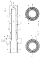
Figur 2- einen Längsschnitt durch den Tieflochbohrer;
Figur 3- einen Querschnitt durch den hinteren Teil des Tieflochbohrers;
- Figur 4
- einen Querschnitt durch den vorderen Teil des Tieflochbohrers;
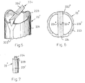
- Figur 5
- eine perspektifische Darstellung einer bevorzugten Ausführungsform des Kernbohrers;
- Figur 6
- eine Darstellung desselben Kernbohrers von oben;
Figur 7- eine Darstellung des Kernbohrers nach Figur 5 von der Seite.
- Figure 1
- a schematic representation of the deep hole drilling machine with deep hole drill from the side;
- Figure 2
- a longitudinal section through the deep hole drill;
- Figure 3
- a cross section through the rear part of the deep hole drill;
- Figure 4
- a cross section through the front part of the deep hole drill;
- Figure 5
- a perspective view of a preferred embodiment of the core drill;
- Figure 6
- a representation of the same core drill from above;
- Figure 7
- a representation of the core drill of Figure 5 from the side.
Obwohl der Schwerpunkt der Erfindung im Verfahren zur Herstellung von tiefen Bohrlöchern liegt, wird im folgenden das Ausführungsbeispiel der Tieflochbohrmaschine mit Tieflochbohrer näher beschrieben. Dies geschieht aus Gründen der Klarheit.Although the focus of the invention lies in the method for producing deep boreholes, the exemplary embodiment of the deep hole drilling machine with deep hole drill is described in more detail below. This is done for the sake of clarity.
Die Tieflochbohrmaschine zum Bohren von tiefen Löchern besteht im wesentlichen, wie dies in Figur 1 ersichtlich ist, aus einer Bohrvorrichtung A, einer Vorschubvorrichtung B und einem Rahmen, der hier nicht eingezeichnet ist. Die Vorrichtungen A, B sind auf dem Rahmen fixiert. Die Bohrvorrichtung A führt die Drehbewegung des Bohrers aus und gewährleistet die Wegführung der Späne mittels einer nicht dargestellten Druckluftzufuhr. Die Vorschubvorrichtung B erzeugt den Vorschub der Bohrvorrichtung A und bestimmt die Tiefe der Bohrung.The deep hole drilling machine for drilling deep holes essentially consists, as can be seen in FIG. 1, of a drilling device A, a feed device B and a frame, which is not shown here. The devices A, B are fixed on the frame. The drilling device A performs the rotary movement of the drill and ensures that the chips are guided away by means of a compressed air supply, not shown. The feed device B generates the feed of the drilling device A and determines the depth of the bore.
In der Vorschubvorrichtung B treibt ein Vorschubmotor 5 über ein Getriebe eine Transmission in Form einer geschlossenen Kette 6 an. An dieser Kette 6 ist ein Trägerelement 4 befestigt, das die Bohrvorrichtung A trägt. Anhand dieser Vorschubvorrichtung B lässt sich der gewünschte Vorschub der Bohrvorrichtung A verwirklichen. Ebenfalls lässt sich elektronisch oder mechanisch die Bohrlochtiefe einstellen. Die Vorrschubvorrichtung B lässt sich aus handelsüblichen Teilen zusammensetzen, wobei ihr Aufbau beliebig gewählt werden kann. Sie kann auch mittels Pressluft betrieben werden.In the feed device B, a feed motor 5 drives a transmission in the form of a closed chain 6 via a gear. A carrier element 4, which carries the drilling device A, is fastened to this chain 6. Using this feed device B, the desired feed of the drilling device A can be achieved. The borehole depth can also be set electronically or mechanically. The feed device B can be assembled from commercially available parts, and its structure can be chosen as desired. It can also be operated using compressed air.
Die Bohrvorrichtung A besteht aus einem Antriebsmotor 1 und einem Tieflochbohrer 2. Der Antriebsmotor 1 besitzt eine Hohlwelle. Er treibt den Tieflochbohrer 2 an.The drilling device A consists of a
Der Tieflochbohrer 2 setzt sich aus zwei konzentrisch ineinander angeordneten, langen, ein- oder mehrteiligen Hohlschäften zusammen, die die Bohrelemente bilden. Der Aussendurchmesser des inneren Hohlschaftes 22 entspricht dem Innendurchmesser des äusseren Hohlschaftes 21, wie in Figur 3 erkennbar ist.The
Der äussere Hohlschaft 21 ist mit dafür üblichen Befestigungsmitteln am Antriebsmotor 1 befestigt und ragt auf dessen dem Werkstück zugewandten Seite, im folgenden Bohrerseite genannt, mindestens um die Länge der gewünschten Bohrung heraus. Der innere Hohlschaft 22 durchsetzt die Hohlwelle des Antriebmotors 1, ragt also auf beiden Seiten desselben, der Bohrerseite und der Rückseite, heraus. Die zwei Hohlschäfte 21, 22 werden mit verschiedenen Uebersetzungen betrieben: der äussere Hohlschaft 21 mit einer grossen Uebersetzung 11, der innere Hohlschaft 22 mit einer kleinen Uebersetzung 12. Der innere Hohlschaft 22 weist also eine grössere Drehzahl auf als der äussere Hohlschaft 21. Sie unterscheidet sich im allgemeinen um den Faktor 90 von der Drehzahl des äusseren Hohlschaftes.The outer
Nahe dem Werkstück W ist der Tieflochbohrer 2 in einem Führungselement 3 verschiebbar gelagert. Dieses kann beispielsweise am hier nicht eingezeichneten Rahmen der Bohrmaschine befestigt sein. Das Führungselement 3 gewährleistet vorallem zu Beginn der Bohrung die Stabilität des Tieflochbohrers 2 und führt ihn während der gesamten Bearbeitungszeit.The
Der äussere Hohlschaft 21 weist in der Nähe des Antriebmotors 1 auf der Bohrerseite in einem definierten Bereich gleichmässig über seinen Umfang verteilte Oeffnungen 21'' auf, wie in Figur 2 ersichtlich ist. Ueber diesem Bereich befindet sich eine Presslufteinheit 23.The outer
Der innere Hohlschaft 22 weist symmetrisch auf seinem Umfang verteilte Längsrillen 222 auf, die von demselben Bereich an bis zum bohrerseitigen Ende des Hohlschaftes verlaufen. Diese Längsrillen 222 werden durch Abschleifen des Mantels des inneren Hohlschaftes 22 erzeugt. Im so entstandenen Bereich zwischen den zwei Hohlschäften befinden sich symmetrisch verteilte Zufuhrkanäle 24, wie in Figur 4 eingezeichnet.The inner
Die bohrerseitigen Enden beider Hohlschäfte sind mit Schneidelementen versehen. Der äussere Hohlschaft weist eine Bohrkrone 21' auf, der innere Hohlschaft einen Kernbohrer 22'. Der Kernbohrer 22' des inneren Hohlschaftes 22 ist gegenüber der Bohrkrone 21' des äusseren Hohlschaftes 21 zurückversetzt oder fluchtet mit dieser. Keinesfalls überragt er die Bohrkrone 21'. Dadurch ist erreicht, dass das innere Bohrelement dem äusseren Bohrelement nachläuft. Der äussere und der innere Hohlschaft sind beide vorzugsweise mehrteilig gefertigt. Die Bohrkrone 21' und der Kernbohrer 22' sind auf einzelnen, kurzen Hohlzylindern angeformt, die auf die langen Teile der Hohlschäfte 21,22 aufgesetzt werden. Auf diesen so gebildeten Bohrköpfen sind die eigentlichen Schneiden, vorzugsweise aus Hartmetall, aufgeschweisst oder gelötet. Im Falle der Bohrkrone ist diese Hartmetallschneide ein Zahnkranz, im Falle des Kernbohrers eine spezielle Schneideplatte. Die Schneiden können nachgeschliffen werden, ohne dass die ganzen Hohlschäfte demontiert werden müssen.The drill ends of both hollow shanks are provided with cutting elements. The outer hollow shaft has a drill bit 21 ', the inner hollow shaft has a core drill 22'. The core drill 22 'of the inner
Im Betriebszustand bohrt die Bohrkrone 21' einen Zapfen aus dem Werkstück. Sie führt den Tieflochbohrer 2 und verhindert durch seine Form ein Verlaufen desselben. Der Kernbohrer 22' kann verschiedenartige Schneiden aufweisen. Der Kernbohrer 22' entfernt den Kern oder Zapfen der Bohrung. Durch seine schnelle Rotation zerspant er nicht nur den Kern in kleinste Stücke, sondern zermahlt auch die eher grossen Späne, die durch die Rotation der Bohrkrone 21' des äusseren Hohlschaftes 21 entstanden sind.In the operating state, the drill bit 21 'drills a pin from the workpiece. It guides the
Im folgenden wird eine bevorzugte Ausführungsform des Kernbohrers 22' beschrieben. Damit der Tieflochbohrer auch bei Hölzern mit stark ausgeprägten Jahrringen, beziehungsweise in Bereiche mit Aesten, nicht verläuft, wird ein spezieller Kernbohrer 22' eingesetzt. Wählt man einen zu einer Spitze geformten Kernbohrer, so besteht die Gefahr, dass er markanten Jahrringen im Holz nachfährt und der Tieflochbohrer trotz der Führung der Bohrkrone verläuft. Der erfindungsgemässe Kernbohrer 22' weist deshalb keine Spitze, sondern eine senkrecht zur Längsrichtung angeordnete Schneide auf. Sie ist in den Figuren 5, 6 und 7 dargestellt.A preferred embodiment of the core drill 22 'is described below. A special core drill 22 'is used so that the deep hole drill does not run even in woods with strongly pronounced annual rings or in areas with knots. If you choose a core drill shaped to a point, there is a risk that it will trap distinctive tree rings in the wood and the deep hole drill will run despite the guidance of the drill bit. The core drill 22 'according to the invention therefore has no tip, but a cutting edge arranged perpendicular to the longitudinal direction. It is shown in Figures 5, 6 and 7.
Der Kernbohrer 22' besteht aus einem kurzen, den Bohrkopf bildenden Hohlzylinder, der an einem Ende ein Innengewinde aufweist. Damit kann er auf das entsprechende Aussengewinde des inneren Hohlschaftes 22 geschraubt werden. Am anderen Ende befinden sich die Schneidelemente, deren Schneidkanten in den Figuren mit dünnen Linien dargestellt sind. Als untergeordnete Schneidelemente dienen zwei periphere Schulterpartien 223, die diametral zueinander angeordnet sind und gegenüber dem Mantel 221 des Hohlzylinders in Schneidkanten zulaufen. Um 90° zu der Verbindungsdiagonalen der Schulterpartien 223 gedreht, überbrückt eine Schneide 224 in Form einer Platte diagonal den Hohlzylinder. Die Schneide 224 überragt die peripheren Schulterpartien 223 und dient als wesentliches Zerspanungselement. Sie besteht aus zwei Hauptschneiden 224', die zentrosymmetrisch um die Bohrerachse angeordnet sind und deren Schneidkanten parallel zur Diagonalen liegen. Die Schneidkante der einen Hauptschneide 224' liegt also auf der einen Seite der Diagonalen, die Schneidkante der anderen Hauptschneide auf der anderen Seite. Beide Hauptschneiden 224' weisen den gleichen, aber entgegengesetzten Neigungswinkel bezüglich der Bohrerachse auf. Da die Schneidkanten annähernd senkrecht zur Bohrerachse liegen, arbeiten die Hauptschneiden 224' ähnlich einer Planfräse. Im Bereich der Bohrerachse gehen die Hauptschneiden 224' entlang ihrer Neigung je in eine Nebenschneide 224'' über. Diese verlaufen ebenfalls zentrosymmetrisch zur Bohrerachse und schliessen in der Neigungsebene mit den Schneidkanten einen spitzen Winkel ein.The core drill 22 'consists of a short hollow cylinder forming the drill head, which has an internal thread at one end. So that it can be screwed onto the corresponding external thread of the inner
Die zwei Ansätze der Schneide 224 auf dem Hohlzylinder sind gegenüber dem oberen Bereich der Schneide 224 verjüngt. Der Hohlzylinder weist vier symmetrisch auf der Aussenmantelfläche verteilte Längsrillen 222' auf, die sich über die gesamte Länge des Hohlzylinders erstrecken. Je eine Längsrille 222' endet an der Schneidkante einer peripheren Schulterpartie 223. Um 90° versetzt verlaufen die anderen zwei Längsrillen 222' bis in den Bereich der Ansätze der Schneide. In diesem Bereich verzweigen sich die zwei Längsrillen 222' v-förmig und enden je auf einer Seite des Ansatzes.
Selbstverständlich müssen die der Luftzuführung dienenden Längsrillen 222' mit jenen der am Bohrkopf anschliessenden, mehrteiligen Verlängerungsteile des Hohlschaftes 22 fluchten.The two lugs of the
Of course, the longitudinal grooves 222 'used for the air supply must be aligned with those of the multi-part extension parts of the
Durch die Pressluftzufuhreinheit 23 wird von aussen Pressluft zugeführt. Sie strömt durch die Zufuhrkanäle 24 zwischen den zwei Hohlschäften 21, 22 bis zum bohrerseitigen Ende des Tieflochbohrers 2 in die Bohrung. Dabei kühlt sie beide Hohlschäfte mit den integrierten oder aufgesetzten Schneidelementen. Gleichzeitig wird der innere Hohlschaft 22 durch das Luftkissen gelagert. Als Abfuhrkanal 25 dient der Kern des inneren Hohlschaftes 22. Die Luft entweicht durch diesen Abfuhrkanal 25 und führt als Kühl- und Transportmedium zugleich das abgespante Material des Werkstückes von der Bohrstelle nach aussen weg. Die Späne werden auf der Rückseite des Antriebsmotors aus dem inneren Hohlschaft 21 geblasen. Die spezielle Form des Kernbohrers 22' optimiert die Luftverteilung an der Bohrstelle. Die Längsrillen 222' an den peripheren Schulterpartien 223 führen die Luft in die Nähe der Bohrkrone 21' des äusseren Hohlschaftes 21, damit das dort abgetragene Material erfasst wird. Die verzweigten Längsrillen 222' bei den Ansätzen der Schneide 224 erfassen vorallem die durch die Schneide 224 und die peripheren Schulterpartien 223 erzeugten Späne.Compressed air is supplied from the outside through the compressed
Durch das Verfahren, das mittels dieser Bohrmaschine mit Tieflochbohrer angewandt wird, ist der Fluss beim Abtransport der Späne gewährleistet. Die Späne werden durch den Kernbohrer 22' auf Abmessungen zerkleinert, die sehr viel kleiner als der Durchmesser des Abfuhrkanals 25 sind. Zudem wird eine Verklumpung der feinen Späne, bzw. Sägemehl, verhindert, indem durch die schnelle Rotationsbewegung und die Anordnung der Längsrillen 222' des Kernbohrers 22' Luftwirbel erzeugt werden, auf denen die Späne als Einzelteile mitgetragen werden.The process used by this drill with deep hole drill ensures the flow when the chips are removed. The chips are comminuted by the
Mit diesem Verfahren ist es somit möglich, sehr tiefe Löcher mit typischen Längen von 1 - 2 Metern ohne Unterbruch des Arbeitsvorganges zu bohren. Einerseits wird das Verlaufen des Bohrers durch die Form und Lage der Bohrkrone 21' des äusseren Schaftes 21 und die spezielle Form des Kernbohrers 22' des inneren Schaftes 22 verhindert. Andererseits ist der Abtransport der Späne durch den Verlauf des Kühl- und Transportmediums und der Funktion des Kernbohrers gewährleistet.With this method it is possible to drill very deep holes with typical lengths of 1 - 2 meters without interrupting the work process. On the one hand, the shape and position of the drill bit 21 'of the
Claims (19)
- A method for producing deep holes, particularly in wood and similar structural materials, characterized in that two drilling members (21, 22) arranged concentrically within one another and constructed as hollow shanks with ends having cutting members (224) are operated at different speeds, the inner drilling member (22) trailing behind the outer drilling member (21).
- A method according to claim 1, characterized in that the outer drilling member (21) is operated at a lower speed than the inner drilling member (22).
- A method according to claim 2, characterized in that the speed of the inner drilling member (22) is 10 to 200 times higher than the speed of the outer drilling member (21).
- A method according to claim 1, characterized in that a cooling and transfer medium is introduced between the drilling members (21, 22) from the outside, that said cooling and transfer medium then flows between the drilling members (21, 22) up to the drilling point and from there flows back in the core of the inner drilling member (22) entrained with removed material.
- A deep hole drill for performing the method according to claim 1, comprising two independently rotatable hollow shanks (21, 22) arranged concentrically within one another, one end of each of these having cutting members, the end of the inner hollow shank (22) provided with the cutting members being set back with respect to the end of the outer hollow shank (21).
- A deep hole drill according to claim 5, characterized in that between the hollow shanks (21, 22) is at least one supply channel (24) for a cooling and transfer medium and the core of the inner hollow shank has a removal channel (25) for said cooling and transfer medium.
- A deep hole drill according to claim 5, characterized in that an area of the outer hollow shank (21) has openings (21'') for the supply of the cooling and transfer medium.
- A deep hole drill according to claim 7, characterized in that the inner hollow shank (22), from the same area and up to its cutting members, has symmetrically arranged, circumferentially distributed longitudinal grooves (222).
- A deep hole drill according to claim 5, characterized in that the hollow shanks (21, 22) are in multipart form.
- A deep hole drill according to claim 5, characterized in that the cutting member of the outer hollow shank (21) is constructed as a drill bit (21').
- A deep hole drill according to claim 5, characterized in that the cutting member of the inner hollow shank (22) is constructed as a hollow cylindrical core drill (22').
- A deep hole drill according to claim 11, characterized in that the core drill (22') has a cutting lip (224) diagonally bridging the hollow cylinder and with cutting edges (224') approximately perpendicular to the drill axis.
- A deep hole drill according to claim 12, characterized in that the core drill (22') has two peripheral shoulder portions (223) provided with cutting edges and which are in each case turned by 90° with respect to the cutting lip (224) and that the cutting lip (224) projects over the shoulder portions (223).
- A deep hole drill according to claims 13 and 8, characterized in that at least one of the symmetrically distributed longitudinal grooves (222') around the circumference of the core drill (22') extends over and beyond the peripheral shoulder portions (223) and that in each case one V-shaped branched longitudinal groove (222') emerges at a step of the cutting lip (224) on the hollow cylinder.
- A deep hole drilling machine, which is provided with a deep hole drill according to claim 5.
- A deep hole drilling machine according to claim 15, characterized in that its drive motor (1) has a hollow shaft.
- A deep hole drilling machine according to claim 16, characterized in that the inner hollow shank (22) projects to either side of the drive motor (1) and the free end of its cutting member is open.
- A deep hole drilling machine according to claim 17, characterized in that its deep hole drill (2) is displaceably mounted in a rigid guide member (3) positioned close to the workpiece (W).
- A deep hole drilling machine according to claim 18, characterized in that it is provided with a standard feed mechanism (B) for such purposes.
Applications Claiming Priority (5)
| Application Number | Priority Date | Filing Date | Title |
|---|---|---|---|
| CH256192 | 1992-08-17 | ||
| CH2561/92 | 1992-08-17 | ||
| CH367792 | 1992-12-01 | ||
| CH3677/92 | 1992-12-01 | ||
| PCT/CH1993/000194 WO1994004303A1 (en) | 1992-08-17 | 1993-08-03 | Deep-boring drill |
Publications (2)
| Publication Number | Publication Date |
|---|---|
| EP0617649A1 EP0617649A1 (en) | 1994-10-05 |
| EP0617649B1 true EP0617649B1 (en) | 1996-06-26 |
Family
ID=25690775
Family Applications (1)
| Application Number | Title | Priority Date | Filing Date |
|---|---|---|---|
| EP93915624A Expired - Lifetime EP0617649B1 (en) | 1992-08-17 | 1993-08-03 | Deep-boring drill |
Country Status (7)
| Country | Link |
|---|---|
| US (1) | US5451126A (en) |
| EP (1) | EP0617649B1 (en) |
| AT (1) | ATE139719T1 (en) |
| CA (1) | CA2121576A1 (en) |
| DE (1) | DE59303074D1 (en) |
| FI (1) | FI941742A0 (en) |
| WO (1) | WO1994004303A1 (en) |
Families Citing this family (23)
| Publication number | Priority date | Publication date | Assignee | Title |
|---|---|---|---|---|
| DE4430331A1 (en) * | 1994-08-28 | 1996-02-29 | Schwaebische Huettenwerke Gmbh | Method and device for influencing the course of deep hole drilling |
| DE19648868A1 (en) * | 1996-11-26 | 1998-05-28 | Hilti Ag | Drilling tool with a hollow cylindrical support body |
| CN1079308C (en) * | 1999-03-24 | 2002-02-20 | 叶小宁 | Processing method of superlong precision deep bore and its equipment |
| DE10222040A1 (en) * | 2002-05-17 | 2003-12-04 | Kennametal Inc | milling tool |
| US20050105980A1 (en) * | 2003-02-28 | 2005-05-19 | Davis John D. | I-joist hole cutting apparatus |
| US6857831B2 (en) * | 2003-02-28 | 2005-02-22 | John D. Davis | I-joist hole cutting apparatus |
| SE526387C2 (en) * | 2003-05-08 | 2005-09-06 | Seco Tools Ab | Drill bit for chip removal machining with all parts made of a material and with enclosed coil channel |
| US7563060B2 (en) * | 2005-10-13 | 2009-07-21 | The Boeing Company | Vacuum drilling system |
| US20090031871A1 (en) * | 2006-06-08 | 2009-02-05 | Malandain Hugues F | Dual cutting element tool for debulking bone |
| WO2009006042A1 (en) * | 2007-06-29 | 2009-01-08 | Allied Machine & Engineering Corp. | Ejector drill system |
| US20090136309A1 (en) * | 2007-11-28 | 2009-05-28 | Coulston George W | Apparatus and method for chip evacuation |
| US7950883B2 (en) * | 2008-02-04 | 2011-05-31 | Yuehting Chen | Compact engraving machine |
| US20100030216A1 (en) * | 2008-07-30 | 2010-02-04 | Arcenio Gregory B | Discectomy tool having counter-rotating nucleus disruptors |
| US8286731B2 (en) * | 2008-10-22 | 2012-10-16 | Ressi Di Cervia Arturo L | Method and apparatus for constructing deep vertical boreholes and underground cut-off walls |
| GB201014811D0 (en) * | 2010-09-07 | 2010-10-20 | Enviroform Solutions Ltd | Tool |
| JP6165974B2 (en) * | 2013-05-28 | 2017-07-19 | アライド マシーン アンド エンジニアリング コーポレーションAllied Machine & Engineering Corporation | Vacuum drilling system and method |
| US9346111B2 (en) * | 2013-07-26 | 2016-05-24 | E.R. Shaw Inc. | Machine to manufacture gun barrels and method of using |
| DE102013110129A1 (en) * | 2013-09-13 | 2015-03-19 | Jakob Lach Gmbh & Co. Kg | Tool arrangement for the production of boreholes in materials such as fiber composites |
| US10040155B2 (en) * | 2016-01-19 | 2018-08-07 | The Boeing Company | Air cooled spindle exhaust air redirection system for enhanced machining byproduct recovery |
| US10442011B1 (en) | 2017-11-20 | 2019-10-15 | Me3, Inc | Modular flywheel holesaw system |
| USD851145S1 (en) | 2017-11-20 | 2019-06-11 | John D. Davis | Modular flywheel holesaw |
| CN112372024A (en) * | 2020-08-27 | 2021-02-19 | 沈阳富创精密设备股份有限公司 | Method for machining deep hole with diameter more than 30 times by using inner-cooling drill bit |
| CN117139684B (en) * | 2023-10-30 | 2023-12-29 | 成都天科航空制造股份有限公司 | Hinge drilling device and drilling method for wing part |
Family Cites Families (18)
| Publication number | Priority date | Publication date | Assignee | Title |
|---|---|---|---|---|
| DE375970C (en) * | 1923-05-22 | Bergbau Ind Und Bahnbau Ges | Process for the production of wooden pipes from a log | |
| US106077A (en) * | 1870-08-02 | Improvement in pipe-boring machine | ||
| US1352825A (en) * | 1916-12-19 | 1920-09-14 | R H White | Boring-tool |
| CH133263A (en) * | 1928-03-12 | 1929-05-31 | Gewerkschaft Kleinholz Weber | Method and lathe for turning a pipe out of a log. |
| US1940220A (en) * | 1931-02-06 | 1933-12-19 | Finkl & Sons Co | Boring tool |
| BE519534A (en) * | 1953-05-06 | |||
| US3584534A (en) * | 1969-04-11 | 1971-06-15 | Everett D Hougen | Device for driving a hole cutter |
| GB1415137A (en) * | 1974-05-14 | 1975-11-26 | Blanson Precision Cutting Tool | Deep hole drill |
| US3976387A (en) * | 1975-06-02 | 1976-08-24 | Segal F | Hole saw drill and arbor assembly |
| US4204783A (en) * | 1979-03-01 | 1980-05-27 | Hougen Everett D | Machine for cutting holes with annular cutters |
| US4339857A (en) * | 1980-08-11 | 1982-07-20 | Dickinson Lawrence C | Integrated cylinder finishing system |
| US4306570A (en) * | 1980-08-20 | 1981-12-22 | Matthews Larry S | Counter rotating biopsy needle |
| US4362444A (en) * | 1980-10-10 | 1982-12-07 | Watkins John A | Peck drill |
| AU567784B2 (en) * | 1983-12-15 | 1987-12-03 | William James McGuire | Dowell making machine |
| DE3424630C2 (en) * | 1984-07-04 | 1986-06-19 | Oerlikon-Boehringer GmbH, 7320 Göppingen | Feed device for deep drilling |
| SU1214448A1 (en) * | 1984-09-27 | 1986-02-28 | Предприятие П/Я Ж-1287 | Tool for machining fibrous composite materials |
| DE3529603A1 (en) * | 1985-08-19 | 1987-03-05 | Will E C H Gmbh & Co | Boring tool for quires of paper or the like |
| DE69007241T2 (en) * | 1989-11-25 | 1994-06-23 | Omi Kogyo Kk | Hollow drill. |
-
1993
- 1993-08-03 DE DE59303074T patent/DE59303074D1/en not_active Expired - Fee Related
- 1993-08-03 WO PCT/CH1993/000194 patent/WO1994004303A1/en active IP Right Grant
- 1993-08-03 EP EP93915624A patent/EP0617649B1/en not_active Expired - Lifetime
- 1993-08-03 AT AT93915624T patent/ATE139719T1/en not_active IP Right Cessation
- 1993-08-03 US US08/211,805 patent/US5451126A/en not_active Expired - Fee Related
- 1993-08-03 CA CA002121576A patent/CA2121576A1/en not_active Abandoned
-
1994
- 1994-04-15 FI FI941742A patent/FI941742A0/en not_active Application Discontinuation
Also Published As
| Publication number | Publication date |
|---|---|
| CA2121576A1 (en) | 1994-03-03 |
| DE59303074D1 (en) | 1996-08-01 |
| ATE139719T1 (en) | 1996-07-15 |
| FI941742A (en) | 1994-04-15 |
| FI941742A0 (en) | 1994-04-15 |
| EP0617649A1 (en) | 1994-10-05 |
| US5451126A (en) | 1995-09-19 |
| WO1994004303A1 (en) | 1994-03-03 |
Similar Documents
| Publication | Publication Date | Title |
|---|---|---|
| EP0617649B1 (en) | Deep-boring drill | |
| EP0103235B1 (en) | Drill | |
| EP2830799B1 (en) | Drill bit | |
| DE3610016C2 (en) | ||
| DE4326023A1 (en) | Device for supplying liquid to a tool | |
| CH678834A5 (en) | ||
| EP0334002B1 (en) | Thread milling cutter | |
| DE1477708A1 (en) | Machining rotary drill | |
| DE2411394B2 (en) | Drill head | |
| CH635256A5 (en) | DRILLING TOOL. | |
| DD279199A5 (en) | DEVICE FOR PRODUCING INTERNAL THREADS | |
| DE4212709C2 (en) | Tool with an interchangeable cutting body with a cylindrical shank for machining, primarily in metalworking | |
| DE3413108A1 (en) | RING HOLE CUTTER | |
| EP0358901A1 (en) | Boring tool, especially a metal-boring tool | |
| AT391646B (en) | DRILL | |
| DE19710996A1 (en) | Drilling tool with cutting inserts | |
| DE2234825A1 (en) | METHOD AND TOOL FOR MAKING HOLES | |
| DE3742740C1 (en) | Fine boring tool | |
| DE3629033C2 (en) | ||
| EP0123787B1 (en) | Tool for boring deep holes | |
| DE1911594A1 (en) | Drilling tools, in particular metal drills | |
| DE2420204A1 (en) | Large diameter hollow boring tool - leaves inner core during cutting process | |
| DE2362395A1 (en) | Building blocks mfr - using milling cutters to obtain exact dimension on block height | |
| DE2715234A1 (en) | SELF-LIFTING TOOL CLAMP | |
| DE10147649A1 (en) | Milling unit for groove work has two or more tools rotated via bearings off main spindle and swivels tool to adjust tool angle to suit milling unit vector. |
Legal Events
| Date | Code | Title | Description |
|---|---|---|---|
| PUAI | Public reference made under article 153(3) epc to a published international application that has entered the european phase |
Free format text: ORIGINAL CODE: 0009012 |
|
| 17P | Request for examination filed |
Effective date: 19940323 |
|
| AK | Designated contracting states |
Kind code of ref document: A1 Designated state(s): AT BE CH DE DK ES FR GB GR IT LI NL PT SE |
|
| 17Q | First examination report despatched |
Effective date: 19950911 |
|
| GRAH | Despatch of communication of intention to grant a patent |
Free format text: ORIGINAL CODE: EPIDOS IGRA |
|
| GRAH | Despatch of communication of intention to grant a patent |
Free format text: ORIGINAL CODE: EPIDOS IGRA |
|
| GRAA | (expected) grant |
Free format text: ORIGINAL CODE: 0009210 |
|
| AK | Designated contracting states |
Kind code of ref document: B1 Designated state(s): AT BE CH DE DK ES FR GB GR IT LI NL PT SE |
|
| PG25 | Lapsed in a contracting state [announced via postgrant information from national office to epo] |
Ref country code: NL Free format text: LAPSE BECAUSE OF FAILURE TO SUBMIT A TRANSLATION OF THE DESCRIPTION OR TO PAY THE FEE WITHIN THE PRESCRIBED TIME-LIMIT Effective date: 19960626 Ref country code: IT Free format text: LAPSE BECAUSE OF FAILURE TO SUBMIT A TRANSLATION OF THE DESCRIPTION OR TO PAY THE FEE WITHIN THE PRESCRIBED TIME-LIMIT;WARNING: LAPSES OF ITALIAN PATENTS WITH EFFECTIVE DATE BEFORE 2007 MAY HAVE OCCURRED AT ANY TIME BEFORE 2007. THE CORRECT EFFECTIVE DATE MAY BE DIFFERENT FROM THE ONE RECORDED. Effective date: 19960626 Ref country code: GR Free format text: LAPSE BECAUSE OF FAILURE TO SUBMIT A TRANSLATION OF THE DESCRIPTION OR TO PAY THE FEE WITHIN THE PRESCRIBED TIME-LIMIT Effective date: 19960626 Ref country code: GB Effective date: 19960626 Ref country code: FR Effective date: 19960626 Ref country code: ES Free format text: THE PATENT HAS BEEN ANNULLED BY A DECISION OF A NATIONAL AUTHORITY Effective date: 19960626 Ref country code: DK Effective date: 19960626 |
|
| REF | Corresponds to: |
Ref document number: 139719 Country of ref document: AT Date of ref document: 19960715 Kind code of ref document: T |
|
| REF | Corresponds to: |
Ref document number: 59303074 Country of ref document: DE Date of ref document: 19960801 |
|
| PG25 | Lapsed in a contracting state [announced via postgrant information from national office to epo] |
Ref country code: BE Effective date: 19960831 |
|
| PG25 | Lapsed in a contracting state [announced via postgrant information from national office to epo] |
Ref country code: SE Effective date: 19960926 Ref country code: PT Effective date: 19960926 |
|
| REG | Reference to a national code |
Ref country code: CH Ref legal event code: NV Representative=s name: PATENTANWALTSBUERO FELDMANN AG |
|
| EN | Fr: translation not filed | ||
| NLV1 | Nl: lapsed or annulled due to failure to fulfill the requirements of art. 29p and 29m of the patents act | ||
| GBV | Gb: ep patent (uk) treated as always having been void in accordance with gb section 77(7)/1977 [no translation filed] |
Effective date: 19960626 |
|
| PLBE | No opposition filed within time limit |
Free format text: ORIGINAL CODE: 0009261 |
|
| STAA | Information on the status of an ep patent application or granted ep patent |
Free format text: STATUS: NO OPPOSITION FILED WITHIN TIME LIMIT |
|
| 26N | No opposition filed | ||
| PGFP | Annual fee paid to national office [announced via postgrant information from national office to epo] |
Ref country code: DE Payment date: 20000117 Year of fee payment: 7 |
|
| PGFP | Annual fee paid to national office [announced via postgrant information from national office to epo] |
Ref country code: AT Payment date: 20000125 Year of fee payment: 7 |
|
| PGFP | Annual fee paid to national office [announced via postgrant information from national office to epo] |
Ref country code: CH Payment date: 20000224 Year of fee payment: 7 |
|
| PG25 | Lapsed in a contracting state [announced via postgrant information from national office to epo] |
Ref country code: AT Free format text: LAPSE BECAUSE OF NON-PAYMENT OF DUE FEES Effective date: 20000803 |
|
| PG25 | Lapsed in a contracting state [announced via postgrant information from national office to epo] |
Ref country code: LI Free format text: LAPSE BECAUSE OF NON-PAYMENT OF DUE FEES Effective date: 20000831 Ref country code: CH Free format text: LAPSE BECAUSE OF NON-PAYMENT OF DUE FEES Effective date: 20000831 |
|
| REG | Reference to a national code |
Ref country code: CH Ref legal event code: PL |
|
| PG25 | Lapsed in a contracting state [announced via postgrant information from national office to epo] |
Ref country code: DE Free format text: LAPSE BECAUSE OF NON-PAYMENT OF DUE FEES Effective date: 20010501 |