EP0617444B1 - Deceleration sensor switch for use in a vehicle occupant safety system - Google Patents
Deceleration sensor switch for use in a vehicle occupant safety system Download PDFInfo
- Publication number
- EP0617444B1 EP0617444B1 EP94104621A EP94104621A EP0617444B1 EP 0617444 B1 EP0617444 B1 EP 0617444B1 EP 94104621 A EP94104621 A EP 94104621A EP 94104621 A EP94104621 A EP 94104621A EP 0617444 B1 EP0617444 B1 EP 0617444B1
- Authority
- EP
- European Patent Office
- Prior art keywords
- mass
- sensor switch
- deceleration sensor
- contact
- rod portion
- Prior art date
- Legal status (The legal status is an assumption and is not a legal conclusion. Google has not performed a legal analysis and makes no representation as to the accuracy of the status listed.)
- Expired - Lifetime
Links
Images



Classifications
-
- H—ELECTRICITY
- H01—ELECTRIC ELEMENTS
- H01H—ELECTRIC SWITCHES; RELAYS; SELECTORS; EMERGENCY PROTECTIVE DEVICES
- H01H35/00—Switches operated by change of a physical condition
- H01H35/06—Switches operated by change of speed
-
- H—ELECTRICITY
- H01—ELECTRIC ELEMENTS
- H01H—ELECTRIC SWITCHES; RELAYS; SELECTORS; EMERGENCY PROTECTIVE DEVICES
- H01H35/00—Switches operated by change of a physical condition
- H01H35/14—Switches operated by change of acceleration, e.g. by shock or vibration, inertia switch
-
- H—ELECTRICITY
- H01—ELECTRIC ELEMENTS
- H01H—ELECTRIC SWITCHES; RELAYS; SELECTORS; EMERGENCY PROTECTIVE DEVICES
- H01H1/00—Contacts
- H01H1/12—Contacts characterised by the manner in which co-operating contacts engage
- H01H1/14—Contacts characterised by the manner in which co-operating contacts engage by abutting
- H01H1/18—Contacts characterised by the manner in which co-operating contacts engage by abutting with subsequent sliding
Definitions
- the present invention relates to a deceleration sensor switch, and is particularly directed to a deceleration sensor switch comprising an inertia mass which moves against a spring bias in response to a predetermined deceleration.
- Deceleration sensor switches which include an inertia mass which moves against a spring bias in response to a predetermined deceleration are known.
- One known deceleration sensor switch includes a donut-shaped inertial mass slidable on a rod against a spring bias.
- Another known deceleration sensor switch includes a mass disposed in a cylindrical chamber in a body and movable in the chamber against a spring bias. Also, some of the known deceleration sensor switches have means for adjusting the spring bias to adjust the responsiveness of the deceleration sensor switch.
- a deceleration sensor switch comprises a mass mounted on a rod portion and movable relative to the rod portion between an unactuated position and an actuated position along the longitudinal central axis of the rod portion.
- the mass moves from the unactuated position to the actuated position when the deceleration sensor switch is subjected to deceleration of a predetermined magnitude.
- the mass moves against a spring bias to provide a restoring force which acts on the mass to move the mass relative to the rod portion from the actuated position back to the unactuated position.
- the spring bias is provided by a helical coil spring helically wound around the rod portion along its longitudinal central axis.
- First and second electrical terminals are electrically connectable with each other.
- Connecting means is provided for electrically connecting the first and second electrical terminals with each other when the mass moves from the unactuated position to the actuated position.
- the connecting means comprises a contact including (i) a releasable tab portion which engages the mass when said mass is in the unactuated position and which is released for movement with the rectangular mass when the rectangular mass moves from the unactuated position to the actuated position, (ii) a biasing portion which biases the tab portion into engagement with the rectangular mass, and (iii) a contact portion which is spaced apart a predetermined distance from one of the first and second electrical terminals when the rectangular mass is in the unactuated position and which contacts the one electrical terminal when the rectangular mass is in the actuated position.
- the releasable tab portion includes means for enabling the contact portion to maintain the predetermined distance from the one electrical terminal upon movement of the rectangular mass in a direction perpendicular to the longitudinal central axis of the rod portion.
- a plate portion of the base includes a flat surface which is parallel with one side of a rectangular mass when said rectangular mass is mounted on the rod portion.
- the flat surface is spaced apart from the one side of the rectangular mass at a distance which prevents rotation of the rectangular mass about the longitudinal central axis of the rod portion.
- Protection tab means is disposed on the rectangular mass. The protection tab means prevents a cover engageable with the base from striking the connecting means when the cover is moved towards the base to engage the base. The cover engages the base to enclose the rectangular mass and the helical coil spring.
- the present invention is directed to a deceleration sensor switch comprising a mass which moves against a spring bias.
- a deceleration sensor switch in accordance with the present invention may be used in a variety of different systems.
- the deceleration sensor switch is used in a vehicle occupant safety system, such as an air bag system, to trigger inflation of an air bag in the event of vehicle deceleration indicative of a vehicle collision.
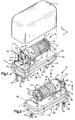
- a deceleration sensor switch 10 constructed in accordance with the present invention is shown in Fig. 1.
- the deceleration sensor switch 10 comprises a base 12.
- the base 12 includes a bottom plate portion 14 and a top plate portion 15 located above the bottom plate portion 14.
- the bottom plate portion 14 lies in a flat plane.
- the top plate portion 15 lies in another flat plane which is parallel to the flat plane in which the bottom plate portion 14 lies.
- the bottom plate portion 14 has a main body part 82, a first terminal support part 84 located adjacent one end of the main body part 82, and a second terminal support part 86 located adjacent an opposite end of the main body part 82.
- the first and second terminal support parts 84, 86 project away from the main body part 82.
- the bottom plate portion 14 is larger than the top plate portion 15.
- the top plate portion 15 overlies part of the bottom plate portion 14 in such a way that a ledge 94 of uniform width is formed around the outer periphery of the base 12.
- the top plate portion 15 has a side wall 95 which extends around the outer periphery of the top plate portion 15.
- the side wall 95 extends perpendicular to the ledge 94.
- a cover 11 (shown only in Fig. 1) is sealingly engageable against the side wall 95 of the top plate portion 15 and the ledge 94 of the bottom plate portion 14 to seal and protect the deceleration sensor switch 10.
- the base 12 further includes a horizontal pedestal portion 16 located above the top plate portion 15 and a vertical pedestal portion 17 located above the horizontal pedestal portion 16.
- the horizontal pedestal portion 16 overlies part of the-top plate portion 15 and the vertical pedestal portion 17 projects perpendicularly away from the horizontal pedestal portion 16.
- the vertical pedestal portion 17 has a first vertically projecting part 47 and a second vertically projecting part 49 which is smaller than the first vertically projecting part 47.
- a vertically extending slot 48 is defined between the first and second vertically projecting parts 47, 49 of the vertical pedestal portion 17.
- the base 12 further includes a tubular rod portion 18 spaced from the top plate portion 15 and cantilevered from the vertical pedestal portion 17.
- the rod portion 18 has a free end 19 (Fig. 1) and a longitudinal central axis 99 (Fig. 2) which extends parallel to the flat planes in which the top and bottom plate portions 14, 15 lie.
- the rod portion 18, the horizontal and vertical pedestal portions 16, 17, and the top and bottom plate portions 14, 15 are a single continuous piece of molded plastic material, as best shown in the sectional view of Fig. 3.
- a mass 20 is mounted on the rod portion 18 and is movable relative to the rod portion 18 between an unactuated position shown in Fig. 6 and an actuated position shown in Fig. 8 along the longitudinal central axis 99 of the rod portion 18.
- the mass 20 has a first ring-like portion 21 having a cross-sectional outer diameter and a second ring-like pilot portion 23 having a cross-sectional outer diameter smaller than the cross-sectional outer diameter of the first ring-like portion 21.
- the first and second ring-like portions 21, 23 are coaxial.
- a spring 22 in the form of a helical coil spring is helically wound around the rod portion 18 along its longitudinal central axis 99.
- the spring 22 has one end 90 (Fig. 2) and another end 91 (Fig. 1) located opposite the one end 90.
- the second ring-like pilot portion 23 of the mass 20 extends into the end 90 of the spring 22 to support and guide the spring 22.
- the end 90 of the spring 22 abuts against a ring-shaped surface 97 (Fig. 6) at one end of the first portion 21 of the mass 20.
- the spring bias of the spring 22 presses against the ring-shaped surface 97 of the first portion 21 of the mass 20 to press the mass 20 into engagement with the vertical pedestal portion 17.
- an adjustable calibration member 24 in the form of a threaded screw having a head portion 25 is screwed into the free end 19 of the rod portion 18.
- the rod portion 18 has a cylindrical hole 80 (shown only in Fig. 3) in which the threads of the threaded screw 24 engage.
- a washer 27 is located between the head portion 25 of the threaded screw 24 and the free end 19 of the rod portion 18.
- the washer 27 includes a ring-like pilot portion 70 and a ring-like flange portion 72 extending from the ring-like pilot portion 70.
- the ring-like portions 70, 72 are coaxial.
- the ring-like pilot portion 70 of the washer 27 extends into the end 91 of the spring 22 to support and guide the spring 22.
- the end 91 of the spring 22 abuts against a ring-shaped surface 71 (Fig. 4) on the ring-like flange portion 72 of the washer 27.
- the spring bias of the spring 22 presses against the ring-shaped surface 71 of the ring-like flange portion 72 of the washer 27 to press the washer 27 into engagement with the head portion 25 of the threaded screw 24.
- the threaded screw 24 is received in a hole 74 (Fig. 4) which extends through the ring-like pilot portion 70 of the washer 27.
- the threaded screw 24 can be rotated clockwise or counterclockwise to either move the washer 27 towards the free end 19 of the rod portion 18 or to allow the washer 27 to move away from the free end 19 of the rod portion 18 due to the spring bias of the spring 22 acting on the washer 27. Therefore, the position of the washer 27 relative to the free end 19 of the rod portion 18 can be adjusted by rotating the threaded screw 24 clockwise or counterclockwise.
- the spring bias of the spring 22 acting on the mass 20 depends upon the position of the washer 27 relative to the free end 19 of the rod portion 18. Thus, the spring bias of the spring 22 acting on the mass 20 can be adjusted by rotating the threaded screw 24 either clockwise or counterclockwise.
- the terminal 30 has bifurcated leg portions 32 which extend away from the first terminal support part 84 of the bottom plate portion 14.
- One of the leg portions 32 is connectable to a negative terminal of a voltage supply and the other one of the leg portions 32 is connectable to an external resistor for diagnostic purposes.
- the end of the terminal 30 opposite the leg portions 32 is one of a pair of electrical terminals of the deceleration sensor switch 10.
- Another terminal 34 also made of a suitable electrical current conducting material, preferably stainless steel, is insert molded into the horizontal pedestal portion 16, the top plate portion 15, the main body part 82 of the bottom plate portion 14, and the first terminal support part 84 of the bottom plate 14.
- the terminal 34 has bifurcated leg portions 36 which extend away from the first terminal support part 84 of the bottom plate portion 14.
- One of the leg portions 36 is connectable to a positive terminal of a voltage supply and the other one of the leg portions 36 is connectable to an external resistor for diagnostic purposes.
- the end of the terminal 34 opposite the leg portions 36 is the other one of the pair of electrical terminals of the deceleration sensor switch 10.
- a pair of leg portions 85 are insert molded into the second terminal support part 86.
- the leg portions 85 extend away from the second terminal support part 86 in the same direction as the leg portions 32 of the terminal 30 and the leg portions 36 of the terminal 34 extend away from the first terminal support part 84.
- the three leg portions 32, 36, 85 support the deceleration sensor switch 10 when the deceleration sensor switch 10 is mounted for use.
- a movable contact 40 made of stainless steel includes a releasable tab portion 42 and two generally parallel strip portions 44 extending from the tab portion 42.
- An edge 46 of the tab portion 42 extends through the vertically extending slot 48 defined between the first and second vertically projecting parts 47, 49 of the vertical pedestal portion 17.
- the contact 40 also includes an end portion 50 which interconnects the two parallel strip portions 44.
- the end portion 50 is welded to a flat surface 31 of the terminal 30 so that the two parallel strip portions 44 of the contact 40 extend horizontally, as viewed in Fig. 1.
- the two parallel strip portions 44 act like leaf springs to provide a spring-like force which presses the edge 46 of the tab portion 42 into contact with the first portion 21 of the mass 20.
- the contact 40 also has a contact portion 52 which extends from the tab portion 42 and is located between the two parallel strip portions 44, as best shown in Figs. 1, 5 and 6.
- the contact portion 52 has a pair of spring-like legs 53 (best shown in Fig. 5) which are contactable with a surface 35 (Figs. 1 and 5) of the terminal 34.
- the legs 53 of the contact portion 52 are not contacting the surface 35 of the terminal 34, the terminal 34 and the terminal 30 are not electrically connected.
- the deceleration sensor switch 10 is in a fully opened condition, as shown in Fig. 6.
- the first portion 21 of the mass 10 abuts against the vertical pedestal portion 17 and against the edge 46 of the tab portion 42 so as to maintain the contact portion 52 spaced apart from the surface 35 of the terminal 34.
- the mass 20 When the deceleration sensor switch 10 is subjected to deceleration of a predetermined magnitude, such as occurs in a vehicle collision, the mass 20 begins to slide along the rod portion 18 and in a direction against the bias of spring 22 to compress the spring 22. As the mass 20 begins to slide along the rod portion 18 toward the left, as viewed in Figs. 6-8, the mass 20 moves away from the vertical pedestal portion 17 and the edge 46 of the tab portion 42.
- the tab portion 42 As the mass 20 moves away from the edge 46 of the tab portion 42, the tab portion 42 is released and slides through the slot 48 (towards the left as viewed in Figs. 6-8) due to the spring-like force of the two parallel strip portions 44 acting on the tab portion 42.
- the tab portion 42 continues to slide through the slot 48 until the legs 53 of the contact portion 52 move into an initial contact position relative to the surface 35 of the terminal 34, as shown in Fig. 7, to establish initial electrical connection between the terminal 34 and the terminal 30.
- the legs 53 of the contact portion 52 are in their initial contact position shown in Fig. 7 and initial electrical connection is established between the terminal 34 and the terminal 30, the deceleration sensor switch 10 is in an initial closed condition.
- the mass 20 continues to move away from the edge 46 of the tab portion 42 to further compress the spring 22.
- the tab portion 42 continues to slide through the slot 48 due to the spring-like force of the two parallel strip portions 44 acting on the tab portion 42.
- the legs 53 of the contact portion 52 wipe (slide) across the surface 35 of the terminal 34.
- the legs 53 of the contact portion 52 continue to wipe across the surface 35 of the terminal 34 until they reach a final contact position, as shown in Fig. 8.
- the tab portion 42 stops sliding through the slot 48.
- the mass 20 may continue to slide farther along the rod portion 18 and to move farther away from the edge 46 of the tab portion 42, as shown in Fig. 8, due to the deceleration forces acting on the deceleration sensor switch 10.
- the legs 53 of the contact portion 52 move a certain distance, designated with reference letter A in Fig. 8, across the surface 35 of the terminal 34.
- the distance A is relatively small, but is shown exaggerated in Fig. 8 for purposes of illustration.
- Electrical contact between the terminal 34 and the terminal 30 is maintained during wiping movement of the legs 53 of the contact portion 52 from their initial contact position shown in Fig. 7 to their final contact position shown in Fig. 8.
- the legs 53 of the contact portion 52 are in their final contact position shown in Fig. 8 and electrical contact is maintained between the terminal 34 and the terminal 30, the deceleration sensor 10 is in a fully closed condition.
- the electrical connection between the terminal 34 and the terminal 30 is very reliable. This is because the wiping motion helps to overcome any small particles which may be present between the surface 35 of the terminal 34 and the legs 53 of the contact portion 52. Also, the wiping motion results in a rubbing action between two contact areas. This rubbing action helps to penetrate through any oxides, corrosion, or other non-conducting film which may be present on the contact areas between the surface 35 of the terminal 34 and the legs 53 of the contact portion 52.
- the mass 20 begins to move from its actuated position shown in Fig. 8 back toward its unactuated position shown in Fig. 6 due to the spring bias of the spring 22 when the deceleration forces which caused the movement of the mass 20 to its actuated position dissipates. As viewed in Fig. 8, the mass 20 begins to move toward the right. The mass 20 continues to move toward the right until the first portion 21 of the mass 20 comes into initial contact with the edge 46 of the tab portion 42 of the contact 40.
- the mass 20 After the first portion 21 of the mass 20 comes into initial contact with the edge 46 of the tab portion 42, the mass 20 continues to move to the right. As this occurs, the mass 20 presses against the edge 46 of the tab portion 42 to slide the tab portion 42 through the slot 48 (towards the right as viewed in Figs. 6-8). The mass 20 continues to move to the right and the tab portion 42 continues to slide through the slot 48 until the legs 53 of the contact portion 52 move away from the surface 35 of the terminal 34. The mass then continues to move to the right until eventually the mass 20 reaches its unactuated position shown in Fig. 6. When the mass 20 reaches its unactuated position shown in Fig. 6, the tab portion 42 stops sliding through the slot 48 and the contact portion 52 stops moving away from the surface 35 of the terminal 34. The deceleration sensor switch 10 is thus returned to its fully opened condition, as shown in Fig. 6.
- FIG. 9 A second embodiment of the present invention is illustrated in Fig. 9. Since the embodiment of the invention illustrated in Fig. 9 is generally similar to the embodiment of the invention illustrated in Fig. 1, similar numerals are utilized to designate similar components, the suffix letter "a" being associated with the embodiment of Fig. 9 to avoid confusion.
- the end 50a of the contact 40a is welded to the terminal 30a so that the two parallel strip portions 44a of the contact 40a extend vertically, as viewed in Fig. 9.
- the rod 18a is generally rectangular in cross section and the mass 20a is generally rectangular in cross section.
- the mass 20a has a rectangular-shaped central opening (not shown) which has a shape complementary to the shape of the rod 18a and through which the rectangular-shaped rod 18a extends.
- the one end 90a of the spring 22a is received in a cylindrical hollow (also not shown) in the mass 20a to support and guide the spring 22a.
- the mass 20a has a main portion 100 and a protruding portion 102 which extends from the main portion 100.
- the protruding portion 102 of the mass 20a engages the tab portion 42a of the contact 40a when the mass 20a is in its unactuated position, as shown in Fig. 9.
- the protruding portion 102 engages the tab portion 42a, as shown in Fig. 9, the legs 53a of the contact portion 52a of the contact 40a are spaced apart from the surface 35a of the terminal 34a.
- the terminal 30a is not electrically connected with the terminal 34a when the mass 20a is in its unactuated position, as shown in Fig. 9.
- the mass 20a moves to its actuated position (not shown), the mass 20a slides along the rod 18a in a direction against the bias of the spring 22a to compress the spring 22a. As this occurs, the protruding portion 102 of the mass 20a moves away from the tab portion 42a of the contact 40a. This allows the spring-like force of the two parallel strip portions 44a acting on the tab portion 42a to move the legs 53a of the contact portion 52a of the contact 40a into engagement with the surface 35a of the terminal 34a.
- the terminal 30a is electrically connected with the terminal 34a when the mass 20a is in its actuated position.
- FIG. 10 A third embodiment of the present invention is illustrated in Fig. 10. Since the embodiment of the invention illustrated in Fig. 10 is generally similar to the embodiment of the invention illustrated in Fig. 1, similar numerals are utilized to designate similar components, the suffix letter "b" being associated with the embodiment of Fig. 10 to avoid confusion.
- a contact 210 includes a stem portion 212 and a pair of legs 214 extending from the stem portion 212.
- the stem portion 212 is welded to the terminal 30b.
- the terminal 34b has the general shape of a horseshoe having an opening 220.
- the rod 18b is generally rectangular in cross section and the mass 20b is generally rectangular in cross section.
- the mass 20b has a rectangular-shaped central opening (not shown) which has a shape complementary to the shape of the rod 18b and through which the rectangular-shaped rod 18b extends.
- the one end 90b of the spring 22b is received in a cylindrical hollow (also not shown) in the mass 20b to support and guide the spring 22b.
- the mass 20b has a main portion 200 and a protruding portion 202 which extends from the main portion 200.
- the protruding portion 202 of the mass 20b extends through the opening 220 and engages the stem portion 212 when the mass 20b is in its unactuated position, as shown in Fig. 10.
- the legs 214 of the contact 210 are spaced apart from the surface 35b of the terminal 34b.
- the terminal 30b is not electrically connected with the terminal 34b when the mass 20b is in its unactuated position, as shown in Fig. 10.
- the mass 20b moves to its actuated position (not shown), the mass 20b slides along the rod 18b in a direction against the bias of the spring 22b to compress the spring 22b. As this occurs, the protruding portion 202 of the mass 20b moves away from the stem portion 212 of the contact 210. This allows the spring-like force of the stem portion 212 acting on the legs 214 to move the legs 214 into engagement with the surface 35b of the terminal 34b.
- the terminal 30b is electrically connected with the terminal 34b when the mass 20b is in its actuated position.
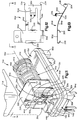
- FIG. 11-15 A fourth embodiment of the present invention is illustrated in Figs. 11-15. Since the embodiment of the invention illustrated in Figs. 11-15 is generally similar to the embodiment of the invention illustrated in Fig. 1, similar numerals are utilized to designate similar components, the suffix letter "d" being associated with the embodiment of Figs. 11-15 to avoid confusion.
- the mass 20d has a main portion 300 and first and second projection portions 302, 308 which extend from the main portion 300.
- the second projection portion 308 of the mass 20d engages the horizontal pedestal portion 16d when the mass 20d is in its unactuated position, as shown in Figs. 11 and 14.
- the first projection portion 302 of the mass 20d has a flat surface 304 which faces the tab portion 42d of the contact 40d.
- the mass 20d also has a protection tab 306 extending from the flat surface 304 of the first projection portion 302.
- the protection tab 306 prevents the cover 11d from striking the contact 40d when the cover 11d is moved into sealing engagement against the side wall 95d of the top plate portion 15d and the ledge 94d of the bottom plate portion 14d to seal and protect the deceleration sensor switch 10d.
- the first and second terminal parts 84d, 86d allow the base 12d to be mounted above a printed circuit board with space between the base 12d and the printed circuit board. Components to be mounted on the printed circuit board may be accommodated in this space between the base 12d and the printed circuit board.
- the spring 22d has a central portion 340 with a relatively small pitch. Also, each of the ends 90d, 91d of the spring 22d has a relatively small pitch. The pitch of the ends 90d, 91d and the pitch of the central portion 340 are relatively small compared to the pitch of other portions of the spring 22d.
- the mass 20d is rectangular and has a flat bottom surface (not shown) which lies parallel with a top flat surface 320 of the top plate portion 15d.
- the flat bottom surface of the rectangular mass 20d is spaced apart from the top flat surface 320 at a distance which prevents rotation of the rectangular mass 20d about the longitudinal central axis 99d of the rod portion 18d.
- the rectangular mass 20d may have a square shape.
- the end 50d of the contact 40d is welded to the terminal 30d so that the two parallel strip portions 44d of the contact 40d extend horizontally, as viewed in Fig. 11.
- a pair of lip portions 330 extend from the end 50d of the contact 40d and wrap around the terminal 30d to further secure the end 50d to the terminal 30d.
- Each of the legs 53d of the contact portion 52d has a silver nickel button 336 welded onto the free end of the leg to increase the thermal mass of the leg and thereby to increase the current carrying capacity of the leg.
- the tab portion 42d of the contact 40d has a pair of contact ears 334 which extend parallel with each other.
- the contact ears 334 have convex-shaped arcuate edge surfaces 338 which engage the flat surface 304 of the first projection portion 302 of the mass 20d when the mass 20d is in its unactuated position, as shown in Figs. 11 and 14.
- the mass 20d moves to its actuated position (not shown), the mass 20d slides along the rod portion 18d in a direction against the bias of the spring 22d to compress the spring 22d. As this occurs, the flat surface 304 on the first projection portion 302 of the mass 20d moves away from the arcuate edge surfaces 338 of the contact ears 334. This allows the spring-like force of the two parallel strip portions 44d acting on the legs 53d of the contact portion 52d to move into engagement with the surface 35d of the terminal 34d. Thus, the terminal 30d is electrically connected with the terminal 34d when the mass 20d is in its actuated position.
- the contact portion 52d of the contact 40d is spaced apart a predetermined distance from the terminal 34d. This predetermined distance is designated with the letter “D”, as shown in Fig. 14. It should be noted that the protection tab 306 (Fig. 11) extending from the flat surface 304 of the first projection portion 302 of the mass 20d is removed from Fig. 14 to clearly illustrate the engagement between the flat surface 304 and the convex-shaped arcuate edge surfaces 338 of the contact ears 334.
- the mass 20d is slidably mounted on the rod portion 18d for sliding movement along the longitudinal central axis 99d of the rod portion 18d, it is possible that the mass 20d may have some lateral play relative to the rod portion 18d.
- the mass 20d may move from the position shown in Fig. 14 to the position shown in Fig. 15, i.e., in a direction perpendicular to the longitudinal central axis 99d of the rod portion 18d.
- the position of the mass 20d is downward from the position of the mass 20d shown in Fig. 14.
- the distance the mass 20d moved from the position shown in Fig. 14 to the position shown in Fig. 15 is designated with the letter "X" in Fig. 15.
- the actual distance the mass 20d may move laterally relative to the rod portion 18d is relatively small, but is shown exaggerated in Fig. 15 for purposes of illustration.
- the flat surface 304 of the first projection portion 302 of the mass 20d wipes across the convex-shaped arcuate edge surfaces 338 of the contact ears 334.
- the convex shape of the arcuate edge surfaces 338 allows the distance between the surface 35d of the terminal 34d and the silver nickel button 336 on each of the legs 53d of the contact portion 52d of the contact 40d to be maintained at the same distance D as the flat surface 304 wipes across the arcuate edge surfaces 338 of the contact ears 334.
- the same distance D is maintained between the surface 35d of the terminal 34d and the silver nickel button 336 on each of the legs 53d of the contact portion 52d of the contact 40d when the mass 20d is in its unactuated position and the mass 20d moves in a direction perpendicular to the longitudinal central axis 99d of the rod portion 18d.
- the rectangular mass 20d is prevented from rotating about the longitudinal central axis 99d of the rod portion 18d.
- the flat surface 304 of the first projection portion 302 of the mass 20d is prevented from moving out of proper alignment relative to the arcuate edge surfaces 338 of the contact ears 334.
Landscapes
- Switches Operated By Changes In Physical Conditions (AREA)
- Push-Button Switches (AREA)
Description
- The present invention relates to a deceleration sensor switch, and is particularly directed to a deceleration sensor switch comprising an inertia mass which moves against a spring bias in response to a predetermined deceleration.
- Deceleration sensor switches which include an inertia mass which moves against a spring bias in response to a predetermined deceleration are known. One known deceleration sensor switch includes a donut-shaped inertial mass slidable on a rod against a spring bias. Another known deceleration sensor switch includes a mass disposed in a cylindrical chamber in a body and movable in the chamber against a spring bias. Also, some of the known deceleration sensor switches have means for adjusting the spring bias to adjust the responsiveness of the deceleration sensor switch.
- In accordance with one embodiment of the present invention, a deceleration sensor switch comprises a mass mounted on a rod portion and movable relative to the rod portion between an unactuated position and an actuated position along the longitudinal central axis of the rod portion. The mass moves from the unactuated position to the actuated position when the deceleration sensor switch is subjected to deceleration of a predetermined magnitude. The mass moves against a spring bias to provide a restoring force which acts on the mass to move the mass relative to the rod portion from the actuated position back to the unactuated position. The spring bias is provided by a helical coil spring helically wound around the rod portion along its longitudinal central axis.
- First and second electrical terminals are electrically connectable with each other. Connecting means is provided for electrically connecting the first and second electrical terminals with each other when the mass moves from the unactuated position to the actuated position. The connecting means comprises a contact including (i) a releasable tab portion which engages the mass when said mass is in the unactuated position and which is released for movement with the rectangular mass when the rectangular mass moves from the unactuated position to the actuated position, (ii) a biasing portion which biases the tab portion into engagement with the rectangular mass, and (iii) a contact portion which is spaced apart a predetermined distance from one of the first and second electrical terminals when the rectangular mass is in the unactuated position and which contacts the one electrical terminal when the rectangular mass is in the actuated position.
- According to a further embodiment the releasable tab portion includes means for enabling the contact portion to maintain the predetermined distance from the one electrical terminal upon movement of the rectangular mass in a direction perpendicular to the longitudinal central axis of the rod portion.
- According to still a further embodiment a plate portion of the base includes a flat surface which is parallel with one side of a rectangular mass when said rectangular mass is mounted on the rod portion. The flat surface is spaced apart from the one side of the rectangular mass at a distance which prevents rotation of the rectangular mass about the longitudinal central axis of the rod portion. Protection tab means is disposed on the rectangular mass. The protection tab means prevents a cover engageable with the base from striking the connecting means when the cover is moved towards the base to engage the base. The cover engages the base to enclose the rectangular mass and the helical coil spring.
- The foregoing and other features of the present invention will become apparent to one skilled in the art to which the present invention relates upon consideration of the following description of the invention with reference to the accompanying drawings, wherein:
- Fig. 1 is a perspective view of a deceleration sensor switch constructed in accordance with the present invention and looking at the switch at a given angle;
- Fig. 2 is another perspective view of the deceleration sensor switch of Fig. 1 and looking at the switch at a different angle;
- Fig. 3 is a sectional view, taken approximately along line 3-3 of Fig. 1 and with parts removed, showing a base of the deceleration sensor switch of Fig. 1;
- Fig. 4 is an enlarged view of a disc-shaped washer used in the deceleration sensor switch of Fig. 1;
- Fig. 5 is a plan view of a movable contact used in the deceleration sensor switch of Fig. 1;
- Fig. 6 is an enlarged view of a portion of the deceleration sensor switch of Fig. 2 as viewed in the direction along line 6-6 in Fig. 2;
- Fig. 7 is a view similar to Fig. 6 but showing parts of the deceleration sensor switch in different positions;
- Fig. 8 is a view similar to Fig. 7 but showing parts of the deceleration sensor switch in still other positions;
- Fig. 9 is a perspective view, similar to the perspective view shown in Fig. 1, of a second embodiment of the present invention;
- Fig. 10 is a perspective view, similar to the perspective view shown in Fig. 9, of a third embodiment of the present invention;
- Fig. 11 is a perspective view, similar to the perspective view shown in Fig. 1, of a fourth embodiment of the present invention;
- Fig. 12 is a plan view of a movable contact used in the deceleration sensor switch of Fig. 11;
- Fig. 13 is a view of the movable contact of Fig. 12 as viewed in the direction along line 13-13 in Fig. 12;
- Fig. 14 is an enlarged view of a portion of the deceleration sensor switch of Fig. 11 with some parts removed, as viewed in the direction along line 14-14 in Fig. 11;' and
- Fig. 15 is a view similar to Fig. 14 but showing parts of the deceleration sensor switch in different positions.
-
- The present invention is directed to a deceleration sensor switch comprising a mass which moves against a spring bias. A deceleration sensor switch in accordance with the present invention may be used in a variety of different systems. Preferably, the deceleration sensor switch is used in a vehicle occupant safety system, such as an air bag system, to trigger inflation of an air bag in the event of vehicle deceleration indicative of a vehicle collision. A
deceleration sensor switch 10 constructed in accordance with the present invention is shown in Fig. 1. - The
deceleration sensor switch 10 comprises abase 12. Thebase 12 includes abottom plate portion 14 and atop plate portion 15 located above thebottom plate portion 14. Thebottom plate portion 14 lies in a flat plane. Thetop plate portion 15 lies in another flat plane which is parallel to the flat plane in which thebottom plate portion 14 lies. Thebottom plate portion 14 has amain body part 82, a firstterminal support part 84 located adjacent one end of themain body part 82, and a secondterminal support part 86 located adjacent an opposite end of themain body part 82. The first and secondterminal support parts main body part 82. - As shown in Figs. 1 and 2, the
bottom plate portion 14 is larger than thetop plate portion 15. Thetop plate portion 15 overlies part of thebottom plate portion 14 in such a way that a ledge 94 of uniform width is formed around the outer periphery of thebase 12. Thetop plate portion 15 has aside wall 95 which extends around the outer periphery of thetop plate portion 15. Theside wall 95 extends perpendicular to theledge 94. A cover 11 (shown only in Fig. 1) is sealingly engageable against theside wall 95 of thetop plate portion 15 and theledge 94 of thebottom plate portion 14 to seal and protect thedeceleration sensor switch 10. - The
base 12 further includes ahorizontal pedestal portion 16 located above thetop plate portion 15 and avertical pedestal portion 17 located above thehorizontal pedestal portion 16. Thehorizontal pedestal portion 16 overlies part of the-top plate portion 15 and thevertical pedestal portion 17 projects perpendicularly away from thehorizontal pedestal portion 16. Thevertical pedestal portion 17 has a first vertically projectingpart 47 and a second vertically projectingpart 49 which is smaller than the first vertically projectingpart 47. A vertically extendingslot 48 is defined between the first and second vertically projectingparts vertical pedestal portion 17. - The
base 12 further includes atubular rod portion 18 spaced from thetop plate portion 15 and cantilevered from thevertical pedestal portion 17. Therod portion 18 has a free end 19 (Fig. 1) and a longitudinal central axis 99 (Fig. 2) which extends parallel to the flat planes in which the top andbottom plate portions rod portion 18, the horizontal andvertical pedestal portions bottom plate portions - A
mass 20 is mounted on therod portion 18 and is movable relative to therod portion 18 between an unactuated position shown in Fig. 6 and an actuated position shown in Fig. 8 along the longitudinalcentral axis 99 of therod portion 18. Themass 20 has a first ring-like portion 21 having a cross-sectional outer diameter and a second ring-like pilot portion 23 having a cross-sectional outer diameter smaller than the cross-sectional outer diameter of the first ring-like portion 21. The first and second ring-like portions - A
spring 22 in the form of a helical coil spring is helically wound around therod portion 18 along its longitudinalcentral axis 99. Thespring 22 has one end 90 (Fig. 2) and another end 91 (Fig. 1) located opposite the oneend 90. The second ring-like pilot portion 23 of themass 20 extends into theend 90 of thespring 22 to support and guide thespring 22. Theend 90 of thespring 22 abuts against a ring-shaped surface 97 (Fig. 6) at one end of thefirst portion 21 of themass 20. The spring bias of thespring 22 presses against the ring-shapedsurface 97 of thefirst portion 21 of the mass 20 to press themass 20 into engagement with thevertical pedestal portion 17. - As shown in Fig. 2, an
adjustable calibration member 24 in the form of a threaded screw having ahead portion 25 is screwed into thefree end 19 of therod portion 18. Therod portion 18 has a cylindrical hole 80 (shown only in Fig. 3) in which the threads of the threadedscrew 24 engage. Awasher 27 is located between thehead portion 25 of the threadedscrew 24 and thefree end 19 of therod portion 18. - As shown in enlarged detail in Fig. 4, the
washer 27 includes a ring-like pilot portion 70 and a ring-like flange portion 72 extending from the ring-like pilot portion 70. The ring-like portions like pilot portion 70 of thewasher 27 extends into the end 91 of thespring 22 to support and guide thespring 22. The end 91 of thespring 22 abuts against a ring-shaped surface 71 (Fig. 4) on the ring-like flange portion 72 of thewasher 27. The spring bias of thespring 22 presses against the ring-shapedsurface 71 of the ring-like flange portion 72 of thewasher 27 to press thewasher 27 into engagement with thehead portion 25 of the threadedscrew 24. The threadedscrew 24 is received in a hole 74 (Fig. 4) which extends through the ring-like pilot portion 70 of thewasher 27. - The threaded
screw 24 can be rotated clockwise or counterclockwise to either move thewasher 27 towards thefree end 19 of therod portion 18 or to allow thewasher 27 to move away from thefree end 19 of therod portion 18 due to the spring bias of thespring 22 acting on thewasher 27. Therefore, the position of thewasher 27 relative to thefree end 19 of therod portion 18 can be adjusted by rotating the threadedscrew 24 clockwise or counterclockwise. The spring bias of thespring 22 acting on themass 20 depends upon the position of thewasher 27 relative to thefree end 19 of therod portion 18. Thus, the spring bias of thespring 22 acting on themass 20 can be adjusted by rotating the threadedscrew 24 either clockwise or counterclockwise. - A terminal 30 made of a suitable electrical current conducting material, preferably stainless steel, is insert molded into the
horizontal pedestal portion 16, thetop plate portion 15, themain body part 82 of thebottom plate portion 14, and the firstterminal support part 84 of thebottom plate portion 14. The terminal 30 has bifurcatedleg portions 32 which extend away from the firstterminal support part 84 of thebottom plate portion 14. One of theleg portions 32 is connectable to a negative terminal of a voltage supply and the other one of theleg portions 32 is connectable to an external resistor for diagnostic purposes. The end of the terminal 30 opposite theleg portions 32 is one of a pair of electrical terminals of thedeceleration sensor switch 10. - Another terminal 34 also made of a suitable electrical current conducting material, preferably stainless steel, is insert molded into the
horizontal pedestal portion 16, thetop plate portion 15, themain body part 82 of thebottom plate portion 14, and the firstterminal support part 84 of thebottom plate 14. The terminal 34 has bifurcatedleg portions 36 which extend away from the firstterminal support part 84 of thebottom plate portion 14. One of theleg portions 36 is connectable to a positive terminal of a voltage supply and the other one of theleg portions 36 is connectable to an external resistor for diagnostic purposes. The end of the terminal 34 opposite theleg portions 36 is the other one of the pair of electrical terminals of thedeceleration sensor switch 10. - A pair of
leg portions 85 are insert molded into the secondterminal support part 86. Theleg portions 85 extend away from the secondterminal support part 86 in the same direction as theleg portions 32 of the terminal 30 and theleg portions 36 of the terminal 34 extend away from the firstterminal support part 84. The threeleg portions deceleration sensor switch 10 when thedeceleration sensor switch 10 is mounted for use. - As best shown in Figs. 1, 5 and 6, a
movable contact 40 made of stainless steel includes areleasable tab portion 42 and two generallyparallel strip portions 44 extending from thetab portion 42. Anedge 46 of thetab portion 42 extends through the vertically extendingslot 48 defined between the first and second vertically projectingparts vertical pedestal portion 17. Thecontact 40 also includes anend portion 50 which interconnects the twoparallel strip portions 44. Theend portion 50 is welded to aflat surface 31 of the terminal 30 so that the twoparallel strip portions 44 of thecontact 40 extend horizontally, as viewed in Fig. 1. The twoparallel strip portions 44 act like leaf springs to provide a spring-like force which presses theedge 46 of thetab portion 42 into contact with thefirst portion 21 of themass 20. - The
contact 40 also has acontact portion 52 which extends from thetab portion 42 and is located between the twoparallel strip portions 44, as best shown in Figs. 1, 5 and 6. Thecontact portion 52 has a pair of spring-like legs 53 (best shown in Fig. 5) which are contactable with a surface 35 (Figs. 1 and 5) of the terminal 34. When thelegs 53 of thecontact portion 52 are not contacting thesurface 35 of the terminal 34, the terminal 34 and the terminal 30 are not electrically connected. When the terminal 34 and the terminal 30 are not electrically connected, thedeceleration sensor switch 10 is in a fully opened condition, as shown in Fig. 6. When thedeceleration sensor switch 10 is in the fully opened condition shown in Fig. 6, thefirst portion 21 of themass 10 abuts against thevertical pedestal portion 17 and against theedge 46 of thetab portion 42 so as to maintain thecontact portion 52 spaced apart from thesurface 35 of the terminal 34. - When the
deceleration sensor switch 10 is subjected to deceleration of a predetermined magnitude, such as occurs in a vehicle collision, themass 20 begins to slide along therod portion 18 and in a direction against the bias ofspring 22 to compress thespring 22. As themass 20 begins to slide along therod portion 18 toward the left, as viewed in Figs. 6-8, themass 20 moves away from thevertical pedestal portion 17 and theedge 46 of thetab portion 42. - As the
mass 20 moves away from theedge 46 of thetab portion 42, thetab portion 42 is released and slides through the slot 48 (towards the left as viewed in Figs. 6-8) due to the spring-like force of the twoparallel strip portions 44 acting on thetab portion 42. Thetab portion 42 continues to slide through theslot 48 until thelegs 53 of thecontact portion 52 move into an initial contact position relative to thesurface 35 of the terminal 34, as shown in Fig. 7, to establish initial electrical connection between the terminal 34 and the terminal 30. When thelegs 53 of thecontact portion 52 are in their initial contact position shown in Fig. 7 and initial electrical connection is established between the terminal 34 and the terminal 30, thedeceleration sensor switch 10 is in an initial closed condition. - After the
legs 53 of thecontact portion 52 move into its initial contact position relative to thesurface 35 of the terminal 34, as shown in Fig. 7, themass 20 continues to move away from theedge 46 of thetab portion 42 to further compress thespring 22. As themass 20 continues to move away from theedge 46 of thetab portion 42 to further compress thespring 22, thetab portion 42 continues to slide through theslot 48 due to the spring-like force of the twoparallel strip portions 44 acting on thetab portion 42. As thetab portion 42 continues to slide through theslot 48, thelegs 53 of thecontact portion 52 wipe (slide) across thesurface 35 of the terminal 34. - The
legs 53 of thecontact portion 52 continue to wipe across thesurface 35 of the terminal 34 until they reach a final contact position, as shown in Fig. 8. When thelegs 53 of thecontact portion 52 reach the final contact position shown in Fig. 8, thetab portion 42 stops sliding through theslot 48. However, themass 20 may continue to slide farther along therod portion 18 and to move farther away from theedge 46 of thetab portion 42, as shown in Fig. 8, due to the deceleration forces acting on thedeceleration sensor switch 10. - During their wiping movement from their initial contact position shown in Fig. 7 to their final contact position shown in Fig. 8, the
legs 53 of thecontact portion 52 move a certain distance, designated with reference letter A in Fig. 8, across thesurface 35 of the terminal 34. The distance A is relatively small, but is shown exaggerated in Fig. 8 for purposes of illustration. Electrical contact between the terminal 34 and the terminal 30 is maintained during wiping movement of thelegs 53 of thecontact portion 52 from their initial contact position shown in Fig. 7 to their final contact position shown in Fig. 8. When thelegs 53 of thecontact portion 52 are in their final contact position shown in Fig. 8 and electrical contact is maintained between the terminal 34 and the terminal 30, thedeceleration sensor 10 is in a fully closed condition. - By allowing the
legs 53 of thecontact portion 52 to wipe across thesurface 35 of the terminal 34 as thelegs 53 of thecontact portion 52 move from their initial contact position shown in Fig. 7 to their final contact position shown in Fig. 8, the electrical connection between the terminal 34 and the terminal 30 is very reliable. This is because the wiping motion helps to overcome any small particles which may be present between thesurface 35 of the terminal 34 and thelegs 53 of thecontact portion 52. Also, the wiping motion results in a rubbing action between two contact areas. This rubbing action helps to penetrate through any oxides, corrosion, or other non-conducting film which may be present on the contact areas between thesurface 35 of the terminal 34 and thelegs 53 of thecontact portion 52. - The
mass 20 begins to move from its actuated position shown in Fig. 8 back toward its unactuated position shown in Fig. 6 due to the spring bias of thespring 22 when the deceleration forces which caused the movement of the mass 20 to its actuated position dissipates. As viewed in Fig. 8, themass 20 begins to move toward the right. Themass 20 continues to move toward the right until thefirst portion 21 of themass 20 comes into initial contact with theedge 46 of thetab portion 42 of thecontact 40. - After the
first portion 21 of themass 20 comes into initial contact with theedge 46 of thetab portion 42, themass 20 continues to move to the right. As this occurs, themass 20 presses against theedge 46 of thetab portion 42 to slide thetab portion 42 through the slot 48 (towards the right as viewed in Figs. 6-8). Themass 20 continues to move to the right and thetab portion 42 continues to slide through theslot 48 until thelegs 53 of thecontact portion 52 move away from thesurface 35 of the terminal 34. The mass then continues to move to the right until eventually themass 20 reaches its unactuated position shown in Fig. 6. When themass 20 reaches its unactuated position shown in Fig. 6, thetab portion 42 stops sliding through theslot 48 and thecontact portion 52 stops moving away from thesurface 35 of the terminal 34. Thedeceleration sensor switch 10 is thus returned to its fully opened condition, as shown in Fig. 6. - A second embodiment of the present invention is illustrated in Fig. 9. Since the embodiment of the invention illustrated in Fig. 9 is generally similar to the embodiment of the invention illustrated in Fig. 1, similar numerals are utilized to designate similar components, the suffix letter "a" being associated with the embodiment of Fig. 9 to avoid confusion.
- The
end 50a of the contact 40a is welded to the terminal 30a so that the twoparallel strip portions 44a of the contact 40a extend vertically, as viewed in Fig. 9. Also, in the embodiment of Fig. 9, therod 18a is generally rectangular in cross section and themass 20a is generally rectangular in cross section. Themass 20a has a rectangular-shaped central opening (not shown) which has a shape complementary to the shape of therod 18a and through which the rectangular-shapedrod 18a extends. The oneend 90a of thespring 22a is received in a cylindrical hollow (also not shown) in the mass 20a to support and guide thespring 22a. - The
mass 20a has amain portion 100 and a protrudingportion 102 which extends from themain portion 100. The protrudingportion 102 of themass 20a engages the tab portion 42a of the contact 40a when themass 20a is in its unactuated position, as shown in Fig. 9. When the protrudingportion 102 engages the tab portion 42a, as shown in Fig. 9, thelegs 53a of thecontact portion 52a of the contact 40a are spaced apart from the surface 35a of the terminal 34a. Thus, theterminal 30a is not electrically connected with the terminal 34a when themass 20a is in its unactuated position, as shown in Fig. 9. - When the mass 20a moves to its actuated position (not shown), the
mass 20a slides along therod 18a in a direction against the bias of thespring 22a to compress thespring 22a. As this occurs, the protrudingportion 102 of the mass 20a moves away from the tab portion 42a of the contact 40a. This allows the spring-like force of the twoparallel strip portions 44a acting on the tab portion 42a to move thelegs 53a of thecontact portion 52a of the contact 40a into engagement with the surface 35a of the terminal 34a. Thus, theterminal 30a is electrically connected with the terminal 34a when themass 20a is in its actuated position. - A third embodiment of the present invention is illustrated in Fig. 10. Since the embodiment of the invention illustrated in Fig. 10 is generally similar to the embodiment of the invention illustrated in Fig. 1, similar numerals are utilized to designate similar components, the suffix letter "b" being associated with the embodiment of Fig. 10 to avoid confusion.
- As shown in Fig. 10, a
contact 210 includes astem portion 212 and a pair oflegs 214 extending from thestem portion 212. Thestem portion 212 is welded to the terminal 30b. The terminal 34b has the general shape of a horseshoe having an opening 220. In the embodiment of Fig. 10, therod 18b is generally rectangular in cross section and the mass 20b is generally rectangular in cross section. The mass 20b has a rectangular-shaped central opening (not shown) which has a shape complementary to the shape of therod 18b and through which the rectangular-shapedrod 18b extends. The oneend 90b of the spring 22b is received in a cylindrical hollow (also not shown) in the mass 20b to support and guide the spring 22b. - The mass 20b has a
main portion 200 and a protrudingportion 202 which extends from themain portion 200. The protrudingportion 202 of the mass 20b extends through the opening 220 and engages thestem portion 212 when the mass 20b is in its unactuated position, as shown in Fig. 10. When the protrudingportion 202 engages thestem portion 212, as shown in Fig. 10, thelegs 214 of thecontact 210 are spaced apart from thesurface 35b of the terminal 34b. Thus, the terminal 30b is not electrically connected with the terminal 34b when the mass 20b is in its unactuated position, as shown in Fig. 10. - When the mass 20b moves to its actuated position (not shown), the mass 20b slides along the
rod 18b in a direction against the bias of the spring 22b to compress the spring 22b. As this occurs, the protrudingportion 202 of the mass 20b moves away from thestem portion 212 of thecontact 210. This allows the spring-like force of thestem portion 212 acting on thelegs 214 to move thelegs 214 into engagement with thesurface 35b of the terminal 34b. Thus, the terminal 30b is electrically connected with the terminal 34b when the mass 20b is in its actuated position. - A fourth embodiment of the present invention is illustrated in Figs. 11-15. Since the embodiment of the invention illustrated in Figs. 11-15 is generally similar to the embodiment of the invention illustrated in Fig. 1, similar numerals are utilized to designate similar components, the suffix letter "d" being associated with the embodiment of Figs. 11-15 to avoid confusion.
- As shown in Fig. 11, the
mass 20d has amain portion 300 and first andsecond projection portions main portion 300. Thesecond projection portion 308 of themass 20d engages thehorizontal pedestal portion 16d when themass 20d is in its unactuated position, as shown in Figs. 11 and 14. Thefirst projection portion 302 of themass 20d has aflat surface 304 which faces thetab portion 42d of thecontact 40d. Themass 20d also has aprotection tab 306 extending from theflat surface 304 of thefirst projection portion 302. Theprotection tab 306 prevents thecover 11d from striking thecontact 40d when thecover 11d is moved into sealing engagement against theside wall 95d of thetop plate portion 15d and theledge 94d of thebottom plate portion 14d to seal and protect thedeceleration sensor switch 10d. - The first and second
terminal parts base 12d to be mounted above a printed circuit board with space between thebase 12d and the printed circuit board. Components to be mounted on the printed circuit board may be accommodated in this space between thebase 12d and the printed circuit board. - As shown in Fig. 11, the
spring 22d has acentral portion 340 with a relatively small pitch. Also, each of theends spring 22d has a relatively small pitch. The pitch of theends central portion 340 are relatively small compared to the pitch of other portions of thespring 22d. - The
mass 20d is rectangular and has a flat bottom surface (not shown) which lies parallel with a topflat surface 320 of thetop plate portion 15d. The flat bottom surface of therectangular mass 20d is spaced apart from the topflat surface 320 at a distance which prevents rotation of therectangular mass 20d about the longitudinalcentral axis 99d of therod portion 18d. Therectangular mass 20d may have a square shape. - Referring to Figs. 11-14, the
end 50d of thecontact 40d is welded to the terminal 30d so that the twoparallel strip portions 44d of thecontact 40d extend horizontally, as viewed in Fig. 11. A pair oflip portions 330 extend from theend 50d of thecontact 40d and wrap around the terminal 30d to further secure theend 50d to the terminal 30d. Each of thelegs 53d of thecontact portion 52d has asilver nickel button 336 welded onto the free end of the leg to increase the thermal mass of the leg and thereby to increase the current carrying capacity of the leg. Thetab portion 42d of thecontact 40d has a pair ofcontact ears 334 which extend parallel with each other. Thecontact ears 334 have convex-shaped arcuate edge surfaces 338 which engage theflat surface 304 of thefirst projection portion 302 of the mass 20d when themass 20d is in its unactuated position, as shown in Figs. 11 and 14. - When the mass 20d moves to its actuated position (not shown), the
mass 20d slides along therod portion 18d in a direction against the bias of thespring 22d to compress thespring 22d. As this occurs, theflat surface 304 on thefirst projection portion 302 of the mass 20d moves away from the arcuate edge surfaces 338 of thecontact ears 334. This allows the spring-like force of the twoparallel strip portions 44d acting on thelegs 53d of thecontact portion 52d to move into engagement with thesurface 35d of the terminal 34d. Thus, theterminal 30d is electrically connected with the terminal 34d when themass 20d is in its actuated position. - When the
mass 20d is in its unactuated position as shown in Fig. 14, thecontact portion 52d of thecontact 40d is spaced apart a predetermined distance from the terminal 34d. This predetermined distance is designated with the letter "D", as shown in Fig. 14. It should be noted that the protection tab 306 (Fig. 11) extending from theflat surface 304 of thefirst projection portion 302 of themass 20d is removed from Fig. 14 to clearly illustrate the engagement between theflat surface 304 and the convex-shaped arcuate edge surfaces 338 of thecontact ears 334. - Although the
mass 20d is slidably mounted on therod portion 18d for sliding movement along the longitudinalcentral axis 99d of therod portion 18d, it is possible that themass 20d may have some lateral play relative to therod portion 18d. For example, themass 20d may move from the position shown in Fig. 14 to the position shown in Fig. 15, i.e., in a direction perpendicular to the longitudinalcentral axis 99d of therod portion 18d. As viewed in Fig. 15, the position of themass 20d is downward from the position of themass 20d shown in Fig. 14. The distance themass 20d moved from the position shown in Fig. 14 to the position shown in Fig. 15 is designated with the letter "X" in Fig. 15. The actual distance themass 20d may move laterally relative to therod portion 18d is relatively small, but is shown exaggerated in Fig. 15 for purposes of illustration. - When the mass 20d moves from the position shown in Fig. 14 to the position shown in Fig. 15, the
flat surface 304 of thefirst projection portion 302 of the mass 20d wipes across the convex-shaped arcuate edge surfaces 338 of thecontact ears 334. The convex shape of the arcuate edge surfaces 338 allows the distance between thesurface 35d of the terminal 34d and thesilver nickel button 336 on each of thelegs 53d of thecontact portion 52d of thecontact 40d to be maintained at the same distance D as theflat surface 304 wipes across the arcuate edge surfaces 338 of thecontact ears 334. Thus, the same distance D is maintained between thesurface 35d of the terminal 34d and thesilver nickel button 336 on each of thelegs 53d of thecontact portion 52d of thecontact 40d when themass 20d is in its unactuated position and the mass 20d moves in a direction perpendicular to the longitudinalcentral axis 99d of therod portion 18d. - As previously mentioned, the
rectangular mass 20d is prevented from rotating about the longitudinalcentral axis 99d of therod portion 18d. By preventing therectangular mass 20d from rotating about the longitudinalcentral axis 99d of therod portion 18d, theflat surface 304 of thefirst projection portion 302 of themass 20d is prevented from moving out of proper alignment relative to the arcuate edge surfaces 338 of thecontact ears 334.
Claims (12)
- A deceleration sensor switch (10) comprising:characterized in that said connecting contact comprises a contact (40d) including (i) a releasable tab portion which engages said mass (20d) when said mass is in said unactuated position and which is released for movement with said mass when said mass moves from said unactuated position to said actuated position, (ii) a biasing portion (44d) which biases said tab portion into engagement with said mass, and (iii) a contact portion (52d) which is spaced apart a predetermined distance (D) from one of said first and second electrical terminals (34d) when said mass is in said unactuated position and which contacts said one electrical terminal when said mass is in said actuated position.a mass (20) mounted on a rod portion (18) and movable relative to said rod portion between an unactuated position and an actuated position along the longitudinal central axis of said rod portion, said mass (20) moving from said unactuated position to said actuated position when said mass is subjected to deceleration of a predetermined magnitude;spring means (22) for providing a restoring force which acts on said mass (20) to move said mass relative to said rod portion from said actuated position back to said unactuated position after said mass has moved to said actuated position;a first electrical terminal (30) and a second electrical terminal (34) electrically connectable with said first electrical terminal;a connecting contact (40) for electrically connecting said first and second electrical terminals (30, 34) with each other when said mass (20) moves from said unactuated position to said actuated position; andsaid first and second electrical terminals (30, 34) extending generally perpendicular to said flat plane and through said base (12).
- A deceleration sensor switch according to claim 1 wherein said releasable tab portion includes means (334, 338) for enabling said contact portion (52d) to maintain said predetermined distance (D) from said one electrical terminal (34d) upon movement of said mass in a direction perpendicular to the longitudinal central axis (99) of said rod portion.
- A deceleration sensor switch (10) according to claim 1 or 2 comprising a base (12) including a plate portion (15), a vertical pedestal portion (16, 17) projecting from said plate portion, and a rod portion (18) spaced from said plate portion and cantilivered from said pedestal portion, said plate portion (15) lying in a flat plane and said rod portion (18) having a longitudinal central axis (99) parallel to the flat plane, and a cover (11) defining a chamber in which said rod portion and said mass are located, said cover (11) having a portion engageable with said base (12) and, when engaged with the base, enclosing said mass and said spring means and providing a sealed chamber.
- A deceleration sensor switch according to claims 1 or 2 wherein said mass (20d) includes a projection portion (302) having an edge surface against which said releasable tab portion engages when said mass is in said unactuated position.
- A deceleration sensor switch according to claims 2 or 3 wherein said enabling means includes an arcuate edge surface (338) which engages said edge surface of said projection portion (302) of said mass when said mass is in said unactuated position, said arcuate edge surface (338) having a convex shape relative to said edge surface of said projection portion of said mass.
- A deceleration sensor switch according to any of claims 1-5 wherein said mass (20a, 20b, 20d) is rectangular and said base includes a flat surface which is parallel with one side of said rectangular mass when said rectangular mass is mounted on said rod portion, said flat surface being spaced apart from said one side of said rectangular mass at a distance which prevents rotation of said rectangular mass about the longitudinal central axis of said rod portion.
- A deceleration sensor switch according to claim 6 wherein said rectangular mass (20a, 20b, 20d) has a square shape.
- A deceleration sensor switch according to any of claims 1-7 further including protection tab means (306) disposed on said mass (20d) and for preventing said cover (11d) from striking said connecting means when said cover is moved towards said base to engage said base.
- A deceleration sensor switch according to claim 2 wherein said plate, pedestal, and rod portions comprise a single continuous piece of plastic molded material.
- A deceleration sensor switch according to claim 9 further comprising means (24, 27) disposed at one end of said rod portion (18) and for enabling adjustment of the restoring force of said spring means (22) acting on said mass (20).
- A deceleration sensor switch according to claim 10 wherein said mass (20) is mounted at an opposite end of said rod portion.
- A deceleration sensor switch according to any of claims 1-11 wherein said rod portion (18) is tubular and further including calibration means (24) disposed at one end of said tubular rod portion and for enabling adjustment of the restoring force of said spring means (22) acting on said mass (20), said calibration means including an adjustable calibration screw (24) which can be rotated clockwise or counterclockwise to adjust the restoring force of said spring means acting on said mass.
Applications Claiming Priority (2)
| Application Number | Priority Date | Filing Date | Title |
|---|---|---|---|
| US08/036,482 US5306883A (en) | 1993-03-24 | 1993-03-24 | Deceleration sensor switch for use in a vehicle occupant safety system |
| US36482 | 1993-03-24 |
Publications (2)
| Publication Number | Publication Date |
|---|---|
| EP0617444A1 EP0617444A1 (en) | 1994-09-28 |
| EP0617444B1 true EP0617444B1 (en) | 1999-12-22 |
Family
ID=21888833
Family Applications (1)
| Application Number | Title | Priority Date | Filing Date |
|---|---|---|---|
| EP94104621A Expired - Lifetime EP0617444B1 (en) | 1993-03-24 | 1994-03-23 | Deceleration sensor switch for use in a vehicle occupant safety system |
Country Status (5)
| Country | Link |
|---|---|
| US (2) | US5306883A (en) |
| EP (1) | EP0617444B1 (en) |
| JP (1) | JP2898193B2 (en) |
| KR (1) | KR0145263B1 (en) |
| DE (1) | DE69422211T2 (en) |
Families Citing this family (13)
| Publication number | Priority date | Publication date | Assignee | Title |
|---|---|---|---|---|
| JP2867843B2 (en) * | 1993-07-01 | 1999-03-10 | 株式会社デンソー | Collision detection device |
| US5393944A (en) * | 1994-05-16 | 1995-02-28 | Trw Technar Inc. | Deceleration switch with a switch base supporting a flexible oscillating one piece plastic mass unit |
| US5424501A (en) * | 1994-05-16 | 1995-06-13 | Trw Technar Inc. | Deceleration sensor switch for use in a vehicle occupant safety system |
| JPH08189935A (en) * | 1995-01-10 | 1996-07-23 | Mitsubishi Electric Corp | Collision detector |
| JPH0920205A (en) * | 1995-07-07 | 1997-01-21 | Mitsubishi Electric Corp | Occupant protection device and its activation device |
| JPH0982190A (en) * | 1995-09-08 | 1997-03-28 | Mitsubishi Electric Corp | Collision detection device and manufacturing method thereof |
| JP3351218B2 (en) * | 1996-01-31 | 2002-11-25 | 三菱電機株式会社 | Acceleration detector |
| US5695242A (en) * | 1996-02-15 | 1997-12-09 | Breed Automotive Technology, Inc. | Seat cushion restraint system |
| US5844164A (en) * | 1996-02-23 | 1998-12-01 | Breed Automotive Technologies, Inc. | Gas generating device with specific composition |
| US5684336A (en) * | 1996-03-04 | 1997-11-04 | Trw Inc. | Crash sensor assembly including both an inertia sensor and an accelerometer and method |
| US5789716A (en) * | 1996-11-12 | 1998-08-04 | Wang; Pi-Lin | One-way shaking switch |
| JP7053629B2 (en) * | 2017-01-06 | 2022-04-12 | バイエル クロップサイエンス エルピー | Sensor for wireless animal catcher detection system |
| CN112985655B (en) * | 2021-02-23 | 2023-06-09 | 富延升电子(福建)有限公司 | Pressure sensor capable of automatically recovering based on intelligent manufacturing |
Family Cites Families (21)
| Publication number | Priority date | Publication date | Assignee | Title |
|---|---|---|---|---|
| US2984719A (en) * | 1953-08-20 | 1961-05-16 | Paul M Higgs | Shock and pressure sensitive switch |
| US3549169A (en) * | 1966-07-01 | 1970-12-22 | Eaton Yale & Towne | Inflatable safety device |
| US3571539A (en) * | 1968-08-20 | 1971-03-23 | Eaton Yale & Towne | Collision sensor |
| DE2058743A1 (en) * | 1970-11-30 | 1972-06-08 | Dynamit Nobel Ag | Electric switch |
| US3662606A (en) * | 1971-01-21 | 1972-05-16 | Gen Motors Corp | Acceleration sensor |
| US3832507A (en) * | 1971-10-22 | 1974-08-27 | Gen Motors Corp | Sensor switch for occupant restraint system with spring fracture detection means |
| JPS5222731Y2 (en) * | 1972-03-31 | 1977-05-25 | ||
| FR2188167A1 (en) * | 1972-06-13 | 1974-01-18 | Sedc | |
| JPS5331406Y2 (en) * | 1973-11-28 | 1978-08-04 | ||
| JPS545578A (en) * | 1977-06-15 | 1979-01-17 | Nippon Denso Co | Device for detecting collision |
| JPS54121783A (en) * | 1978-03-14 | 1979-09-21 | Susumu Ubukata | Vibration sensor |
| JPH0658781B2 (en) * | 1982-01-27 | 1994-08-03 | 株式会社日立製作所 | Collision speed detector |
| JPH0120751Y2 (en) * | 1984-12-05 | 1989-06-22 | ||
| US5053588A (en) * | 1990-02-20 | 1991-10-01 | Trw Technar Inc. | Calibratable crash sensor |
| US5066837A (en) * | 1990-03-09 | 1991-11-19 | Trw Technar Inc. | Gas damped deceleration switch |
| US5153393A (en) * | 1990-03-22 | 1992-10-06 | David S. Breed | Crash sensor for a passive motor vehicle occupant restraint system |
| JPH042439U (en) * | 1990-04-16 | 1992-01-10 | ||
| KR950011297B1 (en) * | 1990-07-16 | 1995-09-30 | 센서 테크놀로지 가부시까기이샤 | A collision sensor |
| DE4126626C2 (en) * | 1990-08-15 | 1994-08-04 | United Distillers Plc | Marked material body and method for its production |
| JP3191331B2 (en) * | 1991-07-31 | 2001-07-23 | 株式会社デンソー | Vehicle collision detector |
| JP3033931U (en) * | 1996-07-23 | 1997-02-07 | 株式会社バンクエンジニアリング | Partition for moving in tunnel |
-
1993
- 1993-03-24 US US08/036,482 patent/US5306883A/en not_active Expired - Lifetime
- 1993-12-21 US US08/171,024 patent/US5373126A/en not_active Expired - Fee Related
-
1994
- 1994-03-23 DE DE69422211T patent/DE69422211T2/en not_active Expired - Fee Related
- 1994-03-23 EP EP94104621A patent/EP0617444B1/en not_active Expired - Lifetime
- 1994-03-23 KR KR1019940005817A patent/KR0145263B1/en not_active Expired - Fee Related
- 1994-03-24 JP JP6053994A patent/JP2898193B2/en not_active Expired - Lifetime
Also Published As
| Publication number | Publication date |
|---|---|
| KR0145263B1 (en) | 1998-08-17 |
| DE69422211T2 (en) | 2000-07-27 |
| DE69422211D1 (en) | 2000-01-27 |
| JP2898193B2 (en) | 1999-05-31 |
| JPH0773788A (en) | 1995-03-17 |
| KR940022615A (en) | 1994-10-21 |
| US5373126A (en) | 1994-12-13 |
| EP0617444A1 (en) | 1994-09-28 |
| US5306883A (en) | 1994-04-26 |
Similar Documents
| Publication | Publication Date | Title |
|---|---|---|
| US5373126A (en) | Deceleration sensor switch for use in a vehicle occupant safety system | |
| US4459440A (en) | Joystick and switch assembly therefor | |
| US3553402A (en) | Pressure switch with improved diaphragm and snap action disc structure | |
| CA2135337C (en) | Detented rocker switch | |
| CA2102392C (en) | Push-button switches | |
| CA2056462C (en) | In field settable differential pressure switch assembly for low fluid pressure applications | |
| US5393944A (en) | Deceleration switch with a switch base supporting a flexible oscillating one piece plastic mass unit | |
| US4590344A (en) | Machine insertable DIP switch | |
| US4767896A (en) | Stamped circuitry assembly | |
| US5122627A (en) | Asymmetrical electrical switch actuator | |
| US4659157A (en) | Stamped circuitry assembly | |
| CA2194644C (en) | Probe type tester with circuit board stabilizer | |
| US5424501A (en) | Deceleration sensor switch for use in a vehicle occupant safety system | |
| US4048455A (en) | Pressure switch with plural axes pivoted conduction plate | |
| US4342885A (en) | Limit switch | |
| US3636288A (en) | Pressure responsive switch with differential and range adjusting means including a differential nut | |
| US4783671A (en) | Film information reading device for camera | |
| US5013266A (en) | Twisted terminal for switching device | |
| US3819891A (en) | Push button switch | |
| US3654410A (en) | Pivoted inertia switch self-orienting along a line of deceleration in a prescribed angular pattern | |
| US4950847A (en) | Sealed printed circuit board switch | |
| EP0727795A2 (en) | Sequence switch with forced disconnect mechanism | |
| SU1558667A1 (en) | Arrangement for protecting robot | |
| GB2196793A (en) | Snap acting switches | |
| US4728759A (en) | Stamped circuitry and adjustable rotary switch assembly |
Legal Events
| Date | Code | Title | Description |
|---|---|---|---|
| PUAI | Public reference made under article 153(3) epc to a published international application that has entered the european phase |
Free format text: ORIGINAL CODE: 0009012 |
|
| AK | Designated contracting states |
Kind code of ref document: A1 Designated state(s): DE FR GB IT |
|
| 17P | Request for examination filed |
Effective date: 19941230 |
|
| 17Q | First examination report despatched |
Effective date: 19951227 |
|
| GRAG | Despatch of communication of intention to grant |
Free format text: ORIGINAL CODE: EPIDOS AGRA |
|
| GRAG | Despatch of communication of intention to grant |
Free format text: ORIGINAL CODE: EPIDOS AGRA |
|
| GRAH | Despatch of communication of intention to grant a patent |
Free format text: ORIGINAL CODE: EPIDOS IGRA |
|
| GRAH | Despatch of communication of intention to grant a patent |
Free format text: ORIGINAL CODE: EPIDOS IGRA |
|
| GRAA | (expected) grant |
Free format text: ORIGINAL CODE: 0009210 |
|
| AK | Designated contracting states |
Kind code of ref document: B1 Designated state(s): DE FR GB IT |
|
| REF | Corresponds to: |
Ref document number: 69422211 Country of ref document: DE Date of ref document: 20000127 |
|
| ITF | It: translation for a ep patent filed | ||
| ET | Fr: translation filed | ||
| PLBE | No opposition filed within time limit |
Free format text: ORIGINAL CODE: 0009261 |
|
| STAA | Information on the status of an ep patent application or granted ep patent |
Free format text: STATUS: NO OPPOSITION FILED WITHIN TIME LIMIT |
|
| 26N | No opposition filed | ||
| REG | Reference to a national code |
Ref country code: GB Ref legal event code: IF02 |
|
| PGFP | Annual fee paid to national office [announced via postgrant information from national office to epo] |
Ref country code: GB Payment date: 20020205 Year of fee payment: 9 |
|
| PGFP | Annual fee paid to national office [announced via postgrant information from national office to epo] |
Ref country code: FR Payment date: 20020228 Year of fee payment: 9 |
|
| PGFP | Annual fee paid to national office [announced via postgrant information from national office to epo] |
Ref country code: DE Payment date: 20020327 Year of fee payment: 9 |
|
| PG25 | Lapsed in a contracting state [announced via postgrant information from national office to epo] |
Ref country code: GB Free format text: LAPSE BECAUSE OF NON-PAYMENT OF DUE FEES Effective date: 20030323 |
|
| PG25 | Lapsed in a contracting state [announced via postgrant information from national office to epo] |
Ref country code: DE Free format text: LAPSE BECAUSE OF NON-PAYMENT OF DUE FEES Effective date: 20031001 |
|
| GBPC | Gb: european patent ceased through non-payment of renewal fee |
Effective date: 20030323 |
|
| PG25 | Lapsed in a contracting state [announced via postgrant information from national office to epo] |
Ref country code: FR Free format text: LAPSE BECAUSE OF NON-PAYMENT OF DUE FEES Effective date: 20031127 |
|
| REG | Reference to a national code |
Ref country code: FR Ref legal event code: ST |
|
| PG25 | Lapsed in a contracting state [announced via postgrant information from national office to epo] |
Ref country code: IT Free format text: LAPSE BECAUSE OF NON-PAYMENT OF DUE FEES;WARNING: LAPSES OF ITALIAN PATENTS WITH EFFECTIVE DATE BEFORE 2007 MAY HAVE OCCURRED AT ANY TIME BEFORE 2007. THE CORRECT EFFECTIVE DATE MAY BE DIFFERENT FROM THE ONE RECORDED. Effective date: 20050323 |