EP0617225A1 - Method and apparatus for safety monitoring of safety devices for machines - Google Patents
Method and apparatus for safety monitoring of safety devices for machines Download PDFInfo
- Publication number
- EP0617225A1 EP0617225A1 EP94104030A EP94104030A EP0617225A1 EP 0617225 A1 EP0617225 A1 EP 0617225A1 EP 94104030 A EP94104030 A EP 94104030A EP 94104030 A EP94104030 A EP 94104030A EP 0617225 A1 EP0617225 A1 EP 0617225A1
- Authority
- EP
- European Patent Office
- Prior art keywords
- signal
- static
- standstill
- safety
- switch
- Prior art date
- Legal status (The legal status is an assumption and is not a legal conclusion. Google has not performed a legal analysis and makes no representation as to the accuracy of the status listed.)
- Withdrawn
Links
Images


Classifications
-
- F—MECHANICAL ENGINEERING; LIGHTING; HEATING; WEAPONS; BLASTING
- F16—ENGINEERING ELEMENTS AND UNITS; GENERAL MEASURES FOR PRODUCING AND MAINTAINING EFFECTIVE FUNCTIONING OF MACHINES OR INSTALLATIONS; THERMAL INSULATION IN GENERAL
- F16P—SAFETY DEVICES IN GENERAL; SAFETY DEVICES FOR PRESSES
- F16P3/00—Safety devices acting in conjunction with the control or operation of a machine; Control arrangements requiring the simultaneous use of two or more parts of the body
- F16P3/08—Safety devices acting in conjunction with the control or operation of a machine; Control arrangements requiring the simultaneous use of two or more parts of the body in connection with the locking of doors, covers, guards, or like members giving access to moving machine parts
-
- G—PHYSICS
- G05—CONTROLLING; REGULATING
- G05B—CONTROL OR REGULATING SYSTEMS IN GENERAL; FUNCTIONAL ELEMENTS OF SUCH SYSTEMS; MONITORING OR TESTING ARRANGEMENTS FOR SUCH SYSTEMS OR ELEMENTS
- G05B9/00—Safety arrangements
- G05B9/02—Safety arrangements electric
- G05B9/03—Safety arrangements electric with multiple-channel loop, i.e. redundant control systems
Definitions
- the invention is based on a safety monitoring method for protective devices according to the preamble of claim 1 or a device for carrying out the method on protective devices according to the preamble of claim 6.
- This publication deals with the use of so-called safety relay modules, which can be used to achieve compact wiring-saving solutions and which can also be used in the field of protective door monitoring and guard locking for machines.
- Such monitoring circuits or tumblers of protective doors usually serve to protect people from accidents through automatic movement sequences in machines, systems and also industrial robots performing certain movement sequences.
- safety circuits for locking or unlocking doors or protective hoods can also be used increasingly in machine protection itself against undesired interruptions in automatic processes.
- a distinction can be made between a large number of circuits, for example the use of two mutually operating monitoring switches, two parallel monitoring switches and versions with or without locking (or guard locking).
- Such door locks exist in a spring pressure or magnetic force locked version.
- the safety circuit described in DE-OS 39 00 733 relates to a monitoring circuit in a modular structure which, by adding additional monitoring circuits, also relates to machines with a plurality of axes each carrying out rotary movements.
- the invention is based on the task of simplifying the control circuit and in particular while maintaining the increased security by redundantly querying machine movements or downtimes to make it more universal in its use.
- EP 0 501 218 A2 has at least already indicated that different movement or standstill signals should be evaluated for monitoring the movement or standstill of each axis circle, in that a first signal is obtained as a dynamic signal by means of suitable encoders by using a proximity switch as the motion sensor, which detects the passage of a predetermined number of teeth per unit of time depending on the speed, while a so-called static standstill signal is derived in any way, for example from the regulation of the machine to be monitored itself, to the extent that it can be referred to as a software-controlled L signal. With the help of such a redundant, because two-channel rotary motion evaluation, reliable standstill detection is guaranteed. In this context, however, difficulties can arise to the extent that not every drive system can provide the required L signal under software control from its own control system, for example because the drive control system is not suitable for the respective machine or there is no control system at all.
- the invention achieves the stated object in a generic method or in the corresponding device with the features of claim 1 or subclaim 6 and has the advantage that for any drives and in particular for those electric motors which themselves or their control or Control circuit are not able to provide static rotary motion or standstill signals without an adjustment to the correspondingly changed conditions can be made by simply setting from the outside. This is particularly important in the case of such electric drives, which are referred to as so-called hardware-controlled motors, which, for example, are supplied with their drive energy or are switched off via only contactor control.
- the invention succeeds in evaluating the switching contact of an additional contact pair on the switch-on protection in order to generate the static L signal, which the redundant safety circuit absolutely requires for the two-channel rotary motion evaluation, even if an overrun occurs during switch-off, which is necessary for immediate reaction of the contact available to the L signal generates a correspondingly differing signal for dynamic speed inquiry.
- the invention is also able to provide a redundant, because two-channel, rotary motion evaluation, even in the case of such drives, if no separate switching movement is possible or can be evaluated for obtaining the static signal.
- two dynamic sensors are arranged and a frequency-dependent switch is assigned to one of these sensors by changing the module configuration on the device in such a way that a static L signal corresponding to the dynamic signal is also generated in this case.
- this second L signal which is important for redundancy, is generated as a static signal with the aid of a frequency-dependent switch and is then routed internally to the connection terminal for the static L signal.
- both dynamic movement-dependent signals are generated by two independent proximity switches, it being possible for a toothed disk or something similar to be provided together.
- a safety relay combination area is provided which, in conjunction with door position switches and magnetic state contacts, finally switches an enabling path for controlling the motor via a contactor or the like.
- Safety relays are only activated when the monitored drive is at a standstill, the required redundant evaluation being achieved by the internal series connection of work contacts.
- the second digital switch which uses a plug-in module to generate the static L-signal, while with a constant run-down time of the drive (e.g. controlled by electronic braking devices ) the post-delayed L-signal control is possible using a hardware-controlled L-signal, the then necessary but known time delay can then be determined on an external plug-in module.
- FIGS. 2 and 3 schematically show, to the right of the target system (electric motor of a drive unit), the front view of a safety monitoring device 10, which (among other components) contains an EBUV control circuit, as its basic structure for performing redundant axis circuit monitoring, in particular in DE 38 37 218 C2 is explained in the basic principle.
- the safety monitoring device 10 contains two mutually independent monitoring systems for redundant signal evaluation, which means that rotational movement information of a respective target system must be made available in two channels independently of one another.
- a first rotary motion or standstill signal is obtained by dynamic signal control by means of scanning, for example by means of a toothed disk 11 coupled to the drive via a sensor 12 (proximity switch) which transmits a digital signal generated in proportion to the motion dynamic monitoring channel INA of the control circuit EBUV.
- a sensor 12 proximity switch
- the invention In addition to the evaluation of a software-controlled L signal from the control environment of the target system, the invention also manages the two other circumstances mentioned, different module connectors MT and MD being provided (see FIGS. 2 and 3), by which the Type of L signal control can be selected.
- the safety monitoring device also comprises a safety relay combination circuit 13, as is shown in FIG. 1 by way of example for the case of a hardware-controlled drive motor of the target system, in order to secure the mechanical protective device of the respective machine.
- a safety relay combination circuit 13 includes, for example, a protective hood lock in the axle drive area in the simplest case, or a protective door that is subject to operation of the area of the machine that is subject to movements or rotary movements, from the environment and therefore also from the operating personnel or, under certain circumstances, also entire space areas that are locked by doors for safety.
- the circuit or current path 1 contains the control contactor K for controlling the motor M, which is in series with an ON button 15 for switching on the contactor K for the motor M. In parallel with the ON button 15 there is a self-holding contact k1 of the motor contactor K, as is usual with such a configuration. This is followed in series by an OFF switch 16 and an enable switch 17, which is closed by the electronics EBUV when certain safety conditions exist, and finally an emergency-OFF switch 18.
- the supply current path 11 for the drive motor contains only one make contact -Relay contact k2 of the motor contactor K.
- the current path 111 represents a preparatory signal path for the electronics or control circuit EBUV and is connected to its input terminal KI2;
- the protective device 19 when the protective device 19 is open (for example a protective hood, door or the like), closed switching contacts 19a and 19b are in series with a normally open contact 20 of a locking magnet D (in the circuit V), the locking magnet D also simultaneously with this switching contact 20 another mechanical locking arrangement, such as a shift rod 21, a bolt, a locking member or another part moves, which belongs mechanically in the area of the protective device or door 19 and in the "activated” state prevents the door from opening and in the "unlocked” state Access to the moving parts of the redundant safety-monitored machine.
- the safety circuit IV which contains normally open contacts 19a ', 19b' of the protective device connected to the preparatory circuit, which requires an energization, i.e. a 1 signal at terminal 2, in preparation for releasing the start-up by the EBUV, contains the normally open contacts 19a ', 19b' of the protective device, which at Moving the protective device into the closed state also closes and a further locking magnet switch contact 22 as a break contact.
- the circuit V is used to switch the locking magnet D and, in series with the locking magnet D, contains an unlocking button 23, which closes when actuated, in parallel with a switching contact 24 controlled by the electronics EBUV (terminal B2 / KI. B3).
- a locking button 25 which opens when actuated
- a standstill switch contact 26 switched by the EBUV which is closed when both rotary motion sensors or standstill sensors signal the standstill of the system to be monitored, i.e. when there is movement opens and also includes separately led out terminals KI13 and KI14 on the front surface of the safety monitoring device 10, so that the standstill signal occurring at these terminals KI13 and KI14 can also be used for other purposes.
- the EBUV In order to enable (renewed) commissioning, the EBUV first determines by evaluating the inputs INA (dynamic signal) and L (static signal) that the target system has come to a standstill, whereupon the standstill switch 26 from the EBUV is closed (KI13 / KI14) so that when the switch 24 (KI B2 / KI B3) is kept closed by the EBUV, the locking magnet D is activated parallel to the unlocking button 23. The locking magnet D then closes its contact switch 20 and at the same time brings its locking rod 21 (or any other locking or locking arrangement) into the unlocked state for the door 19, which is in the position shown in the open state when the door switches 19a, 19b are closed. This results in a preparatory activation of the preparatory current path 111 and the signal resulting at input terminal KI2 of the EBUV serves as the first preparatory safety signal for the release of the drive energy connection.
- INA dynamic signal
- L static signal
- the operator can now close the ON button 15; the motor contactor K picks up, keeps the circuit closed even after the later opening of the ON button 15 via its self-holding contact k1 and the machine starts up.
- the work contact is opened according to the standstill switch 26 (KI13 / KI14) via the drive movement recognized by the EBUV (standstill detection). Unlocking is reliably prevented by this measure.
- the EBUV in order to switch their EBUV contacts (release switch 17 or standstill switch 26), the EBUV needs a static signal that can be evaluated in the same way in addition to the dynamic signal at the INA input from the proximity switch 12 (see FIG. 3)
- the creation of rotary motion from the work contact k3 mentioned above (again drawn in FIG. 3) of the drive motor contactor K is fed as a DC voltage signal to the static monitoring channel in accordance with input terminal L.
- This discrepancy is interpreted by the EBUV as a fault (the two rotational movement or standstill detection signals which ensure the redundancy no longer match), which means that the EBUV changes internally to a locked state and the standstill switch contact 26 no longer closes with no external signal combination.
- the output connection Out can also be implemented, for example, via a large light display. Acknowledgment is only possible by switching off the entire system and restarting it, as otherwise the protective device (door 19) can no longer be opened.
- the invention therefore provides that when the drive is switched off, the static signal is stored beyond the time of the switch-off for the period T3-T1 according to FIG. 5, which means in other words that for an adjustable period of time (depending on the mass of the drive or other factors influencing a caster of movement) the L signal compared to the EBUV is virtually maintained, so to speak, according to the curve profile a at time T1 at time T3, which corresponds to the adjustable internal L signal storage time.
- a module plug MT which can be connected to the device of the safety monitoring device from the outside, see FIG. Fig. 3, in which the module connector MT is drawn out at the bottom left and also indicates that, for example, a follow-up time period between 1 second and 30 seconds can be set. This option is sufficient in most cases because constant braking after-running times result from appropriate braking devices.
- the safety monitoring device is so universally applicable in the area of its control circuit that even if neither a software-derived L-signal nor a hardware-derived L-signal are available, with the help of a further module MD ( Fig. 2) the redundant two-channel system can be maintained by using a second dynamic sensor 12 'which feeds a speed-dependent frequency signal to the INB input, this signal being internal to the device using a modified external plug-in circuit by the module connector MD (cf. 2) is converted into a static L signal by means of a frequency-dependent switch.
- the standstill message is obtained via the work contact switch 26 (KI13 / KI14) precisely in coordination with the movement and the movement of the monitored system.
- the protective device therefore signals the following states via relevant contact control: Safety protective device open - interlock deactivated
- Safety protection device closed - interlock activated.
- the unit contains two independent monitoring systems.
- the standstill and rotary motion detection is used for the safe standstill message.
- the safety relay combination is required to evaluate the door position switches and the magnetic status contacts.
- Both systems are supplied together via an operating voltage connection and can meet the requirements of increased safety when connected externally.
- the unit contains a two-channel axis circle. Each channel has its own standstill and rotary motion detection (RAA / RAB) and is defined via its own independent parameters (quartz).
- the standstill and rotary motion detection (RAA / RAB) as provided via the safety output relays by the contact systems (terminal ⁇ 13/14>).
- the contact systems terminal ⁇ 13/14>.
- a dynamic signal (terminal ⁇ IN A >) proportional to the rotary movement, as well as the confirmation of such by a static signal (terminal ⁇ L>) in "0" or "1" required.
- the static signal content can be saved up to 10s after switch-off by a suitable device (switch-off delay). This measure ensures the redundant function of the axis circuit.
- a second possibility is also provided for static signal control. Via an additional dynamic signal (terminal ⁇ IN B >), proportional to the rotary movement, the static signal is generated via a frequency-dependent switch and routed internally to the terminal (L). Both dynamic motion-dependent signals have to be generated by two independent ones via a common toothed washer or similar.
- the unit also contains a safety relay combination part (connection terminal (2) and ⁇ 8/9>) for the error-free evaluation of the external electromechanical locking module.
- a release path (terminal ⁇ 33/34>) is then made available from the faultless interaction of the door position switches and the magnetic state contacts.
- the monitoring system has a standstill and rotary motion detection as well as a safety relay combination.
- the two-channel axis circuit By defining a rotary motion ramp (50-140rpm), the two-channel axis circuit, independently of one another, is checked for redundant function. Component errors or functional errors in one of the two channels would immediately cause an immediate malfunction and would therefore not result in a standstill detection. Likewise, an immediate fault would be triggered if a permissible rotational movement was exceeded.
- the ramp is automatically activated redundantly after approx. 3000 ms with standstill detection independently of one another.
- the internal safety output relays are only activated via standstill detection when the monitored axis is at a standstill. This process is only carried out if the control is fault-free or the relay has fault-free contact states.
- the parameterization of the rotary motion detection is determined by two device options that have different frequency or rotary motion ranges. Detection of the standstill depends on the movement resolution (teeth or impulses per revolution) as follows:
- the operating voltage supply for the transformers ÜA1 / ÜA2 is provided reciprocally via the normally closed contacts ⁇ 11/12> of the safety output relays KA1 / KA2.
- the excitation voltage of the safety output relays KA 1 and KB1 is generated.
- the operating voltage is guaranteed via the own working contact ⁇ 11/14> and RA6 / RB6.
- the changeover time resulting from the change of contact is bridged via the capacitors CA 1 and CB1.
- the release time of the safety output relays is set to less than 20ms with the capacitors CA2 or CB2.
- the global operating voltage for all subsequent electronics is set to + 12V via the fixed voltage regulator ICN1 and made available via an interface.
- This safety relay combination already represents a recognized relevant combination of positively driven contacts, which is also used for the evaluation of safety gate position switches in connection with locking modules.
- the safety relay K1 When actuated via the protective door position switch or the locking unit on the connection terminal (2), if the safety relays K2 / K3 are in fault-free contact, the safety relay K1 is activated and locked. In this way, control via the connection terminal ⁇ 8/9> is prepared and enabled. If this control is carried out via the protective door position switch or the locking unit on the connection terminal ⁇ 8/9>, the safety relays K2 / K3 are activated and self-holding is enabled via the control voltage. This process deactivates K1 and closes the release path ⁇ 33/34>. If the control is removed via the protective door position switch or the locking unit on the connection terminal ⁇ 8/9>, the release path is opened by deactivating the safety relays K2 / K3. In addition, control via the connection terminal (2) for activating the safety relay K1 is prepared again.
- the safety relay K1 can be reactivated via the normally open contacts of the drive contactor connected to terminals ⁇ X1 / X2> (multiplication of contacts).
- the fall time of the safety relay K1 via the capacitor is extended.
- the corresponding reference frequency is fed to the hybrid at connection point C2 / A via the output of ICA4 / B and to the electronic switch (inverter function) ICA4 / A at connection point R1 / A via divider ICA3 output Q1.
- a measuring frequency for the reference difference measurement via ICA2 output Q 10 is provided to the hybrid connection point C2 / B.
- the reset (RL ⁇ 1ms) is formed by CA9, RA19, INV.3 and DA1 for the L signal test.
- the reset (RR ⁇ 3ms) is generated by CA7, RA17, INV.1, CA8, RA18, INV.2 and DA2 for the reference difference measurement.
- the gate N.G.4 is activated via N.G.3 so that the L signal test can be triggered via the frequency (2750Hz) at the hybrid connection point 03 / A.
- the dynamic relay control signal interface RAE is fed to the Hybrid C1 / A and Driver1 via INV.4.
- a dynamic output signal on Driver1 can only arise if a signal (rotary motion detection) is available via the hybrid connection point O1 / A, RA9.
- subsequent control at the output of Driver2 can only produce a dynamic signal if a signal (standstill detection) is available via the hybrid at connection point ZU / A, RA10.
- the dynamic signal for relay control via CA 10, RA32 and the INV.5 is then provided at the RAA interface.
- the gates N.G.5-8 have the task of influencing the reset time ( ⁇ 1.0 or 0.1ms) for the L signal test via RA21, RA20, TA 1 in such a way that no rotary motion pulse for the rotary motion measurement is eliminated during the reset time.
- Both signals are then evaluated in the hybrid using a flip-flop ICA2 / A, OR.1 so that a signal state change occurs at the output of gate NG1 if the reference frequency is absent due to the previously described triggering (Exceeding the permissible ramp or rotary movement).
- the signal state at connection point O1 / A is provided as a storage aid for the cause of the electronics. This change is saved via DA9, CA7 and INV.2.
- the inverted signal via INV.2 is fed to the gate INV.3, INV.4 via CB2 and CB3.
- the resulting negative pulse causes an output signal change of the flip-flops ICA2 / B and ICA2 / C, whereby the frequency for the L signal test via DA3, RA3 is interrupted. It is assumed that the same process takes place in the B channel within the reset preparation time ( ⁇ 1ms) so that there is no one-sided signal state.
- the output signals ICA2 / C and ICA2 / B are fed to the electronics via the connection points O2 / A and ZU / A for residual generation (RL) and standstill detection, and used as a release via OR.2 on the flip-flop ICA2 / D.
- the flip-flop ICA2 / A and the gates N.G.1 and INV.2 are reset by the reset pulse (RL) generated in the electronics via the connection point R1 / A.
- gate N.G.4 is prepared for test pulse generation via RA4. Every positive increase at input-2 of gate N.G.4 generates, for the time of an effective "1" at input-1 of the same gate, a positive test pulse of approx. 200 ⁇ s via INV.6.
- the test pulse generated by the B channel is fed to the A channel via gate OR.1.
- a renewed output signal change on INV.2 due to the rotary motion ramp test via the test pulse generation in turn generates a negative pulse which only changes the output state of the flip-flop ICA2 / D via gate N.G.2 if the function in the B channel is the same. Only a 3ms difference time is allowed for this function.
- This change can be used to generate a new reset pulse (RR) in the electronics, which resets the flip-flop and the gates N.G.1 and INV.2.
- Triggering via the rotary movement of the divider ICA 1 is via the connection point S1 / A, RA5 and TA 1. Furthermore, an output state change for ICA 1 at Q 14 is only possible if the clock control is available via connection point C1 / A.
- the output signal ICA 1, Q 14 serves to reset the flip-flop ICA2 / B via ICA6. As already mentioned, this provides the clock frequency via RA3 at connection point O3 / A for L signal testing and the standstill detection at connection point ZU / A.
- a negative pulse ( ⁇ 100ms) is generated via R1, C1-2 and the gate IC2.
- this pulse serves to briefly change the division ratio.
- the output IC1 Q changes to signal state "1" after approx. 50ms.
- the L signal is activated via (R3, R4 and OK1) is the reset input of the parts and oscillator IC1 connected via the interface ST1 activated.
- the output IC1 Q changes its signal state to "0" and feeds a signal to the optocouplers (OK1 / 1 and OK1 / 2) via R3, T1 and ST1.
- the signal at the reset input of IC changes only after the L signal control has been canceled, 1 as a result of which a time delay at output Q that is adjustable depending on the oscillator becomes active. After the time has elapsed, this activation is interrupted via control T1 on the optocoupler (OK1 / 1 and OK1 / 2).
- the time delay is determined via components R4, C3, R5 and P.
- a range setting of 1 ... 30s is provided via P 1.
- a second, digital, rotational movement-dependent signal at the ⁇ IN B > terminal is controlled via the optocoupler OK1, the gates IC1.A, C2 and IC1.B, C3 so that a positive, digital pulse of approx. 15 ⁇ s.
- frequency doubling is achieved.
- signals are given, among other things, to the reset input of the divider IC3.
- a reference frequency is generated at the output Q via the oscillator IC3 and P1, C6 and R9.
- Both signals are then evaluated via the flip-flop IC2.D and IC2.C, C4 and R7 so that a signal change occurs at the output of gate IC2.A when the reference frequency is caused by the rotation-dependent triggering does not appear (exceeding the set value).
- This state can only be reset by changing the signal of the divider IC3 output Q (falling below the set value).
- Gates IC5 and C7 are provided as hysteresis for the reference frequency.
- the gates IC6.C, IC6.D and C11, R16 and P2 are used as an oscillator.
- the oscillator is released via R15 and C12 only after approx. 100 ms. This measure achieves an exact settling without regard to the voltage rise during commissioning.
- This frequency (2750Hz) is available via the gates IC6.A and IC6.B as dynamic relay control signal RAE / A and RAE / B via an interface of the electronics posed.
- the module connector option means that only one of the two L signal controls is possible!
- the safety relays are only activated when the monitored drive is at a standstill. A redundant evaluation is achieved through the internal series connection of the work contacts. When using this evaluation for the operation of the locking module and its contact monitoring via the safety relay combination, a safe working area is guaranteed.
- the application is made easier by the selection of various L signal controls. If the drive's stopping time is not constant, control via the digital switch is suitable. If the deceleration time is constant (eg via electronic braking devices), the post-delayed L-signal control can be used, whereby the necessary time delay is determined by the user himself (1 ... 30s).
- the unit shown on the front contains two independent monitoring systems. Rotational motion monitoring is required to determine the standstill.
- the safety relay combination is used to secure the mechanical protective device. Both systems are preferably used for drives with dangerous movement lag and supplied via an operating voltage connection.
- the monitoring system is available in two versions:
- a digital signal generated in proportion to the movement is fed to the dynamic monitoring channel "IN A ".
- the maximum permissible rotational movement frequency 900Hz or 1800Hz is defined via the device version EBUV 06 or EBUV 12. Depending on the number of teeth, 6000 ... 18000 revolutions per minute can be processed.
- the sensor is powered by the monitoring system via the "+ 12V" terminal.
- the L signal control is selected via two separate MT or MD module connectors, but only one can be used.
- the standstill message After commissioning the monitoring system, the standstill message is confirmed after approx. 3s via the work contact (13/14). If the signal control of the axis circuit interface is generated correctly via rotary movement, the standstill message is eliminated by opening the work contact. The standstill message is only made available again via the work contact when the tooth-dependent residual movement falls below.
- Reliable standstill detection is guaranteed by operational inhibition when an error occurs. This requirement is achieved via redundant (two-channel) rotary motion evaluation and system-internal function test. This test is speed-dependent and is determined by the selection of the number of teeth. Depending on the number of teeth, the functional test is carried out at> 40 to ⁇ 140 rpm. For this reason, a minimum drive speed of> 200rpm is required.
- the faulty state is indicated by the monitoring system via an optical control.
- a DC voltage signal (+ 24V / 1A) is provided at the "Out" connection terminal. The display and fault message are reset by the measure described above.
- the safety relay combination has two independent safety circuits. A relevant statement relating to the protective device is achieved via the separate signal evaluation. Drive contactor monitoring is also provided for increased safety requirements. The self-locking required for the unlocking process is also provided by the safety relay combination. The result of this evaluation is made available as an enable signal via a dedicated output contact.
- the protective device signals the following states via relevant contact control:
- the standstill detection (3.1 to 3.2) is connected to the "B1" connection terminal, it can only be unlocked when the monitored drive is at a standstill. This combined measure ensures that the work area can only be entered after it has come to a standstill. In the event of a faulty condition, the release and thus the activation of the drive or entry into the work area is reliably prevented.
- the locking magnet is activated by closing the normally open contact "13/14".
- the preparatory activation of the safety circuit "K1.2” takes place.
- the magnet is deactivated.
- the release contact "33/34" is closed from the resulting activation of the safety circuit "K1.8”.
- Pressing the "On” button activates the contactor "K1", "The work contact (standstill detection)" 13/14 "is opened via the drive movement. This measure reliably prevents unlocking.
- the unlocking is prepared by closing the work contact "13/14".
- the release contact "33/34" is opened and drive activation is reliably prevented.
- This control method requires the following sensor assembly:
- damping of the second sensor must be ensured at the same time when the first sensor is damped.
- the damping and damping area should have a ratio of 1: 1. The position difference should not exceed ⁇ 25%.
Landscapes
- Engineering & Computer Science (AREA)
- General Engineering & Computer Science (AREA)
- Mechanical Engineering (AREA)
- Physics & Mathematics (AREA)
- General Physics & Mathematics (AREA)
- Automation & Control Theory (AREA)
- Auxiliary Devices For Machine Tools (AREA)
Abstract
Description
Die Erfindung geht aus von einem Sicherheitsüberwachungsverfahren für Schutzeinrichtungen nach dem Oberbegriff des Anspruchs 1 bzw. einer Vorrichtung zur Durchführung des Verfahrens bei Schutzeinrichtungen nach dem Oberbegriff des Anspruchs 6.The invention is based on a safety monitoring method for protective devices according to the preamble of
Bekannte Sicherheitsschaltungen, die auch Tür-Überwachungsbausteine umfassen, lassen sich der DE-Zeitschrift KEM 89, Januar, Seiten 55/56 entnehmen "Erst bei Störung schalten".Known safety circuits, which also include door monitoring modules, can be found in the DE magazine KEM 89, January, pages 55/56 "Switch only in the event of a fault".
Bei dieser Veröffentlichung handelt es sich um den Einsatz sogenannter Sicherheitsrelais-Bausteine, durch die sich verdrahtungssparende Kompaktlösungen erzielen lassen und die auch in den Bereich der Schutztürüberwachungen und Schutztürzuhaltungen bei Maschinen eingesetzt werden können. Üblicherweise dienen solche Überwachungsschaltungen oder Zuhaltungen von Schutztüren der Sicherheit von Personen vor Unfällen durch automatische Bewegungsabläufe bei Maschinen, Anlagen und auch bestimmte Bewegungsabläufe durchführenden Industrierobotern. Mit zunehmender Komplexität von Fertigungsabläufen können solche Sicherheitsschaltungen für die Verriegelung bzw. Entriegelung von Türen oder Schutzhauben auch vermehrt im Maschinenschutz selbst vor unerwünschten Unterbrechungen automatischer Abläufe dienen. Dabei kann zwischen einer Vielzahl von Schaltungen unterschieden werden, beispielsweise den Einsatz von zwei wechselseitig arbeitenden Überwachungsschaltern, von zwei parallel arbeitenden Überwachungsschaltern und Ausführungen mit oder ohne Verriegelung (bzw. Zuhaltung). Solche Türverriegelungen existieren in federdruck- oder magnetkraftverriegelter Ausführung.This publication deals with the use of so-called safety relay modules, which can be used to achieve compact wiring-saving solutions and which can also be used in the field of protective door monitoring and guard locking for machines. Such monitoring circuits or tumblers of protective doors usually serve to protect people from accidents through automatic movement sequences in machines, systems and also industrial robots performing certain movement sequences. With the increasing complexity of production processes, such safety circuits for locking or unlocking doors or protective hoods can also be used increasingly in machine protection itself against undesired interruptions in automatic processes. A distinction can be made between a large number of circuits, for example the use of two mutually operating monitoring switches, two parallel monitoring switches and versions with or without locking (or guard locking). Such door locks exist in a spring pressure or magnetic force locked version.
Zum Verriegeln oder Entriegeln von Türen werden üblicherweise manuell zu betätigende Tastschalter eingesetzt, so daß Verriegelungsmagnete beaufschlagt werden können, falls die entsprechenden Strompfade durch weitere, sicherheitsrelevante Schalter freigegeben sind. Gleichzeitig wird die Türposition durch Öffner oder Schließer separat zum Verriegelungsmagneten abgetastet, woraus weitere Schaltbedingungen abgeleistet werden können. Wesentlich ist hierbei ferner, daß solche Entriegelungs- bzw. Verriegelungsstromkreise für Magnete oder auf sonstiger Basis auch sogenannte Stillstandswächter in geeigneter Form enthalten, die sicherstellen, daß erst bei Stillstand der Maschine bzw. Beendigung einer Drehbewegung entriegelt und somit eine Tür oder Haube geöffnet werden kann (a.a.O. Seite 56 rechte Spalte).Manually operated pushbutton switches are usually used to lock or unlock doors, so that locking magnets can be applied if the corresponding current paths are released by further, safety-relevant switches. At the same time, the door position is sensed separately by the opener or closer to the locking magnet, from which further switching conditions can be derived. It is also essential here that such unlocking or locking circuits for magnets or on another basis also contain so-called standstill monitors in a suitable form, which ensure that the machine can only be unlocked when the machine is at a standstill or a rotary movement has ended and a door or hood can thus be opened (loc. cit. page 56 right column).
Aus den DE-OS'en 38 37 218 und 39 00 733 sowie der europäischen Patentanmeldung 0 501 218 A2 sind ferner Schutzeinrichtungen zur Kriech- und Drehbewegungsüberwachung mit normaler oder erhöhter Sicherheit bei Maschinen sowie Tür- oder Schutzhaubenverriegelungssteuerungen für solche Schutzeinrichtungen bei Maschinen bekannt.From DE-OS'en 38 37 218 and 39 00 733 and the European patent application 0 501 218 A2, protective devices for creep and rotational movement monitoring with normal or increased safety in machines and door or protective hood locking controls for such protective devices in machines are also known.
Die in der DE-OS 39 00 733 beschriebene Sicherheitsschaltung bezieht sich auf eine Überwachungsschaltung im modularen Aufbau, die durch Anreihung zusätzlicher Überwachungsschaltungen auch für Maschinen mit mehreren, jeweils Drehbewegungen durchführenden Achsen sich bezieht.The safety circuit described in DE-OS 39 00 733 relates to a monitoring circuit in a modular structure which, by adding additional monitoring circuits, also relates to machines with a plurality of axes each carrying out rotary movements.
Da die vorliegende Erfindung speziell die in diesen letztgenannten Veröffentlichungen angegebenen Sicherheitsschaltungen in vorteilhafter Weise ausgestaltet, wird empfohlen, zum besseren Verständnis der Erfindung diese Schriften, auf die hiermit ausdrücklich Bezug genommen und deren Offenbarungsgehalt in die vorliegende Beschreibung einbezogen wird, zur umfassenden Klärung heranzuziehen.Since the present invention particularly advantageously designs the safety circuits specified in these latter publications, it is recommended that, for a better understanding of the invention, these writings, to which express reference is hereby made and whose disclosure content is incorporated in the present description, should be used for comprehensive clarification.
Dabei ist hinsichtlich der üblichen Türverriegelungssteuerungen bei Maschinen noch darauf hinzuweisen, daß diese stets der weiter vorn schon erwähnten Stillstandswächter bedürfen, bei denen es sich im üblichen Fall um mindestens einen Drehbewegungssensor handelt, der als Parallelschalter oder Serienschalter im Verriegelungskreis des Türmagneten so angeordnet ist, daß der Magnet erst betätigt werden kann bzw. zur Türöffnung veranlaßt werden kann, wenn der Stillstandswächter festgestellt hat, daß keine Drehbewegung oder sonstige Bewegung im Bereich der jeweils zu überwachenden Achse auftritt. Der in der genannten europäischen Patentanmeldung 0 501 218 A2 beschriebenen Steuerung gelingt es, eine Tür- bzw. allgemein Schutzeinrichtungs-Verriegelung mit hoher Sicherheit redundant auszuführen und dennoch auf eine eigene äußere Sensorik zur Erfassung von (Dreh)Bewegungen zu verzichten einschließlich der sonst hierfür erforderlichen Peripherie.With regard to the usual door locking controls on machines, it should also be pointed out that these always require the standstill monitor mentioned above, which in the usual case is at least one rotary motion sensor which is arranged as a parallel switch or series switch in the locking circuit of the door magnet in such a way that the magnet can only be actuated or can be caused to open the door when the standstill monitor has determined that no rotary movement or other movement occurs in the region of the axis to be monitored. The control described in the aforementioned European patent application 0 501 218 A2 succeeds in redundantly executing a door or general protective device interlock with high security and yet dispensing with its own external sensor system for detecting (rotary) movements, including those otherwise required for this Periphery.
Zum Teil basierend auf den Verriegelungssteuerungen und Überwachungsschaltungen der letztgenannten Druckschriften, die sämtlich auf die Anmelderin auch dieser Anmeldung zurückgehen, liegt der Erfindung die Aufgabe zugrunde, bei gleichzeitiger Beibehaltung der erhöhten Sicherheit durch redundante Abfrage von Maschinenbewegungen bzw. -stillständen die Steuerungsschaltung zu vereinfachen und inbesondere in ihrem Einsatz universeller zu gestalten.Partly based on the interlocking controls and monitoring circuits of the latter documents, all of which go back to the applicant of this application, the invention is based on the task of simplifying the control circuit and in particular while maintaining the increased security by redundantly querying machine movements or downtimes to make it more universal in its use.
In diesem Zusammenhang ist noch darauf hinzuweisen, daß in der EP 0 501 218 A2 zumindest schon angedeutet ist, zur Überwachung der Bewegung oder Stillstand jedes Achskreises insofern unterschiedliche Bewegungs- bzw. Stillstandssignale auszuwerten, als ein erstes Signal mittels geeigneter Encoder als dynamisches Signal gewonnen wird, indem als Bewegungssensor ein Näherungsschalter eingesetzt wird, der drehzahlabhängig den Vorbeilauf einer vorgegebenen Anzahl von Zähnezahl pro Zeiteinheit erfaßt, während ein sogenanntes statisches Stillstandssignal in beliebiger Weise etwa aus der Regelung der zu überwachenden Maschine selbst abgeleitet wird, insofern als softwaregesteuertes L-Signal bezeichnet werden kann. Mit Hilfe einer solchen redundanten, weil zweikanaligen Drehbewegungsauswertung ist eine sichere Stillstandserkennung gewährleistet. In diesem Zusammenhang können allerdings insofern Schwierigkeiten auftreten, als nicht jedes Antriebssystem das erforderliche L-Signal softwaregesteuert aus seiner eigenen Regelung zur Verfügung stellen kann, beispielsweise weil die Antriebssteuerregelung für die jeweilige Maschine nicht dafür geeignet ist oder eine Regelung gar nicht vorhanden ist.In this context, it should also be pointed out that EP 0 501 218 A2 has at least already indicated that different movement or standstill signals should be evaluated for monitoring the movement or standstill of each axis circle, in that a first signal is obtained as a dynamic signal by means of suitable encoders by using a proximity switch as the motion sensor, which detects the passage of a predetermined number of teeth per unit of time depending on the speed, while a so-called static standstill signal is derived in any way, for example from the regulation of the machine to be monitored itself, to the extent that it can be referred to as a software-controlled L signal. With the help of such a redundant, because two-channel rotary motion evaluation, reliable standstill detection is guaranteed. In this context, however, difficulties can arise to the extent that not every drive system can provide the required L signal under software control from its own control system, for example because the drive control system is not suitable for the respective machine or there is no control system at all.
Die Erfindung löst die genannte Aufgabe bei einem gattungsgemäßen Verfahren bzw. bei der entsprechenden Vorrichtung mit den Merkmalen des Anspruchs 1 bzw. des Unteranspruchs 6 und hat den Vorteil, daß für beliebige Antriebe und insbesondere für solche Elektromotoren, die selbst bzw. deren Regelungs-oder Steuerschaltung nicht in der Lage sind, statische Drehbewegungs- bzw. Stillstandssignale zur Verfügung zu stellen, ohne Umstellung durch ledigliche Einstellung von außen eine Anpassung an entsprechend geänderte Bedingungen vorgenommen werden kann. Dies ist insbesondere bei solchen elektrischen Antrieben wesentlich, die als sogenannte hardware-gesteuerte Motoren bezeichnet werden, die also beispielsweise über ledigliche Schützansteuerung ihre Antriebsenergie zugeführt erhalten oder abgeschaltet werden. Der Erfindung gelingt es in diesem Fall, zur Erzeugung des statischen L-Signals, welches die redundante Sicherheitsschaltung unbedingt zur zweikanaligen Drehbewegungsauswertung benötigt, die Schaltkontaktgabe eines zusätzlichen Kontaktpaares am Einschaltschutz auszuwerten, und zwar auch dann, wenn beim Ausschalten notgedrungen ein Nachlauf auftritt, der bei sofortiger Reaktion der das L-Signal zur Verfügung stehenden Kontaktgabe ein entsprechend differierendes Signal zur dynamischen Drehzahlabfrage erzeugt.The invention achieves the stated object in a generic method or in the corresponding device with the features of
Ferner ist die Erfindung in der Lage, auch bei solchen Antrieben eine redundante, weil zweikanalige Drehbewegungsauswertung zur Verfügung zu stellen, wenn für die Gewinnung des statischen Signals keine gesonderte Schaltbewegung möglich ist bzw. ausgewertet werden kann. In diesem Fall werden zwei dynamische Sensoren angeordnet und einem dieser Sensoren ein frequenzabhängiger Schalter durch entsprechend geänderte Modulbestückung am Gerät so zugeordnet, daß auch in diesem Fall ein in seinem Sinngehalt dem dynamischen Signal entsprechendes statisches L-Signal erzeugt wird. Das bedeutet, daß dieses für die Redundanz wichtige zweite L-Signal als statisches Signal mit Hilfe eines frequenzabhängigen Schalters erzeugt und dann intern zur Anschlußklemme für das statische L-Signal geführt wird. Beide dynamischen bewegungsabhängigen Signale werden in diesem Fall durch zwei unabhängige Näherungsschalter erzeugt, wobei eine gemeinsam vorhandene Zahnscheibe oder etwas ähnliches vorgesehen sein kann.Furthermore, the invention is also able to provide a redundant, because two-channel, rotary motion evaluation, even in the case of such drives, if no separate switching movement is possible or can be evaluated for obtaining the static signal. In this case, two dynamic sensors are arranged and a frequency-dependent switch is assigned to one of these sensors by changing the module configuration on the device in such a way that a static L signal corresponding to the dynamic signal is also generated in this case. This means that this second L signal, which is important for redundancy, is generated as a static signal with the aid of a frequency-dependent switch and is then routed internally to the connection terminal for the static L signal. In this case, both dynamic movement-dependent signals are generated by two independent proximity switches, it being possible for a toothed disk or something similar to be provided together.
Somit ist die statische Signalerzeugung über jeweils separate Modulstecker auch dann möglich, wenn aus der Antriebsmotorregelung kein software-gesteuertes L-Signal ableitbar ist.Static signal generation via separate module connectors is thus also possible if no software-controlled L signal can be derived from the drive motor control.
Ferner ist ein Sicherheitsrelaiskombinationsbereich vorgesehen, der im Zusammenspiel mit Türpositionsschaltern und Magnetzustandskontakten schließlich einen Freigabepfad für die Ansteuerung des Motors über einen Schütz o. dgl. schaltet.Furthermore, a safety relay combination area is provided which, in conjunction with door position switches and magnetic state contacts, finally switches an enabling path for controlling the motor via a contactor or the like.
Sicherheitsrelais werden nur bei Stillstand des überwachten Antriebs aktiviert, wobei durch die interne Reihenschaltung von Arbeitskontakten die erforderliche redundante Auswertung erreicht wird.Safety relays are only activated when the monitored drive is at a standstill, the required redundant evaluation being achieved by the internal series connection of work contacts.
Muß mit einer nichtkonstanten Auslaufzeit des Antriebs gerechnet werden, dann empfiehlt es sich, die Ansteuerung über den zweiten digitalen Schalter vorzunehmen, der mit Hilfe eines Steckmoduls die Erzeugung des statischen L-Signals ermöglicht, während bei konstanter Auslaufzeit des Antriebs (z.B. gesteuert über elektronische Bremsgeräte) die nachverzögerte L-Signalansteuerung unter Verwendung eines hardware-gesteuerten L-Signals möglich ist, wobei die dann jeweils notwendige, jedoch bekannte Zeitverzögerung an einem äußeren Steckmodul bestimmt werden kann.If a non-constant run-down time of the drive has to be expected, then it is advisable to control it via the second digital switch, which uses a plug-in module to generate the static L-signal, while with a constant run-down time of the drive (e.g. controlled by electronic braking devices ) the post-delayed L-signal control is possible using a hardware-controlled L-signal, the then necessary but known time delay can then be determined on an external plug-in module.
Weitere Ausgestaltungen und Verbesserung der Erfindung sind Gegenstand der Unteransprüche bzw. sind in der Beschreibung erläutert.Further refinements and improvements of the invention are the subject of the subclaims or are explained in the description.
Ausführungsbeispiele der Erfindung sind in der Zeichnung dargestellt und werden in der nachfolgenden Beschreibung näher erläutert. Es zeigen:
- Fig. 1 eine Sicherheitsrelaisschaltungskombination mit mehreren Strompfaden, die in Verbindung mit einer elektronischen Steuerschaltung schließlich die Freigabe des Strompfads für das Steuerschütz des Antriebs der Zielanlage ermöglicht;
- Fig. 2 schematisiert eine mögliche Ausführungsform der Erfassung von Stillstand und Drehbewegung des Antriebsmotors der Zielanlage mit Hilfe von zwei dynamischen Sensoren und Zuführung zur Sicherheitsüberwachungsvorrichtung;
- Fig. 3 eine Darstellung der Fig. 2 vergleichbaren schematischen Anordnung, wobei das statische L-Signal zur redundanten Auswertung hardware-gesteuert durch entsprechende Kontaktgabe des Steuerschützes für den Antriebsmotor gewonnen wird;
- Fig. 4 zeigt in Form eines Diagramms Bewegungsnachlauf des Antriebs in Verbindung mit den Schaltstellungen eines Stillstandsmeldungs-Kontaktschalters der elektronischen Überwachungsschaltung;
- Fig. 5 zeigt Bewegung und Bewegungsnachlauf in Verbindung mit der Erzeugung eines kontaktgesteuerten statischen L-Signals und dessen Speicherung im Zeitraum des Bewegungsnachlaufs des Antriebs.
- 1 shows a safety relay circuit combination with a plurality of current paths which, in conjunction with an electronic control circuit, finally enables the current path to be released for the control contactor of the drive of the target system;
- 2 schematically shows a possible embodiment of the detection of standstill and rotary movement of the drive motor of the target system with the aid of two dynamic sensors and feed to the safety monitoring device;
- 3 shows a representation of the schematic arrangement comparable to FIG. 2, the static L signal being obtained in a hardware-controlled manner for redundant evaluation by appropriate contacting of the control contactor for the drive motor;
- 4 shows, in the form of a diagram, the movement of the drive in connection with the switch positions of a standstill signaling contact switch of the electronic monitoring circuit;
- 5 shows movement and movement tracking in connection with the generation of a contact-controlled static L signal and its storage in the period of the movement tracking of the drive.
Bevor im folgenden genauer auf die Erfindung eingegangen wird, wird nochmals darauf hingewiesen, daß die Erfindung eine Weiterentwicklung der insbesondere in der EP 0 510 218 A2 sowie in der DE 38 37 218 C2 im einzelnen erläuterten Sicherheitsüberwachungsvorrichtung ist und daher mindestens teilweise deren Grundprinzipien und Rahmenbedingungen ebenfalls aufweist, mit der Möglichkeit, auch aus Gründen der Klarheit, auf eine Erläuterung der Grundfunktion insbesondere des schaltungsmäßigen Aufbaus der zentralen Elektronik bzw. Steuerungsschaltung zu verzichten und auf die genannten Veröffentlichungen zu verweisen, auch hinsichtlich des Offenbarungsgehalts.Before the invention is discussed in more detail below, it is again pointed out that the invention is a further development of the security monitoring device explained in detail in EP 0 510 218 A2 and in DE 38 37 218 C2 and therefore at least partially its basic principles and framework conditions also has, with the possibility, also for reasons of clarity, to dispense with an explanation of the basic function, in particular of the circuitry structure of the central electronics or control circuit, and to refer to the publications mentioned, also with regard to the disclosure content.
So zeigen die Figuren 2 und 3 schematisiert rechts neben der Zielanlage (Elektromotor einer Antriebseinheit) die Frontansicht einer Sicherheitsüberwachungsvorrichtung 10, die (neben anderen Komponenten) eine Steuerungsschaltung EBUV enthält, wie sie in ihrem grundsätzlichen Aufbau zur Durchführung von redundanten Achskreisüberwachungen insbesondere in der DE 38 37 218 C2 im Grundprinzip erläutert ist. Die Sicherheitsüberwachungsvorrichtung 10 enthält zwei voneinander unabhängige Überwachungssysteme zur redundanten Signalauswertung, was bedeutet, daß eine Drehbewegungsinformation einer jeweiligen Zielanlage unabhängig voneinander zweikanalig zur Verfügung gestellt werden muß.Thus, FIGS. 2 and 3 schematically show, to the right of the target system (electric motor of a drive unit), the front view of a
Dabei wird grundsätzlich so vorgegangen, daß ein erstes Drehbewegungs- bzw. Stillstandssignal durch dynamische Signalansteuerung mittels Abtastung gewonnen wird, und zwar beispielsweise mittels einer mit dem Antrieb gekoppelten Zahnscheibe 11 über einen Sensor 12 (Näherungsschalter), der ein proportional zur Bewegung erzeugtes digitales Signal einem dynamischen Überwachungskanal INA der Steuerungsschaltung EBUV zuführt. Je nach Drehbewegungsfrequenz und Zähneanzahl können verschiedene Geräteausführungen vorgesehen sein.The basic procedure is that a first rotary motion or standstill signal is obtained by dynamic signal control by means of scanning, for example by means of a
Das zweite, die redundante Signalauswertung gewährleistende Signal ist bei allen Ausführungsformen ein statisches Signal, welches üblicherweise, nämlich bei besonderen geregelten Motoren aus der Regelung gewonnen wird und welches bei bestimmten Bewegungen der Zielanlage den Wert L = 1 und bei abgeschalteter oder jedenfalls sich im Stillstand befindender Zielanlage den Wert L = 0 aufweist. Dieses L-Signal ist daher insofern ein software-gesteuertes Signal, welches aus der Zielanlagen-Motorregelung abgeleitet ist und beispielsweise von L = 1 auf L = 0 (bedeutet Stillstand der überwachten Achse) wechselt, wenn der entsprechende Motor etwa über seine eigene Antriebsenergie stillgehalten, z.B. elektromagnetisch geklemmt wird.In all embodiments, the second signal, which ensures the redundant signal evaluation, is a static signal which is usually obtained from the control system, namely in the case of special controlled motors, and which has the value L = 1 in the case of certain movements of the target system and which is switched off or in any case at a standstill Target system has the value L = 0. This L signal is therefore a software-controlled signal, which is derived from the target system motor control and changes, for example, from L = 1 to L = 0 (means that the monitored axis is at a standstill) when the corresponding motor is stopped by its own drive energy , e.g. is clamped electromagnetically.
Viele Motoren sind jedoch hardware-gesteuert, beispielsweise über ein den Motorstrompfad steuerndes Schütz, so daß kein L-Signal zur Verfügung steht, sondern die Schaltstellung des Motorschützes ausgewertet werden muß oder es wird in einer Variante vorgeschlagen, auch die statische L-Signalansteuerung mittels eines Näherungsschalters zu realisieren.However, many motors are hardware-controlled, for example via a contactor that controls the motor current path, so that no L signal is available, but the switching position of the motor contactor must be evaluated, or a variant is proposed, also the static L signal control by means of a Realize proximity switch.
Der Erfindung gelingt es neben der Auswertung eines software-gesteuerten L-Signals aus der Regelungsumgebung der Zielanlage auch die beiden anderen erwähnten Gegebenheiten zu beherrschen, wobei jeweils unterschiedliche Modulstecker MT bzw. MD vorgesehen sind (s. Figuren 2 und 3), durch welche die Art der L-Signalansteuerung ausgewählt werden kann.In addition to the evaluation of a software-controlled L signal from the control environment of the target system, the invention also manages the two other circumstances mentioned, different module connectors MT and MD being provided (see FIGS. 2 and 3), by which the Type of L signal control can be selected.
Neben der Elektronik bzw. Steuerungsschaltung EBUV umfaßt die Sicherheitsüberwachungsvorrichtung noch eine Sicherheitsrelaiskombinationsschaltung 13, wie sie in Fig. 1 beispielhaft für den Fall eines hardware-gesteuerten Antriebsmotors der Zielanlage dargestellt ist zur Sicherung der mechanischen Schutzeinrichtung der jeweiligen Maschine. Hierunter ist beispielsweise eine Schutzhaubenverriegelung im Achsantriebsbereich zu verstehen im einfachsten Fall, oder eine Schutztür, die beim Betrieb den Bereich der Maschine, der Bewegungen oder Drehbewegungen unterworfen ist, gegenüber der Umgebung und insofern auch gegenüber dem Bedienungspersonal absperrt oder unter Umständen auch ganze Raumbereiche, die zur Sicherheit durch Türen verschlossen werden.In addition to the electronics or control circuit EBUV, the safety monitoring device also comprises a safety
Zum besseren Verständnis der Erfindung ist es sinnvoll, zunächst anhand der Sicherheitsrelaiskombination 13 der Fig. 1 einen grundsätzlichen Betriebsablauf bei einer redundant sicherheitsüberwachten Maschine zu erläutern.For a better understanding of the invention, it is useful to first explain a basic operating sequence in a redundantly safety-monitored machine using the
In Fig. 1 sind, was lediglich beispielhaft zu verstehen ist und die Erfindung nicht einschränkt, fünf Strompfade 1 bis V dargestellt. Der Stromkreis oder Strompfad 1 enthält das Steuerschütz K für die Ansteuerung des Motors M, welches in Reihe liegt mit einem EIN-Taster 15 zum Einschalten des Schaltschützes K für den Motor M. Parallel zum EIN-Taster 15 liegt ein Selbsthaltekontakt k1 des Motorschaltschützes K, wie an sich bei einer solchen Konfiguration üblich. In Reihe hierzu schließt sich ein AUS-Schalter 16 an sowie ein Freigabe-Schalter 17, der von der Elektronik EBUV bei Vorliegen bestimmter Sicherheitsbedingungen geschlossen wird, sowie schließlich ein Not-AUS-Schalter 18. Der Versorgungsstrompfad 11 für den Antriebsmotor enthält lediglich einen Schließer-Relaiskontakt k2 des Motorschaltschützes K.In Fig. 1, five
Bei dem in Fig. 1 dargestellten Ausführungsbeispiel einer Sicherheitsrelaiskombination wird noch ein weiterer Öffner-Schaltkontakt k3 des Motorschaltschützes K ausgenutzt zur Bereitstellung des statischen L-Signals für die Stillstandsüberwachung - hierauf wird weiter unten noch eingegangen. Der Strompfad 111 stellt einen vorbereitenden Signalpfad für die Elektronik oder Steuerschaltung EBUV dar und ist mit deren Eingangsklemme KI2 verbunden; in diesem Stromkreis liegen bei geöffneter Schutzeinrichtung 19 (beispielsweise also Schutzhaube, Tür o. dgl.) geschlossene Schaltkontakte 19a und 19b in Reihe mit einem Schließerkontakt 20 eines Verriegelungsmagneten D (im Stromkreis V), wobei der Verriegelungsmagnet D mit diesem Schaltkontakt 20 gleichzeitig auch noch eine sonstige mechanische Verriegelungsanordnung, etwa eine Schaltstange 21, einen Riegel, ein Sperrglied oder ein sonstiges Teil bewegt, welches mechanisch in den Bereich der Schutzeinrichtung oder Tür 19 gehört und im "aktivierten" Zustand ein Öffnen der Tür verhindert und im "entriegelten" Zustand den Zugang zu den sich bewegenden Teilen der redundant sicherheitsüberwachten Maschine ermöglicht. An den Vorbereitungsschaltkreis, der eine Bestromung, also ein 1-Signal an Klemme 2 erforderlich macht, vorbereitend zur Freigabe der Inbetriebnahme durch die EBUV schließt sich der Sicherheitsstrompfad IV an, der in Reihe geschaltet Schließerkontakte 19a', 19b' der Schutzeinrichtung enthält, die bei Überführen der Schutzeinrichtung in den geschlossenen Zustand ebenfalls schließen sowie einen weiteren Verriegelungsmagnet-Schaltkontakt 22 als Öffner.In the embodiment of a safety relay combination shown in FIG. 1, a further break contact k3 of the motor contactor K is used to provide the static L signal for the standstill monitoring - this will be discussed further below. The current path 111 represents a preparatory signal path for the electronics or control circuit EBUV and is connected to its input terminal KI2; In this circuit, when the
Der Stromkreis V dient der Schaltung des Verriegelungsmagneten D und enthält in Reihe mit dem Verriegelungsmagneten D einen Entriegelungs-Taster 23, der bei Betätigung schließt, parallel zu einem von der Elektronik EBUV gesteuerten Schaltkontakt 24 (Kl. B2/KI. B3).The circuit V is used to switch the locking magnet D and, in series with the locking magnet D, contains an unlocking
In Reihe geschaltet im Strompfad V liegt ferner ein Verriegelungstaster 25, der bei Betätigung öffnet sowie ein von der EBUV geschalteter Stillstands-Schaltkontakt 26, der geschlossen ist, wenn beide Drehbewegungs- bzw. Stillstandssensoren den Stillstand der zu überwachenden Anlage signalisieren, der also bei Bewegung öffnet und im übrigen auch separat herausgeführte Klemmen KI13 und KI14 an der Frontfläche der Sicherheitsüberwachungsvorrichtung 10 umfaßt, so daß das an diesen Klemmen KI13 und KI14 auftretende Stillstands-Signal auch anderweitig Verwendung finden kann.Connected in series in the current path V there is also a
Die Wirkungsweise der Sicherheitsrelaiskombination der Fig. 1 ist dann wie folgt.The operation of the safety relay combination of Fig. 1 is then as follows.
Um eine (erneute) Inbetriebnahme zu ermöglichen, stellt die EBUV zunächst durch Auswerten der an ihren-Eingängen INA (dynamisches Signal) und L(statisches Signal) fest, daß die Zielanlage zum Stillstand gekommen ist, woraufhin der Stillstands-Schalter 26 von der EBUV geschlossen wird (KI13/KI14), so daß bei von der EBUV geschlossen gehaltenem Schalter 24 (KI B2/KI B3) parallel zur Entriegelungstaste 23 der Verriegelungsmagnet D aktiviert wird. Der Verriegelungsmagnet D schließt dann seinen Kontaktschalter 20 und bringt gleichzeitig seine Verriegelungsstange 21 (oder irgendeine andere Verriegelungs- oder Sperranordnung) in den entriegelten Zustand für die Tür 19, die sich in der dargestellten Position im geöffneten Zustand befindet bei geschlossenen Türschaltern 19a, 19b. Hierdurch ergibt sich eine vorbereitende Ansteuerung des Vorbereitungsstrompfads 111 und das sich an Eingangsklemme KI2 der EBUV ergebende Signal dient als erstes Vorbereitungssicherungssignal der Freigabe der Antriebsenergiezuschaltung.In order to enable (renewed) commissioning, the EBUV first determines by evaluating the inputs INA (dynamic signal) and L (static signal) that the target system has come to a standstill, whereupon the standstill switch 26 from the EBUV is closed (KI13 / KI14) so that when the switch 24 (KI B2 / KI B3) is kept closed by the EBUV, the locking magnet D is activated parallel to the unlocking
Anschließend wird die Bedienungsperson die Tür 19 schließen, woraufhin die Schalter 19a', 19b' schließen und die Türschalter 19a, 19b öffnen, so daß das vorbereitende Sicherheitssignal von Klemme 2 der EBUV ordnungsgemäß weggenommen wird. Nach dem Schließen drückt die Bedienungsperson den Verriegelungstaster 25 und öffnet den Strompfad V für den Verriegelungsmagneten D, der daraufhin in die in der Fig. 1 dargestellte stromlose Schaltposition übergeht, also Relaisschalter 22 geschlossen, Relaisschalter 20 geöffnet und Verriegelungselement 21 im verriegelten Zustand, so daß nunmehr die Tür 19 nicht mehr geöffnet werden kann. Gleichzeitig ergibt sich hierdurch an der Eingangsklemme KI8 der EBUV ein entsprechendes, in diesem Fall hochliegendes Signal, so daß die EBUV nunmehr ihren Freigabe- Schalter 17 (KI33/KI34) schließt (Stromkreis I).Then the operator will close
Die Bedienungsperson kann jetzt den EIN-Taster 15 schließen; das Motorschaltschütz K zieht an, hält den Stromkreis auch nach späterem Öffnen des EIN-Tasters 15 über seinen Selbsthaltekontakt k1 geschlossen und die Maschine läuft an. Über die von der EBUV erkannte Antriebsbewegung (Stillstandserkennung) wird der Arbeitskontakt entsprechend Stillstandsschalter 26 (KI13/KI14) geöffnet. Durch diese Maßnahme wird eine Entriegelung sicher verhindert.The operator can now close the
Erst nach späterem Erreichen des Maschinenstillstands wird durch Schließen des Stillstandsarbeitskontaktes 26 die Entriegelung vorbereitet, woraufhin dann bei Betätigung des Entriegelungs-Kontakts 23 der Verriegelungsmagnet D wieder bestromt wird und das Verriegelungselement 21 zur Türöffnung zurückzieht, gleichzeitig seinen Schaltkontakt 20 schließt und durch das Öffnen der Tür 19 dann auch bei deren Bewegung in Richtung des Pfeils B die Kontakte 19a, 19b wieder geschlossen werden, so daß der Vorbereitungspfad erneut aktiviert ist.Only after the machine comes to a standstill later is the unlocking prepared by closing the standstill work contact, whereupon when the unlocking
Erkennbar benötigt in diesem Zusammenhang zur Schaltung ihrer EBUV-Kontakte (Freigabeschalter 17 bzw. Stillstandsschalter 26) die EBUV neben dem dynamischen Signal am Eingang INA vom Näherungsschalter 12 (vgl. Fig. 3) ein in gleicher Weise auswertbares statisches Signal, welches zeitgleich mit der Drehbewegungsentstehung von dem weiter vorn schon erwähnten Arbeitskontakt k3 (in Fig. 3 nochmals gezeichnet) des Antriebsmotorschützes K als Gleichspannungssignal dem statischen Überwachungskanal entsprechend Eingangsklemme L zugeführt wird.As can be seen in this context, in order to switch their EBUV contacts (release
Andererseits entsteht jedoch bei Abschaltung des Antriebs ein Bewegungsnachlauf in Abhängigkeit zur Masse, wie der Kurvenverlauf der Fig. 5 zeigt, der in durchgezogener Linienführung die Bewegung und den Bewegungsnachlauf angibt, wenn zum Zeitpunkt To eingeschaltet und zum Zeitpunkt T1 abgeschaltet wird. Gestrichelt ist der Signalverlauf eines kontaktgesteuerten L-Signals angegeben, und man erkennt, daß dieses Signal zum Zeitpunkt T1 verschwindet, während das mit Hilfe des dynamischen Sensors erzeugte dynamische Signal praktisch erst zum Zeitpunkt T3, also bei tatsächlichem Maschinenstillstand, verschwindet. Diese Diskrepanz wird von der EBUV als Störung interpretiert (die beiden die Redundanz sicherstellenden Drehbewegungs- bzw. Stillstands-Erkennungssignale stimmen nicht mehr überein), was dazu führt, daß die EBUV intern in einen verriegelten Zustand übergeht und der Stillstands-Schaltkontakt 26 nicht mehr geschlossen wird, und zwar bei keiner von außen anstehenden möglichen Signalkombination. Gleichzeitig ergibt sich am Ausgangsanschluß Out eine Störungsmeldung, die beispielsweise auch über eine Großlichtanzeige realisiert werden kann. Eine Quittierung ist nur durch Abschalten der gesamten Anlage und erneuter Inbetriebnahme möglich, da sich die Schutzeinrichtung (Tür 19) sonst auf keinen Fall mehr öffnen läßt.On the other hand, however, when the drive is switched off, there is a movement lag depending on the mass, as the curve of FIG. 5 shows, which indicates the movement and the movement lag in solid lines when switched on at time To and switched off at time T1. The signal curve of a contact-controlled L signal is shown in dashed lines, and it can be seen that this signal disappears at time T1, while the dynamic signal generated with the aid of the dynamic sensor practically disappears only at time T3, that is to say when the machine is actually at a standstill. This discrepancy is interpreted by the EBUV as a fault (the two rotational movement or standstill detection signals which ensure the redundancy no longer match), which means that the EBUV changes internally to a locked state and the standstill switch contact 26 no longer closes with no external signal combination. At the same time, there is a fault message at the output connection Out, which can also be implemented, for example, via a large light display. Acknowledgment is only possible by switching off the entire system and restarting it, as otherwise the protective device (door 19) can no longer be opened.
Die Erfindung sieht daher vor, daß bei Abschaltung des Antriebs eine Speicherung des statischen Signals erfolgt über den Zeitpunkt der Abschaltung hinaus für die Zeitdauer T3-T1 entsprechend Fig. 5, was mit anderen Worten bedeutet, daß für eine einstellbare Zeitdauer (in Abhängigkeit zur Masse des Antriebs oder sonstiger, einen Bewegungsnachlauf beeinflussenden Faktoren) das L-Signal gegenüber der EBUV sozusagen virtuell aufrecht erhalten wird entsprechend dem Kurvenverlauf a zum Zeitpunkt T1 zum Zeitpunkt T3, was der einstellbaren internen L-Signal-Speicherzeit entspricht. Eine solche Funktion wird geräteintern durch einen von außen mit dem Gerät der Sicherheitsüberwachungsvorrichtung verbindbaren Modulstecker MT gewährleistet, s. Fig. 3 , in welcher der Modulstecker MT links unten klein herausgezeichnet ist und auch angibt, daß beispielsweise eine Nachlaufzeitdauer zwischen 1 Sekunde und 30 Sekunden eingestellt werden kann. Diese Möglichkeit ist in den meisten Fällen hinreichend, weil sich durch entsprechende Bremseinrichtungen konstante Bewegungsnachlaufzeiten ergeben.The invention therefore provides that when the drive is switched off, the static signal is stored beyond the time of the switch-off for the period T3-T1 according to FIG. 5, which means in other words that for an adjustable period of time (depending on the mass of the drive or other factors influencing a caster of movement) the L signal compared to the EBUV is virtually maintained, so to speak, according to the curve profile a at time T1 at time T3, which corresponds to the adjustable internal L signal storage time. Such a function is guaranteed within the device by a module plug MT which can be connected to the device of the safety monitoring device from the outside, see FIG. Fig. 3, in which the module connector MT is drawn out at the bottom left and also indicates that, for example, a follow-up time period between 1 second and 30 seconds can be set. This option is sufficient in most cases because constant braking after-running times result from appropriate braking devices.
Schließlich ist die Sicherheitsüberwachungsvorrichtung im Bereich ihrer Steuerschaltung so universell einsetzbar, daß auch dann, wenn weder ein software-abgeleitetes L-Signal noch ein hardware-abgeleitetes L-Signal zur Verfügung stehen, mit Hilfe eines weiteren, an der gleichen Stelle einsetzbarem Moduls MD (Fig.2) die redundante Zweikanaligkeit aufrecht erhalten werden kann, indem ein zweiter dynamischer Sensor 12' eingesetzt wird, der ein drehzahlabhängiges Frequenzsignal dem Eingang INB zuführt, wobei dieses Signal geräteintern unter Benutzung einer geänderten äußeren Steckbeschaltung durch den Modulstecker MD (vgl. Fig.2) mittels eines frequenzabhängigen Schalters in ein statisches L-Signal umgewandelt wird. Der frequenzabhängige Schalter ist so ausgebildet, daß er der EBUV ab einer gewissen Impulszahl pro Zeiteinheit ein statisches L-Signal L = 1, unterhalb einer vorgegebenen Impulszahl ein statisches L-Signal L = 0 vermittelt.Finally, the safety monitoring device is so universally applicable in the area of its control circuit that even if neither a software-derived L-signal nor a hardware-derived L-signal are available, with the help of a further module MD ( Fig. 2) the redundant two-channel system can be maintained by using a second dynamic sensor 12 'which feeds a speed-dependent frequency signal to the INB input, this signal being internal to the device using a modified external plug-in circuit by the module connector MD (cf. 2) is converted into a static L signal by means of a frequency-dependent switch. The frequency-dependent switch is designed such that it transmits a static L signal L = 1 to the EBUV from a certain number of pulses per unit of time, and a static L signal L = 0 below a predetermined number of pulses.
Es ist daher möglich, durch ledigliches Einstecken bzw. Umstecken eines Modulsteckers MT bzw. MD die Sicherheitsüberwachungsschaltung an unterschiedliche Gegebenheiten äußerer Antriebssysteme anzupassen, bei Aufrechterhaltung der redundanten Signalauswertung und ohne daß die Gefahr besteht, daß es zu unerwarteten Störungsmeldungen kommt.It is therefore possible to adapt the safety monitoring circuit to different conditions of external drive systems by simply plugging in or changing a module plug MT or MD, while maintaining the redundant signal evaluation and without the risk that unexpected fault messages occur.
Vergleicht man die Darstellung der Figuren 2 und 3, dann erkennt man, daß die äußere Klemmenbeschriftung der EBUV-Elektronik den in Verbindung mit der Erläuterung der Sicherheitsrelaiskombination der Fig. 1 erwähnten Schaltkontakten entspricht bzw. sich dort wiederfindet, wobei mit den Anschlußklemmen X1, X2 eine zusätzliche Kontaktvervielfältigungsüberwachung der verschiedenen Folgeansteuerungsvorgänge der Sicherheitsrelaiskombination der Fig. 1 möglich ist. Beispielsweise können mit den Anschlußklemmen X1 und X2 weitere Kontakte des Antriebsschützes K verbunden werden.Comparing the representation of Figures 2 and 3, you can see that the outer terminal label of the EBUV electronics in connection with the explanation of the safety relay combination of Fig. 1 mentioned switching contacts corresponds to or is found there, with the terminals X1, X2 an additional contact duplication monitoring of the various subsequent control processes of the safety relay combination of FIG. 1 is possible. For example, additional contacts of the drive contactor K can be connected to the terminals X1 and X2.
Entsprechend Fig. 4 ergibt sich daher die Stillstandsmeldung über den Arbeitskontaktschalter 26 (KI13/KI14) präzise in Abstimmung zur Bewegung und dem Bewegungsnachlauf der überwachten Anlage.According to FIG. 4, the standstill message is obtained via the work contact switch 26 (KI13 / KI14) precisely in coordination with the movement and the movement of the monitored system.
Zusammengefaßt: Bei offener Schutzeinrichtung, beispielsweise Tür 19, und aktiviertem Verriegelungsmagnetsystem D gelangt ein Vorbereitungs-Gleichspannungssignal an die Anschlußklemme K12, wodurch die Möglichkeit einer Folgeansteuerung geräteintern an der Anschlußklemme KI8 vorbereitet wird. Nach Schließen der Schutzeinrichtung wird zwangsläufig über die Türkontakte 19a, 19b; 19a', 19b' die seitherige Ansteuerung unterbrochen und erst durch den elektromechanischen Verriegelungsvorgang mittels Verriegelungsmagnet D wird der Anschlußklemme KI8 der EBUV ein entsprechendes (Gleichspannungs)Signal zugeführt. Bei fehlerfreier, geräteinterner Funktion wird durch diese Ansteuerung der Strompfad für das Steuerschütz K für den Motor über die Anschlußklemmen K133, KI34 aktiviert. Dieser Zustand bleibt bis zum Entriegelungsvorgang bestehen. Ein erneutes Freigabesignal kann nur dann erreicht werden, wenn der Ablauf wie soeben beschrieben durchgeführt wird.In summary: When the protective device, for
Die Schutzeinrichtung signalisiert daher über relevante Kontaktansteuerung folgende Zustände: Sicherheitsschutzeinrichtung geöffnet - Verriegelung deaktiviertThe protective device therefore signals the following states via relevant contact control: Safety protective device open - interlock deactivated
Sicherheitsschutzeinrichtung geschlossen - Verriegelung aktiviert.Safety protection device closed - interlock activated.
Durch die Sicherheitsrelaiskombination der Fig. 1 wird dieser Betriebszustand in der Abfolge wie folgt ausgewertet:
- Der Strompfad I (Freigabepfad) für das Schütz K ist deaktiviert - keine Antriebszuschaltung
möglich Der Strompfad 1 ist aktiviert - Antriebszuschaltung möglich.
- Current path I (enable path) for contactor K is deactivated - no drive connection possible.
Current path 1 is activated - drive connection possible.
Nur durch fehlerfreie Ansteuerung über die Schutztürpositionsschalter sowie die Funktion des Verriegelungsmagneten in Verbindung mit dem beherrschenden Steuerungsverhalten der EBUV ist daher eine Aktivierung des Schutzstrompfades I möglich.It is therefore only possible to activate the protective current path I by error-free control via the protective door position switch and the function of the locking magnet in connection with the dominant control behavior of the EBUV.
Abschließend wird darauf hingewiesen, daß die Ansprüche und insbesondere der Hauptanspruch Formulierungsversuche der Erfindung ohne umfassende Kenntnis des Stands der Technik und daher ohne einschränkende Präjudiz sind. Daher bleibt es vorbehalten, alle in der Beschreibung, den Ansprüchen und der Zeichnung dargestellten Merkmale sowohl einzeln für sich als auch in beliebiger Kombination miteinander als erfindungswesentlich anzusehen und in den Ansprüchen niederzulegen sowie den Hauptanspruch in seinem Merkmalsgehalt zu reduzieren.In conclusion, it is pointed out that the claims and in particular the main claim attempts to formulate the invention without extensive knowledge of the prior art and therefore without restrictive prejudice. It is therefore reserved to consider all the features shown in the description, the claims and the drawing both individually and in any combination with one another as essential to the invention and to lay them down in the claims and to reduce the main claim in its feature content.
Zur Abrundung der Offenbarung sind ferner noch beigefügt:
- - die ursprünglich eingereichten Seiten mit den ursprünglich eingereichten Zeichnungsseiten 29 bis 34 (frequenzabhängiger Schalter), sowie
- - die ursprünglich eingereichten Seiten 35 bis 44 (Kombination mit System).
- - the originally submitted pages with the originally submitted drawing pages 29 to 34 (frequency-dependent switch), and
- - Pages 35 to 44 originally submitted (combination with system).
Die Einheit (EBUV) beinhaltet zwei voneinander unabhängige Überwachungssysteme. Die Stillstands- und Drehbewegungserkennung dient für die sichere Stillstandsmeldung. Die Sicherheitsrelaiskombination wird zur Auswertung der Türpositionsschalter sowie der Magnetzustandskontakte benötigt.The unit (EBUV) contains two independent monitoring systems. The standstill and rotary motion detection is used for the safe standstill message. The safety relay combination is required to evaluate the door position switches and the magnetic status contacts.
Beide Systeme werden gemeinsam über einen Betriebsspannungsanschluß versorgt, und können bei externer Beschaltung den Anforderungen der erhöhten Sicherheit erfüllen.Both systems are supplied together via an operating voltage connection and can meet the requirements of increased safety when connected externally.
Die Einheit beinhaltet einen zweikanalig arbeitenden Achskreis. Jeder Kanal hat eine eigene Stillstands- und Drehbewegungserkennung (RAA/RAB) und ist über eigene unabhängige Parameter festgelegt (Quarz). Die Stillstands- und Drehbewegungserkennung (RAA/RAB) wie über die Sicherheitsausgangsrelais durch die Kontaktsysteme (Anschlußklemme <13/14>) zur Verfügung gestellt. Für den Achskreis ist ein dynamisches Signal (Anschlußklemme <INA>), proportional zur Drehbewegung, sowie die Bestätigung einer solchen durch ein statisches Signal (Anschlußklemme <L>) in "0" bzw. "1" notwendig. Der statische Signalinhalt kann durch eine entsprechende Einrichtung bis zu 10s nach Abschaltung gespeichert werden (Abschaltverzögerung). Durch diese Maßnahme wird die redundante Funktion des Achskreises sicher gestellt.The unit contains a two-channel axis circle. Each channel has its own standstill and rotary motion detection (RAA / RAB) and is defined via its own independent parameters (quartz). The standstill and rotary motion detection (RAA / RAB) as provided via the safety output relays by the contact systems (terminal <13/14>). For the axis circuit there is a dynamic signal (terminal <IN A >) proportional to the rotary movement, as well as the confirmation of such by a static signal (terminal <L>) in "0" or "1" required. The static signal content can be saved up to 10s after switch-off by a suitable device (switch-off delay). This measure ensures the redundant function of the axis circuit.
Für die statische Signalansteuerung ist noch eine zweite Möglichkeit vorgesehen. Über ein zusätzliches dynamisches Signal (Anschlußklemme <INB>), proportional zur Drehbewegung wird das statische Signal über einen frequenzabhängigen Schalter erzeugt und intern zur Anschlußklemme (L) geführt. Beide dynamische bewegungsabhängige Signale müssen durch zwei unabhängige zwar über eine gemeinsam vorhandene Zahnscheibe oder ähnlich erzeugt werden.A second possibility is also provided for static signal control. Via an additional dynamic signal (terminal <IN B >), proportional to the rotary movement, the static signal is generated via a frequency-dependent switch and routed internally to the terminal (L). Both dynamic motion-dependent signals have to be generated by two independent ones via a common toothed washer or similar.
Über zwei separate Modulstecker wird die Möglichkeit der statischen Signalerzeugung vorbereitet, wobei aber immer nur eine zur Anwendung kommt.The possibility of static signal generation is prepared via two separate module plugs, but only one is used at a time.
Des Weiteren enthält die Einheit ein Sicherheitsrelaiskombinationsteil (Anschlußklemme (2) und <8/9>) für die fehlerfreie Auswertung des externen elektromechanischen Verriegelungsmoduls. Aus dem fehlerfreien Zusammenspiel der Türpositionsschalter und der Magnetzustandskontakte wird anschließend ein Freigabepfad (Anschlußklemme <33/34>) zur Verfügung gestellt.The unit also contains a safety relay combination part (connection terminal (2) and <8/9>) for the error-free evaluation of the external electromechanical locking module. A release path (terminal <33/34>) is then made available from the faultless interaction of the door position switches and the magnetic state contacts.
Wird die Stillstandserkennung (Anschlußklemme <13/14>) auf das Sicherheitsrelaiskombinationsteil (Anschlußklemme <B1>) geführt, ist sichergestellt, daß der Arbeitsraum des überwachenden Antriebs erst nach erreichen des Stillstandes geöffnet werden kann.If the standstill detection (terminal <13/14>) is connected to the safety relay combination part (terminal <B1>), it is ensured that the working area of the monitoring drive can only be opened after standstill has been reached.
Das Überwachungssystem verfügt über eine Stillstands- und Drehbewegungserkennung sowie über eine Sicherheitsrelaiskombination.The monitoring system has a standstill and rotary motion detection as well as a safety relay combination.
Durch Festlegung einer Drehbewegungsrampe (50-140U/min) wird der zweikanalige Achskreis, unabhängig voneinander, auf redundante Funktion geprüft. Bauteilfehler bzw. Funktionsfehler in einem der beiden Kanäle würden unmittelbar eine sofortige Störung verursachen, und somit keine Stillstandserkennung zur Folge haben. Ebenso würde bei Überschreitung einer zulässigen Drehtbewegung eine sofortige Störung auslösen.By defining a rotary motion ramp (50-140rpm), the two-channel axis circuit, independently of one another, is checked for redundant function. Component errors or functional errors in one of the two channels would immediately cause an immediate malfunction and would therefore not result in a standstill detection. Likewise, an immediate fault would be triggered if a permissible rotational movement was exceeded.
Die Festsetzung der Rampe wird automatisch nach ca. 3000ms mit der Stillstandserkennung unabhängig voneinander, redundant aktiviert.The ramp is automatically activated redundantly after approx. 3000 ms with standstill detection independently of one another.
Erst bei Stillstand der überwachten Achse werden die internen Sicherheitsausgangsrelais über die Stillstandserkennung aktiviert. Dieser Vorgang wird nur bei fehlerfreier Ansteuerung bzw. fehlerfreien Kontaktzuständen der Relais durchgeführt.The internal safety output relays are only activated via standstill detection when the monitored axis is at a standstill. This process is only carried out if the control is fault-free or the relay has fault-free contact states.
Die Parametrierung der Drehbewegungserkennung wird durch zwei Geräteoptionen festgelegt, die über unterschiedliche Frequenz- bzw. Drehbewegungsbereiche verfügen. Erkennung des Stillstandes ist von der Bewegungsauflösung (Zähne bzw. Impulse pro Umdrehung) wie folgt abhängig:The parameterization of the rotary motion detection is determined by two device options that have different frequency or rotary motion ranges. Detection of the standstill depends on the movement resolution (teeth or impulses per revolution) as follows:

Das Sicherheitsrelaiskombinationsteil signalisiert über relevante (zwangsunterbrechende) Kontakte folgende Zustände:
- a.) Sicherheitseinrichtung geschlossen (Verriegelung aktiviert)!
- b.) Sicherheitseinrichtung geöffnet (Verriegelung deaktiviert) ! Dieser Funktionszustand wird durch das Sicherheitsrelaiskombinationsteil wie folgt ausgewertet:
- a.) Freigabepfad für weitere externe Ansteuerung aktiviert Einschaltvoraussetzung für den Antriebsschütz
- b.) Freigabepfad deaktiviert
- a.) Safety device closed (lock activated)!
- b.) Safety device open (lock deactivated)! This functional state is evaluated by the safety relay combination part as follows:
- a.) Release path for further external control activates switch-on requirement for the drive contactor
- b.) Release path deactivated
Nur bei fehlerfreier Ansteuerung bzw. fehlerfreien Auswertung der Türpositionsschalter sowie der Kontaktzuständen des Verriegelungsmoduls bzw. des Sicherheitsrelaiskombinationsteils wird eine Aktivierung des Freigabepfades und somit eine Zuschaltmöglichkeit des Antriebsschützes ermöglicht. Bei entsprechender Kombination der Stillstandserkennung, Sicherheitsrelaiskombinationsteil und Verriegelungsmodul wird erreicht, daß der Arbeitsraum (Schutztür) erst nach erreichen des Stillstandes des zu überwachenden Antriebs geöffnet (Entriegelung) werden kann.Only with error-free control or error-free evaluation of the door position switch and the Contact states of the locking module or the safety relay combination part enable the release path and thus enable the drive contactor to be connected. With a suitable combination of the standstill detection, safety relay combination part and locking module, it is achieved that the work area (protective door) can only be opened (unlocking) after the drive to be monitored has come to a standstill.
Beilnbetriebnahme des Gerätes über die Anschlußklemmen <A1/A2>, wird die Betriebsspannungsversorgung für die Übertrager ÜA1/ÜA2 reziprok über die Ruhekontakte <11/12> der Sicherheitsausgangsrelais KA1/KA2 zur Verfügung gestellt. Bei beidseitiger, dynamischer Relaisansteuerung RAA/RAB der Transistoren TA1/TA2 bzw. TB1/T82 wird jeweils die Erregerspannung der Sicherheitsausgangsrelais KA 1 bzw. KB1 erzeugt. Durch den daraus folgenden, gleichzeitigen Kontaktwechsel der Sicherheitsausgangsrelais, wird die Betriebsspannung jeweils über den eigenen Arbeiskontakt <11/14> sowie RA6/RB6 garantiert. Die durch den Kontaktwechsel entstehende Umschlagszeit wird über die Kondensatoren CA 1 bzw. CB1 überbrückt.When the device is put into operation via the connection terminals <A1 / A2>, the operating voltage supply for the transformers ÜA1 / ÜA2 is provided reciprocally via the normally closed contacts <11/12> of the safety output relays KA1 / KA2. With dynamic relay control RAA / RAB of the transistors TA1 / TA2 or TB1 / T82 on both sides, the excitation voltage of the safety output relays
Durch diese redundante Funktion wird eine sichere gegenseitige Kontaktzustandsüberwachung gewährleistet.This redundant function ensures reliable mutual contact status monitoring.
Die Rückfallzeit der Sicherheitsausgangsrelais wird mit den Kondensatoren CA2 bzw. CB2 auf kleiner 20ms festgelegt.The release time of the safety output relays is set to less than 20ms with the capacitors CA2 or CB2.
Die globale Betriebsspannung für alle nachfolgende Elektronik wird über den Festspannungsregler ICN1 auf + 12V festgelegt und über eine Schnittstelle zur Verfügung gestellt.The global operating voltage for all subsequent electronics is set to + 12V via the fixed voltage regulator ICN1 and made available via an interface.
Diese Sicherheitsrelaiskombination stellt bereits eine anerkannte relevante Verknüpfung von zwangsgeführten Kontakten dar, die für die Auswertung von Schutztürpositionsschaltern auch im Zusammenhang mit Verriegelungsmodule verwendet wird.This safety relay combination already represents a recognized relevant combination of positively driven contacts, which is also used for the evaluation of safety gate position switches in connection with locking modules.
Bei Ansteuerung über die Schutztürpositionsschalter bzw. der Verriegelungseinheit an der Anschlußklemme (2) wird bei fehlerfreien Kontaktzuständen der Sicherheitsrelais K2/K3 eine Aktivierung des Sicherheitsrelais K1 erreicht und zur Selbsthaltung gebracht. Dadurch wird die Ansteuerung über die Anschlußklemme <8/9> erst vorbereitet und ermöglicht. Erfolgt diese Ansteuerung über die Schutztürpositionsschalter bzw. der Verriegelungseinheit an der Anschlußklemme <8/9> werden die Sicherheitsrelais K2/K3 aktiviert, und eine Selbsthaltung über die Ansteuerspannung ermöglicht. K1 wird durch diesen Vorgang deaktiviert und der Freigabepfad <33/34> geschlossen. Bei Wegnahme der Ansteuerung über die Schutztürpositionsschalter bzw. der Verriegelungseinheit an der Anschlußklemme <8/9> wird der Freigabepfad durch Deaktivierung der Sicherheitsrelais K2/K3 geöffnet. Außerdem wird die Ansteuerung über die Anschlußklemme (2) zur Aktivierung des Sicherheitsrelais K1 wieder vorbereitet.When actuated via the protective door position switch or the locking unit on the connection terminal (2), if the safety relays K2 / K3 are in fault-free contact, the safety relay K1 is activated and locked. In this way, control via the connection terminal <8/9> is prepared and enabled. If this control is carried out via the protective door position switch or the locking unit on the connection terminal <8/9>, the safety relays K2 / K3 are activated and self-holding is enabled via the control voltage. This process deactivates K1 and closes the release path <33/34>. If the control is removed via the protective door position switch or the locking unit on the connection terminal <8/9>, the release path is opened by deactivating the safety relays K2 / K3. In addition, control via the connection terminal (2) for activating the safety relay K1 is prepared again.
Zur Erhöhung der Sicherheit kann die erneute Aktivierung des Sicherheitsrelais K1 über die an den Klemmen <X1/X2> angeschlossene Ruhekontakte des Antriebsschützes (Kontaktvervielfältgung) erfolgen.To increase safety, the safety relay K1 can be reactivated via the normally open contacts of the drive contactor connected to terminals <X1 / X2> (multiplication of contacts).
Damit die Aktivierung der Sicherheitsrelais K2/K3 und der daraus folgende Deaktivierung K1 (Kontaktumschlagszeit) zu keiner Störung führt wird die Abfallzeit des Sicherheitsrelais K1 über den Kondensator verlängert.So that the activation of the safety relays K2 / K3 and the consequent deactivation K1 (contact changeover time) does not lead to a fault, the fall time of the safety relay K1 via the capacitor is extended.
Das bedeutet, daß nur bei fehlerfreier Ansteuerung über die Anschlußklemmen (2) sowie <8/9> der Schutztürpositionsschalter bzw. der Verriegelungsmodul und natürlich auch eine fehlerfreie Funktion der Sicherheitsrelaiskombination der Arbeitskontaktkreis (Freigabepfad) über die Anschlußklemmen <33/34> aktiviert wird. Dieser Arbeitskontaktreis wird extern schaltungstechnisch so verknüpft, daß nur bei Aktivierung eine Zuschaltmöglichkeit des Antriebes zulässig wird.This means that the safety contact combination or the locking module and, of course, an error-free function of the safety relay combination (release path) via the connection terminals <33/34> are only activated if the activation via the connection terminals (2) and <8/9> is error-free. This working contact circuit is externally linked in terms of circuitry in such a way that the drive can only be switched on when it is activated.
Durch das anstehende, digitale, drehbewegungsabhängige Signal an der Anschlußklemme <INA>, wird über den Optokoppler OKA1, das Gatter N.G.1 und N.G.2 über CA4 so angesteuert, daß an dessen Ausgang ein digitaler, positiver Impuls von ca. 15µs entsteht. Mit diesem Impuls wird der Teiler ICA2 und ICA3 getriggert. Zusätzlich wird der Impuls dem Hybrid am Anschlußpunkt S1/A (f=ist) zugeführt. Die Referenzfrequenz wird über ICA1, RA14, RA15 und dem Quarz QA1 erzeugt. Diese wird über den Teiler ICA1, ICA2 Ausgang Q5 dem elektronischen Umschalter ICA4/B als Sollreferenzfrequenz (f=soll) für die Drehbewegungsmessung zugeführt. Ebenso wird auch die entsprechende Rampenreferenzfrequenz (f=rampe) über ICA1, ICA2 Ausgang Q12 dem elektronischen Umschalter ICA4/B zur Verfügung gestellt. Über den Ausgang von ICA4/B wird die entsprechende Referenzfrequenz dem Hybrid am Anschlußpunkt C2/A sowie über den Teiler ICA3 Ausgang Q1 dem elektronischen Umschalter (Inverterfunktion) ICA4/A am Anschlußpunkt R1/A zugeführt. Zusätzlich wird eine Meßfrequenz für die Referenzdifferenzmessung über ICA2 Ausgang Q 10 dem Hybrid Anschlußpunkt C2/B bereitgestellt.Due to the digital, rotary motion-dependent signal at the connection terminal <IN A >, the optocoupler OKA1, the gates NG1 and NG2 via CA4 are controlled in such a way that a digital, positive pulse of approx. With this impulse the Divider ICA2 and ICA3 triggered. In addition, the pulse is fed to the hybrid at connection point S1 / A (f = is). The reference frequency is generated via ICA1, RA14, RA15 and the quartz QA1. This is fed via the divider ICA1, ICA2 output Q5 to the electronic changeover switch ICA4 / B as the target reference frequency (f = target) for the rotary motion measurement. The corresponding ramp reference frequency (f = ramp) is also made available to the electronic switch ICA4 / B via ICA1, ICA2 output Q12. The corresponding reference frequency is fed to the hybrid at connection point C2 / A via the output of ICA4 / B and to the electronic switch (inverter function) ICA4 / A at connection point R1 / A via divider ICA3 output Q1. In addition, a measuring frequency for the reference difference measurement via
Über das Signal Hybrid Anschlußpunkt O2/A wird der Reset (RL≈1ms) durch CA9, RA19, INV.3 und DA1 für die L-Signalprüfung gebildet. Über das Signal Hybrid Anschlußpunkt 04/A wird der Reset (RR≈3ms) durch CA7, RA17, INV.1, CA8, RA18, INV.2 und DA2 für die Referenzdifferenzmeßung erzeugt. Zudem wird die Umschaltung ICA4/B aktiviert, damit das Referenzsignal für die Drehbewegungsmeßung am Anschlußpunkt R1/A (f=soll) zur Verfügung steht.Via the signal hybrid connection point O2 / A, the reset (RL≈1ms) is formed by CA9, RA19, INV.3 and DA1 for the L signal test. Via the signal hybrid connection point 04 / A, the reset (RR≈3ms) is generated by CA7, RA17, INV.1, CA8, RA18, INV.2 and DA2 for the reference difference measurement. In addition, the switchover ICA4 / B is activated so that the reference signal for the rotary motion measurement at the connection point R1 / A (f = target) is available.
Bei Aktivierung des Optokopplers OK1/1 wird das Gatter N.G.4 über N.G.3 freigeschaltet, damit über die am Hybrid Anschlußpunkt 03/A anliegende Frequenz (2750Hz), die L-Signalprüfung ausgelöst werden kann.When the optocoupler OK1 / 1 is activated, the gate N.G.4 is activated via N.G.3 so that the L signal test can be triggered via the frequency (2750Hz) at the hybrid connection point 03 / A.
Das dynamische Relaisansteuersignal Schnittstelle RAE wird über INV.4 dem Hybrid C1/A sowie dem Driver1 zugeführt. Ein dynamisches Ausgangssignal am Driver1 kann nur dann entstehen, wenn über das Hybrid Anschlußpunkt O1/A, RA9 ein Signal (Drehbewegungserkennung) zur Verfügung steht. Ebenso kann durch nachfolgende Ansteuerung am Ausgang des Drivers2 nur dann ein dynamisches Signal entstehen, wenn über das Hybrid am Anschlußpunkt ZU/A, RA10 ein Signal (Stillstandserkennung) zur Verfügung steht. Anschließend wird das dynamische Signal zur Relaisansteuerung über CA 10, RA32 und dem INV.5 an der Schnittstelle RAA bereitgestellt.The dynamic relay control signal interface RAE is fed to the Hybrid C1 / A and Driver1 via INV.4. A dynamic output signal on Driver1 can only arise if a signal (rotary motion detection) is available via the hybrid connection point O1 / A, RA9. Likewise, subsequent control at the output of Driver2 can only produce a dynamic signal if a signal (standstill detection) is available via the hybrid at connection point ZU / A, RA10. The dynamic signal for relay control via
Die Gatter N.G.5-8 haben die Aufgabe die Resetzeit (≈1,0 bzw. 0,1ms) für die L-Signalprüfung über RA21, RA20, TA 1 so zu beeinflussen, daß während der Resetzeit kein Drehbewegungsimpuls für die Drehbewegungsmeßung beseitigt wird.The gates N.G.5-8 have the task of influencing the reset time (≈1.0 or 0.1ms) for the L signal test via RA21, RA20,
Beide Signale (drehbewegungsabhängige Impulse sowie Referenzfrequenzen) werden anschließend im Hybrid über ein Flip-Flop ICA2/A, OR.1 so bewertet, daß dann eine Signalzustandsänderung am Ausgang des Gatters N.G.1 entsteht, wenn die Referenzfrequenz, bedingt durch die zuvor beschriebene Triggerung ausbleibt (Überschreitung der zulässigen Rampen- bzw. Drehbewegung). Gleichzeitig wird der Signalzustand am Anschlußpunkt O1/A als Speicherhilfe für die Ursache der Elektronik zur Verfügung gestellt. Diese Änderung wird über DA9, CA7 und INV.2 gespeichert. Das inverierte Signal über INV.2 wird dem Gatter INV.3, INV.4 über CB2 und CB3 zugeführt. Der darausentstehende negative Impuls (≈3ms) verursacht eine Ausgangssignaländerung der Flip-Flop's ICA2/B und ICA2/C, wodurch die Frequenz für die L-Signalprüfung über DA3, RA3 unterbrochen wird. Vorausgesetzt wird, daß im B-Kanal innerhalb der Resetvorbereitungszeit (≈1ms) der gleiche Prozess abläuft damit kein einseitiger Signalzustand entsteht. Das Ausgangssignal ICA2/C sowie ICA2/B wird der Elektronik über den Anschlußpunkt O2/A und ZU/A zur Reseterzeugung (RL) und Stillstandserkennung zugeführt, sowie als Freigabe über OR.2 am Flip-Flop ICA2/D verwendet. Durch den in der Elektronik erzeugten Resetimpuls (RL) über den Anschlußpunkt R1/A wird der Flip-Flop ICA2/A sowie das Gatter N.G.1 und INV.2 zurückgesetzt. Zudem wird über RA4 das Gatter N.G.4 zur Prüfimpulserzeugung vorbereitet. Jeder positive Anstieg am Eingang-2 des Gatters N.G.4 erzeugt, für die Zeit einer wirksamen "1" am Eingang- 1 des selben Gatters, über INV.6 einen positiven Prüfimpuls von ca. 200µs. Der vom B-Kanal erzeugte Testimpuls wird über das Gatter OR.1 dem A-Kanal zugeführt.Both signals (rotary motion-dependent pulses and reference frequencies) are then evaluated in the hybrid using a flip-flop ICA2 / A, OR.1 so that a signal state change occurs at the output of gate NG1 if the reference frequency is absent due to the previously described triggering (Exceeding the permissible ramp or rotary movement). At the same time, the signal state at connection point O1 / A is provided as a storage aid for the cause of the electronics. This change is saved via DA9, CA7 and INV.2. The inverted signal via INV.2 is fed to the gate INV.3, INV.4 via CB2 and CB3. The resulting negative pulse (≈3ms) causes an output signal change of the flip-flops ICA2 / B and ICA2 / C, whereby the frequency for the L signal test via DA3, RA3 is interrupted. It is assumed that the same process takes place in the B channel within the reset preparation time (≈1ms) so that there is no one-sided signal state. The output signals ICA2 / C and ICA2 / B are fed to the electronics via the connection points O2 / A and ZU / A for residual generation (RL) and standstill detection, and used as a release via OR.2 on the flip-flop ICA2 / D. The flip-flop ICA2 / A and the gates N.G.1 and INV.2 are reset by the reset pulse (RL) generated in the electronics via the connection point R1 / A. In addition, gate N.G.4 is prepared for test pulse generation via RA4. Every positive increase at input-2 of gate N.G.4 generates, for the time of an effective "1" at input-1 of the same gate, a positive test pulse of approx. 200µs via INV.6. The test pulse generated by the B channel is fed to the A channel via gate OR.1.
Durch eine erneute Ausgangssignaländerung am INV.2 bedingt durch die Drehbewegungsrampenprüfung über die Prüfimpulserzeugung wird wiederrum ein negativer Impuls erzeugt, der nur bei gleichem Funktionsablauf im B-Kanal über das Gatter N.G.2 den Ausgangszustand des Flip-Flop's ICA2/D verändert. Für diese Funktion wird nur eine Differenzzeit von 3ms eingeräumt. Über diese Änderung kann ein erneuter Resetimpuls (RR) in der Elektronik erzeugt werden, der das Flip-Flop sowie die Gatter N.G.1 und INV.2 wieder zurücksetzt. Zudem wird der elektronische Schalter aktiviert wonach dann die Referenzfrequenz (f=soll) am Flip-Flop ICA2/A zur Verfügung steht.A renewed output signal change on INV.2 due to the rotary motion ramp test via the test pulse generation in turn generates a negative pulse which only changes the output state of the flip-flop ICA2 / D via gate N.G.2 if the function in the B channel is the same. Only a 3ms difference time is allowed for this function. This change can be used to generate a new reset pulse (RR) in the electronics, which resets the flip-flop and the gates N.G.1 and INV.2. In addition, the electronic switch is activated, after which the reference frequency (f = target) is available on the flip-flop ICA2 / A.
Eine Triggerung über die Drehbewegung des Teilers ICA 1 wird über den Anschlußpunkt S1/A, RA5 und TA 1 vorgenommen. Des Weiteren ist eine Ausgangszustandsänderung bei ICA 1 an Q 14 nur dann möglich, wenn die Clockansteuerung über Anschlußpunkt C1/A vorliegt. Das Ausgangssignal ICA 1, Q 14 dient dazu, daß der Flip-Flop ICA2/B über ICA6 neu gesetzt wird. Dadurch wird wie bereits aufgeführt, die Clockfrequenz über RA3 am Anschlußpunkt O3/A zur L-Signalprüfung sowie die Stillstandserkennung am Anschlußpunkt ZU/A bereitgestellt.Triggering via the rotary movement of the
Bei Inbetriebnahme des Modulsteckers MT wird über R1, C1-2 und dem Gatter IC2 ein negativer Impuls (≈100ms) erzeugt. Dieser Impuls dient dazu beim Teiler und Oszillator IC1 das Teilungsverhältnis kurzzeitig zu verändern. Das bedeutet, daß der Ausgang IC1 Q nach ca. 50ms auf Signalzustand "1" geht. Erst bei Ansteuerung des L-Signals über (R3, R4 und OK1) wird der über die Schnittstelle ST1 verbundene Reseteingang des Teilen und Oszillators IC1 aktiviert. Dadurch ändert der Ausgang IC1 Q seinen Signalzustand auf "0" und führt über R3, T1 und ST1 den Optokopplern (OK1/1 und OK1/2) ein Signal zu. Erst nach Aufhebung der L-Signalansteuerung ändert sich das Signal am Reseteingang von IC,1 wodurch eine vom Oszillator abhängig einstellbare Zeitverzögerung am Ausgang Q aktiv wird. Nach Zeitablauf wird diese Aktivierung über die Ansteuerung T1 am Optokoppler (OK1/1 und OK1/2) unterbrochen.When commissioning the module connector MT, a negative pulse (≈100ms) is generated via R1, C1-2 and the gate IC2. With the divider and oscillator IC1, this pulse serves to briefly change the division ratio. This means that the output IC1 Q changes to signal state "1" after approx. 50ms. Only when the L signal is activated via (R3, R4 and OK1) is the reset input of the parts and oscillator IC1 connected via the interface ST1 activated. As a result, the output IC1 Q changes its signal state to "0" and feeds a signal to the optocouplers (OK1 / 1 and OK1 / 2) via R3, T1 and ST1. The signal at the reset input of IC changes only after the L signal control has been canceled, 1 as a result of which a time delay at output Q that is adjustable depending on the oscillator becomes active. After the time has elapsed, this activation is interrupted via control T1 on the optocoupler (OK1 / 1 and OK1 / 2).
Die Zeitverzögerung wird über die Bauteile R4, C3, R5 und P bestimmt. Über P 1 ist ein Bereichseinstellung von 1...30s vorgesehen.The time delay is determined via components R4, C3, R5 and P. A range setting of 1 ... 30s is provided via
Durch ein zweites, digitales, drehbewegungsabhängiges Signal an der Anschlußklemme <INB>, wird über den Optokoppler OK1, das Gatter IC1.A, C2 und IC1.B, C3 so angesteuert, daß am Ausgang IC1.D ein positiver, digitaler Impuls von ca, 15µs entsteht. Durch die zusätzliche Auswertung des invertierten drehbewegungsabhängigen Signals wird eine Frequenzverdopplung erreicht. Diese Signale werden unter anderem auf den Reseteingang des Teilers IC3 gegeben. Des weiteren wird über den Oszillator IC3 sowie P1, C6 und R9 eine Referenzfrequenz am Ausgang Q erzeugt. Beide Signale (drehbewegungsabhängige Impulse sowie Referenzfrequenz) werden anschließend über den Flip-Flop IC2.D und IC2.C, C4 und R7 so bewertet, daß dann eine Signaländerung am Ausgang des Gatters IC2.A entsteht wenn die Referenzfrequenz, bedingt durch die drehbewegungsabhängige Triggerung ausbleibt (Überschreitung des eingestellten Wertes). Gleichzeitig wird die Signaländerung über das Gatter IC2.B und IC4 gespeichert, und über R13 und T1 dem Optokoppler OK2 zugeführt. Durch diese Ansteuerung wird über R14 und die Schnittstelle ST1 die Optokoppler (OK1/1 und OK1/2 = L-Signalansteuerung über einen digitalen Schalter) aktiviert.A second, digital, rotational movement-dependent signal at the <IN B > terminal, is controlled via the optocoupler OK1, the gates IC1.A, C2 and IC1.B, C3 so that a positive, digital pulse of approx. 15µs. Through the additional evaluation of the inverted signal dependent on the rotational movement, frequency doubling is achieved. These signals are given, among other things, to the reset input of the divider IC3. Furthermore, a reference frequency is generated at the output Q via the oscillator IC3 and P1, C6 and R9. Both signals (rotation-dependent pulses and reference frequency) are then evaluated via the flip-flop IC2.D and IC2.C, C4 and R7 so that a signal change occurs at the output of gate IC2.A when the reference frequency is caused by the rotation-dependent triggering does not appear (exceeding the set value). At the same time, the signal change is stored via the gates IC2.B and IC4, and fed to the optocoupler OK2 via R13 and T1. This control activates the optocouplers (OK1 / 1 and OK1 / 2 = L signal control via a digital switch) via R14 and the ST1 interface.
Dieser Zustand kann nur über eine Signaländerung des Teilers IC3 Ausgang Q (Unterschreitung des eingestellten Wertes) wieder zurückgesetzt werden. Als Hysterese für die Referenzfrequenz ist das Gatter IC5 sowie C7 vorgesehen.This state can only be reset by changing the signal of the divider IC3 output Q (falling below the set value). Gates IC5 and C7 are provided as hysteresis for the reference frequency.
Die Gatter IC6.C, IC6.D sowie C11, R16 und P2 werden als Oszillator verwendet. Über R15 und C12 wird der Oszillator erst nach ca.100ms freigegeben. Durch diese Maßnahme wird ein exaktes, ohne Rücksicht auf den Spannungsanstieg bei Inbetriebnahme Einschwingen erreicht Diese Frequenz (2750Hz) wird jeweils über die Gatter IC6.A und IC6.B als dynamisches Relaisansteuersignal RAE/A und RAE/B über eine Schnittstelle der Elektronik zur Verfügung gestellt.The gates IC6.C, IC6.D and C11, R16 and P2 are used as an oscillator. The oscillator is released via R15 and C12 only after approx. 100 ms. This measure achieves an exact settling without regard to the voltage rise during commissioning.This frequency (2750Hz) is available via the gates IC6.A and IC6.B as dynamic relay control signal RAE / A and RAE / B via an interface of the electronics posed.
Durch die Modulsteckeroption wird Immer nur eine der beiden L-Signalansteuerung möglich!The module connector option means that only one of the two L signal controls is possible!
Nur bei Stillstand des überwachten Antriebs werden die Sicherheitsrelais aktiviert. Durch die interne Reihenschaltung der Arbeitskontakte wird eine redundante Auswertung erreicht. Bei Verwendung dieser Auswertung für den Betrieb des Verriegelungsmoduls sowie dessen Kontaktüberwachung über die Sicherheitsrelaiskombination ist ein sicherer Arbeitsraum gewährleistet. Durch die Auswahl verschiedener L-Signalansteuerungen wird die Anwendung erleichtert. Bei nichtkonstanter Auslaufzeit des Antriebs ist die Ansteuerung über den digitalen Schalter geeignet. Bei konstanter (z.B. über elektronische Bremsgeräte) Auslaufzeit kann die nachverzögerte L-Signalansteuerung verwendet werden, wobei die notwendige Zeitverzögerung vom Anwender selbst bestimmt wird (1...30s).The safety relays are only activated when the monitored drive is at a standstill. A redundant evaluation is achieved through the internal series connection of the work contacts. When using this evaluation for the operation of the locking module and its contact monitoring via the safety relay combination, a safe working area is guaranteed. The application is made easier by the selection of various L signal controls. If the drive's stopping time is not constant, control via the digital switch is suitable. If the deceleration time is constant (eg via electronic braking devices), the post-delayed L-signal control can be used, whereby the necessary time delay is determined by the user himself (1 ... 30s).
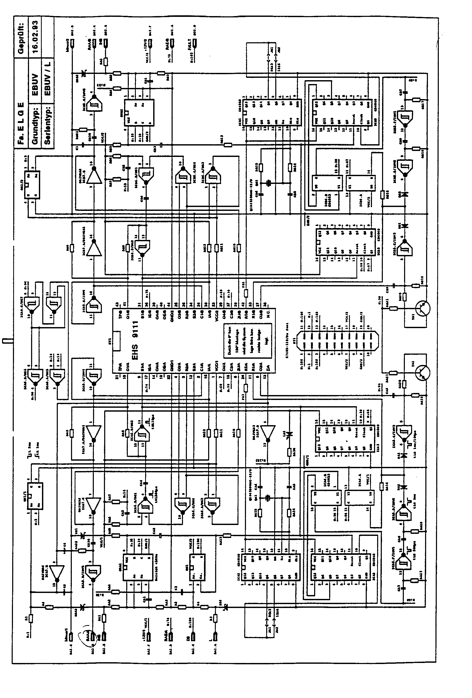


Kombination mit System
Die frontseitig abgebildete Einheit beinhaltet zwei voneinander unabhängige Überwachungssysteme. Die Drehbewegungsüberwachung wird zur Bestimmung des Stillstandes benötigt. Zur Sicherung der mechanischen Schutzeinrichtung wird die Sicherheitsrelaiskombination verwendet. Beide Systeme werden bevorzugt für Antriebe mit gefahrbringendem Bewegungsnachlauf genutzt und über einen Betriebsspannungsanschluß versorgt.The unit shown on the front contains two independent monitoring systems. Rotational motion monitoring is required to determine the standstill. The safety relay combination is used to secure the mechanical protective device. Both systems are preferably used for drives with dangerous movement lag and supplied via an operating voltage connection.
Das Überwachungssystem steht in zwei Ausführungen zur Verfügung:The monitoring system is available in two versions:

Zulassungen (siehe Bescheinigungen)
- - Schweizerische Unfallversicherungsanstalt (SUVA) Zulassung No "Beantragt"
- - Berufsgenossenschaft Fachausschuß Elektrotechnik (BG) Zulassung No A-ET "Beantragt"
- - Swiss Accident Insurance Fund (SUVA) approval No "applied for"
- - Employers' Liability Insurance Association Electrical Engineering Committee (BG) Approval No A-ET "Requested"
Damit die vereinbarte Funktion auch bei einem einzelnen Fehler nicht beeinträchtigt wird, muß eine redundante Signalauswertung verwendet werden. Das bedeutet, daß die Drehbewegungsinformation unabhängig voneinander zweikanalig zur Verfügung gestellt werden muß.To ensure that the agreed function is not impaired even in the event of a single fault, a redundant signal evaluation must be used. This means that the rotary motion information must be made available in two channels independently of one another.
Durch Abtastung, beispielsweise einer mit dem Antrieb gekoppelten Zahnscheibe über einen Sensor(Näherungsschalter), wird ein proportional zur Bewegung erzeugtes digitales Signal dem dynamischen Überwachungskanal "INA" zugeführt. Die maximal zulässige Drehbewegungsfrequenz 900Hz bzw. 1800Hz ist über die Geräteausführung EBUV 06 bzw. EBUV 12 festgelegt. Dadurch können je nach Zähneanzahl 6000... 18000 Umdrehungen pro Minute bearbeitet werden.By scanning, for example a toothed disc coupled to the drive via a sensor (proximity switch), a digital signal generated in proportion to the movement is fed to the dynamic monitoring channel "IN A ". The maximum permissible rotational movement frequency 900Hz or 1800Hz is defined via the device version EBUV 06 or
Die Betriebsspannungversorgung des Sensors erfolgt durch das Überwachungssystem über die Anschlußklemme "+ 12V".The sensor is powered by the monitoring system via the "+ 12V" terminal.
Durch, eine über den Arbeitskontakt des Antriebsschützes geführte Gleichspannung, wird zeitgleich mit der Drehbewegungsentstehung ein Signal dem statischen Überwachungskanal "L" zugeführt. In Verbindung mit der unter 2.2 beschriebenen Signalerzeugung wird eine zweikanalige Ansteuerung erreicht.Due to a DC voltage conducted across the normally open contact of the drive contactor, a signal is fed to the static monitoring channel "L" at the same time as the rotary movement occurs. In connection with the signal generation described under 2.2, a two-channel control is achieved.
Da bei Abschaltung des Antriebes ein Bewegungsnachlauf in Abhängigkeit der Masse entsteht, wird es notwendig, das statische Signal bis <20U/min zu speichern. Diese Funktion wird geräteintern über den Modulstecker MT gewährleistet und ist von 1...30s einstellbar. Nur beikonstanter Bewegungsnachlaufzeit z.B. durch Bremseinrichtungen ist diese Art der L-Signalansteuerung möglich. (Fehlerhafte, einkanalige Signalansteuerung entsteht durch manuelle, muskelabhängige Drehbewegungserzeugung).Since a motion overrun occurs depending on the mass when the drive is switched off, it is necessary to save the static signal up to <20 rpm. This function is guaranteed internally via the MT module connector and can be set from 1 ... 30s. Only constant movement lag time e.g. this type of L signal control is possible using braking devices. (Faulty, single-channel signal control is caused by manual, muscle-dependent rotary movement generation).
Beispielsweise durch Abtastung der bereits vorhandenen Zahnscheibe über einen zweiten Sensor (Näherungsschalter), wird ein proportional zur Bewegung erzeugtes digitales Signal dem dynamischen Überwachungskanal "INB"-zugeführt. Dieser dynamische Drehbewegungseingang arbeitet als frequenzabhängiger Schalter, und führt das dadurch erzeugte statische L-Signal geräteintern auf die Anschlußklemme "L". In Verbindung mit der unter 2.2 beschriebenen Signalerzeugung wird ebenfalls eine zweikanalige Ansteuerung erreicht. Bei nichtkonstanter Bewegungsnachlaufzeit ist diese Art der L-Signalansteuerung auszuwählen.For example, by scanning the already existing toothed disk via a second sensor (proximity switch), a digital signal generated in proportion to the movement is fed to the dynamic monitoring channel "IN B ". This dynamic rotary motion input works as a frequency-dependent switch, and leads the resulting static L signal internally to the terminal "L". In connection with the signal generation described under 2.2, a two-channel control is also achieved. This type of L signal control must be selected if the motion lag time is not constant.
Über zwei separate Modulstecker MT bzw. MD wird die der L-Signalansteuerung ausgewählt wobei aber immer nur eine angewendet werden kann.The L signal control is selected via two separate MT or MD module connectors, but only one can be used.
Nach Inbetriebnahme des Überwachnungssystems wird die Stillstandsmeldung nach ca. 3s über den Arbeitskontakt (13/14) bestätigt. Bei korrekter über Drehbewegung erzeugten Signalansteuerung des Achskreisinterface wird die Stillstandsmeldung durch Öffnen des Arbeitskontaktes beseitigt. Erst bei Unterschreitung einer durch die zähneabhängiger Restbewegung wird die Stillstandsmeldung erneut über den Arbeitskontakt bereitgestellt.After commissioning the monitoring system, the standstill message is confirmed after approx. 3s via the work contact (13/14). If the signal control of the axis circuit interface is generated correctly via rotary movement, the standstill message is eliminated by opening the work contact. The standstill message is only made available again via the work contact when the tooth-dependent residual movement falls below.

Durch Betriebshemmung, bei Auftreten eines Fehlers, wird eine sichere Stillstandserkennung gewährleistet. Über redundante (zweikanalige) Drehbewegungsauswertung und systeminterner Funktionsprüfung wird diese Forderung erreicht Diese Prüfung ist drehzahlabhängig und über die Auswahl der Zähnezahl festgelegt. Je nach Zähnezahl wird die Funktionsprüfung bei >40 bis < 140 U/min durchgeführt. Aus diesem Grund wird eine Mindestdrehzahl des Antriebs von >200U/min benötigt.Reliable standstill detection is guaranteed by operational inhibition when an error occurs. This requirement is achieved via redundant (two-channel) rotary motion evaluation and system-internal function test. This test is speed-dependent and is determined by the selection of the number of teeth. Depending on the number of teeth, the functional test is carried out at> 40 to <140 rpm. For this reason, a minimum drive speed of> 200rpm is required.
Bei fehlerhafter Ansteuerung (z.B. einkanalig) des Achskreises oder fehlerhaltes Überwachungssytem wird keine Stillstandsmeldung über den Arbeitskontakt erteilt. Dieser Zustand bleibt auch nach Beseitigung der Ursache vom Überwachungssystem gespeichert und kann nur durch erneute Inbetriebnahme quittiert werden.In the event of incorrect control (e.g. single-channel) of the axis circuit or faulty monitoring system, no standstill message is issued via the work contact. This status remains saved by the monitoring system even after the cause has been eliminated and can only be acknowledged by restarting.
Derfehlerhafte Zustand wird durch das Überwachungssystem über eine optische Kontrolle angezeit Zusätzlich wird ein Gleichspannungssignal (+24V/1A) an der Anschlußklemme "Out" bereitgestellt. Durch die oben beschriebene Maßnahme wird die Anzeige sowie die Störungsmeldung zurückgesetzt.The faulty state is indicated by the monitoring system via an optical control. In addition, a DC voltage signal (+ 24V / 1A) is provided at the "Out" connection terminal. The display and fault message are reset by the measure described above.
Damit die vereinbarte Funktion auch bei einem einzelnen Fehler nicht beeinträchtigt wird, muß eine redundante Signalauswertung verwendet werden. Das bedeutet, daß die Schutztürposition unabhängig voneinander diversitär zur Verfügung gestellt werden muß.To ensure that the agreed function is not impaired even in the event of a single fault, a redundant signal evaluation must be used. This means that the protective door position must be made available independently of one another in a diverse manner.
Die Sicherheitsrelaiskombination verfügt über zwei voneinander unabhängige Sicherheitskreise. Über die dadurch getrennte Signalbewertung wird eine relevante auf Schutzeinrichtung bezogene Aussage erreicht. Für die Anforderung der erhöhten Sicherheit ist auch eine Antriebsschützüberwachung vorgesehen. Auch die für den Entriegelungsvorgang benötigte Selbsthaltung wird durch die Sicherheitsrelaiskombination zur Verfügung gestellt. Das Resultat dieser Bewertung wird über einen dafür vorgesehenen Ausgangskontakt als Freigabsignal zur Verfügung gestellt.The safety relay combination has two independent safety circuits. A relevant statement relating to the protective device is achieved via the separate signal evaluation. Drive contactor monitoring is also provided for increased safety requirements. The self-locking required for the unlocking process is also provided by the safety relay combination. The result of this evaluation is made available as an enable signal via a dedicated output contact.
Bei offener Schutzeinrichtung und aktiviertem Magnetsystem wird durch eine standardisierte Kontaktverknüpfung des Verriegelungsmoduls ein Gleichspannungssignal an die Anschlußklemme "2" zugeführt. Dadurch wird die Möglichkeit einer Folgeansteuerung geräteintern an der Anschlußklemme "8" vorbereitet. Dieser Vorgang ist zusätzlich von der Kontaktvervielfähltigungsüberwachung an den Anschlußklemmen "X1/X2" abhängig. Nach Schließender Schutzeinrichtung wird zwangsläufig die seitherige Ansteuerung unterbrochen. Erst durch den elektromechanischen Verriegelungvorgang wird ein Gleichspannungssignal an der Anschlußklemme "8" zugeführt Bei fehlerfreier, geräteinterner Funktion wird durch diese Ansteuerung der Freigabepfad an der Anschlußklemme "33/34" aktiviert. Dieser Zustand bleibt bis zum Entriegelungsvorgang bestehen. Ein erneutes Freigabesignal kann nur dann erreicht werden, wenn der Handlungsablauf wie oben beschrieben durchgeführt wird.When the protective device is open and the magnet system is activated, a DC voltage signal is fed to the connection terminal "2" through a standardized contact linkage of the locking module. This prepares the possibility of a sequential control within the device at terminal "8". This process also depends on the multiplication of contacts at the "X1 / X2" connection terminals. After the protective device closes, the previous control is inevitably interrupted. Only through the electromechanical locking process is a DC voltage signal supplied to terminal "8". If the function of the device is error-free, this activation activates the release path at terminal "33/34". This state remains until the unlocking process. A new release signal can only be achieved if the procedure is carried out as described above.
Die Schutzeinrichtung signalisiert über relevante Kontaktansteuerung folgende Zustände:The protective device signals the following states via relevant contact control:
Sicherheitseinrichtung geöffnet; Verriegelung deaktiviert!Safety device opened; Locking deactivated!
Sicherheitseinrichtung geschlossen; Verriegelung aktivert! Dieser Betriebszustand wird durch die Sicherheitsrelaiskombination wie folgt ausgewertet:Safety device closed; Lock activated! This operating state is evaluated by the safety relay combination as follows:
Freigabepfad deaktiviert; keine Antriebzuschaltung möglich!Release path deactivated; no drive activation possible!
Freigabepfad aktiviert; Antriebszuschaltung möglich!Release path activated; Drive activation possible!
Diese Maßnahmen ergibt daß nur durch fehlerfreie Ansteuerung über die Schutzürpositionsschalter sowie die Funktion des Verriegelungsmoduls und natürlich auch eine fehlefreie Funktion derThese measures result that only by faultless control via the protective door position switch and the function of the locking module and of course also a faultless function of the
Sicherheitsrelaiskombination der Freigabekontaktkreis aktiviert wird.Safety relay combination of the enabling contact circuit is activated.
Wird die zuvor beschriebene Stillstandserkennung (3.1 bis 3.2) auf die Anschlußklemme "B1" geführt kann eine Entriegelung nur bei Stillstand des überwachten Antriebs vorgenommen werden. Durch diese kombinierte Maßnahme wird sichergestellt, daß der Arbeitsraum nur nach erreichen des Stillstandes betreten werden kann. Bei einem fehlerhaften Zustande wird die Freigabe und somit Antriebzuschaltung bzw. Eintritt in den Arbeitsraum sicher verhindert.If the previously described standstill detection (3.1 to 3.2) is connected to the "B1" connection terminal, it can only be unlocked when the monitored drive is at a standstill. This combined measure ensures that the work area can only be entered after it has come to a standstill. In the event of a faulty condition, the release and thus the activation of the drive or entry into the work area is reliably prevented.
Durch die selbstüberwachende Funktion beider Systeme kann eine kann eine zeitlich festgelegte Revision entfallen.Due to the self-monitoring function of both systems, a scheduled revision can be omitted.
Folgende elektrische Verbindungen sind zwischen dem zu überwachendem Antrieb und dem Überwachungssytem herzustellen.The following electrical connections must be made between the drive to be monitored and the monitoring system.
1 Eingang (INA) für die dynamische Signalansteuerung über Näherungsschalter1 input (IN A ) for dynamic signal control via proximity switches


1 Engang (INB) für die statische Signalansteuerung über Naherungsschalter (Daten wie Eingang INA)1 input (IN B ) for static signal control via proximity switch (data as input IN A )
1 Eingang reserviert für Entriegelungskontaktkreis (2)1 input reserved for unlocking contact circuit (2)

2 Eingänge reserviert für Entriegelungstaster (Öffner) 2 Eingänge reserviert für Verriegelungstaster (Schließer)


1 Ausgänge galvanisch getrennt, reserviert für die Drehbewegungsfreigabe


Nach Inbetriebnahme wird durch Schließen des Arbeitskontaktes "13/14" der Verriegelungsmagnet aktiviert. Dadurch erfolgt die vorbereitende Ansteuerung des Sicherheitskreises "K1.2". Nach Schließen der Schutzeinrichtung und Betätigung des Verriegelungstasters wird der Magnet deaktiviert. Aus der daraus entstehenden Ansteuerung des Sicherheitskreises "K1.8" wird der Freigabekontakt "33/34" geschlossen. Eine Betätigung des Tasters "Ein" aktiviert den Schütz "K1", "Über die Antriebsbewegung wird der Arbeitskontakt (Stillstandserkennung) "13/14" geöffnet. Durch diese Maßnahme wird eine Entriegelung sicher verhindert.After start-up, the locking magnet is activated by closing the normally open contact "13/14". The preparatory activation of the safety circuit "K1.2" takes place. After closing the protective device and pressing the locking button, the magnet is deactivated. The release contact "33/34" is closed from the resulting activation of the safety circuit "K1.8". Pressing the "On" button activates the contactor "K1", "The work contact (standstill detection)" 13/14 "is opened via the drive movement. This measure reliably prevents unlocking.
Nach erreichen des Stillstandes wird durch Schließen des Arbeitskontaktes "13/14" die Entriegelung vorbereitet. Bei Entriegelung wird der Freigabekontakt "33/34" geöffnet und eine Antriebszuschaltung sicher verhindert.After reaching standstill, the unlocking is prepared by closing the work contact "13/14". When unlocked, the release contact "33/34" is opened and drive activation is reliably prevented.
Die fehlerfreie Funktion des Schützes "K1" wird über die Kontaktvervielfältigung "X1/X2" überwacht.The correct functioning of the contactor "K1" is monitored via the contact duplication "X1 / X2".
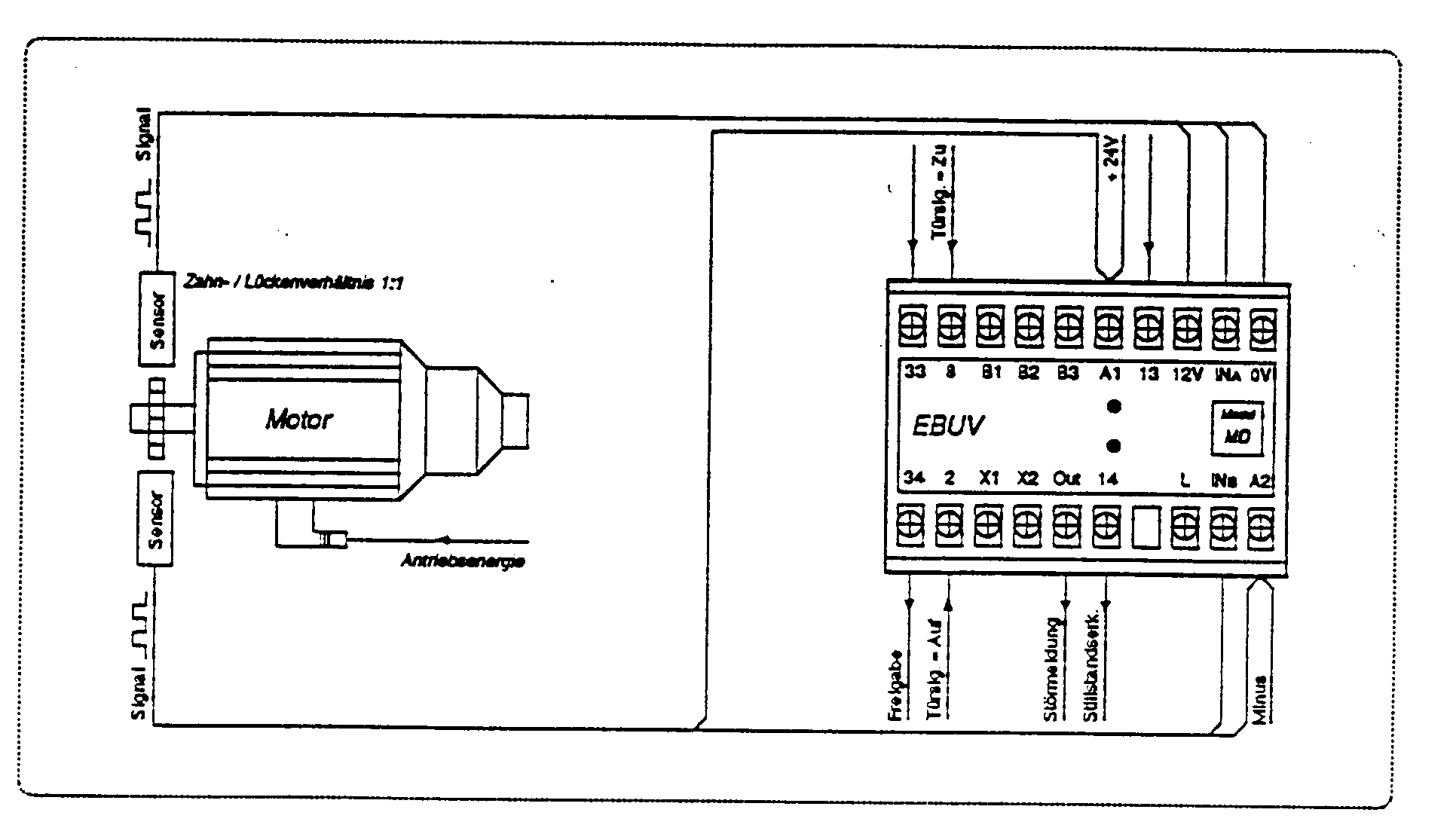
Diese Ansteuerungsmethode erfordert folgende Sensormontage:This control method requires the following sensor assembly:

Weitere Hinweise zur Montage müssen bei den Sensorherstellern erfragt werden.Further information on assembly must be obtained from the sensor manufacturers.


Bei fehlerbehafteter Funktion müssen die hier aufgeführten Punkte geprüft bzw. Maßnahmen eingeleitet werden.If the function is faulty, the points listed here must be checked or measures initiated.
- - Anschlußbedingungen?- connection conditions?
- - Spannungsversorgung des Gerätes sowie der Sensorik?- Power supply for the device and the sensors?
- - Ansteuerung der Sicherheitskreise sowie der Kontaktvervielfältigung?- Control of the security circles and the duplication of contacts?
- - Ansteuerung des Verriegelungsmagneten?- control of the locking magnet?
- - Ansteuerung der Achskreise?- control of the axis circles?
- - Systemfremde elektromagnetische Störgrößen? Um die größtmöglichste Störfestigkeit einer Anlage zu erreichen, sind EMV-Maßnahmen z.B. RC-Glieder für die Schützpulen seitens Steuerungshersteller notwendig.- Non-system electromagnetic disturbances? In order to achieve the greatest possible interference immunity of a system, EMC measures are e.g. RC elements required for the contactor coils from the control manufacturer.
- - Systemfremde elektromagnetische Störgrößen? Um die größtmöglichste Störfestigkeit einer Achskreisansteuerung zu erreichen, sind EMV-Maßnahmen wie getrennte Energie- und Steuerkabelführungen notwendig.- Non-system electromagnetic disturbances? In order to achieve the greatest possible immunity to interference from an axis circuit control, EMC measures such as separate power and control cable routing are necessary.
- - Kontaktabhängige L-Signalerzeugung? Über eine externe zusätzliche Belastung kann der für die Schaltsicherheit geforderte Kontaktstrom erhöht werden.- Contact-dependent L signal generation? The contact current required for switching reliability can be increased via an external additional load.
- - Sensoren auf richtige Montage und störungsfreie Signalerzeugung? Bei nichtausreichender Montagefestigkeit der Sensoren können mechanische Schwingungen auftreten und somit eine Bereichsüberschreitung verursachen.- sensors for correct installation and interference-free signal generation? If the sensors are not sufficiently rigid, mechanical vibrations can occur and thus cause the range to be exceeded.
- - Bereichsüberschreitung? Um die größtmöglichste Funktionsicherheit zu erreichen, sollte die Drehbewegungsfrequenz 90% des zulässigen Bereichs nicht überschreiten.- Out of range? In order to achieve the greatest possible functional reliability, the rotational movement frequency should not exceed 90% of the permissible range.
- - Funktionsmodulsteckerauswahl auf die dazu gehörende Ansteuerungsart?- Function module connector selection on the corresponding control type?
Wenn auch bei richtiger Anschlußbedingung sowie fehlerfreier Ansteuerung eine Funktionsstörung auftritt, wird eine Überprüfung des Überwachungssystems beim Hersteller (Fa. ELGE) notwendig.If a malfunction occurs even with the correct connection conditions and error-free control, the manufacturer's monitoring system (ELGE) must be checked.
Claims (9)
Applications Claiming Priority (2)
| Application Number | Priority Date | Filing Date | Title |
|---|---|---|---|
| DE4309007 | 1993-03-20 | ||
| DE19934309007 DE4309007A1 (en) | 1993-03-20 | 1993-03-20 | Safety monitoring method for protective devices of machines and device for carrying out the method |
Publications (1)
| Publication Number | Publication Date |
|---|---|
| EP0617225A1 true EP0617225A1 (en) | 1994-09-28 |
Family
ID=6483353
Family Applications (1)
| Application Number | Title | Priority Date | Filing Date |
|---|---|---|---|
| EP94104030A Withdrawn EP0617225A1 (en) | 1993-03-20 | 1994-03-16 | Method and apparatus for safety monitoring of safety devices for machines |
Country Status (2)
| Country | Link |
|---|---|
| EP (1) | EP0617225A1 (en) |
| DE (1) | DE4309007A1 (en) |
Cited By (5)
| Publication number | Priority date | Publication date | Assignee | Title |
|---|---|---|---|---|
| EP0754521A1 (en) * | 1995-02-07 | 1997-01-22 | The Nippon Signal Co. Ltd. | Safety securing device |
| EP0760446A1 (en) * | 1995-02-07 | 1997-03-05 | The Nippon Signal Co. Ltd. | Safety ensuring apparatus |
| DE102012010003A1 (en) * | 2012-05-22 | 2013-11-28 | Bizerba Gmbh & Co Kg | safety device |
| DE102018215536A1 (en) * | 2018-09-12 | 2020-03-12 | Siemens Aktiengesellschaft | Contact monitoring device for a safety-critical triggering device of a switching device |
| CN111443734A (en) * | 2020-03-20 | 2020-07-24 | 深圳市华昇智能科技有限公司 | Multi-channel operation control system and method for compact shelving |
Families Citing this family (1)
| Publication number | Priority date | Publication date | Assignee | Title |
|---|---|---|---|---|
| US6389875B1 (en) * | 1998-10-02 | 2002-05-21 | Ralph L. Barnett | Zero speed indicating devices and process of testing same |
Citations (4)
| Publication number | Priority date | Publication date | Assignee | Title |
|---|---|---|---|---|
| GB1470997A (en) * | 1975-05-22 | 1977-04-21 | Gen Motors Ltd | Spin-drier machines |
| EP0465710A1 (en) * | 1990-07-12 | 1992-01-15 | ELGE ELEKTRONIK-GERÄTEWERK GmbH. & Co. | Device for the safety monitoring of safety devices, for a normal or elevated safety level of multiaxled machines which execute turning motions |
| EP0501218A2 (en) * | 1991-02-26 | 1992-09-02 | ELGE ELEKTRONIK-GERÄTEWERK GmbH. & Co. | Control system for locking a door or a protective hood of a safety device for machines |
| DE9304170U1 (en) * | 1993-03-20 | 1993-05-27 | Elge Elektronik-Gerätewerk GmbH & Co i.K., 91626 Schopfloch | Safety monitoring device for protective devices on machines |
-
1993
- 1993-03-20 DE DE19934309007 patent/DE4309007A1/en not_active Withdrawn
-
1994
- 1994-03-16 EP EP94104030A patent/EP0617225A1/en not_active Withdrawn
Patent Citations (4)
| Publication number | Priority date | Publication date | Assignee | Title |
|---|---|---|---|---|
| GB1470997A (en) * | 1975-05-22 | 1977-04-21 | Gen Motors Ltd | Spin-drier machines |
| EP0465710A1 (en) * | 1990-07-12 | 1992-01-15 | ELGE ELEKTRONIK-GERÄTEWERK GmbH. & Co. | Device for the safety monitoring of safety devices, for a normal or elevated safety level of multiaxled machines which execute turning motions |
| EP0501218A2 (en) * | 1991-02-26 | 1992-09-02 | ELGE ELEKTRONIK-GERÄTEWERK GmbH. & Co. | Control system for locking a door or a protective hood of a safety device for machines |
| DE9304170U1 (en) * | 1993-03-20 | 1993-05-27 | Elge Elektronik-Gerätewerk GmbH & Co i.K., 91626 Schopfloch | Safety monitoring device for protective devices on machines |
Cited By (7)
| Publication number | Priority date | Publication date | Assignee | Title |
|---|---|---|---|---|
| EP0754521A1 (en) * | 1995-02-07 | 1997-01-22 | The Nippon Signal Co. Ltd. | Safety securing device |
| EP0760446A1 (en) * | 1995-02-07 | 1997-03-05 | The Nippon Signal Co. Ltd. | Safety ensuring apparatus |
| EP0754521A4 (en) * | 1995-02-07 | 1998-05-20 | Nippon Signal Co Ltd | Safety securing device |
| EP0760446A4 (en) * | 1995-02-07 | 1998-05-20 | Nippon Signal Co Ltd | Safety ensuring apparatus |
| DE102012010003A1 (en) * | 2012-05-22 | 2013-11-28 | Bizerba Gmbh & Co Kg | safety device |
| DE102018215536A1 (en) * | 2018-09-12 | 2020-03-12 | Siemens Aktiengesellschaft | Contact monitoring device for a safety-critical triggering device of a switching device |
| CN111443734A (en) * | 2020-03-20 | 2020-07-24 | 深圳市华昇智能科技有限公司 | Multi-channel operation control system and method for compact shelving |
Also Published As
| Publication number | Publication date |
|---|---|
| DE4309007A1 (en) | 1994-09-22 |
Similar Documents
| Publication | Publication Date | Title |
|---|---|---|
| DE10011211B4 (en) | Safety relay and safety relay system | |
| DE4340715C1 (en) | Control and regulation for a door driven by an electromechanical motor | |
| EP0465710B1 (en) | Device for the safety monitoring of safety devices, for a normal or elevated safety level of multiaxled machines which execute turning motions | |
| EP0742503A2 (en) | Numerical control device for a machine-tool or a robot | |
| EP1493064A2 (en) | Device for the error-proof switching off of an electric consumer, particularly in industrial production plants | |
| EP1254400B1 (en) | Circuit arrangement for the safe shutdown of an installation, in particular a machine installation | |
| DE102011002481A1 (en) | control system | |
| EP0501218A2 (en) | Control system for locking a door or a protective hood of a safety device for machines | |
| EP1847891A1 (en) | Secure parameterisation of a security switching device | |
| EP1629513B1 (en) | Control device for safety-critical components and corresponding method | |
| EP0264350A1 (en) | Processor-controlled plant as well as a supervising circuit, especially for such a plant | |
| DE3837218C2 (en) | ||
| EP0924585B1 (en) | Surveillance device for garage door drive | |
| EP0617225A1 (en) | Method and apparatus for safety monitoring of safety devices for machines | |
| EP3465898B1 (en) | Soft starter, operating method, and switching system | |
| DE4432768C2 (en) | Circuit arrangement for monitoring safety-relevant machine parameters and operating states during movement processes | |
| DE102004019284A1 (en) | Device for operating a synchronous motor | |
| EP3475966B1 (en) | Safety-oriented switching device | |
| EP0470441A2 (en) | Method for communication of an acknowledgement signal for operating a robot | |
| DE19715098A1 (en) | Monitoring circuit | |
| EP2305521B1 (en) | Vehicle steering lock apparatus with a safety circuit which receives lock release signals | |
| DE4432759A1 (en) | Safety control and monitoring module e.g. for CNC machines and industrial robots | |
| DE9304170U1 (en) | Safety monitoring device for protective devices on machines | |
| DE3919558C2 (en) | ||
| DE19715013A1 (en) | Circuit for starting a machine or the like and method for controlling a start of a machine |
Legal Events
| Date | Code | Title | Description |
|---|---|---|---|
| PUAI | Public reference made under article 153(3) epc to a published international application that has entered the european phase |
Free format text: ORIGINAL CODE: 0009012 |
|
| AK | Designated contracting states |
Kind code of ref document: A1 Designated state(s): AT BE CH DE ES FR GB IT LI SE |
|
| 17P | Request for examination filed |
Effective date: 19941115 |
|
| K1C1 | Correction of patent application (title page) published |
Effective date: 19940928 |
|
| 17Q | First examination report despatched |
Effective date: 19970311 |
|
| STAA | Information on the status of an ep patent application or granted ep patent |
Free format text: STATUS: THE APPLICATION HAS BEEN WITHDRAWN |
|
| 18W | Application withdrawn |
Withdrawal date: 19970710 |