EP0616397B1 - Electrical connector with short circuiting facility - Google Patents
Electrical connector with short circuiting facility Download PDFInfo
- Publication number
- EP0616397B1 EP0616397B1 EP94104115A EP94104115A EP0616397B1 EP 0616397 B1 EP0616397 B1 EP 0616397B1 EP 94104115 A EP94104115 A EP 94104115A EP 94104115 A EP94104115 A EP 94104115A EP 0616397 B1 EP0616397 B1 EP 0616397B1
- Authority
- EP
- European Patent Office
- Prior art keywords
- housing
- shunting
- connector
- terminals
- shunt
- Prior art date
- Legal status (The legal status is an assumption and is not a legal conclusion. Google has not performed a legal analysis and makes no representation as to the accuracy of the status listed.)
- Expired - Lifetime
Links
- 238000003780 insertion Methods 0.000 claims description 5
- 230000037431 insertion Effects 0.000 claims description 5
- 230000013011 mating Effects 0.000 description 9
- 238000006073 displacement reaction Methods 0.000 description 4
- 238000009413 insulation Methods 0.000 description 4
- 239000004020 conductor Substances 0.000 description 3
- 230000036316 preload Effects 0.000 description 2
- 230000007797 corrosion Effects 0.000 description 1
- 238000005260 corrosion Methods 0.000 description 1
- 230000001419 dependent effect Effects 0.000 description 1
- 230000005674 electromagnetic induction Effects 0.000 description 1
- 238000010304 firing Methods 0.000 description 1
- PCHJSUWPFVWCPO-UHFFFAOYSA-N gold Chemical compound [Au] PCHJSUWPFVWCPO-UHFFFAOYSA-N 0.000 description 1
- 239000010931 gold Substances 0.000 description 1
- 229910052737 gold Inorganic materials 0.000 description 1
- 230000014759 maintenance of location Effects 0.000 description 1
- 239000002184 metal Substances 0.000 description 1
- 229910052751 metal Inorganic materials 0.000 description 1
- 238000007747 plating Methods 0.000 description 1
- 230000000750 progressive effect Effects 0.000 description 1
- 230000000717 retained effect Effects 0.000 description 1
Images


Classifications
-
- H—ELECTRICITY
- H01—ELECTRIC ELEMENTS
- H01R—ELECTRICALLY-CONDUCTIVE CONNECTIONS; STRUCTURAL ASSOCIATIONS OF A PLURALITY OF MUTUALLY-INSULATED ELECTRICAL CONNECTING ELEMENTS; COUPLING DEVICES; CURRENT COLLECTORS
- H01R13/00—Details of coupling devices of the kinds covered by groups H01R12/70 or H01R24/00 - H01R33/00
- H01R13/66—Structural association with built-in electrical component
- H01R13/70—Structural association with built-in electrical component with built-in switch
- H01R13/703—Structural association with built-in electrical component with built-in switch operated by engagement or disengagement of coupling parts, e.g. dual-continuity coupling part
- H01R13/7031—Shorting, shunting or bussing of different terminals interrupted or effected on engagement of coupling part, e.g. for ESD protection, line continuity
- H01R13/7032—Shorting, shunting or bussing of different terminals interrupted or effected on engagement of coupling part, e.g. for ESD protection, line continuity making use of a separate bridging element directly cooperating with the terminals
Definitions
- This invention refers to an electrically shunted connector as set forth in the preamble of claim 1.
- This invention relates to an electrical connector having a short circuiting facility and to a short circuiting spring therefore, the invention particularly, but not exclusively, concerning such a connector for use and protecting from accidental firing, an electrical detonator for inflating an automotive air bag.
- crash sensors disposed in the forward part of a motor vehicle are connected to the detonators of air bags before the front seats of the vehicle.
- a detonator may be connected to ignition voltage means by means of an electrical connector, the parts of which can be unmated to allow the air bag and/or the detonator thereof to be removed for replacement testing, and the like.
- an electrical connector the parts of which can be unmated to allow the air bag and/or the detonator thereof to be removed for replacement testing, and the like.
- the detonator which is necessarily very sensitive, being accidently actuated so that the air bag is accidently inflated. This may occur, for example as a result of leakage or other stray voltage, or accidently applied current, energizing the ignition current supply leads of the detonator for example, by electro magnetic induction.
- an electrical connector assembly comprising a receptacle part and a pin carrying part for mating with, the receptacle part comprising an insulating housing defining first and second space parallel through cavities each receiving a pin receptacle terminal therein and intermediate said cavities a short circuiting spring having a normal first position which a contact surfaces thereof engage against the terminals to provide a shorted electrical path therebetween.
- a displaced second position in which the contact surfaces are cut of engagement with the pin terminals is also provided, where the pin carrying part comprises an insulating member with projecting pins for mating with the receptacle terminals as the parts are being mated and a camming member for engaging the short circuiting spring to displace it from the second position when partially mated, the short circuiting spring resiling from its second position to its first position upon withdrawal of the camming member from the short circuiting spring.
- the short circuiting spring which has been stamped and formed from a single piece of sheet metal stock, has a pair of wings projecting therefrom, the free ends of which engage the terminals of the first position of the short circuiting spring.
- the contact surfaces of the wings are necessarily sheared surfaces which are very narrow and unsuitable for selective plating with the corrosion resistant high electrically conductive material such as gold.
- EP-A-0 389 779 discloses an electrical connector wherein a shunt terminal is inserted into an inner connector housing from the front end thereof. An outer housing is slid over the inner housing thereby fixing the shunt terminal in a shunting terminal passageway.
- the shunting terminal according to this reference is not slid into its passageway but only mounted into a groove which is open to the front end as well as to one side because the side wall is constituted by the outer housing which is slid over the inner housing.
- the invention provides an electrically shunted connector as defined in claim 1. Preferred embodiments are defined in the dependent claims.
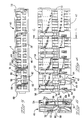
- an outer insulating housing is shown generally at 2 comprising a housing portion 4 and a locking pinion member 6 of the type shown in DE-U-8714016.
- the locking pinion member 6 pivots about a pin 8 and has rachet teeth 10 and a lever arm 12.
- the locking pinion member 6 is pivotable to the position shown in phantom in Figure 1, whereby a guiding edge 14 is now disposed in a vertical plane for guiding the housing 2 into its associated header assembly (not shown). Rotation of the lever arm 12 back to the position shown in Figure 1 moves the housing downwardly and in to mating engagement with the tab header.
- the housing 2 is shown including a cavity 16 which opens towards the left hand end of the housing as viewed in Figure 1, defined by side walls 18 having inner surfaces 20.
- the housing also includes a lower wall portion 22 defining an inner surface 24 and a front mating surface 26.
- the side walls 18 include longitudinally extending guide rails 28 along the length thereof, as will be explained in greater detail herein.
- the front face 26 is shown as including a plurality of pin receiving openings at 30 extending in a longitudinally extending row, as well as a plurality of rectangular shaped openings 32, where each opening 32 spans the distance of two openings 30, as will be described further herein.
- an inner housing comprising a front mating face at 42, a top surface 44, a lower surface 36, side surfaces 48 and 50, and an end surface 51.
- the housing 40 includes a plurality of terminal receiving passageways 52 for receiving conventional style terminals 54 where the terminals include an insulation displacement contact at 56 ( Figure 4) and cantilever spring beam contacts 58 ( Figure 6).
- the housing is formed with windows at 60 which forms a transverse shoulder at 62 to cooperate with the locking lance 64 of the electrical terminal 54.
- a rear edge 66 of a terminal is positioned adjacent to an opening 68 in the housing to provide a secondary locking mechanism as will be described in greater detail herein.
- the housing 40 further includes a plurality of pin receiving openings at 70 as shown in Figures 5 and 6, which cooperate with the pin receiving openings 30 in the outer housing, for example when comparing Figures 3 and 5. It should also be noted that, in a similar manner to the outer housing 4, as shown in Figure 3, the lower row includes only passageways 52, to accommodate an entire row of terminals 54. Finally the housing 40, as best shown in Figure 4 includes openings at 72 which allow access for mass termination of insulated conductors into the insulation displacement slot 56 through the opening 72. Integral shoulders 74 overlie the insulation displacement member 56 for retention purposes, yet allow mass termination of the wire.
- the housing 40 also includes a plurality of passageways 80, and in the specific embodiment five such passageways being shown, which are profiled to receive a shunt spring to be described more fully herein.
- the passageway 80 is somewhat U-shaped including side-by-side channels 82 having an intermediate wall 84 separating the two channels 82 into discrete passageways.
- a second longitudinal opening is provided at 88 which extends the length of the housing 40 ( Figure 4) forming an upper surface 90 of the wall 84.
- a locking shoulder 92 is positioned behind the top surface 90 and thereafter steps down to a recessed surface 94.
- a window is formed at 96 through the central wall 98 which separates the two rows of terminals.
- the window 96 thus communicates with one of the terminal receiving passageways 52 directly below the window.
- the windows 96 are positioned within the separate channels 82 separated by the wall 84 and therefore the windows 96 provide access to two adjacent terminal receiving passageways 52 in the lower row of terminal passageways.
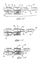
- a shunt spring is shown at 100 including a base wall 102 having two reversely bent cantilever springs at 104 bent around a U-shaped bight portion 106.
- the cantilever spring beams 104 extend rearwardly and have a projection at 108 thereby forming a contact surface at 110.
- the projection 108 is then lowered to a portion 112, and thereafter the free end 114 of the spring arm 104 extends obliquely towards the base portion 102.
- windows 116 are stamped out of the base portion 102 which expose the free ends 114 of the cantilever springs 104, from the side facing the lower base portion 102, as best viewed in Figure 7.
- a tab portion 120 is retained, and side walls 122 are bent upwardly providing the tab portions 120 in a common plane with the side walls 122. As best shown in Figure 8, two such side walls are formed to provide rigidity and protection for the cantilever spring beams 104.
- the spring arms are reversely bent from the plane forming the base portion 102 around the bight portion 106 and thereafter, tabs 125 are bent over the cantilever beams to preload the cantilever spring arms 104 against a lower surface of the tabs 125 as best shown in Figure 9.
- a locking lance 126 is stamped out of the base portion 102 along the axial center line of the base portion and is bent inwardly towards the cantilever spring arm as best shown in Figure 9.
- an opening at 130 is stamped out of the shunt spring base wall 102 and side walls 122 thereby forming a locking edge surface 132 as will be described in greater detail herein.
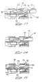
- the terminals 54 are first inserted into the respective terminal receiving passageways 52 through the rear wall 51 ( Figure 4) with the IDC slot 56 below the flanges 74 to a position where the locking lances 64 snap behind the locking shoulder 62 providing a primary lock for the electrical terminals 54.
- the rear shoulder 66 is positioned adjacent to the surface of the window 68 for secondary locking purposes of the terminal as will be described herein.
- the electrical terminal contact 54 is shown in its fully received position in Figure 10.
- the shunt spring 100 is poised for receipt within the passageway 80.
- the shunt spring 100 is being positioned through the front face 42 of the inner housing 40 with the bight portion 106 leading the contact.
- the shunt springs 100 are positioned within the passageways 80 such that the U-shape formed by the base wall 102 and the side walls 122 form an inverted U as best shown in Figure 5. This positions the base wall 102 above the middle wall 84 and each of the cantilever spring beam arms 104 in their respective passageways 82.
- the position of the shunt spring 100 within the cavity 80 is easily achieved as the shunt spring 100, and more particularly the cantilever spring arm beams 104 are held at a prestressed condition by the tabs 125.
- the base wall 102 is now positioned beneath the side wall 44 of the housing 44 and the insertion of the shunt spring is being assisted by the guidance of the base wall 102 together with the lower edges of the side walls 122.
- the tabs 125 which hold these cantilever beams 104 in a prestressed condition, are positioned along the same line as the lower edge 123 of the side walls 122 thereby preventing stubbing of the tab portion 125 during the insertion of the shunt contact 100.
- the base wall 102 of the shunt spring has two windows at 116 which allow passage therethrough of the free ends 114 of the cantilever spring beams. This allows for easy flexing of the cantilever spring beam arm, and without over stressing the free end 114.
- a window 49 is positioned above the passageways 82 forward of the forwardly facing edge 45 of the housing side wall 44. This opening 49, as viewed in Figure 14, allows the free end 114 of the shunt spring to continue forward while still extending through the window 116 through the base wall 102.
- the shunt spring 100 is in its fully forward position when the tab 120 abuts the forwardly facing surface 45 of the housing. In this position, the contact portion 110 of the shunt spring is now aligned with the window 96 which allows the shunt projection 108 to resiliently deflect against the contact 54. It should also be appreciated that in this position, the locking lance 126 is locked against the shoulder 92 ( Figure 10) to retain the shunt spring in its fully locked position. It should also be appreciated that the shoulder 132 ( Figure 9 and 15) of the shunt spring 100 is positioned against the surface forming the window 88 ( Figure 6) which will assist in secondarily locking the shunt spring in position.
- the insulated conductors of a cable to be terminated to the terminals 54 can now be positioned above the respective insulation displacement portions 56 and be terminated through the windows 72 ( Figure 4) to the respective terminals 54.
- the inner housing 40 is now longitudinally slidable into the opening 16 from the left to the right as viewed in Figure 1 such that the longitudinal rails 28 along the side walls 18 of the housing 4 are received within respective longitudinal openings 68 and 88. This positions the longitudinal rails 28 against the edge 66, of the terminals 54, and against the edge 132 ( Figures 9 and 15) of the shunt springs 100.
- an end cap (not shown) is slidably received over the ribs 27 ( Figure 1) in a direction transverse to the front mating face, and is snapped in place to retain the inner housing 40.
- the assembled connector can now be interconnected to a tab header of the type generally described in the aforementioned utility model, such that rotation of the pivot arm 6 brings the fully assembled connector into mating engagement with the tab header.
- the tab header would include insulating tabs located proximate to the various openings 32 ( Figure 3) for making contact with the obliquely extending free end 114 of the shunt spring 100, which, when in the fully mated condition with the tab header, removes the respective cantilever beams 104 from shunting contact with the two adjacent terminals 54.
Landscapes
- Details Of Connecting Devices For Male And Female Coupling (AREA)
- Connector Housings Or Holding Contact Members (AREA)
- Coupling Device And Connection With Printed Circuit (AREA)
Description
Claims (8)
- An electrically shunted connector comprising a connector housing (4) having at least two rows of terminal receiving passageways (52), where at least some of said passageways carry signal carrying contacts (54), said housing further comprising shunting terminal passageways (80) opposed to some of said terminal receiving passageways carrying shunting terminals (100) for commoning two signal carrying contacts in the opposing row, the shunting terminal passageways (80) in the housing being profiled for front loading of said shunting terminals (100) therein, characterized in that said housing (4) and shunt terminals (100) have relief areas to prevent overstressing said shunt terminals upon insertion, therein, and in that lead-in sections (114) of the shunting terminals extend forwardly towards said front face (42) of said housing (4) and obliquely across the associated shunting terminal passageway (80) and said relief area in said shunting terminals is formed by openings (116) opposing said lead-in sections (114), allowing said lead-in sections to pass therethrough.
- The connector of claim 1, characterized in that said housing relief area is comprised of a transverse opening (45) spanning said shunting terminal receiving passageway (80).
- The connector of claim 1 or 2, characterized in that said shunting terminals (100) are comprised of a base portion (102) having a reversely bent leg portion (104), where a contact section (110) is formed on said reversely bent leg (104) at a projection (108).
- The connector of any of claims 1-3, characterized in that said shunting terminals (100) comprise base wall (102), folded-up side walls and two shunt contacts extending forwardly from a front edge of said base wall.
- The connector of any of claims 1-4, characterized in that tab portions (125) extend from edges of said side walls (122) and are folded over the shunt contact arms (104) to hold them in a prestressed condition.
- The connector of any of claims 1-5, characterized in that a transverse opening (130) is formed through the base wall (102) forming a locking edge (132).
- The connector of any of claims 1-6, characterized in that the shunting terminal receiving cavities (80) include a window (96) communicating to corresponding signal carrying terminal cavities (70).
- The connector of claim 6, characterized in that said housing (40) has a transverse opening (68) axially aligned with opening (130) and is slidably receivable into an outer housing shell (2) having a locking arm (128) receivable in said opening (68) of said housing (40) and into said opening (130) of said shunting terminals (100).
Applications Claiming Priority (2)
| Application Number | Priority Date | Filing Date | Title |
|---|---|---|---|
| GB9305758 | 1993-03-19 | ||
| GB939305758A GB9305758D0 (en) | 1993-03-19 | 1993-03-19 | Electrical connector having short circuiting facility |
Publications (3)
| Publication Number | Publication Date |
|---|---|
| EP0616397A2 EP0616397A2 (en) | 1994-09-21 |
| EP0616397A3 EP0616397A3 (en) | 1996-01-24 |
| EP0616397B1 true EP0616397B1 (en) | 1998-09-16 |
Family
ID=10732397
Family Applications (1)
| Application Number | Title | Priority Date | Filing Date |
|---|---|---|---|
| EP94104115A Expired - Lifetime EP0616397B1 (en) | 1993-03-19 | 1994-03-16 | Electrical connector with short circuiting facility |
Country Status (6)
| Country | Link |
|---|---|
| US (1) | US5494450A (en) |
| EP (1) | EP0616397B1 (en) |
| JP (1) | JP3400079B2 (en) |
| DE (1) | DE69413279T2 (en) |
| ES (1) | ES2123070T3 (en) |
| GB (1) | GB9305758D0 (en) |
Families Citing this family (21)
| Publication number | Priority date | Publication date | Assignee | Title |
|---|---|---|---|---|
| JP3253805B2 (en) * | 1994-07-08 | 2002-02-04 | タイコエレクトロニクスアンプ株式会社 | Short-circuit electrical connector |
| JPH0864309A (en) * | 1994-08-25 | 1996-03-08 | Sumitomo Wiring Syst Ltd | Short-circuitting connector |
| US5895282A (en) * | 1996-05-24 | 1999-04-20 | Thomas & Betts Corporation | Connector for airbag gas generator |
| US5993230A (en) * | 1996-08-12 | 1999-11-30 | Thomas & Betts International, Inc. | Orientationless squib connector assembly for automotive air bag assemblies |
| US6164479A (en) * | 1996-09-06 | 2000-12-26 | Ultra Flota Corp. | Internal floating roof tank and peripheral seal |
| DE69622720T2 (en) * | 1996-11-04 | 2003-03-13 | Molex Inc., Lisle | Electrical connector assembly with short circuit device |
| US6036534A (en) * | 1997-02-26 | 2000-03-14 | 3M Innovative Properties Company | Low profile shunt connector |
| EP0899825B1 (en) * | 1997-08-29 | 2003-02-12 | The Whitaker Corporation | Short circuit terminal and connector |
| BR9802812A (en) * | 1997-08-29 | 1999-11-03 | Whitaker Corp | short-circuit terminal and connector. |
| US6276953B1 (en) | 1997-12-04 | 2001-08-21 | Thoma & Betts International, Inc. | Orientationless squib connector assembly for automotive air bag assemblies |
| JP3374735B2 (en) | 1997-12-12 | 2003-02-10 | 住友電装株式会社 | connector |
| JP3598811B2 (en) * | 1998-05-14 | 2004-12-08 | 住友電装株式会社 | Short-circuit terminal and mating detection connector incorporating this |
| US6186805B1 (en) | 1999-08-31 | 2001-02-13 | Molex Incorporated | Short circuit electrical connector |
| US6361356B1 (en) * | 2000-10-03 | 2002-03-26 | Delphi Technologies, Inc. | Electrical connector position assurance device |
| FR2848030B1 (en) * | 2002-12-03 | 2005-01-14 | Valeo Electronique Sys Liaison | ELECTRICAL CONNECTOR. |
| DE102006033173A1 (en) * | 2006-07-18 | 2008-01-24 | Robert Bosch Gmbh | Electrical plug connection for airbag control device, has short circuit bridging unit displaced with respect to housing during separation or disconnection of plugs, and electrically connecting contacts with each other by displacement |
| US7645151B2 (en) * | 2007-03-22 | 2010-01-12 | Tyco Electronics Corporation | Shunted electrical connector and shunt therefore |
| DE102009056517B4 (en) | 2009-12-02 | 2011-07-28 | Tyco Electronics AMP GmbH, 64625 | Connector assembly with first and second connector and mating connector |
| US9077097B2 (en) | 2012-08-03 | 2015-07-07 | Honeywell International Inc. | Module connector for uninterrupted communication |
| EP2693568B1 (en) * | 2012-08-03 | 2016-08-24 | Honeywell International Inc. | Module connector for uninterrupted communication |
| JP6538431B2 (en) * | 2015-06-03 | 2019-07-03 | 本多通信工業株式会社 | Electrical contact |
Family Cites Families (9)
| Publication number | Priority date | Publication date | Assignee | Title |
|---|---|---|---|---|
| US3431536A (en) * | 1967-07-05 | 1969-03-04 | Byron W Olson | Wire termination electrical junction and contact retention system |
| US3597726A (en) * | 1969-04-07 | 1971-08-03 | Appleton Electric Co | Terminal block connectors |
| FR2174358A5 (en) * | 1972-02-29 | 1973-10-12 | Amp France Sa | |
| JP2627942B2 (en) * | 1988-10-27 | 1997-07-09 | 日本エー・エム・ピー株式会社 | Airbag connector |
| DE3909912A1 (en) * | 1989-03-25 | 1990-09-27 | Bosch Gmbh Robert | MULTIPOLE CONNECTOR |
| JPH0620303Y2 (en) * | 1989-08-09 | 1994-05-25 | 富士重工業株式会社 | Electrical connector coupling confirmation device |
| EP0446572B1 (en) * | 1990-03-13 | 1995-01-11 | KRONE Aktiengesellschaft | Telecommunications and data systems engineering terminal block |
| GB9012059D0 (en) * | 1990-05-30 | 1990-07-18 | Amp Great Britain | Electrical connector short circuiting arrangements |
| DE9112178U1 (en) * | 1991-09-30 | 1992-07-16 | Siemens AG, 8000 München | Connector with short-circuit bridge |
-
1993
- 1993-03-19 GB GB939305758A patent/GB9305758D0/en active Pending
-
1994
- 1994-03-15 US US08/213,328 patent/US5494450A/en not_active Expired - Fee Related
- 1994-03-16 ES ES94104115T patent/ES2123070T3/en not_active Expired - Lifetime
- 1994-03-16 EP EP94104115A patent/EP0616397B1/en not_active Expired - Lifetime
- 1994-03-16 DE DE69413279T patent/DE69413279T2/en not_active Expired - Lifetime
- 1994-03-22 JP JP07535294A patent/JP3400079B2/en not_active Expired - Fee Related
Also Published As
| Publication number | Publication date |
|---|---|
| DE69413279T2 (en) | 1999-04-08 |
| ES2123070T3 (en) | 1999-01-01 |
| DE69413279D1 (en) | 1998-10-22 |
| US5494450A (en) | 1996-02-27 |
| EP0616397A3 (en) | 1996-01-24 |
| JP3400079B2 (en) | 2003-04-28 |
| GB9305758D0 (en) | 1993-05-05 |
| EP0616397A2 (en) | 1994-09-21 |
| JPH06295775A (en) | 1994-10-21 |
Similar Documents
| Publication | Publication Date | Title |
|---|---|---|
| EP0616397B1 (en) | Electrical connector with short circuiting facility | |
| EP0337659B1 (en) | Solder post retention means | |
| US4786258A (en) | Electrical connector with shunt | |
| US6881102B2 (en) | Terminal locking mechanism for hybrid electrical connector | |
| US6524143B2 (en) | Female crimp terminal | |
| EP0600419B1 (en) | Electrical socket terminal | |
| CA1124287A (en) | Fuse holder for an automotive fuse terminal block | |
| US5839925A (en) | Electrical receptacle terminals | |
| US4850888A (en) | Electrical connector with a deflectable shunt | |
| US6139374A (en) | Connector assembly | |
| US5662487A (en) | Connector | |
| US6250952B1 (en) | Air bag connector | |
| US10340621B2 (en) | Connector with moving plate having partition between terminals to prevent short-circuit | |
| US6024612A (en) | Receptacle contact | |
| EP1113532B1 (en) | Female contact for an electrical connector | |
| US6418005B1 (en) | Power circuit breaker | |
| CA2609775C (en) | Connector assembly with terminal position assurance device | |
| EP0503947B1 (en) | An electric connector | |
| EP0795930B1 (en) | High contact force pin-receiving electrical contact | |
| JP3092058B2 (en) | Electrical connector device having a short circuit device | |
| GB2276283A (en) | Electrical connector with short-circuiting facility | |
| US5755600A (en) | Connector with terminal locking member | |
| EP0427415B1 (en) | Sealed bulkhead connector for vehicles | |
| EP0390449B1 (en) | Electrical connector | |
| EP1339139A1 (en) | Connector assembly for igniter system and shorting assembly |
Legal Events
| Date | Code | Title | Description |
|---|---|---|---|
| PUAI | Public reference made under article 153(3) epc to a published international application that has entered the european phase |
Free format text: ORIGINAL CODE: 0009012 |
|
| AK | Designated contracting states |
Kind code of ref document: A2 Designated state(s): DE ES FR GB IT |
|
| PUAL | Search report despatched |
Free format text: ORIGINAL CODE: 0009013 |
|
| AK | Designated contracting states |
Kind code of ref document: A3 Designated state(s): DE ES FR GB IT |
|
| 17P | Request for examination filed |
Effective date: 19960311 |
|
| 17Q | First examination report despatched |
Effective date: 19970520 |
|
| GRAG | Despatch of communication of intention to grant |
Free format text: ORIGINAL CODE: EPIDOS AGRA |
|
| GRAG | Despatch of communication of intention to grant |
Free format text: ORIGINAL CODE: EPIDOS AGRA |
|
| GRAH | Despatch of communication of intention to grant a patent |
Free format text: ORIGINAL CODE: EPIDOS IGRA |
|
| GRAH | Despatch of communication of intention to grant a patent |
Free format text: ORIGINAL CODE: EPIDOS IGRA |
|
| GRAA | (expected) grant |
Free format text: ORIGINAL CODE: 0009210 |
|
| AK | Designated contracting states |
Kind code of ref document: B1 Designated state(s): DE ES FR GB IT |
|
| REF | Corresponds to: |
Ref document number: 69413279 Country of ref document: DE Date of ref document: 19981022 |
|
| ET | Fr: translation filed | ||
| REG | Reference to a national code |
Ref country code: ES Ref legal event code: FG2A Ref document number: 2123070 Country of ref document: ES Kind code of ref document: T3 |
|
| PLBE | No opposition filed within time limit |
Free format text: ORIGINAL CODE: 0009261 |
|
| STAA | Information on the status of an ep patent application or granted ep patent |
Free format text: STATUS: NO OPPOSITION FILED WITHIN TIME LIMIT |
|
| 26N | No opposition filed | ||
| PGFP | Annual fee paid to national office [announced via postgrant information from national office to epo] |
Ref country code: ES Payment date: 20010315 Year of fee payment: 8 |
|
| REG | Reference to a national code |
Ref country code: GB Ref legal event code: IF02 |
|
| PG25 | Lapsed in a contracting state [announced via postgrant information from national office to epo] |
Ref country code: ES Free format text: LAPSE BECAUSE OF NON-PAYMENT OF DUE FEES Effective date: 20020317 |
|
| PGFP | Annual fee paid to national office [announced via postgrant information from national office to epo] |
Ref country code: GB Payment date: 20040205 Year of fee payment: 11 |
|
| REG | Reference to a national code |
Ref country code: ES Ref legal event code: FD2A Effective date: 20030410 |
|
| PG25 | Lapsed in a contracting state [announced via postgrant information from national office to epo] |
Ref country code: IT Free format text: LAPSE BECAUSE OF NON-PAYMENT OF DUE FEES Effective date: 20050316 Ref country code: GB Free format text: LAPSE BECAUSE OF NON-PAYMENT OF DUE FEES Effective date: 20050316 |
|
| PGFP | Annual fee paid to national office [announced via postgrant information from national office to epo] |
Ref country code: FR Payment date: 20050321 Year of fee payment: 12 |
|
| GBPC | Gb: european patent ceased through non-payment of renewal fee |
Effective date: 20050316 |
|
| REG | Reference to a national code |
Ref country code: FR Ref legal event code: ST Effective date: 20061130 |
|
| PG25 | Lapsed in a contracting state [announced via postgrant information from national office to epo] |
Ref country code: FR Free format text: LAPSE BECAUSE OF NON-PAYMENT OF DUE FEES Effective date: 20060331 |
|
| PGFP | Annual fee paid to national office [announced via postgrant information from national office to epo] |
Ref country code: DE Payment date: 20100329 Year of fee payment: 17 |
|
| PG25 | Lapsed in a contracting state [announced via postgrant information from national office to epo] |
Ref country code: DE Free format text: LAPSE BECAUSE OF NON-PAYMENT OF DUE FEES Effective date: 20111001 |
|
| REG | Reference to a national code |
Ref country code: DE Ref legal event code: R119 Ref document number: 69413279 Country of ref document: DE Effective date: 20111001 |