EP0616300B1 - Apparatus and method for counting and stacking sheets - Google Patents
Apparatus and method for counting and stacking sheets Download PDFInfo
- Publication number
- EP0616300B1 EP0616300B1 EP94301070A EP94301070A EP0616300B1 EP 0616300 B1 EP0616300 B1 EP 0616300B1 EP 94301070 A EP94301070 A EP 94301070A EP 94301070 A EP94301070 A EP 94301070A EP 0616300 B1 EP0616300 B1 EP 0616300B1
- Authority
- EP
- European Patent Office
- Prior art keywords
- vacuum
- stack
- sheet
- spindle
- sheets
- Prior art date
- Legal status (The legal status is an assumption and is not a legal conclusion. Google has not performed a legal analysis and makes no representation as to the accuracy of the status listed.)
- Expired - Lifetime
Links
Images


Classifications
-
- G—PHYSICS
- G06—COMPUTING OR CALCULATING; COUNTING
- G06M—COUNTING MECHANISMS; COUNTING OF OBJECTS NOT OTHERWISE PROVIDED FOR
- G06M9/00—Counting of objects in a stack thereof
- G06M9/02—Counting of objects in a stack thereof by using a rotating separator incorporating pneumatic suction nozzles
Definitions
- apparatus for counting sheets held in a stack comprising a set of rotatably mounted suction spindles mounted for movement past a stack of sheets to be counted, vacuum supply means connected to the spindles, whereby as a suction spindle passes the stack, a vacuum is supplied to the spindle so that the topmost sheet is deflected from its initial position; and monitoring means for monitoring the number of deflected sheets.
- suction spindle passes the stack, a vacuum is supplied to the spindle so that the topmost sheet is deflected from its initial position
- monitoring means for monitoring the number of deflected sheets Such apparatus is hereinafter referred to as of the kind described and is commonly referred to as a "spindle counter".
- Another approach is to detect changes in the pressure or vacuum supplied to the spindles.
- An increase in vacuum corresponds to a sheet being deflected and this change can be used to implement a count.
- spindle counters are described in GB-A-2238411, GB-A-2238895, GB-A-2137000 and GB-A-1530652.
- spindle counters for example those described in GB-A-2238411 and GB-A-2238895, it is necessary to index the spindles to a known position prior to the start of the count process. This is undesirable.
- the invention relates to an apparatus and method of counting sheets as set out in claims 1 and 5.
- the monitoring means monitors the degree of vacuum within the suction spindle passing the stack whereby the monitoring means increments a count on each occasion when the monitored vacuum exceeds a predetermined threshold, the monitoring means terminating the count process when a predetermined period is exceeded without the vacuum exceeding the predetermined threshold, the predetermined period corresponding to the passage of at least two spindles past the stack without deflecting a sheet.
- a method of counting sheets using apparatus comprising a set of rotatably mounted suction spindles mounted for movement past a stack of sheets to be counted, whereby as a suction spindle passes the stack, a vacuum is supplied to the spindle so that the topmost sheet is deflected from its initial position comprises monitoring the degree of vacuum within the suction spindle passing the stack and incrementing a count on each occasion when the vacuum exceeds a predetermined threshold; and terminating the count process when a predetermined period is exceeded without the vacuum exceeding the predetermined threshold, the predetermined period corresponding to the passage of at least two spindles past the stack of sheets without deflecting a sheet.
- the apparatus and method according to the invention overcome the problems mentioned above by permitting at least one spindle to pass the stack without deflecting a sheet and continuing the count process.
- the count process will only be terminated if at least two spindles have passed the stack of sheets without deflecting a sheet.
- the invention also has some advantage at start-up in that it can permit a predetermined number (for example 5) of spindles to pass the stack without deflecting a sheet. If sheets start to be deflected during this period then these will be counted due to the drop in pressure but if all the predetermined number of spindles pass the stack without deflecting a sheet then the monitoring means will indicate this as being the end of a count process.
- the predetermined period may be the same throughout a count process or the period may be different at the start of a count process than during the remainder of the process.
- a further advantage of the invention is that it provides significant improvements in the ability to count stiff or otherwise difficult to pick sheets.
- the apparatus further comprises a central porting member about which the spindles rotate, the central porting member having a vacuum supply port connected to the vacuum supply means, and a vacuum sensing port connected to the monitoring means, the vacuum supply and sensing ports being positioned such that during rotation of a spindle past the sheet stack, a spindle vacuum port will initially communicate only with the vacuum supply port, then with both the vacuum supply and sensing ports, and finally with only the vacuum sensing port.
- the monitoring means can also be used for diagnostic purposes. Thus, when the spindles are stationary and the vacuum port of the spindle is covered, the application of a vacuum can be sensed by the monitoring means to provide an absolute indication of the vacuum level. This can then be used to adjust the vacuum level to a desired strength.
- the pressure can be sensed under dynamic conditions when the apparatus is operating and deflecting sheets.
- vacuum and pressure signals for that sheet can be sensed and stored in a data store such as a RAM device and retrieved at a later stage to indicate how the apparatus performed.
- Numerical calculations may also be performed using the data recorded to provide derivative information such as the number of sheets which the spindles failed to pick the first time or to provide a warning that cleaning is required as indicated by a rise in vacuum level when no sheets are deflected.
- the peak vacuum level can reduce for various reasons such as porosity of the notes, and the reduction in force with which the stack of sheets is fed towards the suction spindles since this is normally under the control of an uncoiling spring or tension spring. In extreme cases this peak vacuum level could drop below the initially preset threshold causing a count to be aborted.
- the monitoring means adapts the threshold during a count process by regularly resetting the threshold at a preset proportion of a rolling average of a predetermined number of previous vacuum levels detected as indicating the deflection of a sheet.
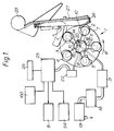
- the apparatus shown in Figures 1 to 3 is of substantially conventional form, particularly the construction of the head 1.
- the head 1 comprises five substantially equally angularly spaced suction spindles 2-6 rotatably mounted to a main support 7 which itself is rotatable under the control of a head motor 8.
- the support 7 is rotated in use in an anti-clockwise direction (as seen in Figure 1) while the suction spindles 2-6 are rotated in a clockwise direction.
- the gear assemblies for achieving these rotations are well known and will not be described further.
- the support 7 has a central bore 9 extending along its axis and communicating with a set of five ports 10 which communicate with respective suction spindles 2-6.
- the support 7 rotates about a central spindle 11 mounted within the bore 9 and shown in more detail in Figure 4.
- the central spindle 11 has a central bore 12 which is connected to an exhaust port 13 at one end which in turn is connected to a head valve 17, filter 18 and a vacuum pump 19. At its end level with the ports 10, the bore 12 terminates in port 16.
- Circumferentially spaced exhaust ports 14,15 are provided for communication with the ports 10. Between the ports 14,16 is a counting port 20 which communicates through a bore 21 in the central spindle 11 with a pressure transducer 22.
- the pressure transducer 22 is of conventional form and generates an electronic signal related to the sensed pressure. This signal is fed to a microprocessor 23 connected to control the head motor 8, a stack motor 24, and a display 25. The operation of the processor 23 will be described in more detail below.
- a stack of sheets 26 to be counted are loaded onto a support plate 27 pivoted to a shaft 28 ( Figure 2) the end of the stack nearest the shaft 28 being clamped in position by a clamp pin 29 mounted on an arm 30.
- the support plate 27 carrying a stack of sheets such as banknotes is brought to the position shown in Figures 1-3 and the processor 23 is then instructed to control the head motor 8 to start operation.
- the head motor 8 rotates the support 7 in an anti-clockwise direction thereby causing the spindles 2-6 to rotate in a clockwise direction and the first spindle 2 will arrive at the stack 26 ( Figure 1).
- a vacuum is supplied from the vacuum pump 19 to the port 16 so that as the port 10 associated with the spindle 2 approaches the position shown in Figure 1, the vacuum will be communicated through the port 16 and port 10 to the suction spindle 2.
- the suction spindle 2 will thus suck the topmost banknote against its outer periphery.
- the transducer 22 will see first a rise in vacuum, followed by a drop as the port 20 is connected to the exhaust port 14. This means that for each sheet the transducer will see a pulse, allowing the processor 23 to count these pulses and thereby count the number of sheets in the stack. This number is then displayed on the display 25 which is in the form of a LCD or the like.
- FIG. 5 illustrates a typical count sequence.
- the processor 23 activates the head motor 8 (step 41).
- the head 1 then begins to rotate and in this case, the first head 2 fails to pick the topmost sheet from the stack. Consequently, as shown in 42, only a small rise in vacuum level is measured. This rise does not exceed a predetermined threshold 43A and consequently no count pulse is generated within the processor 23.
- the next spindle successfully picks the topmost sheet thus causing a significant vacuum to be communicated into the counting port 20 so that the transducer 22 senses a drop in pressure which exceeds the predetermined threshold 43A. This is indicated at 43 in Figure 5.
- the processor 23 will generate a count pulse 44 which increments an internal count while the count to date is displayed on the display 25.
- the processor 23 is programmed to expect a count pulse within a certain time period and consequently if the time period passes without a count pulse being generated then the processor decides that the counting process should terminate and switches off the head motor at step 49.
- the time period will usually be long enough to permit two or three spindles to attempt to pick a note.
- the system determines that the end of a count cycle has taken place in a similar way although the predetermined period could be different, usually shorter, than the predetermined period at start-up.
- the predetermined period at start-up could correspond to the passage of three or four spindles past the stack while the predetermined period at the end of a count cycle could correspond to the passage of two or three spindles.
- FIG. 6 illustrates such an example in which the threshold level is indicated at 50.
- the vacuum signal drops with time due to the decrease in the pressure with which the stack is urged towards the spindles. This could result in a vacuum level due to a sheet not exceeding the threshold with the result that the sheet is not counted.
- the processor 23 can monitor and store in a store 100 the last N vacuum threshold levels which exceeded a threshold (N is typically eight) and were used to increment the count and can compute an average of those N levels from which a new threshold is calculated. For example, the processor could compute the average of the last three vacuum levels which exceeded a threshold and define the new threshold as being a proportion, for example 25-50%, of the new average.
- Figure 7 illustrates a threshold level 51 which is varied using this technique and it can be seen that later pulses although having a smaller absolute vacuum level magnitude, exceed the current threshold by similar proportions to the initial levels.
- the sheet stack is, as previously described, mounted on a support plate 27 which in turn is mounted on a feed shaft 28 for rotation therewith.
- the system for controlling the orientation of the shaft 28 is shown in more detail in Figure 8.
- the shaft 28 is rotatably mounted in bearings supported in housings 55 which are in turn mounted on a bracket 56.
- a shaft drive arm 57 non-rotatably mounted to the shaft 28 extends laterally away from the shaft 28 and is positioned adjacent a rack 58 rotatably mounted about the shaft 28.
- the teeth 59 of the rack 58 engage a drive pinion 60 which is connected to the stack motor 24 (not shown in Figure 8).
- the arm 57 is connected to the rack 58 via a tension spring 61.
- a stop pin 62 extends laterally from the rack 58 into an aperture 63 in the arm 57.
- the arm 57 also carries an adjustable screw 64.
- the shaft 28 also rotatably carries the clamp arm 30 which is connected in use to a torsion spring 65 to urge the clamp pin 29 against a stack held on the support plate.
- the stack of sheets to be counted is then loaded onto the plate 27 on which it is held by the clamp pin 29.
- the motor 24 is then activated to rotate the rack 58 in a clockwise direction moving the stop pin 62 away from the lower side of the aperture 63.
- the tension spring 61 will start to draw the arm 57 in a clockwise direction. This movement continues not only (at a relatively fast rate) to bring the stack of sheets initially into position but also (at a relatively slow rate) during the counting operation with the tension spring exerting a reasonably uniform feed load on the sheets.
- the speed of the motor 24 is controlled by an over current limiter.
- pin 62 drives up against the shaft drive arm so increasing the load on the drive motor.
- This increase in load is measured by a current limiting device which slows down the drive motor.
- a substantially constant load is imparted on the stack of sheets throughout the counting operation.
- the operation of this mechanism to count sheets may be improved with the addition of a damper (66) acting on the feedshaft (28).
Landscapes
- Physics & Mathematics (AREA)
- General Physics & Mathematics (AREA)
- Engineering & Computer Science (AREA)
- Theoretical Computer Science (AREA)
- Controlling Sheets Or Webs (AREA)
- Sheets, Magazines, And Separation Thereof (AREA)
- Pile Receivers (AREA)
Description
- It is already known to provide apparatus for counting sheets held in a stack, the apparatus comprising a set of rotatably mounted suction spindles mounted for movement past a stack of sheets to be counted, vacuum supply means connected to the spindles, whereby as a suction spindle passes the stack, a vacuum is supplied to the spindle so that the topmost sheet is deflected from its initial position; and monitoring means for monitoring the number of deflected sheets. Such apparatus is hereinafter referred to as of the kind described and is commonly referred to as a "spindle counter".
- Most spindle counters require a minimum pressure (vacuum) to be maintained within the system with the counting being achieved by means of external electromagnetic/photoelectric sensors which operate independently of the vacuum system provided the minimum pressure is maintained. An example is described in GB-A-2041888.
- Another approach is to detect changes in the pressure or vacuum supplied to the spindles. An increase in vacuum (decrease in pressure) corresponds to a sheet being deflected and this change can be used to implement a count. Examples of such spindle counters are described in GB-A-2238411, GB-A-2238895, GB-A-2137000 and GB-A-1530652.
- In some of these known spindle counters, for example those described in GB-A-2238411 and GB-A-2238895, it is necessary to index the spindles to a known position prior to the start of the count process. This is undesirable.
- A further problem with systems such as that described in GB-A-2238895 is that if a spindle fails to deflect a note during a count process, the system will stop. This leads to problems in that the whole process has to be restarted.
- The invention relates to an apparatus and method of counting sheets as set out in claims 1 and 5.
- In accordance with one embodiment of the present invention, we provide apparatus of the kind described wherein the monitoring means monitors the degree of vacuum within the suction spindle passing the stack whereby the monitoring means increments a count on each occasion when the monitored vacuum exceeds a predetermined threshold, the monitoring means terminating the count process when a predetermined period is exceeded without the vacuum exceeding the predetermined threshold, the predetermined period corresponding to the passage of at least two spindles past the stack without deflecting a sheet.
- In accordance with a second embodiment of the present invention, a method of counting sheets using apparatus comprising a set of rotatably mounted suction spindles mounted for movement past a stack of sheets to be counted, whereby as a suction spindle passes the stack, a vacuum is supplied to the spindle so that the topmost sheet is deflected from its initial position comprises monitoring the degree of vacuum within the suction spindle passing the stack and incrementing a count on each occasion when the vacuum exceeds a predetermined threshold; and terminating the count process when a predetermined period is exceeded without the vacuum exceeding the predetermined threshold, the predetermined period corresponding to the passage of at least two spindles past the stack of sheets without deflecting a sheet.
- The apparatus and method according to the invention overcome the problems mentioned above by permitting at least one spindle to pass the stack without deflecting a sheet and continuing the count process. In particular, the count process will only be terminated if at least two spindles have passed the stack of sheets without deflecting a sheet. The invention also has some advantage at start-up in that it can permit a predetermined number (for example 5) of spindles to pass the stack without deflecting a sheet. If sheets start to be deflected during this period then these will be counted due to the drop in pressure but if all the predetermined number of spindles pass the stack without deflecting a sheet then the monitoring means will indicate this as being the end of a count process.
- The predetermined period may be the same throughout a count process or the period may be different at the start of a count process than during the remainder of the process.
- A further advantage of the invention is that it provides significant improvements in the ability to count stiff or otherwise difficult to pick sheets.
- Preferably, the apparatus further comprises a central porting member about which the spindles rotate, the central porting member having a vacuum supply port connected to the vacuum supply means, and a vacuum sensing port connected to the monitoring means, the vacuum supply and sensing ports being positioned such that during rotation of a spindle past the sheet stack, a spindle vacuum port will initially communicate only with the vacuum supply port, then with both the vacuum supply and sensing ports, and finally with only the vacuum sensing port.
- The monitoring means can also be used for diagnostic purposes. Thus, when the spindles are stationary and the vacuum port of the spindle is covered, the application of a vacuum can be sensed by the monitoring means to provide an absolute indication of the vacuum level. This can then be used to adjust the vacuum level to a desired strength.
- Alternatively and in a particularly preferred arrangement, the pressure can be sensed under dynamic conditions when the apparatus is operating and deflecting sheets. When a sheet is in the process of being deflected, vacuum and pressure signals for that sheet can be sensed and stored in a data store such as a RAM device and retrieved at a later stage to indicate how the apparatus performed. Numerical calculations may also be performed using the data recorded to provide derivative information such as the number of sheets which the spindles failed to pick the first time or to provide a warning that cleaning is required as indicated by a rise in vacuum level when no sheets are deflected.
- Known apparatus of the kind described, where the pressure or vacuum within the suction spindle passing the stack is monitored to determine the number of deflected sheets, relies on providing a threshold level against which the monitored pressure or vacuum is compared.
- We have found that during a count, the peak vacuum level can reduce for various reasons such as porosity of the notes, and the reduction in force with which the stack of sheets is fed towards the suction spindles since this is normally under the control of an uncoiling spring or tension spring. In extreme cases this peak vacuum level could drop below the initially preset threshold causing a count to be aborted.
- Preferably, therefore, the monitoring means adapts the threshold during a count process by regularly resetting the threshold at a preset proportion of a rolling average of a predetermined number of previous vacuum levels detected as indicating the deflection of a sheet.
- This overcomes the problems outlined above by adapting the threshold during the count process. Typically, the most recent eight pressure levels are averaged and a proportion such as 25-50% of this average used to constitute the threshold with which the next pressure level is compared. It should be noted, of course, that it is only the preceding pressure levels which exceed thresholds which are used in computing the rolling average. If, for example, a suction spindle does not deflect a sheet for any reason, the detected (high) pressure level is not used to compute the rolling average.
- It will be understood that all embodiments of the invention are suitable for handling and counting sheets of various types but they are particularly suitable for use with banknotes.
- An example of a spindle counter according to the apparatus and method of the invention will now be described with reference to the accompanying drawings, in which:-
- Figure 1 is a schematic diagram of the apparatus with the head in a first position;
- Figure 2 is a view similar to Figure 1 (with parts omitted) with the head in a second position;
- Figure 3 is a view similar to Figure 2 with the head in a third position;
- Figure 4 illustrates the centre spindle in more detail;
- Figure 5 illustrates a typical count sequence;
- Figure 6 illustrates the variation of sensed pressure against a constant threshold;
- Figure 7 illustrates the variation of sensed pressure against an adaptive threshold; and,
- Figure 8 is a schematic, perspective view of part of the sheet stack control system.
-
- The apparatus shown in Figures 1 to 3 is of substantially conventional form, particularly the construction of the head 1. The head 1 comprises five substantially equally angularly spaced suction spindles 2-6 rotatably mounted to a main support 7 which itself is rotatable under the control of a
head motor 8. The support 7 is rotated in use in an anti-clockwise direction (as seen in Figure 1) while the suction spindles 2-6 are rotated in a clockwise direction. The gear assemblies for achieving these rotations are well known and will not be described further. - The support 7 has a central bore 9 extending along its axis and communicating with a set of five
ports 10 which communicate with respective suction spindles 2-6. The support 7 rotates about acentral spindle 11 mounted within the bore 9 and shown in more detail in Figure 4. Thecentral spindle 11 has acentral bore 12 which is connected to an exhaust port 13 at one end which in turn is connected to ahead valve 17,filter 18 and avacuum pump 19. At its end level with theports 10, thebore 12 terminates inport 16. Circumferentially spacedexhaust ports ports 10. Between theports port 20 which communicates through abore 21 in thecentral spindle 11 with apressure transducer 22. - The
pressure transducer 22 is of conventional form and generates an electronic signal related to the sensed pressure. This signal is fed to amicroprocessor 23 connected to control thehead motor 8, astack motor 24, and adisplay 25. The operation of theprocessor 23 will be described in more detail below. - A stack of
sheets 26 to be counted are loaded onto asupport plate 27 pivoted to a shaft 28 (Figure 2) the end of the stack nearest theshaft 28 being clamped in position by aclamp pin 29 mounted on anarm 30. - In operation, the
support plate 27 carrying a stack of sheets such as banknotes is brought to the position shown in Figures 1-3 and theprocessor 23 is then instructed to control thehead motor 8 to start operation. Thehead motor 8 rotates the support 7 in an anti-clockwise direction thereby causing the spindles 2-6 to rotate in a clockwise direction and thefirst spindle 2 will arrive at the stack 26 (Figure 1). A vacuum is supplied from thevacuum pump 19 to theport 16 so that as theport 10 associated with thespindle 2 approaches the position shown in Figure 1, the vacuum will be communicated through theport 16 andport 10 to thesuction spindle 2. Thesuction spindle 2 will thus suck the topmost banknote against its outer periphery. Further rotation of the support 7 andspindle 2 draws the topmost banknote (shown at 31 in Figure 2) away from the stack. As thespindle 2 continues to rotate, theport 10 associated with thespindle 2 will move round to overlap the vacuum and countingports transducer 22 via thebore 21 so that the transducer sees the high level of vacuum. As the head 1 continues to rotate, theport 10 becomes disconnected from thevacuum port 16 remaining connected only to the counting port 20 (Figure 2). Shortly after this, as the head continues to rotate, theport 10 associated withspindle 2 will overlap both the countingport 20 andexhaust port 14. This allows the vacuum present in the sealed spindle to be opened to the atmosphere viaports port 20 to the atmosphere. At this time the sheet held by thespindle 2 is released due to the loss of vacuum and further rotation brings theport 10 solely into line with port 14 (Figure 3). As the head 1 rotates further, the sequence repeats for the next spindle 6 and so on. - Due to the overlapping action of the counting
port 20 with the vacuum andexhaust ports transducer 22 will see first a rise in vacuum, followed by a drop as theport 20 is connected to theexhaust port 14. This means that for each sheet the transducer will see a pulse, allowing theprocessor 23 to count these pulses and thereby count the number of sheets in the stack. This number is then displayed on thedisplay 25 which is in the form of a LCD or the like. - Figure 5 illustrates a typical count sequence. Initially, the
processor 23 activates the head motor 8 (step 41). The head 1 then begins to rotate and in this case, thefirst head 2 fails to pick the topmost sheet from the stack. Consequently, as shown in 42, only a small rise in vacuum level is measured. This rise does not exceed apredetermined threshold 43A and consequently no count pulse is generated within theprocessor 23. The next spindle successfully picks the topmost sheet thus causing a significant vacuum to be communicated into the countingport 20 so that thetransducer 22 senses a drop in pressure which exceeds thepredetermined threshold 43A. This is indicated at 43 in Figure 5. As soon as the sensed vacuum exceeds the threshold, theprocessor 23 will generate a count pulse 44 which increments an internal count while the count to date is displayed on thedisplay 25. - This process continues as shown in Figure 5 but where a spindle fails to pick a sheet, as at 45, no count pulse is generated. After the
failure 45, the next spindle successfully picks the note so that counting continues until the last sheet is picked as shown at 46. After this, two further spindles will attempt to pick sheets from the stack but since no sheets will be picked, only small changes in vacuum level will be sensed as shown at 47 and 48. - The
processor 23 is programmed to expect a count pulse within a certain time period and consequently if the time period passes without a count pulse being generated then the processor decides that the counting process should terminate and switches off the head motor atstep 49. The time period will usually be long enough to permit two or three spindles to attempt to pick a note. - It will be seen from this description that there is no need to position the head 1 at a particular index position prior to commencing the count process. Counting is automatically carried out and although it is likely that for an initial period no sheets will be picked as the sheets are being fed towards the spindles on the
support plate 27, theprocessor 22 can accommodate this by not incrementing the count. Providing a note is counted before an initial, predetermined period expires then the process will continue. If for some reason no sheet is detected within that predetermined period then thehead motor 8 will be stopped. - The system determines that the end of a count cycle has taken place in a similar way although the predetermined period could be different, usually shorter, than the predetermined period at start-up. For example, the predetermined period at start-up could correspond to the passage of three or four spindles past the stack while the predetermined period at the end of a count cycle could correspond to the passage of two or three spindles.
- In the example just described it has been assumed that the vacuum level threshold is constant throughout the counting process. Figure 6 illustrates such an example in which the threshold level is indicated at 50. As can be seen, the vacuum signal drops with time due to the decrease in the pressure with which the stack is urged towards the spindles. This could result in a vacuum level due to a sheet not exceeding the threshold with the result that the sheet is not counted.
- To overcome this problem, the
processor 23 can monitor and store in astore 100 the last N vacuum threshold levels which exceeded a threshold (N is typically eight) and were used to increment the count and can compute an average of those N levels from which a new threshold is calculated. For example, the processor could compute the average of the last three vacuum levels which exceeded a threshold and define the new threshold as being a proportion, for example 25-50%, of the new average. Figure 7 illustrates athreshold level 51 which is varied using this technique and it can be seen that later pulses although having a smaller absolute vacuum level magnitude, exceed the current threshold by similar proportions to the initial levels. - The sheet stack is, as previously described, mounted on a
support plate 27 which in turn is mounted on afeed shaft 28 for rotation therewith. The system for controlling the orientation of theshaft 28 is shown in more detail in Figure 8. Theshaft 28 is rotatably mounted in bearings supported inhousings 55 which are in turn mounted on abracket 56. Ashaft drive arm 57 non-rotatably mounted to theshaft 28 extends laterally away from theshaft 28 and is positioned adjacent arack 58 rotatably mounted about theshaft 28. Theteeth 59 of therack 58 engage adrive pinion 60 which is connected to the stack motor 24 (not shown in Figure 8). Thearm 57 is connected to therack 58 via atension spring 61. - A
stop pin 62 extends laterally from therack 58 into anaperture 63 in thearm 57. Thearm 57 also carries anadjustable screw 64. - The
shaft 28 also rotatably carries theclamp arm 30 which is connected in use to atorsion spring 65 to urge theclamp pin 29 against a stack held on the support plate. - The operation of the system shown in Figure 8 will now be described. Consider the position in which the
plate 27 is in its forward position as shown generally in Figures 1 to 3. Following the counting of a batch of sheets, themotor 24 is activated to rotate therack 58 in an anti-clockwise direction (as seen in Figure 8) which causes thestop pin 62 to move relative to theaperture 63 in thearm 57 and until the pin engages the lower side of the aperture whereupon thearm 57 is also rotated anti-clockwise until theadjustor screw 64 locates on thebrackets 56. When this occurs, a current over limit device (not shown) stops the motor. - The stack of sheets to be counted is then loaded onto the
plate 27 on which it is held by theclamp pin 29. Themotor 24 is then activated to rotate therack 58 in a clockwise direction moving thestop pin 62 away from the lower side of theaperture 63. Once thepin 63 reaches substantially the position shown in Figure 8, thetension spring 61 will start to draw thearm 57 in a clockwise direction. This movement continues not only (at a relatively fast rate) to bring the stack of sheets initially into position but also (at a relatively slow rate) during the counting operation with the tension spring exerting a reasonably uniform feed load on the sheets. The speed of themotor 24 is controlled by an over current limiter. Thus, if the note feed is too fast, then pin 62 drives up against the shaft drive arm so increasing the load on the drive motor. This increase in load is measured by a current limiting device which slows down the drive motor. In this way, a substantially constant load is imparted on the stack of sheets throughout the counting operation. The operation of this mechanism to count sheets may be improved with the addition of a damper (66) acting on the feedshaft (28).
Claims (11)
- Sheet counting apparatus comprising a set of rotatably mounted suction spindles (2-6) mounted for movement past a stack of sheets (26) to be counted, vacuum supply means (19) connected to the spindles whereby as a suction spindle passes the stack, a vacuum is supplied to the spindle so that the topmost sheet is deflected from its initial position; and monitoring means (22,23) for monitoring the number of deflected sheets, wherein the monitoring means monitors the degree of vacuum within the suction spindle passing the stack whereby the monitoring means increments a count on each occasion when the monitored vacuum exceeds a predetermined threshold, the monitoring means terminating the count process when a predetermined period is exceeded without the vacuum exceeding the predetermined threshold, characterised in that the predetermined period corresponds to the passage of at least two spindles past the stack of sheets without deflecting a sheet.
- Apparatus according to claim 1, wherein the predetermined period is the same throughout a count process.
- Apparatus according to claim 1 or claim 2, further comprising a central porting member (11) about which the spindles (2-6) rotate, the central porting member having a vacuum supply port (16) connected to the vacuum supply means (19), and a vacuum sensing port (20) connected to the monitoring means (22,23), the vacuum supply and sensing ports (16,20) being positioned such that during rotation of a spindle past the sheet stack, a spindle vacuum port (10) will initially communicate only with the vacuum supply port, then with both the vacuum supply and sensing ports, and finally with only the vacuum sensing port.
- Apparatus according to any of claims 1 to 3, further comprising a data store (100), and wherein the monitoring means (23) is adapted to determine and store in the data store the monitored pressure when a sheet is deflected.
- A method of counting sheets using apparatus comprising a set of rotatably mounted suction spindles (2-6) mounted for movement past a stack of sheets (26) to be counted, whereby as a suction spindle passes the stack, a vacuum is supplied to the spindle so that the topmost sheet is deflected from its initial position, the method comprising monitoring the degree of vacuum within the suction spindle passing the stack and incrementing a count on each occasion when the vacuum exceeds a predetermined threshold; and terminating the count process when a predetermined period is exceeded without the vacuum exceeding the predetermined threshold, characterised in that the predetermined period corresponds to the passage of at least two spindles past the stack of sheets without deflecting a sheet.
- A method according to claim 5, wherein the predetermined period is the same throughout a count process.
- A method according to claim 5 or claim 6, further comprising monitoring the absolute pressure in the spindle when a sheet is deflected and storing a value representing the monitored pressure.
- Sheet counting apparatus according to any of claims 1 to 4, wherein the monitoring means adapts the threshold during a count process by regularly resetting the threshold at a preset proportion of a rolling average of a predetermined number of previous vacuum levels detected as indicating the deflection of a sheet.
- Apparatus according to claim 8, wherein the most recent 8 vacuum levels are averaged.
- A method of counting sheets according to any of claims 5 to 7, further comprising adapting the threshold during the count process by regularly resetting the threshold at a proportion of a rolling average of a predetermined number of previous vacuum levels detected as indicating the deflection of a sheet.
- A method according to claim 10, wherein the most recent 8 vacuum levels are averaged.
Priority Applications (2)
| Application Number | Priority Date | Filing Date | Title |
|---|---|---|---|
| EP99110931A EP0942394B1 (en) | 1993-02-18 | 1994-02-15 | Counting stacked sheets |
| EP99110930A EP0942393B1 (en) | 1993-02-18 | 1994-02-15 | Counting stacked sheets |
Applications Claiming Priority (2)
| Application Number | Priority Date | Filing Date | Title |
|---|---|---|---|
| GB939303222A GB9303222D0 (en) | 1993-02-18 | 1993-02-18 | Provements relating to sheet processing |
| GB9303222 | 1993-02-18 |
Related Child Applications (2)
| Application Number | Title | Priority Date | Filing Date |
|---|---|---|---|
| EP99110930A Division EP0942393B1 (en) | 1993-02-18 | 1994-02-15 | Counting stacked sheets |
| EP99110931A Division EP0942394B1 (en) | 1993-02-18 | 1994-02-15 | Counting stacked sheets |
Publications (3)
| Publication Number | Publication Date |
|---|---|
| EP0616300A2 EP0616300A2 (en) | 1994-09-21 |
| EP0616300A3 EP0616300A3 (en) | 1994-12-21 |
| EP0616300B1 true EP0616300B1 (en) | 2000-05-03 |
Family
ID=10730615
Family Applications (3)
| Application Number | Title | Priority Date | Filing Date |
|---|---|---|---|
| EP99110930A Expired - Lifetime EP0942393B1 (en) | 1993-02-18 | 1994-02-15 | Counting stacked sheets |
| EP99110931A Expired - Lifetime EP0942394B1 (en) | 1993-02-18 | 1994-02-15 | Counting stacked sheets |
| EP94301070A Expired - Lifetime EP0616300B1 (en) | 1993-02-18 | 1994-02-15 | Apparatus and method for counting and stacking sheets |
Family Applications Before (2)
| Application Number | Title | Priority Date | Filing Date |
|---|---|---|---|
| EP99110930A Expired - Lifetime EP0942393B1 (en) | 1993-02-18 | 1994-02-15 | Counting stacked sheets |
| EP99110931A Expired - Lifetime EP0942394B1 (en) | 1993-02-18 | 1994-02-15 | Counting stacked sheets |
Country Status (6)
| Country | Link |
|---|---|
| US (1) | US5454017A (en) |
| EP (3) | EP0942393B1 (en) |
| DE (3) | DE69432533D1 (en) |
| ES (1) | ES2148282T3 (en) |
| GB (1) | GB9303222D0 (en) |
| PT (1) | PT616300E (en) |
Cited By (1)
| Publication number | Priority date | Publication date | Assignee | Title |
|---|---|---|---|---|
| DE10019692A1 (en) * | 2000-04-20 | 2001-10-25 | Daniel Holoch | Device for supplying/exchanging sheets in loose sheet collection has containers holding sheets in vertical position, vertically movable conveyor and vacuum sheet counting machine |
Families Citing this family (4)
| Publication number | Priority date | Publication date | Assignee | Title |
|---|---|---|---|---|
| GB9504357D0 (en) * | 1995-03-03 | 1995-04-26 | Portals Eng Ltd | Setting-up sheet counters |
| GB9621691D0 (en) | 1996-10-17 | 1996-12-11 | De La Rue Systems Ltd | Sheet counting apparatus |
| GB9907738D0 (en) | 1999-04-01 | 1999-05-26 | Rue De Int Ltd | Sheet cutting apparatus and method |
| KR20010054960A (en) * | 1999-12-08 | 2001-07-02 | 한연섭 | Vacuum suction type banknotecounter |
Family Cites Families (12)
| Publication number | Priority date | Publication date | Assignee | Title |
|---|---|---|---|---|
| US3962564A (en) * | 1974-09-19 | 1976-06-08 | Vacuumatic Limited | Apparatus for counting a stack of sheets |
| JPS5756109B2 (en) * | 1975-01-30 | 1982-11-27 | ||
| JPS5847069B2 (en) * | 1978-10-31 | 1983-10-20 | ロ−レルバンクマシン株式会社 | Paper sheet holding device for paper sheet counting machine |
| JPS5828633B2 (en) * | 1978-12-22 | 1983-06-17 | ロ−レルバンクマシン株式会社 | Paper sheet bundle holding device in paper sheet counting machine |
| FR2448751A1 (en) * | 1979-02-09 | 1980-09-05 | Etude Const App Prec | DEVICE FOR COUNTING AND DISPENSING SHEETS |
| SE443885B (en) * | 1979-07-13 | 1986-03-10 | De La Rue Syst | DEVICE FOR CALCULATING THE NUMBER OF SHEETS IN A STACK |
| US4490800A (en) * | 1981-12-14 | 1984-12-25 | Powers Manufacturing, Inc. | Dual head gauger apparatus with automatic adjustment for pressure variation |
| JPS5932087A (en) * | 1982-08-14 | 1984-02-21 | Laurel Bank Mach Co Ltd | Paper sheet counter |
| GB2137000A (en) * | 1983-03-21 | 1984-09-26 | De La Rue Syst | Sheet counting apparatus |
| JPH079675B2 (en) * | 1987-04-30 | 1995-02-01 | ロ−レルバンクマシン株式会社 | Double feed detecting device in bill counting machine |
| US4974237A (en) * | 1989-03-13 | 1990-11-27 | Hall Processing Systems | Contact type paper counter |
| CH683878A5 (en) * | 1989-11-10 | 1994-05-31 | Laurel Bank Machine Co | Machines for counting sheets. |
-
1993
- 1993-02-18 GB GB939303222A patent/GB9303222D0/en active Pending
-
1994
- 1994-02-15 EP EP99110930A patent/EP0942393B1/en not_active Expired - Lifetime
- 1994-02-15 DE DE69432533T patent/DE69432533D1/en not_active Expired - Lifetime
- 1994-02-15 ES ES94301070T patent/ES2148282T3/en not_active Expired - Lifetime
- 1994-02-15 EP EP99110931A patent/EP0942394B1/en not_active Expired - Lifetime
- 1994-02-15 PT PT94301070T patent/PT616300E/en unknown
- 1994-02-15 DE DE69424213T patent/DE69424213T2/en not_active Expired - Fee Related
- 1994-02-15 EP EP94301070A patent/EP0616300B1/en not_active Expired - Lifetime
- 1994-02-15 DE DE69434006T patent/DE69434006T2/en not_active Expired - Fee Related
- 1994-02-17 US US08/198,154 patent/US5454017A/en not_active Expired - Fee Related
Cited By (2)
| Publication number | Priority date | Publication date | Assignee | Title |
|---|---|---|---|---|
| DE10019692A1 (en) * | 2000-04-20 | 2001-10-25 | Daniel Holoch | Device for supplying/exchanging sheets in loose sheet collection has containers holding sheets in vertical position, vertically movable conveyor and vacuum sheet counting machine |
| DE10019692B4 (en) * | 2000-04-20 | 2005-09-29 | Daniel Holoch | Device for supplementing or replacing leaves in loose-leaf collections |
Also Published As
| Publication number | Publication date |
|---|---|
| EP0942393B1 (en) | 2003-04-16 |
| DE69424213D1 (en) | 2000-06-08 |
| EP0616300A3 (en) | 1994-12-21 |
| US5454017A (en) | 1995-09-26 |
| GB9303222D0 (en) | 1993-04-07 |
| EP0942394A3 (en) | 2000-09-20 |
| ES2148282T3 (en) | 2000-10-16 |
| EP0942393A2 (en) | 1999-09-15 |
| EP0942394A2 (en) | 1999-09-15 |
| PT616300E (en) | 2000-10-31 |
| DE69434006D1 (en) | 2004-10-21 |
| DE69432533D1 (en) | 2003-05-22 |
| EP0942393A3 (en) | 2000-09-20 |
| DE69424213T2 (en) | 2000-09-07 |
| DE69434006T2 (en) | 2005-01-27 |
| EP0616300A2 (en) | 1994-09-21 |
| EP0942394B1 (en) | 2004-09-15 |
Similar Documents
| Publication | Publication Date | Title |
|---|---|---|
| US5435540A (en) | Apparatus and method for sheet feeding and separating using retard roll relief/enhancement | |
| AU706031B2 (en) | Sheet feeding apparatus and method | |
| EP2922038B1 (en) | Banknote temporary storage module and reel rotating speed control method thereof | |
| EP0389745A2 (en) | Method and apparatus for controlling a multiple delivery collator in response to a downstream fault condition | |
| US8915460B2 (en) | Device for feeding a quasi-endless material web | |
| EP0942393B1 (en) | Counting stacked sheets | |
| EP0470273A1 (en) | Method and apparatus for winding a yarn | |
| CN1152901A (en) | Control method of rotary transmission device of winding machine | |
| US20020140159A1 (en) | Method and system for providing sheet stack level control | |
| WO1995018762A1 (en) | Web reel brake control system | |
| EP0417869B1 (en) | Collation error indication system for collator | |
| JP4377113B2 (en) | Method and apparatus for controlling suction ventilation in a lint suction device of a spinning machine | |
| US6530525B1 (en) | Sheet counting apparatus and method | |
| US5929346A (en) | Apparatus for detecting abnormalities in a work holder | |
| EP0416280A2 (en) | Pick mechanism for sheet feeding apparatus | |
| JPH07102908B2 (en) | Automatic paper feeder | |
| EP0990721A1 (en) | Multiple twister | |
| EP1015194B1 (en) | Method for die jam protection/anticipation and correction | |
| JPS6342942A (en) | Detection of warp yarn feed-out abnormality in loom | |
| EP0477782A2 (en) | Fuzzy control device to feed and adjust sheets of paper | |
| JPS6322435A (en) | Paper handling equipment | |
| JPH0967036A (en) | Separating roller adjusting device and adjusting method | |
| EP1391983B1 (en) | Method for detecting the stall of the motor of the pre-feeder of weft pre-measurer in weaving looms | |
| EP0932881A1 (en) | Sheet counting apparatus and method | |
| JPH04153147A (en) | Sheet supply device |
Legal Events
| Date | Code | Title | Description |
|---|---|---|---|
| PUAI | Public reference made under article 153(3) epc to a published international application that has entered the european phase |
Free format text: ORIGINAL CODE: 0009012 |
|
| AK | Designated contracting states |
Kind code of ref document: A2 Designated state(s): BE CH DE ES FR GB IT LI NL PT SE |
|
| PUAL | Search report despatched |
Free format text: ORIGINAL CODE: 0009013 |
|
| AK | Designated contracting states |
Kind code of ref document: A3 Designated state(s): BE CH DE ES FR GB IT LI NL PT SE |
|
| 17P | Request for examination filed |
Effective date: 19950426 |
|
| 17Q | First examination report despatched |
Effective date: 19961107 |
|
| RAP1 | Party data changed (applicant data changed or rights of an application transferred) |
Owner name: DE LA RUE INTERNATIONAL LIMITED |
|
| GRAG | Despatch of communication of intention to grant |
Free format text: ORIGINAL CODE: EPIDOS AGRA |
|
| RAP1 | Party data changed (applicant data changed or rights of an application transferred) |
Owner name: DE LA RUE INTERNATIONAL LIMITED |
|
| GRAG | Despatch of communication of intention to grant |
Free format text: ORIGINAL CODE: EPIDOS AGRA |
|
| GRAH | Despatch of communication of intention to grant a patent |
Free format text: ORIGINAL CODE: EPIDOS IGRA |
|
| GRAH | Despatch of communication of intention to grant a patent |
Free format text: ORIGINAL CODE: EPIDOS IGRA |
|
| GRAA | (expected) grant |
Free format text: ORIGINAL CODE: 0009210 |
|
| AK | Designated contracting states |
Kind code of ref document: B1 Designated state(s): BE CH DE ES FR GB IT LI NL PT SE |
|
| REG | Reference to a national code |
Ref country code: CH Ref legal event code: NV Representative=s name: ISLER & PEDRAZZINI AG Ref country code: CH Ref legal event code: EP |
|
| REF | Corresponds to: |
Ref document number: 69424213 Country of ref document: DE Date of ref document: 20000608 |
|
| ITF | It: translation for a ep patent filed | ||
| ET | Fr: translation filed | ||
| REG | Reference to a national code |
Ref country code: ES Ref legal event code: FG2A Ref document number: 2148282 Country of ref document: ES Kind code of ref document: T3 |
|
| REG | Reference to a national code |
Ref country code: PT Ref legal event code: SC4A Free format text: AVAILABILITY OF NATIONAL TRANSLATION Effective date: 20000731 |
|
| PLBE | No opposition filed within time limit |
Free format text: ORIGINAL CODE: 0009261 |
|
| STAA | Information on the status of an ep patent application or granted ep patent |
Free format text: STATUS: NO OPPOSITION FILED WITHIN TIME LIMIT |
|
| 26N | No opposition filed | ||
| REG | Reference to a national code |
Ref country code: GB Ref legal event code: IF02 |
|
| PGFP | Annual fee paid to national office [announced via postgrant information from national office to epo] |
Ref country code: SE Payment date: 20030205 Year of fee payment: 10 |
|
| PGFP | Annual fee paid to national office [announced via postgrant information from national office to epo] |
Ref country code: PT Payment date: 20030210 Year of fee payment: 10 Ref country code: FR Payment date: 20030210 Year of fee payment: 10 |
|
| PGFP | Annual fee paid to national office [announced via postgrant information from national office to epo] |
Ref country code: GB Payment date: 20030212 Year of fee payment: 10 |
|
| PGFP | Annual fee paid to national office [announced via postgrant information from national office to epo] |
Ref country code: CH Payment date: 20030214 Year of fee payment: 10 |
|
| PGFP | Annual fee paid to national office [announced via postgrant information from national office to epo] |
Ref country code: NL Payment date: 20030226 Year of fee payment: 10 Ref country code: ES Payment date: 20030226 Year of fee payment: 10 |
|
| PGFP | Annual fee paid to national office [announced via postgrant information from national office to epo] |
Ref country code: DE Payment date: 20030227 Year of fee payment: 10 |
|
| PGFP | Annual fee paid to national office [announced via postgrant information from national office to epo] |
Ref country code: BE Payment date: 20030425 Year of fee payment: 10 |
|
| PG25 | Lapsed in a contracting state [announced via postgrant information from national office to epo] |
Ref country code: GB Free format text: LAPSE BECAUSE OF NON-PAYMENT OF DUE FEES Effective date: 20040215 |
|
| PG25 | Lapsed in a contracting state [announced via postgrant information from national office to epo] |
Ref country code: SE Free format text: LAPSE BECAUSE OF NON-PAYMENT OF DUE FEES Effective date: 20040216 Ref country code: ES Free format text: LAPSE BECAUSE OF NON-PAYMENT OF DUE FEES Effective date: 20040216 |
|
| PG25 | Lapsed in a contracting state [announced via postgrant information from national office to epo] |
Ref country code: BE Free format text: LAPSE BECAUSE OF NON-PAYMENT OF DUE FEES Effective date: 20040228 |
|
| PG25 | Lapsed in a contracting state [announced via postgrant information from national office to epo] |
Ref country code: LI Free format text: LAPSE BECAUSE OF NON-PAYMENT OF DUE FEES Effective date: 20040229 Ref country code: CH Free format text: LAPSE BECAUSE OF NON-PAYMENT OF DUE FEES Effective date: 20040229 |
|
| BERE | Be: lapsed |
Owner name: *DE LA RUE INTERNATIONAL LTD Effective date: 20040228 |
|
| PG25 | Lapsed in a contracting state [announced via postgrant information from national office to epo] |
Ref country code: PT Free format text: LAPSE BECAUSE OF NON-PAYMENT OF DUE FEES Effective date: 20040831 |
|
| PG25 | Lapsed in a contracting state [announced via postgrant information from national office to epo] |
Ref country code: NL Free format text: LAPSE BECAUSE OF NON-PAYMENT OF DUE FEES Effective date: 20040901 Ref country code: DE Free format text: LAPSE BECAUSE OF NON-PAYMENT OF DUE FEES Effective date: 20040901 |
|
| EUG | Se: european patent has lapsed | ||
| GBPC | Gb: european patent ceased through non-payment of renewal fee |
Effective date: 20040215 |
|
| REG | Reference to a national code |
Ref country code: CH Ref legal event code: PL |
|
| PG25 | Lapsed in a contracting state [announced via postgrant information from national office to epo] |
Ref country code: FR Free format text: LAPSE BECAUSE OF NON-PAYMENT OF DUE FEES Effective date: 20041029 |
|
| NLV4 | Nl: lapsed or anulled due to non-payment of the annual fee |
Effective date: 20040901 |
|
| REG | Reference to a national code |
Ref country code: FR Ref legal event code: ST |
|
| PG25 | Lapsed in a contracting state [announced via postgrant information from national office to epo] |
Ref country code: IT Free format text: LAPSE BECAUSE OF NON-PAYMENT OF DUE FEES;WARNING: LAPSES OF ITALIAN PATENTS WITH EFFECTIVE DATE BEFORE 2007 MAY HAVE OCCURRED AT ANY TIME BEFORE 2007. THE CORRECT EFFECTIVE DATE MAY BE DIFFERENT FROM THE ONE RECORDED. Effective date: 20050215 |
|
| REG | Reference to a national code |
Ref country code: ES Ref legal event code: FD2A Effective date: 20040216 |