EP0616230A1 - Homogeneous field magnet with pole plate spaced by correction air-gap for each pole shoe - Google Patents
Homogeneous field magnet with pole plate spaced by correction air-gap for each pole shoe Download PDFInfo
- Publication number
- EP0616230A1 EP0616230A1 EP94103114A EP94103114A EP0616230A1 EP 0616230 A1 EP0616230 A1 EP 0616230A1 EP 94103114 A EP94103114 A EP 94103114A EP 94103114 A EP94103114 A EP 94103114A EP 0616230 A1 EP0616230 A1 EP 0616230A1
- Authority
- EP
- European Patent Office
- Prior art keywords
- pole plate
- pole
- facing
- plate elements
- gap
- Prior art date
- Legal status (The legal status is an assumption and is not a legal conclusion. Google has not performed a legal analysis and makes no representation as to the accuracy of the status listed.)
- Granted
Links
Images

Classifications
-
- H—ELECTRICITY
- H01—ELECTRIC ELEMENTS
- H01F—MAGNETS; INDUCTANCES; TRANSFORMERS; SELECTION OF MATERIALS FOR THEIR MAGNETIC PROPERTIES
- H01F7/00—Magnets
- H01F7/02—Permanent magnets [PM]
- H01F7/0273—Magnetic circuits with PM for magnetic field generation
- H01F7/0278—Magnetic circuits with PM for magnetic field generation for generating uniform fields, focusing, deflecting electrically charged particles
-
- G—PHYSICS
- G01—MEASURING; TESTING
- G01R—MEASURING ELECTRIC VARIABLES; MEASURING MAGNETIC VARIABLES
- G01R33/00—Arrangements or instruments for measuring magnetic variables
- G01R33/20—Arrangements or instruments for measuring magnetic variables involving magnetic resonance
- G01R33/28—Details of apparatus provided for in groups G01R33/44 - G01R33/64
- G01R33/38—Systems for generation, homogenisation or stabilisation of the main or gradient magnetic field
- G01R33/383—Systems for generation, homogenisation or stabilisation of the main or gradient magnetic field using permanent magnets
Definitions
- the invention relates to a homogeneous field magnet with a yoke guiding the magnetic flux and two opposite pole pieces, between which a useful volume is formed with a magnetic field of high homogeneity, each pole piece being provided with a pole plate device which is opposite a base part of the respective pole piece facing the yoke is spaced apart via a narrow correction air gap and contains at least two mutually parallel pole plate elements made of different materials.
- a corresponding homogeneous field magnet is e.g. can be seen from EP 0 488 015 A1.
- Homogeneous field magnets are particularly necessary for the generation of basic magnetic fields in nuclear magnetic resonance imaging (nuclear magnetic resonance tomography, imaging or spectroscopy) systems.
- the magnetic field of such basic field magnets must be sufficiently homogeneous in an imaging or examination area (usable volume) and generate a predetermined magnetic induction B O there .
- Superconducting coil systems are generally provided for magnetic induction B O > 0.5 T.
- lower magnetic induction B O ⁇ 0.5 T can also be generated with normally conductive coils or permanent magnets.
- the latter magnets are common designed as a so-called pole shoe magnet with a magnetic yoke in the form of a "C" or "H". The useful volume with the required field homogeneity then lies between the pole faces of their opposite pole shoes.
- the initially achievable field homogeneity in the usable volume is not sufficient, in particular for the requirements of magnetic resonance imaging, because of the inevitable manufacturing tolerances. Rather, there must be a possibility of correction on the finished magnet in order to be able to successively reduce the field error by an alternating sequence of field measurements and field corrections (so-called "shim procedure").
- a pole shoe magnet emerges from the aforementioned EP-A, which has mechanical field correction possibilities.
- its pole pieces are designed in the area of their pole faces from adjustable pole plate devices.
- the surfaces of the pole shoes facing the useful volume can be profiled in such a way that, in particular, edge effects which influence the homogeneity are compensated for.
- each of the pole plate devices is not directly attached to the magnetic yoke carrying a magnetic flux. Rather, each pole plate device is spaced apart from a base part of the pole shoe facing the yoke by a narrow correction air gap, wherein it is designed to be tiltable and / or bendable by means of special adjusting devices is.
- the air gap acts as a magnetic series resistance to homogenize the field by compensating for flux density inhomogeneities in flux-carrying parts of the pole shoe when it enters the respective pole plate device.
- each of its pole plate devices can also be formed by a stack-like structure made of two layer-like pole plate elements of approximately the same thickness, different soft magnetic materials being selected for these elements.
- the first pole plate element facing the correction air gap can be produced, for example, from at least one electrical sheet made of an Fe-Si alloy, with sufficient flexibility of the element being ensured.
- the second pole plate element facing the usable volume can consist, for example, of a soft magnetic ferrite or of a plastic-bonded iron powder.
- a relative permeability ⁇ r of about 1000 and a flow capacity B max of about 0.4 T to 0.5 T of the material of this second layer this material advantageously has only a low electrical conductivity.
- the first layer should ensure good basic field homogeneity. For this purpose it consists of a material with a relative permeability ⁇ r between 1000 and 5000 with a high flow capacity B max of about 1.6 T.
- Such plate devices also carry a magnetic flux generated by pulsed gradient coils. It it then turns out, however, that magnetic hysteresis of the plate material leads to residual fields after a gradient pulse and to a non-linear current-field relationship. As a result, the image quality of known imaging methods, such as, for example, the method referred to as "turbo spin echo" can be impaired.
- the occurrence of hysteresis is also a cause of errors in the basic magnetic field. Depending on whether an operating current of existing excitation coils is reached from lower or higher values, there is a different spectrum of field errors. This fact complicates a shim procedure for setting an optimal basic field homogeneity.
- pole plate elements are mutually spaced by a gap of predetermined width and that on each pole piece the pole plate element facing the base part consists of a material whose relative permeability is at least a factor 5 less than the relative permeability of the material of the the useful volume facing pole plate element, which is at least 10,000.
- the advantages associated with this configuration of the homogeneous field magnet can be seen, in particular, in the fact that the highly permeable material faces the usable volume
- the pole plate element shows only a slight hysteresis.
- This pole plate element essentially carries the magnetic gradient flux, which consequently is only influenced to a correspondingly small extent by residual errors after a gradient pulse.
- the radial flux distribution of the basic magnetic field essentially takes over the pole plate element facing the base part of the pole piece. Hysteresis effects only play a minor role in this element.
- the gap between the two pole plate elements is a magnetic decoupling device.
- This gap prevents the radial flow in the pole plate element facing the base part from passing into the highly permeable material of the parallel plate element and being able to magnetically saturate it.
- Known highly permeable materials which have a comparatively lower magnetic saturation induction B s than the materials of the pole plate elements facing the base part can therefore advantageously be used for these pole plate elements.
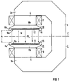
- FIG. 1 shows a basic embodiment of a homogeneous field magnet.
- FIG. 2 shows an enlarged section of a pole piece of this magnet designed according to the invention.
- identical parts are provided with the same reference symbols.
- the homogeneous field magnet shown in the schematic longitudinal section in FIG. 1 is generally designated by 2. It has a one-leg magnetic yoke 3 e.g. made of iron in the form of a "C".
- the two opposite, free leg ends 3a and 3b of the yoke 3 each open into an at least approximately cylindrical core 4 or 5 made of ferromagnetic material. These cores leading towards one another are each enclosed by their own excitation coil 7 or 8.
- the two cores 4 and 5 On the sides facing away from the leg ends 3a and 3b, the two cores 4 and 5 each merge into a widening pole shoe 10 and 11, respectively. This results in a structure of the entire magnet 2 that is at least largely symmetrical with respect to a plane of symmetry E.
- a space or useful volume N is formed between the pole faces 10a and 11a of the two pole shoes 10 and 11, which are spaced apart by a distance A.
- this useful volume there should be a magnetic field with magnetic induction B O which is sufficiently homogeneous for magnetic resonance imaging and which is caused by the two excitation coils 7 and 8.
- Each of the pole pieces 10 and 11 contains a magnetic flux Base part 10b or 11b, which is connected to the yoke 3 via the respective core 4 or 5.
- Each base part 10b or 11b has a free surface which is practically flat except for an edge area and has a bead-like edge piece 10c or 11c in the edge area which reduces the mutual distance A.
- These ring-shaped edge pieces are used for field correction.
- a special pole plate device 12 or 13 designed according to the invention is arranged in each inner, central region of the pole shoes bounded by these edge pieces.
- Each of these pole plate devices 12 and 13 should be spaced apart from the respectively assigned base part 10b or 11b by a narrow, axial correction air gap 14 or 15.
- gradient coils (not shown) for generating pulsed gradient fields required for magnetic resonance imaging are generally located in the immediate vicinity of the surfaces 10a and 11a of the pole plate devices 12 and 13 facing the useful volume N.
- FIG. 1 shows an enlarged section of part of one of the two pole pieces of the magnet 2 according to FIG. 1, for example the pole piece 10.
- FIG. 1 shows an enlarged section of part of one of the two pole pieces of the magnet 2 according to FIG. 1, for example the pole piece 10.
- Corresponding design features should also be provided for the pole piece 11.
- the base part 10b having a largely trapezoidal cut surface has a stepped surface 16 evident.
- This surface is divided into a central surface part 16a of a central, central pole region 17a and an outer surface part 16b of an edge region 17b.
- a step 18 is formed between these two areas, so that there is an edge piece 10c of the base part.
- the edge piece can, for example, have a trapezoidal or rectangular cross-sectional area. It can be formed in one piece with the base part 10b or can be attached to the base part as a separate component.
- the base part can also be profiled in another form.
- the pole plate device 12 In the central, central pole region 17a, the pole plate device 12 is arranged separated from the surface part 16a by a narrow axial correction air gap 14 of width a. A radial gap 20 should remain between the outer edge of the pole plate device and the edge piece 10c. Adjusting devices for fixing and for tilting and / or bending the pole plate device 12 are well known (cf. e.g. the aforementioned DE-OS 37 37 133). They are therefore omitted from the drawing.
- the entire pole plate device 12 (and accordingly also the entire pole plate device 13) generally has a rectangular cross-sectional area, wherein it is designed to be relatively thin compared to its radius R. So their constant thickness D is generally between 0.3 and 3 cm, preferably between 5 and 15 mm. According to the invention, the pole plate device 12 is to be divided into two pole plate elements 12a and 12b be aligned parallel to each other and spaced by a gap 22 of width w.
- the pole plate element 12a facing the base part 10b is to consist of a soft magnetic material, the relative permeability ⁇ r 1 of which is at least a factor 5, preferably at least a factor 10, lower than the relative permeability ⁇ r 2 of the soft magnetic material used for the the pole plate element 12b facing the useful volume N is provided.
- the relative permeability ⁇ r 2 should be at least 10,000, preferably at least 50,000.
- the two pole plate elements 12a and 12b also have different thicknesses d1 and d2, where d1> d2.
- the thickness d1 of the pole plate element 12a is generally between 3 and 25 mm, while a thickness d2 between 1 and 5 mm is generally chosen for the pole plate element 12b.
- the thus thicker pole plate element 12a essentially takes over the radial flux distribution of the basic magnetic field. It should therefore consist of a material with a sufficiently high magnetic saturation induction B s . Pure iron (B s ⁇ 1.8 T) or Fe-Si alloys with Si contents between 2 and 7 atom% (B s > 1.5 T) are therefore preferably suitable for this. These materials have a relative permeability ⁇ r 1, which is generally between 1000 and 5000. In contrast, the magnetic gradient flux generated by the gradient coils is essentially only detected by the thinner pole plate element 12b made of the highly permeable material.
- materials with a particularly low magnetic coercive force H c should be selected.
- Materials that meet these requirements are in particular special Fe-Ni alloys with a Ni content between 40 and 85 atom%. Examples of such alloys are the materials with the trade name "MUMETALL” (with 72 to 83 atom% Ni) and “PERMENORM 5000" (with 45 to 50 atom% Ni) from "Vacuumschmelze GmbH", Hanau, DE (cf. also the book of this company "soft magnetic materials", 4th edition, 1990, pages 278 and 279).
- a sufficient width w of the gap 22 is essential for the homogeneous magnet according to the invention, in order to ensure sufficient magnetic decoupling between the two pole plate elements 12a and 12b. Otherwise, radial magnetic flux would pass from the pole plate element 12a into the highly permeable pole plate element 12b and magnetically saturate it. That is, saturation of the highly permeable material of the pole plate element 12b due to a magnetic field strength H caused by the pole plate element 12a must be prevented, that is, a magnetic short circuit must be avoided.
- the source of the field strength H can be the radial magnetic flux in the pole plate element 12a or the coercive field strength H c of its material.
- B ' ⁇ O * H c * R2 / (8 * w * d2)
- B ' is the magnetic induction caused in the pole plate element 12b.
- B ' should at most about 1/5 to 2/3, preferably 1/3 to 1/2 of the saturation induction B.
- H c is the coercive force of the material of the pole plate element 12a.
- ⁇ O is the universal magnetic field constant.
- the gap 22 between the pole plate elements 12a and 12b can advantageously by a plate made of plastic or a non-magnetic metal such as aluminum or Copper to be filled out.
- a compact, manageable component as a pole plate device 12 is then formed from the stack of plates comprising the elements 12a, 12b and the plate filling the gap 22, for example by gluing or by a large number of thin non-magnetic screws.
Landscapes
- Physics & Mathematics (AREA)
- Electromagnetism (AREA)
- Engineering & Computer Science (AREA)
- Power Engineering (AREA)
- Condensed Matter Physics & Semiconductors (AREA)
- General Physics & Mathematics (AREA)
- Magnetic Resonance Imaging Apparatus (AREA)
Abstract
Description
Die Erfindung bezieht sich auf einen Homogenfeldmagneten mit einem den magnetischen Fluß führenden Joch und zwei gegenüberliegenden Polschuhen, zwischen denen ein Nutzvolumen mit einem Magnetfeld hoher Homogenität ausgebildet ist, wobei jeder Polschuh mit einer Polplatteneinrichtung versehen ist, welche gegenüber einem dem Joch zugewandten Basisteil des jeweiligen Polschuhs über einen schmalen Korrekturluftspalt beabstandet ist und wenigstens zwei zueinander parallele Polplattenelemente aus unterschiedlichen Materialien enthält. Ein entsprechender Homogenfeldmagnet ist z.B. aus der EP 0 488 015 A1 zu entnehmen.The invention relates to a homogeneous field magnet with a yoke guiding the magnetic flux and two opposite pole pieces, between which a useful volume is formed with a magnetic field of high homogeneity, each pole piece being provided with a pole plate device which is opposite a base part of the respective pole piece facing the yoke is spaced apart via a narrow correction air gap and contains at least two mutually parallel pole plate elements made of different materials. A corresponding homogeneous field magnet is e.g. can be seen from EP 0 488 015 A1.
Homogenfeldmagnete sind insbesondere zur Erzeugung magnetischer Grundfelder in Anlagen zur Kernspintomographie (Nuclear-Magnetic-Resonance-Tomography, -Imaging oder -Spectroscopy) erforderlich. Das Magnetfeld derartiger Grundfeldmagnete muß dabei in einem Abbildungs- bzw. Untersuchungsbereich (Nutzvolumen) hinreichend homogen sein und dort eine vorbestimmte magnetische Induktion BO erzeugen. Dabei werden für magnetische Induktionen BO > 0,5 T im allgemeinen supraleitende Spulensysteme vorgesehen. Demgegenüber sind geringere magnetische Induktionen BO < 0,5 T auch mit normalleitenden Spulen oder Permanentmagneten zu erzeugen. Letztere Magnete sind vielfach als sogenannte Polschuhmagnete mit einem Magnetjoch in Form eines "C" oder "H" ausgebildet. Zwischen den Polflächen ihrer gegenüberliegenden Polschuhe liegt dann das Nutzvolumen mit der geforderten Feldhomogenität. Insbesondere für die Anforderungen der Kernspintomographie ist wegen der unvermeidlichen Herstellungstoleranzen die anfänglich erreichbare Feldhomogenität im Nutzvolumen nicht ausreichend. Es muß vielmehr am fertigen Magneten eine Korrekturmöglichkeit bestehen, um so durch eine abwechselnde Folge von Feldmessungen und Feldkorrekturen den Feldfehler sukzessive verringern zu können (sogenannte "Shim-Prozedur").Homogeneous field magnets are particularly necessary for the generation of basic magnetic fields in nuclear magnetic resonance imaging (nuclear magnetic resonance tomography, imaging or spectroscopy) systems. The magnetic field of such basic field magnets must be sufficiently homogeneous in an imaging or examination area (usable volume) and generate a predetermined magnetic induction B O there . Superconducting coil systems are generally provided for magnetic induction B O > 0.5 T. In contrast, lower magnetic induction B O <0.5 T can also be generated with normally conductive coils or permanent magnets. The latter magnets are common designed as a so-called pole shoe magnet with a magnetic yoke in the form of a "C" or "H". The useful volume with the required field homogeneity then lies between the pole faces of their opposite pole shoes. The initially achievable field homogeneity in the usable volume is not sufficient, in particular for the requirements of magnetic resonance imaging, because of the inevitable manufacturing tolerances. Rather, there must be a possibility of correction on the finished magnet in order to be able to successively reduce the field error by an alternating sequence of field measurements and field corrections (so-called "shim procedure").
Aus der genannten EP-A geht ein Polschuhmagnet hervor, welcher mechanische Feldkorrekturmöglichkeiten aufweist. Hierzu sind seine Polschuhe im Bereich ihrer Polflächen aus justierbare Polplatteneinrichtungen gestaltet. Außerdem können die dem Nutzvolumen zugewandten Oberflächen der Polschuhe so profiliert sein, daß insbesondere Randeffekte, welche die Homogenität beeinflussen, kompensiert werden.A pole shoe magnet emerges from the aforementioned EP-A, which has mechanical field correction possibilities. For this purpose, its pole pieces are designed in the area of their pole faces from adjustable pole plate devices. In addition, the surfaces of the pole shoes facing the useful volume can be profiled in such a way that, in particular, edge effects which influence the homogeneity are compensated for.
Um derartige Polplatteneinrichtungen gegenseitig hinreichend exakt ausrichten und Feldfehler korrigieren zu können, ist bei dem bekannten Homogenfeldmagneten jede der Polplatteneinrichtungen nicht unmittelbar an dem einen magnetischen Fluß führenden Magnetjoch befestigt. Vielmehr ist jede Polplatteneinrichtung gegenüber einem dem Joch zugewandten Basisteil des Polschuhes über einen schmalen Korrekturluftspalt beabstandet, wobei sie mittels besonderer Stellvorrichtungen kipp- und/oder biegbar ausgebildet ist. Der Luftspalt wirkt dabei als magnetischer Serienwiderstand feldhomogenisierend, indem er Flußdichteinhomogenitäten in flußführenden Teilen des Polschuhs beim Übertritt in die jeweilige Polplatteneinrichtung ausgleicht.In order to be able to align such pole plate devices with one another with sufficient precision and to be able to correct field errors, in the known homogeneous field magnet each of the pole plate devices is not directly attached to the magnetic yoke carrying a magnetic flux. Rather, each pole plate device is spaced apart from a base part of the pole shoe facing the yoke by a narrow correction air gap, wherein it is designed to be tiltable and / or bendable by means of special adjusting devices is. The air gap acts as a magnetic series resistance to homogenize the field by compensating for flux density inhomogeneities in flux-carrying parts of the pole shoe when it enters the respective pole plate device.
Gemäß einer besonderen Ausführungsform des bekannten Homogenfeldmagneten kann jede seiner Polplatteneinrichtungen auch durch einen stapelartigen Aufbau aus zwei etwa gleichdicken, schichtartigen Polplattenelementen gebildet werden, wobei für diese Elemente unterschiedliche weichmagnetische Materialien gewählt sind. Das erste, dem Korrekturluftspalt zugewandte Polplattenelement läßt sich z.B. aus mindestens einem Elektroblech aus einer Fe-Si-Legierung erstellen, wobei eine hinreichende Flexibilität des Elementes zu gewährleisten ist. Demgegenüber kann das zweite, dem Nutzvolumen zugewandte Polplattenelement beispielsweise aus einem weichmagnetischen Ferrit oder aus einem kunststoffgebundenen Eisenpulver bestehen. Bei einer relativen Permeabilität µr ![]()
von etwa 1000 und einer Flußtragfähigkeit Bmax von etwa 0,4 T bis 0,5 T des Materials dieser zweiten Schicht weist dieses Material vorteilhaft nur eine geringe elektrische Leitfähigkeit auf. Die erste Schicht soll demgegenüber für eine gute Grundfeldhomogenität sorgen. Hierzu besteht sie aus einem Material mit einer relativen Permeabilität µr zwischen 1000 und 5000 bei zugleich hoher Flußtragfähigkeit Bmax von etwa 1,6 T.According to a special embodiment of the known homogeneous field magnet, each of its pole plate devices can also be formed by a stack-like structure made of two layer-like pole plate elements of approximately the same thickness, different soft magnetic materials being selected for these elements. The first pole plate element facing the correction air gap can be produced, for example, from at least one electrical sheet made of an Fe-Si alloy, with sufficient flexibility of the element being ensured. In contrast, the second pole plate element facing the usable volume can consist, for example, of a soft magnetic ferrite or of a plastic-bonded iron powder. With a relative permeability µ r ![]()
of about 1000 and a flow capacity B max of about 0.4 T to 0.5 T of the material of this second layer, this material advantageously has only a low electrical conductivity. The first layer, on the other hand, should ensure good basic field homogeneity. For this purpose it consists of a material with a relative permeability µ r between 1000 and 5000 with a high flow capacity B max of about 1.6 T.
Derartige Platteneinrichtungen tragen auch einen von gepulsten Gradientenspulen erzeugten magnetischen Fluß. Es zeigt sich dann aber, daß eine magnetische Hysterese des Plattenmaterials zu Restfeldern nach einem Gradientenpuls und zu einem nicht-linearen Strom-Feld-Zusammenhang führt. Hierdurch kann die Bildgüte bekannter bildgebender Verfahren wie z.B. des als "Turbo-Spin-Echo" bezeichneten Verfahrens beeinträchtigt werden. Das Auftreten von Hystereseerscheinungen ist auch eine Ursache von Fehlern im magnetischen Grundfeld. Je nach dem, ob ein Betriebsstrom vorhandener Erregerspulen von niedrigeren oder höheren Werten aus erreicht wird, ergibt sich nämlich ein anderes Spektrum der Feldfehler. Diese Tatsache erschwert eine Shim-Prozedur zur Einstellung einer optimalen Grundfeldhomogenität.Such plate devices also carry a magnetic flux generated by pulsed gradient coils. It it then turns out, however, that magnetic hysteresis of the plate material leads to residual fields after a gradient pulse and to a non-linear current-field relationship. As a result, the image quality of known imaging methods, such as, for example, the method referred to as "turbo spin echo" can be impaired. The occurrence of hysteresis is also a cause of errors in the basic magnetic field. Depending on whether an operating current of existing excitation coils is reached from lower or higher values, there is a different spectrum of field errors. This fact complicates a shim procedure for setting an optimal basic field homogeneity.
Aufgabe der vorliegenden Erfindung ist es, bei einem Homogenfeldmagneten mit den eingangs genannten Merkmalen diese auf eine Hysterese zurückzuführenden Fehler auf ein unschädliches Maß zu verringern.It is an object of the present invention to reduce to a harmless level those errors which can be attributed to hysteresis in a homogeneous field magnet having the features mentioned at the beginning.
Diese Aufgabe wird erfindungsgemäß dadurch gelöst, daß die Polplattenelemente gegenseitig durch einen Spalt vorbestimmter Weite beabstandet sind und daß an jedem Polschuh das dem Basisteil zugewandte Polplattenelement aus einem Material besteht, dessen relative Permeabilität mindestens um einen Faktor 5 geringer ist als die relative Permeabilität des Materials des dem Nutzvolumen zugewandten Polplattenelements, die mindestens 10000 beträgt.This object is achieved in that the pole plate elements are mutually spaced by a gap of predetermined width and that on each pole piece the pole plate element facing the base part consists of a material whose relative permeability is at least a factor 5 less than the relative permeability of the material of the the useful volume facing pole plate element, which is at least 10,000.
Die mit dieser Ausgestaltung des Homogenfeldmagneten verbundenen Vorteile sind insbesondere darin zu sehen, daß das hochpermeable Material des dem Nutzvolumen zugewandten Polplattenelementes nur eine geringe Hystereses zeigt. Dieses Polplattenelement trägt im wesentlichen den magnetischen Gradientenfluß, der folglich nur in entsprechend geringem Maße von Restfehlern nach einem Gradientenpuls beeinflußt wird. Demgegenüber übernimmt die Radialflußverteilung des magnetischen Grundfeldes im wesentlichen das dem Basisteil des Polschuhs zugewandte Polplattenelement. In diesem Element spielen Hystereseeffekte nur eine nebensächliche Rolle. Zwischen beiden Polplattenelementen liegt der Spalt als eine magnetische Entkopplungseinrichtung. Dieser Spalt verhindert, daß der radiale Fluß in dem dem Basisteil zugewandten Polplattenelement in das hochpermeable Material des parallelliegenden Plattenelementes übertreten und dieses magnetisch sättigen kann. Deshalb können für diese Polplattenelemente vorteilhaft bekannte hochpermeable Materialien verwendet werden, die eine vergleichsweise geringere magnetische Sättigungsinduktion Bs als die Materialien der dem Basisteil zugewandten Polplattenelemente haben.The advantages associated with this configuration of the homogeneous field magnet can be seen, in particular, in the fact that the highly permeable material faces the usable volume The pole plate element shows only a slight hysteresis. This pole plate element essentially carries the magnetic gradient flux, which consequently is only influenced to a correspondingly small extent by residual errors after a gradient pulse. In contrast, the radial flux distribution of the basic magnetic field essentially takes over the pole plate element facing the base part of the pole piece. Hysteresis effects only play a minor role in this element. The gap between the two pole plate elements is a magnetic decoupling device. This gap prevents the radial flow in the pole plate element facing the base part from passing into the highly permeable material of the parallel plate element and being able to magnetically saturate it. Known highly permeable materials which have a comparatively lower magnetic saturation induction B s than the materials of the pole plate elements facing the base part can therefore advantageously be used for these pole plate elements.
Weitere vorteilhafte Ausgestaltungen des erfindungsgemäßen Homogenfeldmagneten gehen aus den abhängigen Ansprüchen hervor.Further advantageous embodiments of the homogeneous field magnet according to the invention emerge from the dependent claims.
Zur weiteren Erläuterung der Erfindung wird nachfolgend auf die Zeichnung Bezug genommen, in deren Figur 1 eine prinzipielle Ausführungsform eines Homogenfeldmagneten angedeutet ist. Figur 2 gibt einen vergrößerten Ausschnitt aus einem erfindungsgemäß gestalteten Polschuh dieses Magneten wieder. In den Figuren sind übereinstimmende Teile mit denselben Bezugszeichen versehen.To further explain the invention, reference is made below to the drawing, in FIG. 1 of which a basic embodiment of a homogeneous field magnet is indicated. FIG. 2 shows an enlarged section of a pole piece of this magnet designed according to the invention. In the figures, identical parts are provided with the same reference symbols.
Bei einem erfindungsgemäßen Homogenfeldmagneten wird von bekannten Ausführungsformen ausgegangen, wie sie sich insbesondere für die Kernspintomographie vorsehen lassen (vgl. z.B. die genannte EP-A oder die DE-OS 37 37 133). Nicht näher erläuterte Teile des Magneten entsprechen deshalb denen dieser bekannten Ausführungsformen.In the case of a homogeneous field magnet according to the invention, known embodiments are assumed, such as can be provided in particular for magnetic resonance imaging (cf. e.g. the aforementioned EP-A or DE-OS 37 37 133). Parts of the magnet which are not explained in greater detail therefore correspond to those of these known embodiments.
Der aus dem schematischen Längsschnitt der Figur 1 ersichtliche Homogenfeldmagnet ist allgemein mit 2 bezeichnet. Er weist ein einschenkliges magnetisches Joch 3 z.B. aus Eisen in Form eines "C" auf. Die beiden gegenüberliegenden, freien Schenkelenden 3a bz. 3b des Joches 3 münden jeweils in einen wenigstens annähernd zylinderförmigen Kern 4 bzw. 5 aus ferromagnetischem Material. Diese aufeinander zuführenden Kerne sind dabei jeweils von einer eigenen Erregerspule 7 bzw. 8 umschlossen. An den den Schenkelenden 3a bzw. 3b abgewandten Seiten gehen die beiden Kerne 4 und 5 jeweils in einen sich verbreiternden Polschuh 10 bzw. 11 über. Es ergibt sich so ein zu einer Symmetrieebene E zumindest weitgehend symmetrischer Aufbau des gesamten Magneten 2.The homogeneous field magnet shown in the schematic longitudinal section in FIG. 1 is generally designated by 2. It has a one-leg magnetic yoke 3 e.g. made of iron in the form of a "C". The two opposite,
Zwischen den um einen Abstand A beabstandeten Polflächen 10a und 11a der beiden Polschuhe 10 bzw. 11 ist ein Zwischenraum oder Nutzvolumen N ausgebildet. In diesem Nutzvolumen soll ein zur Kernspintomographie hinreichend homogenes Magnetfeld mit einer magnetischen Induktion BO herrschen, das von den beiden Erregerspulen 7 und 8 hervorgerufen wird.A space or useful volume N is formed between the
Jeder der Polschuhe 10 und 11 enthält einen magnetflußführenden Basisteil 10b bzw. 11b, der über den jeweiligen Kern 4 oder 5 mit dem Joch 3 verbunden ist. Jeder Basisteil 10b bzw. 11b hat eine freie, bis auf einen Randbereich praktisch ebene Fläche und weist in dem Randbereich ein den gegenseitigen Abstand A verringerndes wulstartiges Randstück 10c bzw. 11c auf. Diese ringförmigen Randstücke dienen zur Feldkorrektur. In jedem von diesen Randstücken umgrenzten inneren, zentralen Bereich der Polschuhe ist eine besondere, erfindungsgemäß gestaltete Polplatteneinrichtung 12 bzw. 13 angeordnet. Jede dieser Polplatteneinrichtungen 12 und 13 soll dabei von dem jeweils zugeordneten Basisteil 10b bzw. 11b durch einen schmalen, axialen Korrekturluftspalt 14 bzw. 15 beabstandet sein. Ferner befinden sich in der Figur nicht dargestellten Gradientenspulen zur Erzeugung von zur Kernspintomographie erforderlichen gepulsten Gradientenfeldern im allgemeinen in unmittelbarer Nähe der dem Nutzvolumen N zugewandten Oberflächen 10a und 11a der Polplatteneinrichtungen 12 und 13.Each of the
Die erfindungsgemäße Ausgestaltung der Polplatteneinrichtungen geht aus dem in Figur 2 gezeigten schematischen Längsschnitt hervor. In dieser Figur ist ein vergrößerter Ausschnitt aus einem Teil eines der beiden Polschuhe des Magneten 2 nach Figur 1, beispielsweise des Polschuhs 10 dargestellt. Entsprechende Gestaltungsmerkmale sollen auch für den Polschuh 11 vorgesehen werden.The configuration of the pole plate devices according to the invention can be seen from the schematic longitudinal section shown in FIG. This figure shows an enlarged section of part of one of the two pole pieces of the
Aus dem in Figur 2 gezeigten Schnitt durch einen zu einer Mittellinie M rotationssymmetrischen Teil des Polschuhs 10 ist der eine weitgehend trapezförmige Schnittfläche aufweisende Basisteil 10b mit einer gestuften Oberfläche 16 ersichtlich. Diese Oberfläche ist in einen mittleren Oberflächenteil 16a eines mittleren, zentralen Polbereichs 17a und in einen äußeren Oberflächenteil 16b eines Randbereichs 17b unterteilt. Zwischen diesen beiden Bereichen ist eine Stufe 18 ausgebildet, so daß sich ein Randstück 10c des Basisteils ergibt. Das Randstück kann beispielsweise eine trapezförmige oder auch rechteckige Querschnittsfläche haben. Es kann einstückig mit dem Basisteil 10b ausgebildet oder als ein eigenes Bauteil an den Basisteil angefügt sein. Der Basisteil kann aber auch in anderer Form profiliert sein.From the section shown in FIG. 2 through a part of the
In dem mittleren, zentralen Polbereich 17a ist von dem Oberflächenteil 16a durch einen schmalen axialen Korrekturluftspalt 14 der Weite a getrennt die Polplatteneinrichtung 12 angeordnet. Dabei soll zwischen dem Außenrand der Polplatteneinrichtung und dem Randstück 10c ein radialer Spalt 20 verbleiben. Stellvorrichtungen zum Fixieren sowie zum Kippen und/oder Biegen der Polplatteneinrichtung 12 sind hinlänglich bekannt (vgl. z.B. die genannte DE-OS 37 37 133). Sie sind deshalb in der Zeichnung weggelassen.In the central,
Die gesamte Polplatteneinrichtung 12 (und entsprechend auch die gesamte Polplatteneinrichtung 13) weist im allgemeinen eine rechteckige Querschnittsfläche auf, wobei sie im Vergleich zu ihrem Radius R verhältnismäßig dünn ausgebildet ist. So liegt ihre konstante Dicke D im allgemeinen zwischen 0,3 und 3 cm, vorzugsweise zwischen 5 und 15 mm. Die Polplatteneinrichtung 12 soll erfindungsgemäß in zwei Polplattenelemente 12a und 12b unterteilt sein, die parallel zueinander ausgerichtet und durch einen Spalt 22 der Weite w beabstandet sind. Dabei soll das dem Basisteil 10b zugewandte Polplattenelement 12a aus einem weichmagnetischen Material bestehen, dessen relative Permeabilität µr1 mindestens um einen Faktor 5, vorzugsweise mindestens um einen Faktor 10, geringer ist als die relative Permeabilität µr2 des weichmagnetischen Materials, welches für das dem Nutzvolumen N zugewandte Polplattenelement 12b vorgesehen wird. Die relative Permeabilität µr2 soll dabei mindestens 10000, vorzugsweise mindestens 50000 betragen. Wie ferner aus Figur 2 zu entnehmen ist, weisen die beiden Polplattenelemente 12a und 12b auch unterschiedliche Dicken d1 bzw. d2 auf, wobei d1 > d2 ist. Die Dicke d1 des Polplattenelementes 12a liegt dabei im allgemeinen zwischen 3 und 25 mm, während für das Polplattenelement 12b im allgemeinen eine Dicke d2 zwischen 1 und 5 mm gewählt wird. Das somit dickere Polplattenelement 12a übernimmt im wesentlichen die Radialflußverteilung des magnetischen Grundfeldes. Es sollte deshalb aus einem Material mit einer hinreichend hohen magnetischen Sättigungsinduktion Bs bestehen. Deshalb sind hierfür vorzugsweise Reineisen (Bs ≈ 1,8 T) oder Fe-Si-Legierungen mit Si-Gehalten zwischen 2 und 7 Atom-% (Bs > 1,5 T) geeignet. Diese Materialien weisen eine relative Permeabilität µr1 auf, die im allgemeinen zwischen 1000 und 5000 liegt. Demgegenüber wird der von den Gradientenspulen erzeugte magnetische Gradientenfluß im wesentlichen nur von dem dünneren Polplattenelement 12b aus dem hochpermeablen Material erfaßt. Zur Unterdrückung von Hystereseseffekten sind hierfür Materialien mit besonders geringer magnetischer Koerzitivfeldstärke Hc, insbesondere mit Hc ≦ 0,05 A/cm auszuwählen. Materialien, die diese Anforderungen erfüllen, sind insbesondere spezielle Fe-Ni-Legierungen mit einem Ni-Gehalt zwischen 40 und 85 Atom-%. Beispiele entsprechender Legierungen sind die Materialien mit dem Handelsnamen "MUMETALL" (mit 72 bis 83 Atom-% Ni) und "PERMENORM 5000" (mit 45 bis 50 Atom-% Ni) der Firma "Vacuumschmelze GmbH", Hanau, DE (vgl. auch das Buch dieser Firma "Weichmagnetische Werkstoffe", 4. Auflage, 1990, Seiten 278 und 279).The entire pole plate device 12 (and accordingly also the entire pole plate device 13) generally has a rectangular cross-sectional area, wherein it is designed to be relatively thin compared to its radius R. So their constant thickness D is generally between 0.3 and 3 cm, preferably between 5 and 15 mm. According to the invention, the
Wesentlich für den erfindungsgemäßen Homogenmagneten ist eine ausreichende Weite w des Spaltes 22, um eine hinreichende magnetische Entkopplung zwischen den beiden Polplattenelementen 12a und 12b zu gewährleisten. Andernfalls würde nämlich radialer magnetischer Fluß aus dem Polplattenelement 12a in das hochpermeable Polplattenelement 12b übertreten und dieses magnetisch sättigen. D.h., es muß eine Sättigung des hochpermeablen Materials des Polplattenelements 12b aufgrund einer von dem Polplattenelement 12a verursachten magnetischen Feldstärke H verhindert werden, also ein magnetischer Kurzschluß vermieden werden. Die Quelle der Feldstärke H kann dabei der radiale magnetische Fluß in dem Polplattenelement 12a oder die Koerzitivfeldstärke Hc dessen Materials sein. Durch Aufsummieren des vom Polplattenelement 12a in das Polplattenelement 12b übertretenden magnetischen Flusses unter Annahme der Bedingung ![]()
![]()
Hierbei ist B' die in dem Polplattenelement 12b hervorgerufene magnetische Induktion. B' sollte dabei höchstens etwa 1/5 bis 2/3, vorzugsweise 1/3 bis 1/2 der Sättigungsinduktion B![]()
![]()
![]()
Here, B 'is the magnetic induction caused in the pole plate element 12b. B 'should at most about 1/5 to 2/3, preferably 1/3 to 1/2 of the saturation induction B. ![]()
Aus der vorstehenden Abschätzung ergibt sich dann unter Zugrundelegung der erfindungsgemäß vorgesehenen Materialien und von üblichen Abmessungen der Polplattenelemente 12a und 12b für die Spaltweite w: 1 mm ≦ w ≦ 6 mm.On the basis of the materials provided according to the invention and the usual dimensions of the pole plate elements 12a and 12b for the gap width w: 1 mm ≦ w ≦ 6 mm, the above estimate then results.
- R
- der Polplattenelemente 12a und 12b: 0,4 m
- Hc
- von FeSi(3 Atom-%)-Legierung des Polplattenelements 12a: 0,5 A/cm
- d2
- des Polplattenelements 12b:2 mm
- B'
- von FeNi(72-83 Atom-%, Zusätze von Cu, Mo. u.a.)-Legierung (beispielsweise "MUMETALL") des Polplattenelements 12b: 0,2 T (≈ (1/4) * B

Dann ergibt sich für Spaltweite w ≈ 4 mm.
Das Polplattenelement 12b kann dabei einen magnetischen Fluß von 4 * 10⁻⁴ Vs/m tragen, der durch einen magnetischen
- R
- the pole plate elements 12a and 12b: 0.4 m
- H c
- of FeSi (3 atom%) alloy of the pole plate element 12a: 0.5 A / cm
- d2
- of the pole plate element 12b: 2 mm
- B '
- of FeNi (72-83 atom%, additions of Cu, Mo. etc.) alloy (for example "MUMETALL") of the pole plate element 12b: 0.2 T (≈ (1/4) * B
Then the gap width is w ≈ 4 mm.
The pole plate element 12b can carry a magnetic flux of 4 * 10⁻⁴ Vs / m, which is generated by a magnetic field gradient of 10 mT / m.
Der Spalt 22 zwischen den Polplattenelementen 12a und 12b kann vorteilhaft durch eine Platte aus Kunststoff oder aus einem nicht-magnetischen Metall wie z.B. Aluminium oder Kupfer ausgefüllt werden. Aus dem Plattenstapel aus den Elementen 12a, 12b und der den Spalt 22 ausfüllenden Platte wird dann z.B. durch Verkleben oder durch eine Vielzahl dünner unmagnetischer Schrauben ein kompaktes handhabbares Bauteil als Polplatteneinrichtung 12 gebildet.The
Abweichend von der aus den Figuren ersichtlichen Ausführungsform eines erfindungsgemäßen Homogenfeldmagneten kann dieser auch eine andere Gestalt, z.B. in Form eines "H", haben. Ferner können seine Polplattenelemente selbstverständlich auch lamelliert sein. Darüber hinaus braucht die Weite a der Korrekturluftspalte 14 und 15 in radialer Richtung gesehen nicht konstant zu sein (vgl. die genannte EP-A).Deviating from the embodiment of a homogeneous field magnet according to the invention shown in the figures, this can also have a different shape, e.g. in the form of an "H". Furthermore, its pole plate elements can of course also be laminated. In addition, the width a of the
Claims (10)
Applications Claiming Priority (2)
| Application Number | Priority Date | Filing Date | Title |
|---|---|---|---|
| DE4308208 | 1993-03-15 | ||
| DE4308208 | 1993-03-15 |
Publications (2)
| Publication Number | Publication Date |
|---|---|
| EP0616230A1 true EP0616230A1 (en) | 1994-09-21 |
| EP0616230B1 EP0616230B1 (en) | 1998-08-05 |
Family
ID=6482852
Family Applications (1)
| Application Number | Title | Priority Date | Filing Date |
|---|---|---|---|
| EP94103114A Expired - Lifetime EP0616230B1 (en) | 1993-03-15 | 1994-03-02 | Homogeneous field magnet with pole plate spaced by correction air-gap for each pole shoe |
Country Status (4)
| Country | Link |
|---|---|
| US (1) | US5363078A (en) |
| EP (1) | EP0616230B1 (en) |
| JP (1) | JP3514806B2 (en) |
| DE (1) | DE59406586D1 (en) |
Cited By (2)
| Publication number | Priority date | Publication date | Assignee | Title |
|---|---|---|---|---|
| DE19813211C2 (en) * | 1998-03-25 | 2000-05-18 | Siemens Ag | Superconducting device with conductors made of high-T¶c¶ superconducting material |
| US7260941B2 (en) | 2002-05-15 | 2007-08-28 | Siemens Aktiengesellschaft | Superconductor device having superconductive magnet and refrigeration unit |
Families Citing this family (12)
| Publication number | Priority date | Publication date | Assignee | Title |
|---|---|---|---|---|
| FI933834A (en) * | 1993-09-01 | 1995-03-02 | Picker Nordstar Oy | Polsko for a magnetographic imaging device |
| JP3143371B2 (en) * | 1995-09-19 | 2001-03-07 | 信越化学工業株式会社 | Magnetic resonance imaging equipment |
| JP3014319B2 (en) * | 1996-04-12 | 2000-02-28 | 信越化学工業株式会社 | Magnet facing permanent magnet circuit |
| JP3283242B2 (en) * | 1999-06-21 | 2002-05-20 | ジーイー横河メディカルシステム株式会社 | Gradient coil manufacturing method, gradient coil and MRI apparatus |
| JP3705995B2 (en) * | 2000-04-19 | 2005-10-12 | ジーイー・メディカル・システムズ・グローバル・テクノロジー・カンパニー・エルエルシー | Gradient coil manufacturing method, gradient coil, and magnetic resonance imaging apparatus |
| JP4051301B2 (en) * | 2003-02-12 | 2008-02-20 | ジーイー・メディカル・システムズ・グローバル・テクノロジー・カンパニー・エルエルシー | Circular pole piece and MRI equipment |
| CN100434928C (en) * | 2003-05-23 | 2008-11-19 | 西门子(中国)有限公司 | Magnetic field generating system used for magnetic resonance equipment |
| JP5234990B2 (en) | 2009-05-13 | 2013-07-10 | 住友重機械工業株式会社 | Bearing structure |
| JP6281677B2 (en) * | 2013-03-08 | 2018-02-21 | 国立大学法人名古屋大学 | Magnetic measuring device |
| US9933392B2 (en) * | 2015-09-30 | 2018-04-03 | The Boeing Company | Apparatus, system, and method for non-destructive ultrasonic inspection |
| US10991497B2 (en) * | 2016-02-03 | 2021-04-27 | Adaptas Solutions Pty Ltd | Apparatus and methods for controlling a charged particle in a magnetic field |
| WO2020117662A1 (en) * | 2018-12-06 | 2020-06-11 | Board Of Supervisors Of Louisiana State University And Agricultural And Mechanical College | Method and system for applying pulsed electric fields with high uniformity using magnetic cores |
Citations (7)
| Publication number | Priority date | Publication date | Assignee | Title |
|---|---|---|---|---|
| EP0170318A1 (en) * | 1984-07-17 | 1986-02-05 | Koninklijke Philips Electronics N.V. | Nuclear magnetic resonance apparatus with a permanent magnet |
| JPS61203605A (en) * | 1985-03-07 | 1986-09-09 | Fuji Electric Co Ltd | Magnet having highly uniform magnetic field |
| US4675609A (en) * | 1985-09-18 | 1987-06-23 | Fonar Corporation | Nuclear magnetic resonance apparatus including permanent magnet configuration |
| EP0284439A1 (en) * | 1987-03-27 | 1988-09-28 | Sumitomo Special Metals Co. Ltd. | Magnetic field generating device |
| DE3737133A1 (en) * | 1987-11-02 | 1989-05-11 | Siemens Ag | Homogeneous field magnet with profiled pole plates |
| EP0488015A1 (en) * | 1990-11-30 | 1992-06-03 | Siemens Aktiengesellschaft | Magnet system for a homogeneous field with at least one mechanically adustable polar piece |
| US5278534A (en) * | 1992-09-01 | 1994-01-11 | New York University | Magnetic structure having a mirror |
Family Cites Families (8)
| Publication number | Priority date | Publication date | Assignee | Title |
|---|---|---|---|---|
| DE1234874B (en) * | 1955-07-22 | 1967-02-23 | Perkin Elmer Corp | Device for generating a homogeneous magnetic field |
| US2917682A (en) * | 1956-07-09 | 1959-12-15 | Schlumberger Well Surv Corp | Magnet |
| GB1084542A (en) * | 1963-04-01 | 1967-09-27 | Perkin Elmer Ltd | Magnets with high-homogeneity working gap |
| US3223897A (en) * | 1963-09-23 | 1965-12-14 | Varian Associates | Apparatus for adjusting the configuration of a magnetic field |
| GB1360606A (en) * | 1971-08-05 | 1974-07-17 | Parker L K | Magnetic systems |
| US4672346A (en) * | 1984-04-11 | 1987-06-09 | Sumotomo Special Metal Co., Ltd. | Magnetic field generating device for NMR-CT |
| JPS63199403A (en) * | 1987-02-14 | 1988-08-17 | Hitachi Metals Ltd | Magnetic field generator |
| JPH03273602A (en) * | 1990-03-23 | 1991-12-04 | Seiko Epson Corp | Magnetic field generator |
-
1994
- 1994-03-02 EP EP94103114A patent/EP0616230B1/en not_active Expired - Lifetime
- 1994-03-02 DE DE59406586T patent/DE59406586D1/en not_active Expired - Lifetime
- 1994-03-09 US US08/209,031 patent/US5363078A/en not_active Expired - Lifetime
- 1994-03-10 JP JP06655494A patent/JP3514806B2/en not_active Expired - Lifetime
Patent Citations (7)
| Publication number | Priority date | Publication date | Assignee | Title |
|---|---|---|---|---|
| EP0170318A1 (en) * | 1984-07-17 | 1986-02-05 | Koninklijke Philips Electronics N.V. | Nuclear magnetic resonance apparatus with a permanent magnet |
| JPS61203605A (en) * | 1985-03-07 | 1986-09-09 | Fuji Electric Co Ltd | Magnet having highly uniform magnetic field |
| US4675609A (en) * | 1985-09-18 | 1987-06-23 | Fonar Corporation | Nuclear magnetic resonance apparatus including permanent magnet configuration |
| EP0284439A1 (en) * | 1987-03-27 | 1988-09-28 | Sumitomo Special Metals Co. Ltd. | Magnetic field generating device |
| DE3737133A1 (en) * | 1987-11-02 | 1989-05-11 | Siemens Ag | Homogeneous field magnet with profiled pole plates |
| EP0488015A1 (en) * | 1990-11-30 | 1992-06-03 | Siemens Aktiengesellschaft | Magnet system for a homogeneous field with at least one mechanically adustable polar piece |
| US5278534A (en) * | 1992-09-01 | 1994-01-11 | New York University | Magnetic structure having a mirror |
Non-Patent Citations (2)
| Title |
|---|
| M.G. ABELE ET AL.: "FIELD COMPUTATION IN PERMANENT MAGNETS", IEEE TRANSACTIONS ON MAGNETICS, vol. 28, no. 1, 1 January 1992 (1992-01-01), NEW YORK US, pages 931 - 934, XP000258114, DOI: doi:10.1109/20.120031 * |
| PATENT ABSTRACTS OF JAPAN vol. 11, no. 36 (E - 477)<2483> 3 February 1987 (1987-02-03) * |
Cited By (2)
| Publication number | Priority date | Publication date | Assignee | Title |
|---|---|---|---|---|
| DE19813211C2 (en) * | 1998-03-25 | 2000-05-18 | Siemens Ag | Superconducting device with conductors made of high-T¶c¶ superconducting material |
| US7260941B2 (en) | 2002-05-15 | 2007-08-28 | Siemens Aktiengesellschaft | Superconductor device having superconductive magnet and refrigeration unit |
Also Published As
| Publication number | Publication date |
|---|---|
| JP3514806B2 (en) | 2004-03-31 |
| US5363078A (en) | 1994-11-08 |
| EP0616230B1 (en) | 1998-08-05 |
| DE59406586D1 (en) | 1998-09-10 |
| JPH06302424A (en) | 1994-10-28 |
Similar Documents
| Publication | Publication Date | Title |
|---|---|---|
| DE69129687T2 (en) | Device for generating a magnetic field for imaging by means of magnetic resonance | |
| DE69325255T2 (en) | Magnetic resonance imaging enhancements | |
| DE69613061T2 (en) | Magnetic circuit arrangement with opposing permanent magnets | |
| DE1946059C3 (en) | Coil arrangement for field homogenization | |
| EP0616230B1 (en) | Homogeneous field magnet with pole plate spaced by correction air-gap for each pole shoe | |
| EP1079236B1 (en) | Actively shielded superconducting magnet assembly with Z2-shim | |
| DE3616078C2 (en) | ||
| EP0525246A1 (en) | Magnet arrangement with a magnetic stray field generating yoke body | |
| DE69301312T2 (en) | Process for the production of multipole magnets | |
| DE69409915T2 (en) | Electropneumatic converter | |
| DE69936494T2 (en) | Magnetic resonance system with shim rings | |
| EP0488015B1 (en) | Magnet system for a homogeneous field with at least one mechanically adustable polar piece | |
| DE2849355A1 (en) | MAGNETIC COIL ARRANGEMENT FOR GENERATING A HOMOGENEOUS MAGNETIC FIELD FOR MAGNETIC RESONANCE ARRANGEMENTS | |
| DE102005028572A1 (en) | Fold magnetic core for hall sensor arrangement, has air gap bridged by yoke bodies overlapping with side pieces, where specific distance exhibits between bodies and pieces, and space provided between fold positions | |
| DE68928610T2 (en) | Passive compensation body for the correction of (3,2) and (3, -2) harmonic elements in magnetic resonance magnets | |
| EP1564562B1 (en) | Hybrid magnet assembly | |
| DE2136237C3 (en) | Nuclear magnetic resonance magnetometer | |
| DE19821739C1 (en) | Mobile magneto-resonance device for NMR or MRI | |
| DE69700319T2 (en) | Magnet arrangement for imaging magnetic resonance with opposing permanent magnets | |
| DE3814260A1 (en) | DEVICE FOR GENERATING MAGNETIC FIELDS FOR A MAGNETIC RESONANCE IMAGING DEVICE | |
| DE102009045373A1 (en) | A compact superconducting magnet arrangement with active shielding, wherein the shielding coil attenuates the field maximum of the main field coil | |
| EP0181383A1 (en) | Spin resonance tomograph. | |
| DE69131940T2 (en) | Apparatus for generating magnetic fields for imaging by means of magnetic resonance | |
| EP0177869B1 (en) | Magnet arrangement with a screen device for a nuclear spin tomography installation | |
| EP0505595A1 (en) | Stepping motor for timepieces |
Legal Events
| Date | Code | Title | Description |
|---|---|---|---|
| PUAI | Public reference made under article 153(3) epc to a published international application that has entered the european phase |
Free format text: ORIGINAL CODE: 0009012 |
|
| AK | Designated contracting states |
Kind code of ref document: A1 Designated state(s): DE FR GB IT |
|
| 17P | Request for examination filed |
Effective date: 19950307 |
|
| GRAG | Despatch of communication of intention to grant |
Free format text: ORIGINAL CODE: EPIDOS AGRA |
|
| 17Q | First examination report despatched |
Effective date: 19971030 |
|
| GRAG | Despatch of communication of intention to grant |
Free format text: ORIGINAL CODE: EPIDOS AGRA |
|
| GRAH | Despatch of communication of intention to grant a patent |
Free format text: ORIGINAL CODE: EPIDOS IGRA |
|
| GRAH | Despatch of communication of intention to grant a patent |
Free format text: ORIGINAL CODE: EPIDOS IGRA |
|
| GRAA | (expected) grant |
Free format text: ORIGINAL CODE: 0009210 |
|
| AK | Designated contracting states |
Kind code of ref document: B1 Designated state(s): DE FR GB IT |
|
| REF | Corresponds to: |
Ref document number: 59406586 Country of ref document: DE Date of ref document: 19980910 |
|
| GBT | Gb: translation of ep patent filed (gb section 77(6)(a)/1977) |
Effective date: 19981012 |
|
| ET | Fr: translation filed | ||
| PLBE | No opposition filed within time limit |
Free format text: ORIGINAL CODE: 0009261 |
|
| STAA | Information on the status of an ep patent application or granted ep patent |
Free format text: STATUS: NO OPPOSITION FILED WITHIN TIME LIMIT |
|
| 26N | No opposition filed | ||
| PGFP | Annual fee paid to national office [announced via postgrant information from national office to epo] |
Ref country code: FR Payment date: 20010327 Year of fee payment: 8 |
|
| REG | Reference to a national code |
Ref country code: GB Ref legal event code: IF02 |
|
| PG25 | Lapsed in a contracting state [announced via postgrant information from national office to epo] |
Ref country code: FR Free format text: LAPSE BECAUSE OF NON-PAYMENT OF DUE FEES Effective date: 20021129 |
|
| REG | Reference to a national code |
Ref country code: FR Ref legal event code: ST |
|
| PG25 | Lapsed in a contracting state [announced via postgrant information from national office to epo] |
Ref country code: IT Free format text: LAPSE BECAUSE OF NON-PAYMENT OF DUE FEES;WARNING: LAPSES OF ITALIAN PATENTS WITH EFFECTIVE DATE BEFORE 2007 MAY HAVE OCCURRED AT ANY TIME BEFORE 2007. THE CORRECT EFFECTIVE DATE MAY BE DIFFERENT FROM THE ONE RECORDED. Effective date: 20050302 |
|
| PGRI | Patent reinstated in contracting state [announced from national office to epo] |
Ref country code: IT Effective date: 20080301 |
|
| PG25 | Lapsed in a contracting state [announced via postgrant information from national office to epo] |
Ref country code: DE Free format text: LAPSE BECAUSE OF NON-PAYMENT OF DUE FEES Effective date: 20111001 |
|
| PGFP | Annual fee paid to national office [announced via postgrant information from national office to epo] |
Ref country code: IT Payment date: 20120328 Year of fee payment: 19 |
|
| PGFP | Annual fee paid to national office [announced via postgrant information from national office to epo] |
Ref country code: GB Payment date: 20130311 Year of fee payment: 20 |
|
| PGFP | Annual fee paid to national office [announced via postgrant information from national office to epo] |
Ref country code: DE Payment date: 20130521 Year of fee payment: 20 |
|
| REG | Reference to a national code |
Ref country code: DE Ref legal event code: R071 Ref document number: 59406586 Country of ref document: DE |
|
| REG | Reference to a national code |
Ref country code: GB Ref legal event code: PE20 Expiry date: 20140301 |
|
| PG25 | Lapsed in a contracting state [announced via postgrant information from national office to epo] |
Ref country code: DE Free format text: LAPSE BECAUSE OF EXPIRATION OF PROTECTION Effective date: 20140304 Ref country code: GB Free format text: LAPSE BECAUSE OF EXPIRATION OF PROTECTION Effective date: 20140301 |