EP0616002A1 - Process for producing polycarbonate powder - Google Patents
Process for producing polycarbonate powder Download PDFInfo
- Publication number
- EP0616002A1 EP0616002A1 EP92920000A EP92920000A EP0616002A1 EP 0616002 A1 EP0616002 A1 EP 0616002A1 EP 92920000 A EP92920000 A EP 92920000A EP 92920000 A EP92920000 A EP 92920000A EP 0616002 A1 EP0616002 A1 EP 0616002A1
- Authority
- EP
- European Patent Office
- Prior art keywords
- polycarbonate
- mixing nozzle
- organic solvent
- steam
- powder
- Prior art date
- Legal status (The legal status is an assumption and is not a legal conclusion. Google has not performed a legal analysis and makes no representation as to the accuracy of the status listed.)
- Granted
Links
- 0 CC(C*)C(CC1)C1(CC*)C(*)C1C(C*)C(*)CC1C Chemical compound CC(C*)C(CC1)C1(CC*)C(*)C1C(C*)C(*)CC1C 0.000 description 4
Images

Classifications
-
- C—CHEMISTRY; METALLURGY
- C08—ORGANIC MACROMOLECULAR COMPOUNDS; THEIR PREPARATION OR CHEMICAL WORKING-UP; COMPOSITIONS BASED THEREON
- C08J—WORKING-UP; GENERAL PROCESSES OF COMPOUNDING; AFTER-TREATMENT NOT COVERED BY SUBCLASSES C08B, C08C, C08F, C08G or C08H
- C08J3/00—Processes of treating or compounding macromolecular substances
- C08J3/12—Powdering or granulating
- C08J3/14—Powdering or granulating by precipitation from solutions
-
- B—PERFORMING OPERATIONS; TRANSPORTING
- B01—PHYSICAL OR CHEMICAL PROCESSES OR APPARATUS IN GENERAL
- B01F—MIXING, e.g. DISSOLVING, EMULSIFYING OR DISPERSING
- B01F25/00—Flow mixers; Mixers for falling materials, e.g. solid particles
- B01F25/30—Injector mixers
- B01F25/31—Injector mixers in conduits or tubes through which the main component flows
- B01F25/312—Injector mixers in conduits or tubes through which the main component flows with Venturi elements; Details thereof
- B01F25/3124—Injector mixers in conduits or tubes through which the main component flows with Venturi elements; Details thereof characterised by the place of introduction of the main flow
- B01F25/31243—Eductor or eductor-type venturi, i.e. the main flow being injected through the venturi with high speed in the form of a jet
-
- C—CHEMISTRY; METALLURGY
- C08—ORGANIC MACROMOLECULAR COMPOUNDS; THEIR PREPARATION OR CHEMICAL WORKING-UP; COMPOSITIONS BASED THEREON
- C08J—WORKING-UP; GENERAL PROCESSES OF COMPOUNDING; AFTER-TREATMENT NOT COVERED BY SUBCLASSES C08B, C08C, C08F, C08G or C08H
- C08J2369/00—Characterised by the use of polycarbonates; Derivatives of polycarbonates
Definitions
- the present invention relates to a process for the production of a polycarbonate powder, and particularly to a process for the production of a polycarbonate powder having a high bulk density.
- the process for the production of a polycarbonate includes a melt polycondensation method (transesterification method) and an interfacial polycondensation method (phosgene method), and the interfacial polycondensation method is industrially preferably employed.
- an emulsion obtained by an interfacial polycondensation reaction is subjected to washing and separation procedures to obtain an organic solvent solution of a polycarbonate (the solvent is generally methylene chloride). Then, the polycarbonate is isolated (recovered) as a powder or particles from the obtained organic solvent solution. Thereafter, the so-obtained polycarbonate is molded in the form of pellets, or the like, as required.
- the ratio (W S /W O ) of the weight of the steam (W S ) and the weight of the organic solvent (W O ) in the organic solvent solution of the polycarbonate is set to be greater than 1/5, and the steam and the organic solvent solution are introduced into the mixing nozzle.
- the above method has an advantage in that a polycarbonate having a less residual solvent content can be facilely recovered in the form of powder as compared with a method in which a poor solvent is added to an organic solvent solution of a polycarbonate (JP-B-42-14474), a kneader-applied pulverization method taking advantage of the crystallization of an organic solvent solution of a polycarbonate (JP-B-53-15899) or a method in which an organic solvent solution of a polycarbonate is poured into a hot water (Japanese Patent Application No. 60-115625).
- the obtained polycarbonate has the form of waste thread, and the bulk density thereof is as low as 0.05 to 0.35. Therefore, the volume efficiency of a treating apparatus used for the post treatment for drying or storage of the obtained polycarbonate powder is low. There is hence a problem in that a treating apparatus having a large size is required or that the production adjustment is required to meet the volume of the treating apparatus. Further, a polycarbonate powder having a low bulk density is poor in the mixability with other additives, and dense pellets cannot be obtained when this powder is pelletized.
- the process of the present invention includes the following processes I to IV.
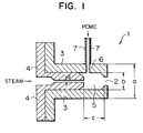
- Fig. 1 is a cross-sectional view of a mixing nozzle used in Examples 1 to 5.
- Fig. 2 is a schematic view of an apparatus used for obtaining a polycarbonate powder having a high bulk density in Examples 7 to 22.
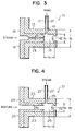
- Fig. 3 is a cross-sectional view of a first mixing nozzle used in Examples 7 to 22.
- Fig. 4 is a cross-sectional view of a second mixing nozzle used in Examples 7 to 22.
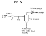
- Fig. 5 is a schematic view of an apparatus used for obtaining a polycarbonate powder having a high bulk density in Examples 23 to 32.
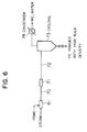
- Fig. 6 is a schematic view of an apparatus used for obtaining a polycarbonate powder having a high bulk density in Examples 33 to 40.
- the polycarbonate concentration in an organic solvent solution of a polycarbonate is 3 to 45 % by weight (to be abbreviated as wt% hereinafter) as described above.
- the reason for the restriction of the polycarbonate concentration to 3 to 45 wt% is that when it is less than 3 wt%, the productivity of a polycarbonate powder is too low, and that when it exceeds 45 wt%, the fluidity of the organic solvent solution is too low to introduce the organic solvent solution into a mixing nozzle.
- the above polycarbonate is not specially limited in kind, and it can be selected from a variety of polycarbonates obtained from reactions of dihydric phenols with phosgene or carbonate ester compounds.
- Examples of the dihydric phenols and carbonate ester compounds are as follows.
- the organic solvent is not specially limited, either, if it can dissolve a polycarbonate and can be evaporated and removed with steam. Methylene chloride is preferred as this organic solvent, while the organic solvent can be also selected from chloroform, carbon tetrachloride, dioxane and tetrahydrofuran. These organic solvents may be used alone or as a mixture.
- Process I the above organic solvent solution and steam are introduced into a mixing nozzle and a polycarbonate is recovered as a powder from a mixture ejected from the mixing nozzle.
- the organic solvent solution and steam are introduced into the mixing nozzle such that the ratio (W S /W O ) of the weight of steam (W S )/the weight of the organic solvent (W O ) in the organic solvent solution is 1/10 to 1/5, as described above.
- the reason for the limitation of W S /W O to 1/10 to 1/5 is that when W S /W O is smaller than 1/10, the amount of a residual organic solvent in the resultant polycarbonate powder is too large and that when W S /W O is larger than 1/5, the resultant polycarbonate powder has too low a bulk density.
- the W S /W O is preferably 1/8 to 1/6.
- steam it is preferred to use steam having a pressure (pressure at the time of introduction into the nozzle) of 1 to 100 kg/cm2 and a temperature of 100 to 310° C.
- the mixing nozzle into which the organic solvent solution and steam are introduced may have any form, while it preferably has an ejector structure.
- the polycarbonate can be recovered from a mixture ejected from the mixing nozzle, for example, by introducing the ejected mixture into a separator such as a gas-solid separating cyclone through a tubing and separating (recovering) the polycarbonate with this separator.
- a separator such as a gas-solid separating cyclone
- the tubing connecting the mixing nozzle and the separator may be any one of a straight tubing and a curved tubing.
- the tubing preferably has a diameter (inner diameter) of 5 mm to 25 cm and a length of 50 cm to 1,000 m.
- the ratio (L/D) of the tubing length (L) to the tubing diameter (inner diameter D) is preferably 100 to 10,000. When this ratio is less than 100, the evaporation of the organic solvent is insufficient. When it exceeds 10,000, the pressure drop is so large that a high-pressure steam is required as the steam which is to be introduced into the mixing nozzle.
- Process I when the organic solvent solution of a polycarbonate and steam are introduced into the mixing nozzle and the polycarbonate is recovered as a powder from a mixture ejected from the mixing nozzle, the polycarbonate concentration in the organic solvent solution is defined as described above and the W S /W O at the introduction time is defined as described above, whereby there can be facilely obtained a polycarbonate powder of which bulk density is high and the residual solvent amount is small.
- Process I can be also applied as part of the step for producing a polycarbonate by an interfacial polycondensation method.
- the organic solvent solution of a polycarbonate which is to be mixed with steam there is used an organic solvent solution of a polycarbonate obtained by subjecting an emulsion obtained by an interfacial polycondensation reaction to washing and separation procedures.
- the organic solvent solution used in Process II is the same organic solvent solution having a polycarbonate concentration of 3 to 45 wt% as that in Process I.
- the reason for the restriction of the lower limit of the polycarbonate concentration to 3 wt% is that when it is less than 3 wt%, the productivity of a polycarbonate powder is too low.
- the reason for the restriction of the upper limit of the polycarbonate concentration to 45 wt% is that when it exceeds 45 wt%, the fluidity of the organic solvent solution is too low to introduce the organic solvent solution into a mixing nozzle (this mixing nozzle used in Process II is sometimes referred to as first mixing nozzle hereinafter).
- the polycarbonate concentration is particularly preferably 10 to 30 wt.%.
- the above polycarbonate is not specially limited in kind, and it can be selected from a variety of polycarbonates obtained from reactions of dihydric phenols with phosgene or carbonate ester compounds. Specific examples of these dihydric phenols and carbonate compounds are various dihydric phenols and various carbonate esters described as examples with regard to Process I.
- the organic solvent is not specially limited, either, if it can dissolve a polycarbonate and can be evaporated and removed with steam.
- Methylene chloride is preferred as this organic solvent, while the organic solvent can be also selected from ethylene chloride, chloroform, carbon tetrachloride, dioxane and tetrahydrofuran as described in Process I. These organic solvents may be used alone or as a mixture.
- the above organic solvent solution and steam in an amount of 1/20 to 1/8 of the weight (to be sometimes referred to as W O1 hereinafter) of the organic solvent in the organic solvent solution are introduced into the first mixing nozzle.
- the reason for the restriction of the lower limit of the weight (to be sometimes referred to as W S1 ) of the steam which is introduced into the first mixing nozzle to 1/20 of W O1 is that when W S1 is less than 1/20 of W O1 , the removal of the organic solvent by evaporation is insufficient for precipitating a polycarbonate from the organic solvent solution.
- the reason for the restriction of the upper limit of W S1 to 1/8 of W O1 is that when W S1 is greater than 1/8 of W O1 , the bulk density of the finally obtained polycarbonate is too low.
- the pressure of the steam which is to be introduced into the first mixing nozzle is preferably 1 to 100 kg/cm2, particularly preferably 3 to 80 kg/cm2.
- pressure at the time of introduction into the nozzle is preferably 1 to 100 kg/cm2, particularly preferably 3 to 80 kg/cm2.
- the pressure of the steam is less than 1 kg/cm2, there is obtained no mixing rate necessary for mixing the organic solvent solution and the steam.
- a high-pressure apparatus is required, and the apparatus cost unnecessarily increases.
- the first mixing nozzle may have any form of mixing nozzles which are generally used, while it preferably has an ejector structure.
- the mixture (to be sometimes referred to as first mixture hereinafter) ejected from the above first mixing nozzle is mixed with steam in an amount of 1/200 to 1/1 of the weight (W O1 ) of the above organic solvent, after a residence time of 0.001 to 1 second, to obtain a second mixture.
- the reason for the restriction of the lower limit of the residence time (to be sometimes referred to as ⁇ hereinafter) to 0.001 second is that when ⁇ is less than 0.001 second, no effect which is to be produced by using steam separately is obtained.
- the reason for the restriction of the upper limit of ⁇ to 1 second is that when ⁇ exceeds 1 second, the polycarbonate is present as an evaporated and dried solid at the time of mixing it with steam so that no effect which is to be produced by mixing it with steam is obtained.
- the reason for the restriction of the lower limit of the weight (to be sometimes referred to as W S2 hereinafter) of the steam used for obtaining the second mixture to 1/200 of W O1 is that when W S2 is less than 1/200 of W O1 , the amount of residual organic solvent in the resultant polycarbonate powder is too large.
- the reason for the restriction of the upper limit of W S2 to 1/1 of W O1 is that even if W S2 is increased to more than 1/1 of W O1 , the resultant polycarbonate powder shows no change in the bulk density and the amount of residual organic solvent so that the amount of the steam is unnecessarily large.
- the second mixture can be obtained, for example, by introducing the first mixture ejected from the first mixing nozzle, into the second mixing nozzle through a tubing to satisfy the above-described residence time and introducing, together with the first mixture, the above-described predetermined amount of steam into the second mixing nozzle.
- the second mixing nozzle may also have any form of generally used mixing nozzle, while it preferably has an ejector structure.
- the second mixture can be also obtained by connecting the first mixing nozzle and a separator to be described later through a tubing, providing a predetermined position of the tubing, i.e., a position where the mixture (first mixture) ejected from the first mixing nozzle satisfies the residence time of 0.001 to 1 second, with another tubing for feeding steam, and mixing the first mixture and the above-described predetermined amount of steam in this position.
- the polycarbonate is recovered as a powder from the second mixture obtained as described above.
- This recovery can be carried out, for example, by introducing the second mixture into a separator such as a gas-solid separating cyclone through a tubing and recovering the polycarbonate with this separator.
- the tubing for introducing the second mixture into the separator may be a straight or curved tubing, while it is required to be long enough to secure the residence time required for the evaporation and drying of the polycarbonate and it is also required to be long enough to compensate the tubing pressure loss relative to the pressure of the steam used.
- the steam and a vapor of the organic solvent can be recovered by condensing them after the recovery of the polycarbonate powder.
- the polycarbonate powder obtained as described above is a powder of which the bulk density is high and the amount of residual organic solvent is small. Further, when the polycarbonate powder is produced by Process II, the polycarbonate powder shows small changes in properties (bulk density and amount of residual solvent) even if the amount of the treated organic solvent solution of the polycarbonate varies. Therefore, when the so-obtained polycarbonate powder is subjected to post treatments such as a drying or granulation step and the subsequent molding thereof in the form of pellets, the mechanical disadvantages (e.g., that the post treatment can be no longer carried out due to a change in the properties of the polycarbonate powder) can be prevented. On the other hand, the polycarbonate powder has a high bulk density, and the apparatus used for the post treatment is hence improved in volume efficiency.
- Process II can be also applied as part of the step for producing a polycarbonate by an interfacial polycondensation method.
- the organic solvent solution of a polycarbonate there is used an organic solvent solution of a polycarbonate obtained by subjecting an emulsion obtained by an interfacial polycondensation reaction to washing and separation procedures.
- the organic solvent solution used in Process III is the same organic solvent solution having a polycarbonate concentration of 3 to 45 wt% as that in each of Processes I and II.
- the reason for the restriction of the lower limit of the polycarbonate concentration to 3 wt% is that when it is less than 3 wt%, the productivity of a polycarbonate powder is too low.
- the reason for the restriction of the upper limit of the polycarbonate concentration to 45 wt% is that when it exceeds 45 wt%, the fluidity of the organic solvent solution is too low to introduce the organic solvent solution into the mixing nozzle.
- the above polycarbonate is not specially limited in kind, and it can be selected from a variety of polycarbonates obtained from reactions of dihydric phenols with phosgene or carbonate ester compounds. Specific examples of these dihydric phenols and carbonate compounds are various dihydric phenols and various carbonate esters described as examples with regard to Process I.
- the organic solvent is not specially limited, either, if it can dissolve a polycarbonate and can be evaporated and removed with steam.
- Methylene chloride is preferred as this organic solvent, while the organic solvent can be also selected from ethylene chloride, chloroform, carbon tetrachloride, dioxane and tetrahydrofuran as described in Process I. These organic solvents may be used alone or as a mixture.
- Process III the above organic solvent solution, steam and a polycarbonate powder are introduced into a mixing nozzle, and the polycarbonate is recovered as a powder from a mixture ejected from the mixing nozzle.
- a steam having a pressure (pressure at the time of introduction into the mixing nozzle) of 1 to 100 kg/cm2 and a temperature of 100 to 310° C.
- the amount of the steam introduced into the mixing nozzle may be the same as that in Process I, i.e., 1/10 to 1/5 of the weight of the organic solvent in the organic solvent solution introduced in the mixing nozzle (this case will be referred to as Combination A with Process I hereinafter), or it may be the same as the amount employed in conventional methods, i.e., greater than 1/5 of the weight of the organic solvent in the organic solvent solution (this case will be referred to as Combination A with Conventional method hereinafter).
- the amount of the introduced steam is less than 1/10, the evaporation of the solvent is insufficient.
- the amount of the steam introduced into the mixing nozzle is particularly preferably 1/10 to 1/1 of the weight of the organic solvent in the organic solvent solution.
- the polycarbonate powder to be introduced into the mixing nozzle may be a polycarbonate powder which has the same quality as, or the different quality from, the polycarbonate dissolved in the above organic solvent solution, while it is preferred to use the same quality polycarbonate powder in view of practical use.
- the polycarbonate powder alone may be introduced through a specialized tubing, while it is practically preferred to introduce it in the state of a mixture thereof with steam.
- the polycarbonate powder can be introduced into the mixing nozzle in a state of a mixture thereof with steam, for example, by a method in which a tubing for feeding the polycarbonate powder is provided somewhere between one end of a tubing for feeding steam (to be sometimes referred to as steam line) into the mixing nozzle and the other end thereof, and steam and the polycarbonate powder are mixed within the steam line.
- a tubing for feeding the polycarbonate powder is provided somewhere between one end of a tubing for feeding steam (to be sometimes referred to as steam line) into the mixing nozzle and the other end thereof, and steam and the polycarbonate powder are mixed within the steam line.
- the amount of the polycarbonate powder introduced into the mixing nozzle is preferably 0.5 to 20 %, particularly preferably 1 to 20 %, of the weight of the polycarbonate in the organic solvent solution introduced into the mixing nozzle.
- the particle diameter of the polycarbonate powder to be introduced into the mixing nozzle is preferably 8 mesh or less and 200 mesh or more. When the above particle diameter exceeds 8 mesh, it is liable to be difficult to feed the polycarbonate powder into the mixing nozzle. When it is less than 200 mesh, it is liable to be difficult to feed the polycarbonate powder into the mixing nozzle.
- the mixing nozzle into which the organic solvent solution, steam and polycarbonate powder are introduced may have any form, while it preferably has an ejector structure.
- the recovery of the polycarbonate from the mixture ejected from the mixing nozzle can be carried out, for example, by introducing the ejected mixture into a separator such as a gas-solid separating cyclone through a tubing and separating (recovering) the polycarbonate with the separator.
- the tubing connecting the mixing nozzle and the separator may be any one of a straight tubing and a curved tubing.
- the tubing preferably has a diameter (inner diameter) of 5 mm to 25 cm and a length of 50 cm to 1,000 m.
- the ratio (L/D) of the tubing length (L) to the tubing diameter (inner diameter D) is preferably 100 to 10,000. When this ratio is less than 100, the evaporation of the organic solvent is insufficient. When it exceeds 10,000, the pressure drop is so large that a high-pressure steam is required as the steam to be introduced into the mixing nozzle.
- the polycarbonate which is finally obtained as above has the form of granules (the polycarbonate in the form of granules, obtained by Process III, is generally called polycarbonate powder in the present invention), and it has a higher bulk density than a polycarbonate powder obtained by a conventional method using a mixing nozzle or by Process I. Further, the amount of residual solvent in the polycarbonate powder obtained by Process III is as small as, or less than, the amount of residual solvent in the polycarbonate powder obtained by any one of the above conventional method and Process I.
- Process III can be also applied as part of the step for producing a polycarbonate by an interfacial polycondensation method.
- the organic solvent solution of a polycarbonate there is used an organic solvent solution of a polycarbonate obtained by subjecting an emulsion obtained by an interfacial polycondensation reaction to washing and separation procedures.
- the organic solvent solution used in Process IV is the same organic solvent solution having a polycarbonate concentration of 3 to 45 wt% as that in each of Processes I, II and III.
- the reason for the restriction of the lower limit of the polycarbonate concentration to 3 wt% is that when it is less than 3 wt%, the productivity of a polycarbonate powder is too low.
- the reason for the restriction of the upper limit of the polycarbonate concentration to 45 wt% is that when it exceeds 45 wt%, the fluidity of the organic solvent solution is too low to introduce the organic solvent solution into the mixing nozzle.
- the polycarbonate concentration is particularly preferably 10 to 30 wt%.
- the above polycarbonate is not specially limited in kind, and it can be selected from a variety of polycarbonates obtained from reactions of dihydric phenols with phosgene or carbonate ester compounds. Specific examples of these dihydric phenols and carbonate compounds are various dihydric phenols and various carbonate esters described as examples with regard to Process I.
- the organic solvent is not specially limited, either, if it can dissolve a polycarbonate and can be evaporated and removed with steam.
- Methylene chloride is preferred as this organic solvent, while the organic solvent can be also selected from ethylene chloride, chloroform, carbon tetrachloride, dioxane and tetrahydrofuran as described in Process I. These organic solvents may be used alone or as a mixture.
- Process IV the above organic solvent solution, steam and a polycarbonate powder are introduced into a mixing nozzle, and the mixture ejected from the mixing nozzle is introduced into a mixer.
- the above steam introduced into the mixing nozzle it is preferred to use a steam having a pressure (pressure at the time of introduction into the mixing nozzle) of 1 to 100 kg/cm2 and a temperature of 100 to 310° C.
- the amount of the steam introduced into the mixing nozzle may be the same as that in Process I, i.e., 1/10 to 1/5 of the weight of the organic solvent in the organic solvent solution introduced into the mixing nozzle (this case will be referred to as Combination B with Process I hereinafter), or it may be the same as the amount employed in conventional methods, i.e., greater than 1/5 of the weight of the organic solvent in the organic solvent solution (this case will be referred to as Combination B with Conventional method hereinafter).
- the amount of the introduced steam is less than 1/10, the evaporation of the solvent is insufficient.
- the amount of the steam introduced into the mixing nozzle is particularly preferably 1/10 to 1/1 of the weight of the organic solvent in the organic solvent solution.
- the mixing nozzle into which the above steam and the above-described organic solvent solution are introduced may have any form, while it particularly preferably has an ejector structure.
- the mixer into which the mixture ejected from the mixing nozzle is introduced may be any one of a dynamic mixer and a static mixer, while a dynamic mixer having crushing capability is preferred.
- a dynamic mixer include a pipe-line homomixer and a homomic line flow supplied by Tokushu Kika Kogyo Co., Ltd., a multi-line mixer supplied by Satake Chemical Equipment MFG., Ltd., and a Komatsu disintegrator supplied by KOMATSU ZENOAH Co.
- Specific examples of the static mixer include a Kenix static mixer, a Sulzer static mixer and a Toray static mixer.
- the position where the mixer is arranged is preferably in a position where L/l* is at least 5, particularly at least 10, in which L is a flow path length from the mixing nozzle to the gas-solid separator and l* is a flow path length from the mixing nozzle to the mixer.
- L means a flow path length from the external end face of the ejecting outlet of the mixing nozzle to the external end face of the inlet of the gas-solid separator.
- l* means a flow path length from the external end face of the ejecting outlet of the mixing nozzle to the internal end face of the intake of the mixer.
- the blade end velocity is preferably 50 to 2,500 m/minute, particularly preferably 100 to 1,500 m/minute.
- the blade end velocity is less than 50 m/minute, the effect on the improvement of the bulk density of the resultant polycarbonate is low as compared with the case where the blade end velocity is 50 to 2,500 m/minute. Even if the mixer is actuated at a rate of over 2,500 m/minute, no further improvement of the bulk density is observed.
- Process IV the mixture outletted from the above mixer is introduced into a gas-solid separator through a tubing, and the polycarbonate powder is recovered with this gas-solid separator.
- the recovery of the polycarbonate powder with the gas-solid separator can be carried out by a conventional method using a general gas-solid separator typified by a gas-solid separating cyclone.
- Each of the above tubing for connecting the mixing nozzle and the mixer and a tubing for connecting the mixer and the gas-solid separator may be any one of a straight tubing and a curved tubing, while the tube diameter (inner diameter) D of each tubing is preferably 5 mm to 25 cm, and the ratio (L/D) of the above flow path L to this tube diameter D is preferably 100 to 10,000. When this ratio is less than 100, the evaporation of the organic solvent is insufficient. When it exceeds 10,000, the pressure drop is so large that a high-pressure steam is required as the steam to be introduced into the mixing nozzle.
- the polycarbonate which is finally obtained as above has the form of granules (the polycarbonate in the form of granules, obtained by Process IV, is generally called polycarbonate powder in the present invention), and it has a higher bulk density than a polycarbonate powder obtained by a conventional method using a mixing nozzle or by Process I when those polycarbonates whose residual amounts of solvent are equivalent are compared. Further, the amount of residual solvent in this polycarbonate powder having a high bulk density is substantially equivalent to the amount of residual solvent in the polycarbonate powder obtained by any one of the above conventional method and Process I.
- Process IV can be also applied as part of the step for producing a polycarbonate by an interfacial polycondensation method.
- the organic solvent solution of a polycarbonate there is used an organic solvent solution of a polycarbonate obtained by subjecting an emulsion obtained by an interfacial polycondensation reaction to washing and separation procedures.
- TOUGHLON A2500 (trade name) supplied by Idemitsu Petrochemical Co., Ltd. as a polycarbonate (to be sometimes referred to as PC hereinafter) was dissolved in methylene chloride (special grade, supplied by Hiroshima Wako Pure Chemical Industries, Ltd., to be some times referred to as MC hereinafter) to prepare a solution of 13 wt% of PC in methylene chloride (to be referred to as PCMC hereinafter).
- a mixing nozzle of which the structure is shown in Fig. 1 was used as the mixing nozzle.
- This mixing nozzle 1 is provided with a first nozzle 3 having an ejector outlet 2 and a second nozzle 4 which is disposed such that the outer wall of an ejection head is brought into contact with the inner wall of the ejection head of the first nozzle 3.
- a mixing chamber 5 is formed in an inner space of the ejection head of the first nozzle 3.
- the ejection head of the first nozzle 3 is provided with a through opening 6 communicating with the mixing chamber 5, and this through opening 6 communicates with a PCMC feed tube 7.
- the ejection head of the first nozzle 3 has an outer diameter, a, of 50 mm
- the mixing chamber 5 has a maximum diameter, b, of 30 mm
- the mixing chamber 5 has a distance, c, of 50 mm from the top of the second nozzle 4 to the end surface of the mixing chamber 5 on the ejector outlet 2 side
- the narrowest portion of the second nozzle in the inner space has a diameter, d, of 5 mm.
- PCMC introduced into the mixing chamber 5 through the PCMC feed tube 7 and the through opening 6 is mixed with a steam introduced into the mixing chamber 5 through the second nozzle 4 to form a mixture, and the mixture is ejected through the ejector outlet 2.
- a mixture ejected from the mixing nozzle 1 was introduced into a cyclone having an internal volume of 0.3 m3 through a stainless steel tubing of which the inner diameter (D) was 10 mm, the tube length (L) was 10 m and L/D was 1,000.
- Table 1 shows the bulk density of the obtained PC powder having a high bulk density and the amount of residual mount thereof (to be referred to as residual MC amount hereinafter). Further, Table 1 also shows the residual MC amount found after the PC powder having a high bulk density was dried at 120°C for 4 hours (to be referred to as after-dry residual MC amount).
- a PC powder having a high bulk density was obtained in the same manner as in Example 1 except that PCMC was introduced into the mixing nozzle 1 at a rate of 215.5 kg/hr and that W S /W MC was changed to 1/7.5.
- Table 1 shows the bulk density, residual MC amount and after-dry residual MC amount of the so-obtained PC powder having a high bulk density.
- a PC powder having a high bulk density was obtained in the same manner as in Example 1 except that PCMC was introduced into the mixing nozzle 1 at a rate of 258.6 kg/hr and that W S /W MC was changed to 1/9.
- Table 1 shows the bulk density, residual MC amount and after-dry residual MC amount of the so-obtained PC powder having a high bulk density.
- a PC powder having a high bulk density was obtained in the same manner as in Example 1 except that the PC concentration in PCMC was changed to 8 wt%, that this PCMC was introduced into the mixing nozzle 1 at a rate of 203.8 kg/hr and that W S /W MC was changed to 1/7.5.
- Table 1 shows the bulk density, residual MC amount and after-dry residual MC amount of the so-obtained PC powder having a high bulk density.
- a PC powder having a high bulk density was obtained in the same manner as in Example 1 except that the PC concentration in PCMC was changed to 25 wt%, that this PCMC was introduced into the mixing nozzle 1 at a rate of 250 kg/hr and that W S /W MC was changed to 1/7.5.
- Table 1 shows the bulk density, residual MC amount and after-dry residual MC amount of the so-obtained PC powder having a high bulk density.
- the mixing nozzle there was used a mixing nozzle which was structurally the same as the mixing nozzle 1 shown in Fig. 1 and in which the ejection head of the first nozzle 3 had a diameter, a, of 150 mm, the mixing chamber 5 had a maximum diameter, b, of 90 mm, the mixing chamber 5 had a distance, c, of 100 mm from the top of the second nozzle 4 to the end surface of the mixing chamber 5 on the ejector outlet 2 side, and the narrowest portion of the second nozzle 2 in the inner space had a diameter, d, of 15 mm.
- PCMC having a PC concentration of 13 wt% and a steam having a pressure of 14 kg/cm2 and a temperature of 195° C were introduced into the mixing nozzle with a diaphragm pump at rates of 1,724 kg/hr and 200 kg/hr, respectively.
- W S /W MC was 1/7.5.
- a mixture ejected from the mixing nozzle was introduced into a cyclone having an internal volume of 2 m3 through a stainless steel tubing of which the inner diameter (D) was 30 mm, the tube length (L) was 30 m and L/D was 1,000.
- Table 1 shows the bulk density, residual MC amount and after-dry residual MC amount of the so-obtained PC powder having a high bulk density.
- a PC powder having a high bulk density was obtained in the same manner as in Example 1 except that PCMC was introduced into the mixing nozzle 1 at a rate of 114.9 kg/hr and that W S /W MC was changed to 1/4.
- Table 1 shows the bulk density, residual MC amount and after-dry residual MC amount of the so-obtained PC powder having a high bulk density.
- a PC powder having a high bulk density was obtained in the same manner as in Example 1 except that PCMC was introduced into the mixing nozzle 1 at a rate of 57.5 kg/hr and that W S /W MC was changed to 1/2.
- Table 1 shows the bulk density, residual MC amount and after-dry residual MC amount of the so-obtained PC powder having a high bulk density.
- a PC powder having a high bulk density was obtained in the same manner as in Example 1 except that PCMC was introduced into the mixing nozzle 1 at a rate of 344.8 kg/hr and that W S /W MC was changed to 1/12.
- Table 1 shows the bulk density, residual MC amount and after-dry residual MC amount of the so-obtained PC powder having a high bulk density.
- Table 1 PC concentration in PCMC *1 (wt%) W S /W MC *2 PC Powder Bulk density (g/cc) Residual MC amount (wtppm) After-dry residual MC amount (wtppm) Ex. 1 13 1/6 0.41 90 ⁇ 10 Ex. 2 13 1/7.5 0.48 90 ⁇ 10 Ex. 3 13 1/9 0.55 100 ⁇ 10 Ex. 4 8 1/7.5 0.50 100 ⁇ 10 Ex. 5 25 1/7.5 0.47 90 ⁇ 10 Ex. 6 13 1/7.5 0.48 90 ⁇ 10 CEx. 1 13 1/4 0.35 90 ⁇ 10 CEx.
- each of the PC powders having a high bulk density obtained in Examples 1 to 6 wherein W S /W MC was set within the limited range of Process I, had a bulk density of 0.41 to 0.55 g/cc. These values are far greater than any bulk density (0.35 - 0.25 g/cc) of the PC powders obtained in Comparative Examples 1 and 2 wherein W S /W MC was made larger than the upper limit of the limited range of Process I.
- the residual MC amount of each of the PC powders having a high bulk density, obtained in Examples 1 to 6, is as small as 90 to 100 wtppm, and these values are equivalent to the residual MC amounts (90 wtppm) of the PC powders obtained in Comparative Examples 1 and 2.
- the PC powder obtained in Comparative Example 3 wherein W S /W MC was made smaller than the lower limit of the limited range of Process 1 has a high bulk density, as high as 0.50 g/cc, whereas the residual MC amount and after-dry residual MC amount are very large.
- FIG. 2 An apparatus shown in Fig. 2 was used, which had a first mixing nozzle 11 into which PCMC and a steam were introduced, a second mixing nozzle 21 into which a mixture ejected from the this first mixing nozzle 11 was introduced through a tubing 20 and a steam was also introduced, and a cyclone into which a mixture (second mixture) ejected from this second mixing nozzle 21 was introduced through a tubing 30.
- a PC powder having a high bulk density was produced in the following manner on the basis of Process II.
- TOUGHLON A2200 (trade name) supplied by Idemitsu Petrochemical Co., Ltd. was used as PC.
- This PC was dissolved in methylene chloride (MC) [special grade, supplied by Hiroshima Wako Pure Chemical Industries, Ltd.] to prepare PCMC having a PC concentration of 15 wt%.
- MC methylene chloride
- the above PCMC and a steam having a pressure of 15 kg/cm2 and a temperature of 200° C were introduced into the mixing nozzle 11 with a diaphragm pump at rates of 140 kg/hr and 10 kg/hr, respectively.
- the weight of the steam (W S1 ) was 1/11.9 as large as the weight of the methylene chloride (W MC ).
- this first mixing nozzle 11 is provided with a first nozzle 13 having an ejector outlet 12 and a second nozzle 14 which is disposed such that the outer wall of an ejection head is brought into contact with the inner wall of the ejection head of the first nozzle 13. And, a mixing chamber 15 is formed in an inner space of the ejection head of the first nozzle 13. Further, the ejection head of the first nozzle 13 is provided with a through opening 16 communicating with the mixing chamber 15, and this through opening 16 communicates with a PCMC feed tube 17.
- the ejection head of the first nozzle 13 has an outer diameter, a1, of 50 mm
- the mixing chamber 15 has a maximum diameter, b1, of 30 mm
- the mixing chamber 15 has a distance, c1, of 50 mm from the top of the second nozzle 14 to the end surface of the mixing chamber 15 on the ejector outlet 12 side
- the narrowest portion of the second nozzle 14 in the inner space has a diameter, d1, of 5 mm
- the ejector outlet 12 has a diameter, e1, of 10 mm.
- a mixture ejected from the first mixing nozzle 11 was introduced into the second mixing nozzle 21 through the tubing 20.
- this tubing 20 a stainless steel tubing having an inner diameter of 10 mm was used, and the length of the tubing 20 was made long enough to secure a mixture residence time, ⁇ , of 0.01 second.
- a steam having a pressure of 15 kg/cm2 and a temperature of 200° C was concurrently introduced into this second mixing nozzle 21 at a rate of 3 kg/hr.
- the weight of the steam (W S2 ) was 1/39.7 as large as the weight of MC (W MC ) introduced into the first mixing nozzle 11.
- this second mixing nozzle 21 is provided with a first nozzle 23 having an ejector outlet 22 and a second nozzle 24 which is disposed such that the outer wall of an ejection head is brought into contact with the inner wall of the ejection head of the first nozzle 23.
- a mixing chamber 25 is formed in an inner space of the ejection head of the first nozzle 23.
- the ejection head of the first nozzle 23 is provided with a through opening 26 communicating with the mixing chamber 25, and this through opening 26 communicates with a steam feed tube 27.
- the ejection head of the first nozzle 23 has an outer diameter, a2, of 50 mm
- the mixing chamber 25 has a maximum diameter, b2, of 30 mm
- the mixing chamber 25 has a distance, c2, of 50 mm from the top of the second nozzle 24 to the end surface of the mixing chamber 25 on the ejector outlet 22 side
- the narrowest portion of the second nozzle 24 in the inner space has a diameter, d2, of 10 mm
- the ejector outlet 22 has a diameter, e2, of 10 mm.
- the mixture introduced from the first mixing nozzle 11 into the second mixing nozzle 24 through the tubing 20 is introduced into the mixing chamber 25 through the second nozzle 24, and in this mixing chamber 25, the mixture is mixed with a steam introduced into the mixing chamber 25 through the steam feed tube 27 and the through opening 27 and ejected through the ejector outlet 22.
- the mixture (second mixture) ejected from the second mixing nozzle 21 was introduced into the cyclone 31 through the tubing 30.
- a PC powder was separated (recovered) with this cyclone 31, and MC and the steam were recovered by condensing them with a condenser 32.
- the apparatus shown in Fig. 2 was operated continuously for 2 hours. During the operation, no troubles such as clogging occurred, and the operation was stably carried out.
- PC powders having a high bulk density were obtained with the apparatus shown in Fig. 2 in the same manner as in Example 7 except that the amounts of PCMC and steam introduced into the first mixing nozzle 11 and the amount of steam introduced into the second mixing nozzle 21 were changed as shown in Table 2 and that the length of the tubing 20 connecting the first mixing nozzle 11 and the second mixing nozzle 21 was properly set such that the residence time, ⁇ , of the mixture showed periods of time as shown in Table 2.
- Table 2 shows the bulk density and residual MC amount of each of the so-obtained PC powders having a high bulk density.
- a PC powder having a high bulk density was obtained with the apparatus shown in Fig. 2 in the same manner as in Example 7 except that PCMC having a PC concentration of 12 wt% was used.
- Table 2 shows the bulk density and residual MC amount of the so-obtained PC powder having a high bulk density.
- a PC powder having a high bulk density was obtained with the apparatus shown in Fig. 2 in the same manner as in Example 7 except that PCMC having a PC concentration of 27 wt% was used.
- Table 2 shows the bulk density and residual MC amount of the so-obtained PC powder having a high bulk density.
- PC powders having a high bulk density were obtained with the apparatus shown in Fig. 2 in the same manner as in Example 7 except that the amounts of PCMC and steam introduced into the first mixing nozzle 11 and the amount of steam introduced into the second mixing nozzle 21 were changed as shown in Table 2.
- the inner diameter of the tubing 20 connecting the first mixing nozzle 11 and the second mixing nozzle 21 was changed to 20 mm in Example 21 or to 35 mm in Example 22 such that the residence time, ⁇ , of the mixture was 0.01 second similarly to Example 7.
- Table 2 shows the bulk density and residual MC amount of each of the so-obtained PC powders.
- a PC powder was obtained with the apparatus shown in Fig. 2 in the same manner as in Example 7 except that no steam was fed to the second mixing nozzle 21 as shown in Table 3.
- Table 3 shows the bulk density and residual MC amount of the so-obtained PC powder.
- a PC powder was obtained with the apparatus shown in Fig. 2 in the same manner as in Example 7 except that the amounts of PCMC and steam introduced into the first mixing nozzle 11 and the amount of steam introduced into the second mixing nozzle 21 were respectively changed as shown in Table 3 such that the amount of steam introduced into the first mixing nozzle 11 and the amount of steam introduced into the second mixing nozzle 21 were outside the limited ranges of Process II.
- the length of the tubing 20 connecting the first mixing nozzle 11 and the second mixing nozzle 21 was properly changed such that the residence time, ⁇ , of the mixture was 0.01 second similarly to Example 7.
- Table 3 shows the bulk density and residual MC amount of the so-obtained PC powder.
- PC powders were obtained with the apparatus shown in Fig. 2 in the same manner as in Example 7 except that the length of the tubing 20 connecting the first mixing nozzle 11 and the second mixing nozzle 21 was changed such that the residence time, ⁇ , of each mixture was set as shown in Table 3.
- Table 3 shows the bulk density and residual MC amount of each of the so-obtained PC powders.
- a PC powder was obtained with the apparatus shown in Fig. 2 in the same manner as in Example 7 except that the amount of PCMC introduced into the first mixing nozzle 11 and the amount of steam introduced into the second mixing nozzle 21 were respectively changed as shown in Table 3 and that the length of the tubing 20 connecting the first mixing nozzle 11 and the second mixing nozzle 21 was changed such that the residence time, ⁇ , of the mixture was 0.0005 second which was outside the limited range of Process II.
- Table 3 shows the bulk density and residual MC amount of the so-obtained PC powder.
- the PC powders having a high bulk density, obtained in Examples 7 to 12 have a bulk density of 0.36 to 0.54 g/cc. These values are greater than the bulk density, 0.05 to 0.35 g/cc, of the PC powders obtained by a conventional method using one mixing nozzle.
- the residual MC amount is as low as 20 to 100 wtppm.
- the amount of the organic solvent solution of PC to be treated is varied in the range of 50 to 900 kg/hr in Examples 7 to 12, while the PC powders having a high bulk density are stably obtained in each Example, and the variations of the properties are small among the obtained PC powders having a high bulk density.
- Comparative Examples 4 to 12 cause difficulties, that is, no PC powder is obtained (Comparative Example 6), not only a PC powder but also MC as a solvent are outletted (Comparative Example 4), the obtained PC powders have a low bulk density (Comparative Examples 5, 7, 8, 9, 11 and 12), and the obtained PC powder shows a high MC residual amount although it has a high bulk density (Comparative Example 10).
- TOUGHLON A2500 (trade name) supplied by Idemitsu Petrochemical Co., Ltd. was used as PC.
- This PC was dissolved in methylene chloride (MC) [special grade, supplied by Hiroshima Wako Pure Chemical Industries, Ltd.] to prepare PCMC having a PC concentration of 13 wt%.
- MC methylene chloride
- the amount (weight per unit hour, having the same meaning hereinafter) of steam introduced into the mixing nozzle 41 was 1/7.5 as large as the weight (weight per unit hour, having the same meaning hereinafter) of MC in PCMC introduced into the mixing nozzle 41, and the amount (weight per unit hour, having the same meaning hereinafter) of PCF introduced into the mixing nozzle 41 was 5 % of the weight of PC in PCMC introduced into the mixing nozzle 41.
- mixing nozzle 41 there was used a mixing nozzle having the same form and the same size as those of the mixing nozzle shown in Fig. 1.
- a mixture ejected from the mixing nozzle 41 was introduced into the cyclone 51 having an internal volume of 0.3 m3 through a stainless steel tubing 50 having an inner diameter (D) of 10 mm, a tube length (L) of 10 m and an L/D of 1,000, as shown in Fig. 5.
- a PC powder was separated (recovered) with this cyclone, and MC and the steam were also recovered by condensing them with a condenser 52.
- PC powders having a high bulk density were obtained with the apparatus shown in Fig. 5 in the same manner as in Example 23 except that the amounts of PCMC and PCF introduced into the mixing nozzle 41 were changed as shown in Table 4.
- Table 4 shows the bulk density and residual MC amount of each of the so-obtained PC powders having a high bulk density.
- PC powder having a high bulk density was obtained with the apparatus shown in Fig. 5 in the same manner as in Example 23 except that PCMC having a PC concentration of 8 wt% was used and that the amounts of this PCMC and PCF introduced into the mixing nozzle 41 were changed to 203.8 kg/hr and 815 g/hr, respectively, as shown in Table 4.
- Table 4 shows the bulk density and residual MC amount of the so-obtained PC powder having a high bulk density.
- a PC powder having a high bulk density was obtained with the apparatus shown in Fig. 5 in the same manner as in Example 23 except that PCMC having a PC concentration of 25 wt% was used and that the amounts of this PCMC and PCF introduced into the mixing nozzle 41 were changed to 250 kg/hr and 3.13 kg/hr, respectively, as shown in Table 4.
- Table 4 shows the bulk density and residual MC amount of the so-obtained PC powder having a high bulk density.
- PC powders having a high bulk density were obtained with the apparatus shown in Fig. 5 in the same manner as in Example 23 except that the amounts of PCMC and PCF introduced into the mixing nozzle 41 were changed as shown in Table 4.
- Table 4 shows the bulk density and residual MC amount of each of the so-obtained PC powders having a high bulk density.
- PC powder one of PC powders having a high bulk density, produced according to Process I
- Example 23 A PC powder (one of PC powders having a high bulk density, produced according to Process I) was obtained with the apparatus shown in Fig. 5 in the same manner as in Example 23 except that no PCF was introduced into the mixing nozzle 41 as shown in Table 5.
- Table 5 shows the bulk density and residual MC amount of the so-obtained PC powder.
- PC powder one of PC powders having a high bulk density, produced according to Process I
- Example 26 A PC powder (one of PC powders having a high bulk density, produced according to Process I) was obtained with the apparatus shown in Fig. 5 in the same manner as in Example 26 except that no PCF was introduced into the mixing nozzle 41 as shown in Table 5.
- Table 5 shows the bulk density and residual MC amount of the so-obtained PC powder.
- PC powder one of PC powders having a high bulk density, produced according to Process I
- Example 29 A PC powder (one of PC powders having a high bulk density, produced according to Process I) was obtained with the apparatus shown in Fig. 5 in the same manner as in Example 29 except that no PCF was introduced into the mixing nozzle 41 as shown in Table 5.
- Table 5 shows the bulk density and residual MC amount of the so-obtained PC powder.
- PC powder one of PC powders having a high bulk density, produced according to Process I
- Example 30 A PC powder (one of PC powders having a high bulk density, produced according to Process I) was obtained with the apparatus shown in Fig. 5 in the same manner as in Example 30 except that no PCF was introduced into the mixing nozzle 41 as shown in Table 5.
- Table 5 shows the bulk density and residual MC amount of the so-obtained PC powder.
- PC powder one of PC powders produced according to conventional methods
- Fig. 5 A PC powder (one of PC powders produced according to conventional methods) was obtained with the apparatus shown in Fig. 5 in the same manner as in Example 31 except that no PCF was introduced into the mixing nozzle 41 as shown in Table 5.
- Table 5 shows the bulk density and residual MC amount of the so-obtained PC powder.
- the PC powders having a high bulk density obtained in Examples 23 to 30 wherein Process I was used as a base and PCF was introduced into the mixing nozzle, have a bulk density of 0.58 to 0.66 g/cc. These values are far greater than the bulk density (0.47 to 0.55 g/cc, see Table 5) of the PC powders obtained in Referential Examples 1 to 4 according to Process I.
- the PC powders having a high bulk density obtained in Examples 31 and 32 wherein the conventional method was used as a base and PCF was introduced into the mixing nozzle, have a bulk density of 0.36 and 0.38 g/cc. These values are far greater than the bulk density (0.25 g/cc) of the PC powder obtained in Comparative Example 5 which is an example of a conventional method.
- the residual MC amount is as small as 80 to 100 wtppm, and these values are equivalent to, or smaller than, the residual MC amounts of the PC powders obtained in Referential Examples 1 to 4 and Comparative Example 13.
- TOUGHLON A2500 (trade name) supplied by Idemitsu Petrochemical Co., Ltd. was used as PC.
- This PC was dissolved in methylene chloride (MC) [special grade, supplied by Hiroshima Wako Pure Chemical Industries, Ltd.] to prepare PCMC having a PC concentration of 13 wt%.
- MC methylene chloride
- the above PCMC and a steam having a pressure of 14 kg/cm2 and a temperature of 195° C were introduced into the mixing nozzle 61 with a diaphragm pump at rates (feed rates) of 215.5 kg/hr and 25 kg/hr, respectively.
- the amount (weight per unit hour, having the same meaning hereinafter) of steam introduced into the mixing nozzle 61 was 1/7.5 as large as the weight (weight per unit hour, having the same meaning hereinafter) of MC in PCMC introduced into the mixing nozzle 61.
- mixing nozzle 61 there was used a mixing nozzle having the same form and the same size as those of the mixing nozzle shown in Fig. 1.
- the mixture ejected from the mixing nozzle 61 was introduced into the dynamic mixer 71 through the tubing 70 having an inner diameter, D, of 10 mm.
- the dynamic mixer 71 there was used a dynamic mixer (trade name: T. K. pipeline homomixer SL model, internal volume 50 cc, four turbine blades, diameter of four turbines 4 cm) supplied by Tokushu Kika Kogyo Co., Ltd., and when it was used, the blade top velocity was set at about 754 m/minute (6,000 rpm).
- the mixture ejected from the dynamic mixer 71 was introduced into the cyclone 73 having an internal volume of 0.3 m3 through the stainless steel tubing 72 having an inner diameter of 10 mm.
- the PC powder was separated (recovered) with this cyclone 73, and MC and the steam were recovered by condensing them with a condenser 74.
- the flow path length l from the mixing nozzle 61 to the dynamic mixer 71 was 0.5 m
- the flow path length L from the mixing nozzle 61 to the gas-solid separator (cyclone 73) was 10 m
- L/l was 20.
- Table 6 shows the bulk density and residual MC amount of the so-obtained PC powder having a high bulk density.
- a PC powder having a high bulk density was obtained with the apparatus shown in Fig. 6 in the same manner as in Example 33 except that PCMC having a PC concentration of 8 wt% and that the amount of this PCMC introduced into the mixing nozzle 61 was changed 203.8 kg/hr.
- Table 6 shows the bulk density and residual MC amount of the so-obtained PC powder having a high bulk density.
- a PC powder having a high bulk density was obtained with the apparatus shown in Fig. 6 in the same manner as in Example 33 except that PCMC having a PC concentration of 25 wt% and that the amount of this PCMC introduced into the mixing nozzle 61 was changed 250 kg/hr.
- Table 6 shows the bulk density and residual MC amount of the so-obtained PC powder having a high bulk density.
- a PC powder having a high bulk density was obtained with the apparatus shown in Fig. 6 in the same manner as in Example 33 except that the blade top velocity was set at about 1,130 m/minute (9,000 rpm) when the dynamic mixer 71 was used.
- Table 6 shows the bulk density and residual MC amount of the so-obtained PC powder having a high bulk density.
- a PC powder having a high bulk density was obtained with the apparatus shown in Fig. 6 in the same manner as in Example 33 except that the blade top velocity was set at about 126 m/minute (1,000 rpm) when the dynamic mixer 71 was used.
- Table 6 shows the bulk density and residual MC amount of the so-obtained PC powder having a high bulk density.
- a PC powder having a high bulk density was obtained in the same manner as in Example 33 except that the dynamic mixer 71 was replaced with a static mixer, a Sulzer static mixer (mixing elements and number thereof: SMV type supplied by Sumitomo Heavy Industries, Ltd., 10 elements).
- the flow path length l from the mixing nozzle 61 to the static mixer was 0.5 m
- the flow path length L from the mixing nozzle 61 to the cyclone 73 was 10 m
- L/l was 20.
- Table 6 shows the bulk density and residual MC amount of the so-obtained PC powder having a high bulk density.
- Table 6 shows the bulk density and residual MC amount of the so-obtained PC powder having a high bulk density.
- a PC powder (one of PC powders having a high bulk density, produced according to Process I) was obtained with an apparatus similar to the apparatus shown in Fig. 6 in the same manner as in Example 33, 34, 35 or 36 except that no dynamic mixer 71 was used and that the mixing nozzle 61 and the cyclone 73 were directly connected through a stainless steel tubing having an inner diameter of 10 mm and a length of 10 m.
- Table 6 shows the bulk density and residual MC amount of each of the above-obtained PC powders.
- a PC powder (one of PC powders produced according to conventional methods) was obtained with an apparatus similar to the apparatus shown in Fig. 6 in the same manner as in Example 40 except that no dynamic mixer 71 was used and that the mixing nozzle 61 and the cyclone 73 were directly connected through a stainless steel tubing having an inner diameter of 10 mm and a length of 10 m.
- Table 6 shows the bulk density and residual MC amount of each of the above-obtained PC powders.
- the PC powders having a high bulk density obtained in Examples 33 to 39 wherein Process I was used as a base and the mixer was used in combination, have a bulk density of 0.53 to 0.65 g/cc. These values are greater than the bulk density values (0.47 - 0.55 g/cc, see Table 6) of the PC powders obtained in Referential Examples 5 to 8 which are examples of Process I.
- the PC powder having a high bulk density, obtained in Example 40 wherein a conventional method was used as a base and the mixer was used in combination has a bulk density of 0.37 g/cc. This value is far greater than the bulk density (0.25 g/cc) of the PC powder obtained in Comparative Example 14 which is an example of a conventional method.
- the residual MC amounts are as low as 90 to 100 wtppm, and these values are substantially equivalent to the residual MC amounts (90 - 100 wtppm) of the PC powders obtained in Referential Examples 5 to 8 and Comparative Example 14.
- any one of Processes I to IV can facilely give a polycarbonate powder having a higher bulk density than any conventional polycarbonate powder without increasing the residual solvent amount.
- the polycarbonate powder having a high bulk density obtained by any one of these Processes, can increase the volume efficiency of apparatus used for post treatments such as drying or storage and can be easily molded into dense pellets.
- a polycarbonate powder of which the bulk density is high and the residual solvent amount is small can be facilely obtained, and the change of properties of the polycarbonate powder is small even if the amount of the organic solvent solution of polycarbonate for treatment varies. Therefore, the polycarbonate powder obtained by Process II can not only improve the volume efficiency of apparatus for carrying out post treatments such as drying, storage, granulation and molding, but also can be stably subjected to post treatments. From this point of view, the productivity of a polycarbonate product can be also improved.
Abstract
Description
- The present invention relates to a process for the production of a polycarbonate powder, and particularly to a process for the production of a polycarbonate powder having a high bulk density.
- The process for the production of a polycarbonate includes a melt polycondensation method (transesterification method) and an interfacial polycondensation method (phosgene method), and the interfacial polycondensation method is industrially preferably employed.
- In the process for the production of a polycarbonate based on the interfacial polycondensation method, an emulsion obtained by an interfacial polycondensation reaction is subjected to washing and separation procedures to obtain an organic solvent solution of a polycarbonate (the solvent is generally methylene chloride). Then, the polycarbonate is isolated (recovered) as a powder or particles from the obtained organic solvent solution. Thereafter, the so-obtained polycarbonate is molded in the form of pellets, or the like, as required.
- As a simple method for recovering a polycarbonate as a powder from an organic solvent solution, there is known a method in which the organic solvent solution and steam are introduced into an ejector nozzle (mixing nozzle), the mixture ejected from the ejector nozzle is introduced through a tubing into a separator, and a polycarbonate powder is recovered with the separator (JP-B-63-1333, JP-B-2-6561 and U. S. Patent3,508,339). For recovering the polycarbonate powder by the above method, the ratio (WS/WO) of the weight of the steam (WS) and the weight of the organic solvent (WO) in the organic solvent solution of the polycarbonate is set to be greater than 1/5, and the steam and the organic solvent solution are introduced into the mixing nozzle.
- The above method has an advantage in that a polycarbonate having a less residual solvent content can be facilely recovered in the form of powder as compared with a method in which a poor solvent is added to an organic solvent solution of a polycarbonate (JP-B-42-14474), a kneader-applied pulverization method taking advantage of the crystallization of an organic solvent solution of a polycarbonate (JP-B-53-15899) or a method in which an organic solvent solution of a polycarbonate is poured into a hot water (Japanese Patent Application No. 60-115625).
- However, in the conventional method in which an organic solvent solution of a polycarbonate is introduced into a mixing nozzle and the polycarbonate is recovered in the form of a powder from a mixture ejected from the mixing nozzle, the obtained polycarbonate has the form of waste thread, and the bulk density thereof is as low as 0.05 to 0.35. Therefore, the volume efficiency of a treating apparatus used for the post treatment for drying or storage of the obtained polycarbonate powder is low. There is hence a problem in that a treating apparatus having a large size is required or that the production adjustment is required to meet the volume of the treating apparatus. Further, a polycarbonate powder having a low bulk density is poor in the mixability with other additives, and dense pellets cannot be obtained when this powder is pelletized.
- It is an object of the present invention to provide a process for the production of a polycarbonate powder having a high bulk density, which can facilely give a polycarbonate powder having a high bulk density and having a less residual solvent content.
- The process of the present invention, which achieves the above object, includes the following processes I to IV.
- I. In a process for the production of a polycarbonate powder having a high bulk density, comprising introducing an organic solvent solution of a polycarbonate and steam into a mixing nozzle and recovering the polycarbonate as a powder from a mixture ejected from the mixing nozzle, the process using, as the organic solvent solution, an organic solvent solution containing 3 to 45 % by weight of the polycarbonate, and employing a ratio of 1/10 to 1/5 as the ratio of the weight of steam/the weight of an organic solvent in the organic solvent solution (this process is referred to as Process I hereinafter).
- II. A process for the production of a polycarbonate powder having a high bulk density, which comprises introducing an organic solvent solution having a polycarbonate concentration of 3 to 45 % by weight and steam in an amount of 1/20 to 1/8 of the weight of an organic solvent in the organic solvent solution, into a mixing nozzle; mixing a mixture ejected from the mixing nozzle with steam in an amount of 1/200 to 1/1 of the weight of the organic solvent in the organic solvent solution, after a residence time of 0.001 to 1 second, to obtain a second mixture; and recovering a polycarbonate as a powder from the second mixture (this process is referred to as Process II hereinafter).
- III. A process for the production of a polycarbonate having a high bulk density, which comprises introducing an organic solvent solution having a polycarbonate concentration of 3 to 45 % by weight, steam and a polycarbonate powder into a mixing nozzle; and recovering a polycarbonate as a powder from a mixture ejected from the mixing nozzle (this process is referred to as Process III hereinafter).
- IV. A process for the production of a polycarbonate having a high bulk density, which comprises introducing an organic solvent solution having a polycarbonate concentration of 3 to 45 % by weight and steam into a mixing nozzle; introducing a mixture ejected from the mixing nozzle, into a mixer directly from the mixing nozzle or through a tubing; introducing a mixture outletted from the mixer into a gas-solid separator through a tubing; and recovering a polycarbonate from the gas-solid separator (this process is referred to as Process IV hereinafter).
- Fig. 1 is a cross-sectional view of a mixing nozzle used in Examples 1 to 5. Fig. 2 is a schematic view of an apparatus used for obtaining a polycarbonate powder having a high bulk density in Examples 7 to 22. Fig. 3 is a cross-sectional view of a first mixing nozzle used in Examples 7 to 22. Fig. 4 is a cross-sectional view of a second mixing nozzle used in Examples 7 to 22. Fig. 5 is a schematic view of an apparatus used for obtaining a polycarbonate powder having a high bulk density in Examples 23 to 32. Fig. 6 is a schematic view of an apparatus used for obtaining a polycarbonate powder having a high bulk density in Examples 33 to 40.
- Each of the Processes I to IV of the present invention will be detailed hereinafter.
- The polycarbonate concentration in an organic solvent solution of a polycarbonate (to be sometimes simply referred to as organic solvent solution hereinafter) is 3 to 45 % by weight (to be abbreviated as wt% hereinafter) as described above. The reason for the restriction of the polycarbonate concentration to 3 to 45 wt% is that when it is less than 3 wt%, the productivity of a polycarbonate powder is too low, and that when it exceeds 45 wt%, the fluidity of the organic solvent solution is too low to introduce the organic solvent solution into a mixing nozzle.
- The above polycarbonate is not specially limited in kind, and it can be selected from a variety of polycarbonates obtained from reactions of dihydric phenols with phosgene or carbonate ester compounds. Examples of the dihydric phenols and carbonate ester compounds are as follows.
- (1) Dihydric phenols
Dihydroxyarylalkanes such as 2,2'-bis(4-hydroxyphenyl)propane (bisphenol A), bis(4-hydroxyphenyl)methane, bis(4-hydroxyphenyl)phenylmethane, bis(4-hydroxyphenyl)naphthylmethane, bis(4-hydroxyphenyl)-(4-isopropylphenyl)methane, diphenyl-bis(4-hydroxyphenyl)methane, bis(3,5-dichloro-4-hydroxyphenyl)methane, bis(3,5-dimethyl-4-hydroxyphenyl)methane, 1,1-bis(4-hydroxyphenyl)ethane, 1-naphthyl-1,1-bis(4-hydroxyphenyl)ethane, 1-phenyl-1,1-bis(4-hydroxyphenyl)ethane, 1,2-bis(4-hydroxyphenyl)ethane, 2-methyl-1,1-bis(4-hydroxyphenyl)propane, 2,2,-bis(3,5-dimethyl-4-hydroxyphenyl)propane, 1-ethyl-1,1-bis(4-hydroxyphenyl)propane, 2,2-bis(3,5-dichloro-4-hydroxyphenyl)propane, 2,2-bis(3,5-dibromo-4-hydroxyphenyl)propane, 2,2-bis(3,5-dichloro-4-hydroxyphenyl)propane, 2,2-bis(3-methyl-4-hydroxyphenyl)propane, 2,2-bis(3-fluoro-4-hydroxyphenyl)propane, 1,1-bis(4-hydroxyphenyl)butane, 3,2-bis(4-hydroxyphenyl)butane, 1,4-bis(4-hydroxyphenyl)butane, 2,2-bis(4-hydroxyphenyl)pentane, 4-methyl-2,2-bis(4-hydroxyphenyl)pentane, 1,1-bis(4-hydroxyphenyl)-cyclohexane, 1,1-bis(3,4-dichloro-4-hydroxyphenyl)cyclohexane, 2,2-bis(4-hydroxyphenyl)hexane, 4,4-bis(4-hydroxyphenyl)heptane, 2,2-bis(4-hydroxyphenyl)nonane, 1,10-bis(4-hydroxyphenyl)decane and 1,1-bis(4-hydroxyphenyl)cyclododecane; dihdyroxyarylsulfones such as bis(4-hydroxyphenyl)sulfone, bis(3,5-dimethyl-4-hydroxyphenyl)sulfone and bis(3-chloro-4-hydroxyphenyl)sulfone; dihydroxyaryl ethers such as bis(4-hydroxyphenyl)ether and bis(3,5-dimethyl-4-hydroxyphenyl)ether; dihydroxyarylketones such as 4,4'-dihydroxybenzophenone and 3,3',5,5'-tetramethyl-4,4-dihydroxybenzophenone; dihydroxyarylsulfides such as bis(4-hydroxy-phenyl)sulfide, bis(3-methyl-4-hydroxyphenyl)-sulfide and bis(3,5-dimethyl-4-hydroxyphenyl)-sulfide; dihydroxyarylsulfoxides such as bis(4-hydroxyphenyl)sulfoxide; dihydroxydiphenyls such as 4,4'-dihydroxydiphenyl; dihydroxybenzenes such as hydroquinone, resorcinol and methyl-hydroquinone; and dihydroxynaphthalenes such as 1,5-dihydroxy-naphthalene and 2,6-dihydroxy-naphthalene. - (2) Carbonate ester compounds
Diaryl carbonates such as diphenyl carbonate and dialkyl carbonates such as dimethyl carbonate and diethyl carbonate. - The organic solvent is not specially limited, either, if it can dissolve a polycarbonate and can be evaporated and removed with steam. Methylene chloride is preferred as this organic solvent, while the organic solvent can be also selected from chloroform, carbon tetrachloride, dioxane and tetrahydrofuran. These organic solvents may be used alone or as a mixture.
- In Process I, the above organic solvent solution and steam are introduced into a mixing nozzle and a polycarbonate is recovered as a powder from a mixture ejected from the mixing nozzle.
- In this case, the organic solvent solution and steam are introduced into the mixing nozzle such that the ratio (WS/WO) of the weight of steam (WS)/the weight of the organic solvent (WO) in the organic solvent solution is 1/10 to 1/5, as described above. The reason for the limitation of WS/WO to 1/10 to 1/5 is that when WS/WO is smaller than 1/10, the amount of a residual organic solvent in the resultant polycarbonate powder is too large and that when WS/WO is larger than 1/5, the resultant polycarbonate powder has too low a bulk density. The WS/WO is preferably 1/8 to 1/6.
- As the steam, it is preferred to use steam having a pressure (pressure at the time of introduction into the nozzle) of 1 to 100 kg/cm² and a temperature of 100 to 310° C.
- The mixing nozzle into which the organic solvent solution and steam are introduced may have any form, while it preferably has an ejector structure.
- The polycarbonate can be recovered from a mixture ejected from the mixing nozzle, for example, by introducing the ejected mixture into a separator such as a gas-solid separating cyclone through a tubing and separating (recovering) the polycarbonate with this separator. In this case, the tubing connecting the mixing nozzle and the separator may be any one of a straight tubing and a curved tubing. The tubing preferably has a diameter (inner diameter) of 5 mm to 25 cm and a length of 50 cm to 1,000 m. The ratio (L/D) of the tubing length (L) to the tubing diameter (inner diameter D) is preferably 100 to 10,000. When this ratio is less than 100, the evaporation of the organic solvent is insufficient. When it exceeds 10,000, the pressure drop is so large that a high-pressure steam is required as the steam which is to be introduced into the mixing nozzle.
- According to Process I, when the organic solvent solution of a polycarbonate and steam are introduced into the mixing nozzle and the polycarbonate is recovered as a powder from a mixture ejected from the mixing nozzle, the polycarbonate concentration in the organic solvent solution is defined as described above and the WS/WO at the introduction time is defined as described above, whereby there can be facilely obtained a polycarbonate powder of which bulk density is high and the residual solvent amount is small.
- Process I can be also applied as part of the step for producing a polycarbonate by an interfacial polycondensation method. In this case, as the organic solvent solution of a polycarbonate which is to be mixed with steam, there is used an organic solvent solution of a polycarbonate obtained by subjecting an emulsion obtained by an interfacial polycondensation reaction to washing and separation procedures.
- The organic solvent solution used in Process II is the same organic solvent solution having a polycarbonate concentration of 3 to 45 wt% as that in Process I. The reason for the restriction of the lower limit of the polycarbonate concentration to 3 wt% is that when it is less than 3 wt%, the productivity of a polycarbonate powder is too low. The reason for the restriction of the upper limit of the polycarbonate concentration to 45 wt% is that when it exceeds 45 wt%, the fluidity of the organic solvent solution is too low to introduce the organic solvent solution into a mixing nozzle (this mixing nozzle used in Process II is sometimes referred to as first mixing nozzle hereinafter). The polycarbonate concentration is particularly preferably 10 to 30 wt.%.
- The above polycarbonate is not specially limited in kind, and it can be selected from a variety of polycarbonates obtained from reactions of dihydric phenols with phosgene or carbonate ester compounds. Specific examples of these dihydric phenols and carbonate compounds are various dihydric phenols and various carbonate esters described as examples with regard to Process I.
- The organic solvent is not specially limited, either, if it can dissolve a polycarbonate and can be evaporated and removed with steam. Methylene chloride is preferred as this organic solvent, while the organic solvent can be also selected from ethylene chloride, chloroform, carbon tetrachloride, dioxane and tetrahydrofuran as described in Process I. These organic solvents may be used alone or as a mixture.
- In Process II, the above organic solvent solution and steam in an amount of 1/20 to 1/8 of the weight (to be sometimes referred to as WO1 hereinafter) of the organic solvent in the organic solvent solution are introduced into the first mixing nozzle. The reason for the restriction of the lower limit of the weight (to be sometimes referred to as WS1) of the steam which is introduced into the first mixing nozzle to 1/20 of WO1 is that when WS1 is less than 1/20 of WO1, the removal of the organic solvent by evaporation is insufficient for precipitating a polycarbonate from the organic solvent solution. The reason for the restriction of the upper limit of WS1 to 1/8 of WO1 is that when WS1 is greater than 1/8 of WO1, the bulk density of the finally obtained polycarbonate is too low.
- The pressure of the steam which is to be introduced into the first mixing nozzle (pressure at the time of introduction into the nozzle) is preferably 1 to 100 kg/cm², particularly preferably 3 to 80 kg/cm². When the pressure of the steam is less than 1 kg/cm², there is obtained no mixing rate necessary for mixing the organic solvent solution and the steam. Further, for obtaining a steam having a pressure of greater than 100 kg/cm², a high-pressure apparatus is required, and the apparatus cost unnecessarily increases.
- The first mixing nozzle may have any form of mixing nozzles which are generally used, while it preferably has an ejector structure.
- In Process II, the mixture (to be sometimes referred to as first mixture hereinafter) ejected from the above first mixing nozzle is mixed with steam in an amount of 1/200 to 1/1 of the weight (WO1) of the above organic solvent, after a residence time of 0.001 to 1 second, to obtain a second mixture.
- The reason for the restriction of the lower limit of the residence time (to be sometimes referred to as τ hereinafter) to 0.001 second is that when τ is less than 0.001 second, no effect which is to be produced by using steam separately is obtained. The reason for the restriction of the upper limit of τ to 1 second is that when τ exceeds 1 second, the polycarbonate is present as an evaporated and dried solid at the time of mixing it with steam so that no effect which is to be produced by mixing it with steam is obtained.
- The reason for the restriction of the lower limit of the weight (to be sometimes referred to as WS2 hereinafter) of the steam used for obtaining the second mixture to 1/200 of WO1 is that when WS2 is less than 1/200 of WO1, the amount of residual organic solvent in the resultant polycarbonate powder is too large. On the other hand, the reason for the restriction of the upper limit of WS2 to 1/1 of WO1 is that even if WS2 is increased to more than 1/1 of WO1, the resultant polycarbonate powder shows no change in the bulk density and the amount of residual organic solvent so that the amount of the steam is unnecessarily large.
- The second mixture can be obtained, for example, by introducing the first mixture ejected from the first mixing nozzle, into the second mixing nozzle through a tubing to satisfy the above-described residence time and introducing, together with the first mixture, the above-described predetermined amount of steam into the second mixing nozzle. In this case, the second mixing nozzle may also have any form of generally used mixing nozzle, while it preferably has an ejector structure. Further, the second mixture can be also obtained by connecting the first mixing nozzle and a separator to be described later through a tubing, providing a predetermined position of the tubing, i.e., a position where the mixture (first mixture) ejected from the first mixing nozzle satisfies the residence time of 0.001 to 1 second, with another tubing for feeding steam, and mixing the first mixture and the above-described predetermined amount of steam in this position.
- In Process II, the polycarbonate is recovered as a powder from the second mixture obtained as described above. This recovery can be carried out, for example, by introducing the second mixture into a separator such as a gas-solid separating cyclone through a tubing and recovering the polycarbonate with this separator. The tubing for introducing the second mixture into the separator may be a straight or curved tubing, while it is required to be long enough to secure the residence time required for the evaporation and drying of the polycarbonate and it is also required to be long enough to compensate the tubing pressure loss relative to the pressure of the steam used. The steam and a vapor of the organic solvent can be recovered by condensing them after the recovery of the polycarbonate powder.
- The polycarbonate powder obtained as described above is a powder of which the bulk density is high and the amount of residual organic solvent is small. Further, when the polycarbonate powder is produced by Process II, the polycarbonate powder shows small changes in properties (bulk density and amount of residual solvent) even if the amount of the treated organic solvent solution of the polycarbonate varies. Therefore, when the so-obtained polycarbonate powder is subjected to post treatments such as a drying or granulation step and the subsequent molding thereof in the form of pellets, the mechanical disadvantages (e.g., that the post treatment can be no longer carried out due to a change in the properties of the polycarbonate powder) can be prevented. On the other hand, the polycarbonate powder has a high bulk density, and the apparatus used for the post treatment is hence improved in volume efficiency.
- Process II can be also applied as part of the step for producing a polycarbonate by an interfacial polycondensation method. In this case, as the organic solvent solution of a polycarbonate, there is used an organic solvent solution of a polycarbonate obtained by subjecting an emulsion obtained by an interfacial polycondensation reaction to washing and separation procedures.
- The organic solvent solution used in Process III is the same organic solvent solution having a polycarbonate concentration of 3 to 45 wt% as that in each of Processes I and II. The reason for the restriction of the lower limit of the polycarbonate concentration to 3 wt% is that when it is less than 3 wt%, the productivity of a polycarbonate powder is too low. The reason for the restriction of the upper limit of the polycarbonate concentration to 45 wt% is that when it exceeds 45 wt%, the fluidity of the organic solvent solution is too low to introduce the organic solvent solution into the mixing nozzle.
- The above polycarbonate is not specially limited in kind, and it can be selected from a variety of polycarbonates obtained from reactions of dihydric phenols with phosgene or carbonate ester compounds. Specific examples of these dihydric phenols and carbonate compounds are various dihydric phenols and various carbonate esters described as examples with regard to Process I.
- The organic solvent is not specially limited, either, if it can dissolve a polycarbonate and can be evaporated and removed with steam. Methylene chloride is preferred as this organic solvent, while the organic solvent can be also selected from ethylene chloride, chloroform, carbon tetrachloride, dioxane and tetrahydrofuran as described in Process I. These organic solvents may be used alone or as a mixture.
- In Process III, the above organic solvent solution, steam and a polycarbonate powder are introduced into a mixing nozzle, and the polycarbonate is recovered as a powder from a mixture ejected from the mixing nozzle.
- As the above steam, it is preferred to use a steam having a pressure (pressure at the time of introduction into the mixing nozzle) of 1 to 100 kg/cm² and a temperature of 100 to 310° C. The amount of the steam introduced into the mixing nozzle may be the same as that in Process I, i.e., 1/10 to 1/5 of the weight of the organic solvent in the organic solvent solution introduced in the mixing nozzle (this case will be referred to as Combination A with Process I hereinafter), or it may be the same as the amount employed in conventional methods, i.e., greater than 1/5 of the weight of the organic solvent in the organic solvent solution (this case will be referred to as Combination A with Conventional method hereinafter). When the amount of the introduced steam is less than 1/10, the evaporation of the solvent is insufficient. On the other hand, even if a large amount of steam is introduced into the mixing nozzle, the bulk density and the productivity only decrease. Therefore, the amount of the steam introduced into the mixing nozzle is particularly preferably 1/10 to 1/1 of the weight of the organic solvent in the organic solvent solution.
- The polycarbonate powder to be introduced into the mixing nozzle may be a polycarbonate powder which has the same quality as, or the different quality from, the polycarbonate dissolved in the above organic solvent solution, while it is preferred to use the same quality polycarbonate powder in view of practical use. For introducing the above polycarbonate powder into the mixing nozzle, the polycarbonate powder alone may be introduced through a specialized tubing, while it is practically preferred to introduce it in the state of a mixture thereof with steam. The polycarbonate powder can be introduced into the mixing nozzle in a state of a mixture thereof with steam, for example, by a method in which a tubing for feeding the polycarbonate powder is provided somewhere between one end of a tubing for feeding steam (to be sometimes referred to as steam line) into the mixing nozzle and the other end thereof, and steam and the polycarbonate powder are mixed within the steam line.
- The amount of the polycarbonate powder introduced into the mixing nozzle is preferably 0.5 to 20 %, particularly preferably 1 to 20 %, of the weight of the polycarbonate in the organic solvent solution introduced into the mixing nozzle. When the amount of the introduced polycarbonate powder is less than 0.5 %, it is difficult to improve the bulk density of the polycarbonate powder to be finally obtained. Further, even if the polycarbonate powder is introduced into the mixing nozzle in an amount of over 20 %, there is no major difference in the degree of improvement of the bulk density of the polycarbonate powder to be finally obtained. The particle diameter of the polycarbonate powder to be introduced into the mixing nozzle is preferably 8 mesh or less and 200 mesh or more. When the above particle diameter exceeds 8 mesh, it is liable to be difficult to feed the polycarbonate powder into the mixing nozzle. When it is less than 200 mesh, it is liable to be difficult to feed the polycarbonate powder into the mixing nozzle.
- The mixing nozzle into which the organic solvent solution, steam and polycarbonate powder are introduced may have any form, while it preferably has an ejector structure.
- The recovery of the polycarbonate from the mixture ejected from the mixing nozzle can be carried out, for example, by introducing the ejected mixture into a separator such as a gas-solid separating cyclone through a tubing and separating (recovering) the polycarbonate with the separator. In this case, the tubing connecting the mixing nozzle and the separator may be any one of a straight tubing and a curved tubing. The tubing preferably has a diameter (inner diameter) of 5 mm to 25 cm and a length of 50 cm to 1,000 m. The ratio (L/D) of the tubing length (L) to the tubing diameter (inner diameter D) is preferably 100 to 10,000. When this ratio is less than 100, the evaporation of the organic solvent is insufficient. When it exceeds 10,000, the pressure drop is so large that a high-pressure steam is required as the steam to be introduced into the mixing nozzle.
- The polycarbonate which is finally obtained as above has the form of granules (the polycarbonate in the form of granules, obtained by Process III, is generally called polycarbonate powder in the present invention), and it has a higher bulk density than a polycarbonate powder obtained by a conventional method using a mixing nozzle or by Process I. Further, the amount of residual solvent in the polycarbonate powder obtained by Process III is as small as, or less than, the amount of residual solvent in the polycarbonate powder obtained by any one of the above conventional method and Process I.
- Process III can be also applied as part of the step for producing a polycarbonate by an interfacial polycondensation method. In this case, as the organic solvent solution of a polycarbonate, there is used an organic solvent solution of a polycarbonate obtained by subjecting an emulsion obtained by an interfacial polycondensation reaction to washing and separation procedures.
- The organic solvent solution used in Process IV is the same organic solvent solution having a polycarbonate concentration of 3 to 45 wt% as that in each of Processes I, II and III. The reason for the restriction of the lower limit of the polycarbonate concentration to 3 wt% is that when it is less than 3 wt%, the productivity of a polycarbonate powder is too low. The reason for the restriction of the upper limit of the polycarbonate concentration to 45 wt% is that when it exceeds 45 wt%, the fluidity of the organic solvent solution is too low to introduce the organic solvent solution into the mixing nozzle. The polycarbonate concentration is particularly preferably 10 to 30 wt%.
- The above polycarbonate is not specially limited in kind, and it can be selected from a variety of polycarbonates obtained from reactions of dihydric phenols with phosgene or carbonate ester compounds. Specific examples of these dihydric phenols and carbonate compounds are various dihydric phenols and various carbonate esters described as examples with regard to Process I.
- Further, the organic solvent is not specially limited, either, if it can dissolve a polycarbonate and can be evaporated and removed with steam. Methylene chloride is preferred as this organic solvent, while the organic solvent can be also selected from ethylene chloride, chloroform, carbon tetrachloride, dioxane and tetrahydrofuran as described in Process I. These organic solvents may be used alone or as a mixture.
- In Process IV, the above organic solvent solution, steam and a polycarbonate powder are introduced into a mixing nozzle, and the mixture ejected from the mixing nozzle is introduced into a mixer.
- As the above steam introduced into the mixing nozzle, it is preferred to use a steam having a pressure (pressure at the time of introduction into the mixing nozzle) of 1 to 100 kg/cm² and a temperature of 100 to 310° C. The amount of the steam introduced into the mixing nozzle may be the same as that in Process I, i.e., 1/10 to 1/5 of the weight of the organic solvent in the organic solvent solution introduced into the mixing nozzle (this case will be referred to as Combination B with Process I hereinafter), or it may be the same as the amount employed in conventional methods, i.e., greater than 1/5 of the weight of the organic solvent in the organic solvent solution (this case will be referred to as Combination B with Conventional method hereinafter). When the amount of the introduced steam is less than 1/10, the evaporation of the solvent is insufficient. On the other hand, even if a large amount of steam is introduced into the mixing nozzle, the bulk density and the productivity decrease. Therefore, the amount of the steam introduced into the mixing nozzle is particularly preferably 1/10 to 1/1 of the weight of the organic solvent in the organic solvent solution.
- The mixing nozzle into which the above steam and the above-described organic solvent solution are introduced may have any form, while it particularly preferably has an ejector structure.
- The mixer into which the mixture ejected from the mixing nozzle is introduced may be any one of a dynamic mixer and a static mixer, while a dynamic mixer having crushing capability is preferred. Specific examples of the dynamic mixer include a pipe-line homomixer and a homomic line flow supplied by Tokushu Kika Kogyo Co., Ltd., a multi-line mixer supplied by Satake Chemical Equipment MFG., Ltd., and a Komatsu disintegrator supplied by KOMATSU ZENOAH Co. Specific examples of the static mixer include a Kenix static mixer, a Sulzer static mixer and a Toray static mixer.
- The position where the mixer is arranged is preferably in a position where L/l* is at least 5, particularly at least 10, in which L is a flow path length from the mixing nozzle to the gas-solid separator and l* is a flow path length from the mixing nozzle to the mixer. When the mixer is arranged in a position where L/l* is less than 5, the effect on the improvement of the bulk density of the polycarbonate powder is low as compared with a case where L/l* is at least 5. In addition, L means a flow path length from the external end face of the ejecting outlet of the mixing nozzle to the external end face of the inlet of the gas-solid separator. Further, l* means a flow path length from the external end face of the ejecting outlet of the mixing nozzle to the internal end face of the intake of the mixer.
- When the dynamic mixer is used, the blade end velocity is preferably 50 to 2,500 m/minute, particularly preferably 100 to 1,500 m/minute. When the blade end velocity is less than 50 m/minute, the effect on the improvement of the bulk density of the resultant polycarbonate is low as compared with the case where the blade end velocity is 50 to 2,500 m/minute. Even if the mixer is actuated at a rate of over 2,500 m/minute, no further improvement of the bulk density is observed.
- In Process IV, the mixture outletted from the above mixer is introduced into a gas-solid separator through a tubing, and the polycarbonate powder is recovered with this gas-solid separator. The recovery of the polycarbonate powder with the gas-solid separator can be carried out by a conventional method using a general gas-solid separator typified by a gas-solid separating cyclone.
- Each of the above tubing for connecting the mixing nozzle and the mixer and a tubing for connecting the mixer and the gas-solid separator may be any one of a straight tubing and a curved tubing, while the tube diameter (inner diameter) D of each tubing is preferably 5 mm to 25 cm, and the ratio (L/D) of the above flow path L to this tube diameter D is preferably 100 to 10,000. When this ratio is less than 100, the evaporation of the organic solvent is insufficient. When it exceeds 10,000, the pressure drop is so large that a high-pressure steam is required as the steam to be introduced into the mixing nozzle.
- The polycarbonate which is finally obtained as above has the form of granules (the polycarbonate in the form of granules, obtained by Process IV, is generally called polycarbonate powder in the present invention), and it has a higher bulk density than a polycarbonate powder obtained by a conventional method using a mixing nozzle or by Process I when those polycarbonates whose residual amounts of solvent are equivalent are compared. Further, the amount of residual solvent in this polycarbonate powder having a high bulk density is substantially equivalent to the amount of residual solvent in the polycarbonate powder obtained by any one of the above conventional method and Process I.
- Process IV can be also applied as part of the step for producing a polycarbonate by an interfacial polycondensation method. In this case, as the organic solvent solution of a polycarbonate, there is used an organic solvent solution of a polycarbonate obtained by subjecting an emulsion obtained by an interfacial polycondensation reaction to washing and separation procedures.
- Examples of the present invention will be explained hereinafter.
- TOUGHLON A2500 (trade name) supplied by Idemitsu Petrochemical Co., Ltd. as a polycarbonate (to be sometimes referred to as PC hereinafter) was dissolved in methylene chloride (special grade, supplied by Hiroshima Wako Pure Chemical Industries, Ltd., to be some times referred to as MC hereinafter) to prepare a solution of 13 wt% of PC in methylene chloride (to be referred to as PCMC hereinafter).
- Then, the above PCMC and a steam having a pressure of 14 kg/cm² and a temperature of 195° C were concurrently introduced into a mixing nozzle with a diaphragm pump at rates of 172.4 kg/hr and 25 kg/hr, respectively. In this case, the ratio (WS/WMC) of the weight of the steam (WS) to the weight of methylene chloride (WMC) was 1/6.
- A mixing nozzle of which the structure is shown in Fig. 1 was used as the mixing nozzle. This mixing nozzle 1 is provided with a
first nozzle 3 having anejector outlet 2 and asecond nozzle 4 which is disposed such that the outer wall of an ejection head is brought into contact with the inner wall of the ejection head of thefirst nozzle 3. And, a mixingchamber 5 is formed in an inner space of the ejection head of thefirst nozzle 3. Further, the ejection head of thefirst nozzle 3 is provided with a throughopening 6 communicating with the mixingchamber 5, and this throughopening 6 communicates with aPCMC feed tube 7. The ejection head of thefirst nozzle 3 has an outer diameter, a, of 50 mm, the mixingchamber 5 has a maximum diameter, b, of 30 mm, the mixingchamber 5 has a distance, c, of 50 mm from the top of thesecond nozzle 4 to the end surface of the mixingchamber 5 on theejector outlet 2 side, and the narrowest portion of the second nozzle in the inner space has a diameter, d, of 5 mm. In this mixing nozzle 1, PCMC introduced into the mixingchamber 5 through thePCMC feed tube 7 and the throughopening 6 is mixed with a steam introduced into the mixingchamber 5 through thesecond nozzle 4 to form a mixture, and the mixture is ejected through theejector outlet 2. - A mixture ejected from the mixing nozzle 1 was introduced into a cyclone having an internal volume of 0.3 m³ through a stainless steel tubing of which the inner diameter (D) was 10 mm, the tube length (L) was 10 m and L/D was 1,000.
- After the operation for 1 hour, the intended PC powder having a high bulk density was obtained from the bottom of the cyclone. Table 1 shows the bulk density of the obtained PC powder having a high bulk density and the amount of residual mount thereof (to be referred to as residual MC amount hereinafter). Further, Table 1 also shows the residual MC amount found after the PC powder having a high bulk density was dried at 120°C for 4 hours (to be referred to as after-dry residual MC amount).
- A PC powder having a high bulk density was obtained in the same manner as in Example 1 except that PCMC was introduced into the mixing nozzle 1 at a rate of 215.5 kg/hr and that WS/WMC was changed to 1/7.5.
- Table 1 shows the bulk density, residual MC amount and after-dry residual MC amount of the so-obtained PC powder having a high bulk density.
- A PC powder having a high bulk density was obtained in the same manner as in Example 1 except that PCMC was introduced into the mixing nozzle 1 at a rate of 258.6 kg/hr and that WS/WMC was changed to 1/9.
- Table 1 shows the bulk density, residual MC amount and after-dry residual MC amount of the so-obtained PC powder having a high bulk density.
- A PC powder having a high bulk density was obtained in the same manner as in Example 1 except that the PC concentration in PCMC was changed to 8 wt%, that this PCMC was introduced into the mixing nozzle 1 at a rate of 203.8 kg/hr and that WS/WMC was changed to 1/7.5.
- Table 1 shows the bulk density, residual MC amount and after-dry residual MC amount of the so-obtained PC powder having a high bulk density.
- A PC powder having a high bulk density was obtained in the same manner as in Example 1 except that the PC concentration in PCMC was changed to 25 wt%, that this PCMC was introduced into the mixing nozzle 1 at a rate of 250 kg/hr and that WS/WMC was changed to 1/7.5.
- Table 1 shows the bulk density, residual MC amount and after-dry residual MC amount of the so-obtained PC powder having a high bulk density.
- As the mixing nozzle, there was used a mixing nozzle which was structurally the same as the mixing nozzle 1 shown in Fig. 1 and in which the ejection head of the
first nozzle 3 had a diameter, a, of 150 mm, the mixingchamber 5 had a maximum diameter, b, of 90 mm, the mixingchamber 5 had a distance, c, of 100 mm from the top of thesecond nozzle 4 to the end surface of the mixingchamber 5 on theejector outlet 2 side, and the narrowest portion of thesecond nozzle 2 in the inner space had a diameter, d, of 15 mm. And, PCMC having a PC concentration of 13 wt% and a steam having a pressure of 14 kg/cm² and a temperature of 195° C were introduced into the mixing nozzle with a diaphragm pump at rates of 1,724 kg/hr and 200 kg/hr, respectively. In this case, WS/WMC was 1/7.5. - A mixture ejected from the mixing nozzle was introduced into a cyclone having an internal volume of 2 m³ through a stainless steel tubing of which the inner diameter (D) was 30 mm, the tube length (L) was 30 m and L/D was 1,000.
- After the operation for 1 hour, the intended PC powder having a high bulk density was obtained from the bottom of the cyclone. Table 1 shows the bulk density, residual MC amount and after-dry residual MC amount of the so-obtained PC powder having a high bulk density.
- A PC powder having a high bulk density was obtained in the same manner as in Example 1 except that PCMC was introduced into the mixing nozzle 1 at a rate of 114.9 kg/hr and that WS/WMC was changed to 1/4.
- Table 1 shows the bulk density, residual MC amount and after-dry residual MC amount of the so-obtained PC powder having a high bulk density.
- A PC powder having a high bulk density was obtained in the same manner as in Example 1 except that PCMC was introduced into the mixing nozzle 1 at a rate of 57.5 kg/hr and that WS/WMC was changed to 1/2.
- Table 1 shows the bulk density, residual MC amount and after-dry residual MC amount of the so-obtained PC powder having a high bulk density.
- A PC powder having a high bulk density was obtained in the same manner as in Example 1 except that PCMC was introduced into the mixing nozzle 1 at a rate of 344.8 kg/hr and that WS/WMC was changed to 1/12.
- Table 1 shows the bulk density, residual MC amount and after-dry residual MC amount of the so-obtained PC powder having a high bulk density.
Table 1 PC concentration in PCMC *1 (wt%) WS/WMC *2 PC Powder Bulk density (g/cc) Residual MC amount (wtppm) After-dry residual MC amount (wtppm) Ex. 1 13 1/6 0.41 90 <10 Ex. 2 13 1/7.5 0.48 90 <10 Ex. 3 13 1/9 0.55 100 <10 Ex. 4 8 1/7.5 0.50 100 <10 Ex. 5 25 1/7.5 0.47 90 <10 Ex. 6 13 1/7.5 0.48 90 <10 CEx. 1 13 1/4 0.35 90 <10 CEx. 2 13 1/2 0.25 90 <10 CEx. 3 13 1/12 0.50 20,000 500 Ex. = Example, CEx. = Comparative Example *1: Showing PC concentration in PCMC. *2: Showing ratio of weight of steam (WS) introduced into mixing nozzle to weight of methylene chloride (WMC) introduced into mixing nozzle. - As clearly shown in Table 1, each of the PC powders having a high bulk density, obtained in Examples 1 to 6 wherein WS/WMC was set within the limited range of Process I, had a bulk density of 0.41 to 0.55 g/cc. These values are far greater than any bulk density (0.35 - 0.25 g/cc) of the PC powders obtained in Comparative Examples 1 and 2 wherein WS/WMC was made larger than the upper limit of the limited range of Process I.
- Further, the residual MC amount of each of the PC powders having a high bulk density, obtained in Examples 1 to 6, is as small as 90 to 100 wtppm, and these values are equivalent to the residual MC amounts (90 wtppm) of the PC powders obtained in Comparative Examples 1 and 2. Concerning the after-dry residual MC amount, further, all the PC powders obtained in Examples 1 to 6 showed very small amounts, as small as 10 wtppm, similarly to the PC powders obtained in Comparative Examples 1 and 2.
- In addition, the PC powder obtained in Comparative Example 3 wherein WS/WMC was made smaller than the lower limit of the limited range of Process 1 has a high bulk density, as high as 0.50 g/cc, whereas the residual MC amount and after-dry residual MC amount are very large.
- An apparatus shown in Fig. 2 was used, which had a first mixing nozzle 11 into which PCMC and a steam were introduced, a
second mixing nozzle 21 into which a mixture ejected from the this first mixing nozzle 11 was introduced through atubing 20 and a steam was also introduced, and a cyclone into which a mixture (second mixture) ejected from thissecond mixing nozzle 21 was introduced through atubing 30. A PC powder having a high bulk density was produced in the following manner on the basis of Process II. - First, TOUGHLON A2200 (trade name) supplied by Idemitsu Petrochemical Co., Ltd. was used as PC. This PC was dissolved in methylene chloride (MC) [special grade, supplied by Hiroshima Wako Pure Chemical Industries, Ltd.] to prepare PCMC having a PC concentration of 15 wt%.
- Then, the above PCMC and a steam having a pressure of 15 kg/cm² and a temperature of 200° C were introduced into the mixing nozzle 11 with a diaphragm pump at rates of 140 kg/hr and 10 kg/hr, respectively. In this case, the weight of the steam (WS1) was 1/11.9 as large as the weight of the methylene chloride (WMC).
- As the first mixing nozzle 11, there was used a mixing nozzle having a structure shown in Fig. 3. That is, this first mixing nozzle 11 is provided with a
first nozzle 13 having an ejector outlet 12 and asecond nozzle 14 which is disposed such that the outer wall of an ejection head is brought into contact with the inner wall of the ejection head of thefirst nozzle 13. And, a mixingchamber 15 is formed in an inner space of the ejection head of thefirst nozzle 13. Further, the ejection head of thefirst nozzle 13 is provided with a throughopening 16 communicating with the mixingchamber 15, and this through opening 16 communicates with aPCMC feed tube 17. The ejection head of thefirst nozzle 13 has an outer diameter, a₁, of 50 mm, the mixingchamber 15 has a maximum diameter, b₁, of 30 mm, the mixingchamber 15 has a distance, c₁, of 50 mm from the top of thesecond nozzle 14 to the end surface of the mixingchamber 15 on the ejector outlet 12 side, the narrowest portion of thesecond nozzle 14 in the inner space has a diameter, d₁, of 5 mm, and the ejector outlet 12 has a diameter, e₁, of 10 mm. In this mixing nozzle 11, PCMC introduced into the mixingchamber 15 through thePCMC feed tube 17 and the throughopening 16 is mixed with a steam introduced into the mixingchamber 15 through thesecond nozzle 14 to form a mixture, and the mixture is ejected through the ejector outlet 12. - A mixture ejected from the first mixing nozzle 11 was introduced into the
second mixing nozzle 21 through thetubing 20. As thistubing 20, a stainless steel tubing having an inner diameter of 10 mm was used, and the length of thetubing 20 was made long enough to secure a mixture residence time, τ, of 0.01 second. Further, Separately, a steam having a pressure of 15 kg/cm² and a temperature of 200° C was concurrently introduced into thissecond mixing nozzle 21 at a rate of 3 kg/hr. In this case, the weight of the steam (WS2) was 1/39.7 as large as the weight of MC (WMC) introduced into the first mixing nozzle 11. - As the
second mixing nozzle 21, there was used a mixing nozzle having a structure shown in Fig. 4. That is, thissecond mixing nozzle 21 is provided with afirst nozzle 23 having an ejector outlet 22 and asecond nozzle 24 which is disposed such that the outer wall of an ejection head is brought into contact with the inner wall of the ejection head of thefirst nozzle 23. And, a mixingchamber 25 is formed in an inner space of the ejection head of thefirst nozzle 23. Further, the ejection head of thefirst nozzle 23 is provided with a throughopening 26 communicating with the mixingchamber 25, and this through opening 26 communicates with asteam feed tube 27. The ejection head of thefirst nozzle 23 has an outer diameter, a₂, of 50 mm, the mixingchamber 25 has a maximum diameter, b₂, of 30 mm, the mixingchamber 25 has a distance, c₂, of 50 mm from the top of thesecond nozzle 24 to the end surface of the mixingchamber 25 on the ejector outlet 22 side, the narrowest portion of thesecond nozzle 24 in the inner space has a diameter, d₂, of 10 mm, and the ejector outlet 22 has a diameter, e₂, of 10 mm. In this mixingnozzle 21, the mixture introduced from the first mixing nozzle 11 into thesecond mixing nozzle 24 through thetubing 20 is introduced into the mixingchamber 25 through thesecond nozzle 24, and in this mixingchamber 25, the mixture is mixed with a steam introduced into the mixingchamber 25 through thesteam feed tube 27 and the throughopening 27 and ejected through the ejector outlet 22. - The mixture (second mixture) ejected from the
second mixing nozzle 21 was introduced into thecyclone 31 through thetubing 30. A PC powder was separated (recovered) with thiscyclone 31, and MC and the steam were recovered by condensing them with acondenser 32. As thetubing 30, a stainless steel tube having an inner diameter of 10 mm and a length of about 20 mm was used. - The apparatus shown in Fig. 2 was operated continuously for 2 hours. During the operation, no troubles such as clogging occurred, and the operation was stably carried out.
- After the operation for 2 hours, the intended PC powder having a high bulk density was obtained from the bottom of the
cyclone 31. Table 2 shows the bulk density and residual MC amount of the so-obtained PC powder having a high bulk density. - PC powders having a high bulk density were obtained with the apparatus shown in Fig. 2 in the same manner as in Example 7 except that the amounts of PCMC and steam introduced into the first mixing nozzle 11 and the amount of steam introduced into the
second mixing nozzle 21 were changed as shown in Table 2 and that the length of thetubing 20 connecting the first mixing nozzle 11 and thesecond mixing nozzle 21 was properly set such that the residence time, τ, of the mixture showed periods of time as shown in Table 2. - Table 2 shows the bulk density and residual MC amount of each of the so-obtained PC powders having a high bulk density.
- During the operation of the apparatus in Examples 8 to 18, no troubles such as clogging occurred, and the operation was stably carried out.
- A PC powder having a high bulk density was obtained with the apparatus shown in Fig. 2 in the same manner as in Example 7 except that PCMC having a PC concentration of 12 wt% was used. In addition, with a decrease of the PC concentration from 15 wt% (Example 7) to 12 wt%, the amount of steam, WS1 (= 10 kg/hr), introduced into the first mixing nozzle 11 was 1/12.3 as large as the amount (WMC) of MC introduced, and WS2 (= 3 kg/hr) introduced into the
second mixing nozzle 21 was 1/41.1 as large as WMC. - Table 2 shows the bulk density and residual MC amount of the so-obtained PC powder having a high bulk density.
- During the operation, no troubles such as clogging occurred, and the operation was stably carried out.
- A PC powder having a high bulk density was obtained with the apparatus shown in Fig. 2 in the same manner as in Example 7 except that PCMC having a PC concentration of 27 wt% was used. In addition, with an increase of the PC concentration from 15 wt% (Example 7) to 27 wt%, the amount of steam, WS1 (= 10 kg/hr), introduced into the first mixing nozzle 11 was 1/10.2 as large as the amount (WMC) of MC introduced, and WS2 (= 3 kg/hr) introduced into the
second mixing nozzle 21 was 1/34.1 as large as WMC. - Table 2 shows the bulk density and residual MC amount of the so-obtained PC powder having a high bulk density.
- During the operation, no troubles such as clogging occurred, and the operation was stably carried out.
- PC powders having a high bulk density were obtained with the apparatus shown in Fig. 2 in the same manner as in Example 7 except that the amounts of PCMC and steam introduced into the first mixing nozzle 11 and the amount of steam introduced into the
second mixing nozzle 21 were changed as shown in Table 2. However, the inner diameter of thetubing 20 connecting the first mixing nozzle 11 and thesecond mixing nozzle 21 was changed to 20 mm in Example 21 or to 35 mm in Example 22 such that the residence time, τ, of the mixture was 0.01 second similarly to Example 7. - Table 2 shows the bulk density and residual MC amount of each of the so-obtained PC powders.
- During the operation of the apparatus in Examples 21 - 22, no troubles such as clogging occurred, and the operation was stably carried out.
-
- A PC powder was obtained with the apparatus shown in Fig. 2 in the same manner as in Example 7 except that no steam was fed to the
second mixing nozzle 21 as shown in Table 3. - In this case, it was found that both a PC powder and MC (liquid) as a solvent were outletted from the
cyclone 31 side outlet of thetubing 30 connecting thesecond mixing nozzle 21 andcyclone 31, which was unsuitable in practical operation. - Table 3 shows the bulk density and residual MC amount of the so-obtained PC powder.
- Attempts were made to produce PC powders with the apparatus shown in Fig. 2 in the same manner as in Example 7 except that the amount of steam introduced into the first mixing nozzle 11 or the amount of steam introduced into the
second mixing nozzle 21 was set outside the limited range of Process II as shown in Table 3. However, the length of thetubing 20 connecting the first mixing nozzle 11 and thesecond mixing nozzle 21 was properly changed such that the residence time, τ, of each mixture was 0.01 second similarly to Example 7. - Table 3 shows the results.
- A PC powder was obtained with the apparatus shown in Fig. 2 in the same manner as in Example 7 except that the amounts of PCMC and steam introduced into the first mixing nozzle 11 and the amount of steam introduced into the
second mixing nozzle 21 were respectively changed as shown in Table 3 such that the amount of steam introduced into the first mixing nozzle 11 and the amount of steam introduced into thesecond mixing nozzle 21 were outside the limited ranges of Process II. However, the length of thetubing 20 connecting the first mixing nozzle 11 and thesecond mixing nozzle 21 was properly changed such that the residence time, τ, of the mixture was 0.01 second similarly to Example 7. - Table 3 shows the bulk density and residual MC amount of the so-obtained PC powder.
- PC powders were obtained with the apparatus shown in Fig. 2 in the same manner as in Example 7 except that the length of the
tubing 20 connecting the first mixing nozzle 11 and thesecond mixing nozzle 21 was changed such that the residence time, τ, of each mixture was set as shown in Table 3. - Table 3 shows the bulk density and residual MC amount of each of the so-obtained PC powders.
- A PC powder was obtained with the apparatus shown in Fig. 2 in the same manner as in Example 7 except that the amount of PCMC introduced into the first mixing nozzle 11 and the amount of steam introduced into the
second mixing nozzle 21 were respectively changed as shown in Table 3 and that the length of thetubing 20 connecting the first mixing nozzle 11 and thesecond mixing nozzle 21 was changed such that the residence time, τ, of the mixture was 0.0005 second which was outside the limited range of Process II. - Table 3 shows the bulk density and residual MC amount of the so-obtained PC powder.


- As is clearly shown in Table 2, the PC powders having a high bulk density, obtained in Examples 7 to 12, have a bulk density of 0.36 to 0.54 g/cc. These values are greater than the bulk density, 0.05 to 0.35 g/cc, of the PC powders obtained by a conventional method using one mixing nozzle. Further, in the PC powders having a high bulk density, obtained in Examples 7 to 22, the residual MC amount is as low as 20 to 100 wtppm. Further, the amount of the organic solvent solution of PC to be treated is varied in the range of 50 to 900 kg/hr in Examples 7 to 12, while the PC powders having a high bulk density are stably obtained in each Example, and the variations of the properties are small among the obtained PC powders having a high bulk density.
- On the other hand, as is clearly shown in Table 3, Comparative Examples 4 to 12 cause difficulties, that is, no PC powder is obtained (Comparative Example 6), not only a PC powder but also MC as a solvent are outletted (Comparative Example 4), the obtained PC powders have a low bulk density (Comparative Examples 5, 7, 8, 9, 11 and 12), and the obtained PC powder shows a high MC residual amount although it has a high bulk density (Comparative Example 10).
- With an apparatus shown in Fig. 5, which had a mixing
nozzle 41 into which PCMC, a steam and a PC powder (abbreviated as PCF in the drawing) were introduced and acyclone 51 into which a mixture ejected from this mixingnozzle 41 was introduced through atubing 50, a PC powder having a high bulk density was produced in the following manner. - First, TOUGHLON A2500 (trade name) supplied by Idemitsu Petrochemical Co., Ltd. was used as PC. This PC was dissolved in methylene chloride (MC) [special grade, supplied by Hiroshima Wako Pure Chemical Industries, Ltd.] to prepare PCMC having a PC concentration of 13 wt%.
- Then, the above PCMC, a steam having a pressure of 14 kg/cm² and a temperature of 195° C and a PC powder (trade name: TOUGHLON FN2200, supplied by Idemitsu Petrochemical Co., Ltd., particle diameter: 10 - 100 mesh, to be referred to as PCF hereinafter) were introduced into the mixing
nozzle 41 with a diaphragm pump at rates (feed rates) of 215.5 kg/hr, 25 kg/hr and 1.4 kg/hr, respectively. The PCF was fed to a steam line (not shown in Fig. 5) from a hopper (not shown in Fig. 5) of which the internal pressure was maintained at the same level as that of the steam pressure, through a rotary valve (not shown in Fig. 5) and introduced into the mixingnozzle 41 in a state in which the PCF was mixed with steam. - In this case, the amount (weight per unit hour, having the same meaning hereinafter) of steam introduced into the mixing
nozzle 41 was 1/7.5 as large as the weight (weight per unit hour, having the same meaning hereinafter) of MC in PCMC introduced into the mixingnozzle 41, and the amount (weight per unit hour, having the same meaning hereinafter) of PCF introduced into the mixingnozzle 41 was 5 % of the weight of PC in PCMC introduced into the mixingnozzle 41. - As the mixing
nozzle 41, there was used a mixing nozzle having the same form and the same size as those of the mixing nozzle shown in Fig. 1. - A mixture ejected from the mixing
nozzle 41 was introduced into thecyclone 51 having an internal volume of 0.3 m³ through astainless steel tubing 50 having an inner diameter (D) of 10 mm, a tube length (L) of 10 m and an L/D of 1,000, as shown in Fig. 5. A PC powder was separated (recovered) with this cyclone, and MC and the steam were also recovered by condensing them with acondenser 52. - After the apparatus shown in Fig. 5 was operated for 1 hour, the intended PC powder having a high bulk density was obtained from the bottom of the
cyclone 51. Table 4 shows the bulk density and residual MC amount of the so-obtained PC powder having a high bulk density. - PC powders having a high bulk density were obtained with the apparatus shown in Fig. 5 in the same manner as in Example 23 except that the amounts of PCMC and PCF introduced into the mixing
nozzle 41 were changed as shown in Table 4. As shown in Table 4, with changes in the amounts of PCMC and PCF as shown in Table 4, the amount of steam (= 25 kg/hr) introduced into the mixingnozzle 41 was 1/7.5 to 1/9 as large as the weight of MC in PCMC introduced into the mixingnozzle 41, and the amount of PCF introduced into the mixingnozzle 41 was 2 to 10 % of the weight of PC in PCMC introduced into the mixingnozzle 41. - Table 4 shows the bulk density and residual MC amount of each of the so-obtained PC powders having a high bulk density.
- A PC powder having a high bulk density was obtained with the apparatus shown in Fig. 5 in the same manner as in Example 23 except that PCMC having a PC concentration of 8 wt% was used and that the amounts of this PCMC and PCF introduced into the mixing
nozzle 41 were changed to 203.8 kg/hr and 815 g/hr, respectively, as shown in Table 4. In addition, as shown in Table 4, with changes in the PC concentration, the amount of introduced PCMC and the amount of introduced PCF as shown in Table 4, the amount (= 25 kg/hr) of steam introduced into the mixingnozzle 41 was 1/7.5 as large as the weight of MC in PCMC introduced into the mixingnozzle 41, and the amount of PCF introduced into the mixingnozzle 41 was 5 % of the weight of PC in PCMC introduced into the mixingnozzle 41, which values were the same as those in Example 23. - Table 4 shows the bulk density and residual MC amount of the so-obtained PC powder having a high bulk density.
- A PC powder having a high bulk density was obtained with the apparatus shown in Fig. 5 in the same manner as in Example 23 except that PCMC having a PC concentration of 25 wt% was used and that the amounts of this PCMC and PCF introduced into the mixing
nozzle 41 were changed to 250 kg/hr and 3.13 kg/hr, respectively, as shown in Table 4. In addition, as shown in Table 4, with changes in the PC concentration, the amount of introduced PCMC and the amount of introduced PCF as shown in Table 4, the amount (= 25 kg/hr) of steam introduced into the mixingnozzle 41 was 1/7.5 as large as the weight of MC in PCMC introduced into the mixingnozzle 41, and the amount of PCF introduced into the mixingnozzle 41 was 5 % of the weight of PC in PCMC introduced into the mixingnozzle 41, which values were the same as those in Example 23. - Table 4 shows the bulk density and residual MC amount of the so-obtained PC powder having a high bulk density.
- PC powders having a high bulk density were obtained with the apparatus shown in Fig. 5 in the same manner as in Example 23 except that the amounts of PCMC and PCF introduced into the mixing
nozzle 41 were changed as shown in Table 4. In addition, as shown in Table 4, with changes in the amounts of introduced PCMC and introduced PCF as shown in Table 4, the amount (= 25 kg/hr) of steam introduced into the mixingnozzle 41 was 1/2 as large as the weight of MC in PCMC introduced into the mixingnozzle 41, and the amount of PCF introduced into the mixingnozzle 41 was 5 - 10% of the weight of PC in PCMC introduced into the mixingnozzle 41. - Table 4 shows the bulk density and residual MC amount of each of the so-obtained PC powders having a high bulk density.
- A PC powder (one of PC powders having a high bulk density, produced according to Process I) was obtained with the apparatus shown in Fig. 5 in the same manner as in Example 23 except that no PCF was introduced into the mixing
nozzle 41 as shown in Table 5. - Table 5 shows the bulk density and residual MC amount of the so-obtained PC powder.
- A PC powder (one of PC powders having a high bulk density, produced according to Process I) was obtained with the apparatus shown in Fig. 5 in the same manner as in Example 26 except that no PCF was introduced into the mixing
nozzle 41 as shown in Table 5. - Table 5 shows the bulk density and residual MC amount of the so-obtained PC powder.
- A PC powder (one of PC powders having a high bulk density, produced according to Process I) was obtained with the apparatus shown in Fig. 5 in the same manner as in Example 29 except that no PCF was introduced into the mixing
nozzle 41 as shown in Table 5. - Table 5 shows the bulk density and residual MC amount of the so-obtained PC powder.
- A PC powder (one of PC powders having a high bulk density, produced according to Process I) was obtained with the apparatus shown in Fig. 5 in the same manner as in Example 30 except that no PCF was introduced into the mixing
nozzle 41 as shown in Table 5. - Table 5 shows the bulk density and residual MC amount of the so-obtained PC powder.
- A PC powder (one of PC powders produced according to conventional methods) was obtained with the apparatus shown in Fig. 5 in the same manner as in Example 31 except that no PCF was introduced into the mixing
nozzle 41 as shown in Table 5. - Table 5 shows the bulk density and residual MC amount of the so-obtained PC powder.


- As is clearly shown in Table 4, the PC powders having a high bulk density, obtained in Examples 23 to 30 wherein Process I was used as a base and PCF was introduced into the mixing nozzle, have a bulk density of 0.58 to 0.66 g/cc. These values are far greater than the bulk density (0.47 to 0.55 g/cc, see Table 5) of the PC powders obtained in Referential Examples 1 to 4 according to Process I. Further, the PC powders having a high bulk density, obtained in Examples 31 and 32 wherein the conventional method was used as a base and PCF was introduced into the mixing nozzle, have a bulk density of 0.36 and 0.38 g/cc. These values are far greater than the bulk density (0.25 g/cc) of the PC powder obtained in Comparative Example 5 which is an example of a conventional method.
- Further, in the PC powders having a high bulk density, obtained in Examples 23 to 32, the residual MC amount is as small as 80 to 100 wtppm, and these values are equivalent to, or smaller than, the residual MC amounts of the PC powders obtained in Referential Examples 1 to 4 and Comparative Example 13.
- With an apparatus shown in Fig. 6, which had a mixing
nozzle 61 into which PCMC and a steam were introduced, a dynamic mixer into which a mixture ejected from this mixingnozzle 61 was introduced through atubing 70, and acyclone 73 into which a mixture ejected from thisdynamic mixer 71 was introduced through atubing 72, there was produced a PC powder having a high bulk density in the following manner. - First, TOUGHLON A2500 (trade name) supplied by Idemitsu Petrochemical Co., Ltd. was used as PC. This PC was dissolved in methylene chloride (MC) [special grade, supplied by Hiroshima Wako Pure Chemical Industries, Ltd.] to prepare PCMC having a PC concentration of 13 wt%.
- Then, the above PCMC and a steam having a pressure of 14 kg/cm² and a temperature of 195° C were introduced into the mixing
nozzle 61 with a diaphragm pump at rates (feed rates) of 215.5 kg/hr and 25 kg/hr, respectively. In this case, the amount (weight per unit hour, having the same meaning hereinafter) of steam introduced into the mixingnozzle 61 was 1/7.5 as large as the weight (weight per unit hour, having the same meaning hereinafter) of MC in PCMC introduced into the mixingnozzle 61. - As the mixing
nozzle 61, there was used a mixing nozzle having the same form and the same size as those of the mixing nozzle shown in Fig. 1. - The mixture ejected from the mixing
nozzle 61 was introduced into thedynamic mixer 71 through thetubing 70 having an inner diameter, D, of 10 mm. As thedynamic mixer 71, there was used a dynamic mixer (trade name: T. K. pipeline homomixer SL model,internal volume 50 cc, four turbine blades, diameter of fourturbines 4 cm) supplied by Tokushu Kika Kogyo Co., Ltd., and when it was used, the blade top velocity was set at about 754 m/minute (6,000 rpm). - The mixture ejected from the
dynamic mixer 71 was introduced into thecyclone 73 having an internal volume of 0.3 m³ through thestainless steel tubing 72 having an inner diameter of 10 mm. The PC powder was separated (recovered) with thiscyclone 73, and MC and the steam were recovered by condensing them with acondenser 74. - In addition, in this Example 33, the flow path length l from the mixing
nozzle 61 to thedynamic mixer 71 was 0.5 m, the flow path length L from the mixingnozzle 61 to the gas-solid separator (cyclone 73) was 10 m, and L/l was 20. - After the apparatus shown in Fig. 6 was operated for 1 hour, the intended PC powder having a high bulk density was obtained from the bottom of the
cyclone 73. Table 6 shows the bulk density and residual MC amount of the so-obtained PC powder having a high bulk density. - A PC powder having a high bulk density was obtained with the apparatus shown in Fig. 6 in the same manner as in Example 33 except that the amount of PCMC introduced into the mixing
nozzle 61 was changed 258.6 kg/hr. As shown in Table 6, with a change in the amount of introduced PCMC, the amount of steam (= 25 kg/hr) introduced into the mixingnozzle 61 was 1/9 as large as the weight of MC in PCMC introduced into the mixingnozzle 61. - Table 6 shows the bulk density and residual MC amount of the so-obtained PC powder having a high bulk density.
- A PC powder having a high bulk density was obtained with the apparatus shown in Fig. 6 in the same manner as in Example 33 except that PCMC having a PC concentration of 8 wt% and that the amount of this PCMC introduced into the mixing
nozzle 61 was changed 203.8 kg/hr. As shown in Table 6, the amount of steam (= 25 kg/hr) introduced into the mixingnozzle 61 was 1/7.5 as large as the weight of MC in PCMC introduced into the mixingnozzle 61, and this value was the same as that in Example 33. - Table 6 shows the bulk density and residual MC amount of the so-obtained PC powder having a high bulk density.
- A PC powder having a high bulk density was obtained with the apparatus shown in Fig. 6 in the same manner as in Example 33 except that PCMC having a PC concentration of 25 wt% and that the amount of this PCMC introduced into the mixing
nozzle 61 was changed 250 kg/hr. As shown in Table 6, the amount of steam (= 25 kg/hr) introduced into the mixingnozzle 61 was 1/7.5 as large as the weight of MC in PCMC introduced into the mixingnozzle 61, and this value was the same as that in Example 33. - Table 6 shows the bulk density and residual MC amount of the so-obtained PC powder having a high bulk density.
- A PC powder having a high bulk density was obtained with the apparatus shown in Fig. 6 in the same manner as in Example 33 except that the blade top velocity was set at about 1,130 m/minute (9,000 rpm) when the
dynamic mixer 71 was used. - Table 6 shows the bulk density and residual MC amount of the so-obtained PC powder having a high bulk density.
- A PC powder having a high bulk density was obtained with the apparatus shown in Fig. 6 in the same manner as in Example 33 except that the blade top velocity was set at about 126 m/minute (1,000 rpm) when the
dynamic mixer 71 was used. - Table 6 shows the bulk density and residual MC amount of the so-obtained PC powder having a high bulk density.
- A PC powder having a high bulk density was obtained in the same manner as in Example 33 except that the
dynamic mixer 71 was replaced with a static mixer, a Sulzer static mixer (mixing elements and number thereof: SMV type supplied by Sumitomo Heavy Industries, Ltd., 10 elements). In this case, The flow path length l from the mixingnozzle 61 to the static mixer was 0.5 m, the flow path length L from the mixingnozzle 61 to thecyclone 73 was 10 m, and L/l was 20. - Table 6 shows the bulk density and residual MC amount of the so-obtained PC powder having a high bulk density.
- A PC powder having a high bulk density was obtained with the apparatus shown in Fig. 6 in the same manner as in Example 33 except that the amount of PCMC introduced into the mixing
nozzle 61 was changed 57.5 kg/hr. As shown in Table 6, with a change in the amount of introduced PCMC, the amount of steam (= 25 kg/hr) introduced into the mixingnozzle 61 was 1/2 as large as the weight of MC in PCMC introduced into the mixingnozzle 61. - Table 6 shows the bulk density and residual MC amount of the so-obtained PC powder having a high bulk density.
- A PC powder (one of PC powders having a high bulk density, produced according to Process I) was obtained with an apparatus similar to the apparatus shown in Fig. 6 in the same manner as in Example 33, 34, 35 or 36 except that no
dynamic mixer 71 was used and that the mixingnozzle 61 and thecyclone 73 were directly connected through a stainless steel tubing having an inner diameter of 10 mm and a length of 10 m. - Table 6 shows the bulk density and residual MC amount of each of the above-obtained PC powders.
- A PC powder (one of PC powders produced according to conventional methods) was obtained with an apparatus similar to the apparatus shown in Fig. 6 in the same manner as in Example 40 except that no
dynamic mixer 71 was used and that the mixingnozzle 61 and thecyclone 73 were directly connected through a stainless steel tubing having an inner diameter of 10 mm and a length of 10 m. - Table 6 shows the bulk density and residual MC amount of each of the above-obtained PC powders.


- As is clearly shown in Table 6, the PC powders having a high bulk density, obtained in Examples 33 to 39 wherein Process I was used as a base and the mixer was used in combination, have a bulk density of 0.53 to 0.65 g/cc. These values are greater than the bulk density values (0.47 - 0.55 g/cc, see Table 6) of the PC powders obtained in Referential Examples 5 to 8 which are examples of Process I. Further, the PC powder having a high bulk density, obtained in Example 40 wherein a conventional method was used as a base and the mixer was used in combination, has a bulk density of 0.37 g/cc. This value is far greater than the bulk density (0.25 g/cc) of the PC powder obtained in Comparative Example 14 which is an example of a conventional method.
- Further, in the PC powders having a high bulk density, obtained in Examples 33 to 40, the residual MC amounts are as low as 90 to 100 wtppm, and these values are substantially equivalent to the residual MC amounts (90 - 100 wtppm) of the PC powders obtained in Referential Examples 5 to 8 and Comparative Example 14.
- As explained above, any one of Processes I to IV can facilely give a polycarbonate powder having a higher bulk density than any conventional polycarbonate powder without increasing the residual solvent amount.
- And, the polycarbonate powder having a high bulk density, obtained by any one of these Processes, can increase the volume efficiency of apparatus used for post treatments such as drying or storage and can be easily molded into dense pellets.
- Therefore, the productivity of a high-quality polycarbonate product can be improved by working the present invention.
- According to Process II, further, a polycarbonate powder of which the bulk density is high and the residual solvent amount is small can be facilely obtained, and the change of properties of the polycarbonate powder is small even if the amount of the organic solvent solution of polycarbonate for treatment varies. Therefore, the polycarbonate powder obtained by Process II can not only improve the volume efficiency of apparatus for carrying out post treatments such as drying, storage, granulation and molding, but also can be stably subjected to post treatments. From this point of view, the productivity of a polycarbonate product can be also improved.
Claims (27)
- In a process for the production of a polycarbonate powder having a high bulk density, comprising introducing an organic solvent solution of a polycarbonate and steam into a mixing nozzle and recovering the polycarbonate as a powder from a mixture ejected from the mixing nozzle, the process using, as the organic solvent solution, an organic solvent solution containing 3 to 45 % by weight of the polycarbonate, and employing a ratio of 1/10 to 1/5 as the ratio of the weight of steam/the weight of an organic solvent in the organic solvent solution.
- The process of claim 1, wherein WS/WO was set at 1/8 - 1/6.
- The process of claim 1, wherein a methylene chloride solution of a polycarbonate is used as the organic solvent solution.
- The process of claim 1, wherein an organic solvent solution of a polycarbonate, obtained at a step of producing a polycarbonate by an interfacial polycondensation reaction, is used as the organic solvent solution.
- The process of claim 1, wherein a steam having a pressure of 1 to 100 kg/cm² and a temperature of 100 to 310° C when introduced into the mixing nozzle is used as the steam.
- The process of claim 1, wherein the mixture ejected from the mixing nozzle is introduced into a gas-solid separator through a tubing having an inner diameter, D, of 5 mm to 25 cm, a tube length, L, of 50 cm to 1,000 m and a ratio (L/D) of 100 to 10,000 as a ratio of the tube length, L, to the tube diameter (D), and the polycarbonate powder is separated with the gas-solid separator.
- A process for the production of a polycarbonate powder having a high bulk density, which comprises
introducing an organic solvent solution having a polycarbonate concentration of 3 to 45 % by weight and steam in an amount of 1/20 to 1/8 of the weight of an organic solvent in the organic solvent solution, into a mixing nozzle;
mixing a mixture ejected from the mixing nozzle with steam in an amount of 1/200 to 1/1 of the weight of the organic solvent in the organic solvent solution, after a residence time of 0.001 to 1 second, to obtain a second mixture; and
recovering a polycarbonate as a powder from the second mixture. - The process of claim 7, wherein the mixture ejected from the mixing nozzle is introduced into a second mixing nozzle through a tubing, and steam is introduced into the second mixing nozzle, to obtain a second mixture.
- The process of claim 7, wherein a methylene chloride solution of a polycarbonate is used as the organic solvent solution.
- The process of claim 7, wherein an organic solvent solution of a polycarbonate, obtained at a step of producing a polycarbonate by an interfacial polycondensation reaction, is used as the organic solvent solution.
- The process of claim 7, wherein a steam having a pressure of 1 to 100 kg/cm² when introduced into the mixing nozzle is used as the steam.
- A process for the production of a polycarbonate having a high bulk density, which comprises introducing an organic solvent solution having a polycarbonate concentration of 3 to 45 % by weight, steam and a polycarbonate powder into a mixing nozzle; and recovering a polycarbonate as a powder from a mixture ejected from the mixing nozzle.
- The process of claim 12, wherein, for introducing the organic solvent solution, the steam and the polycarbonate powder into the mixing nozzle, the steam and the polycarbonate powder are introduced into the mixing nozzle after brought into a mixed state.
- The process of claim 12, wherein an amount of the steam introduced into the mixing nozzle is 1/10 to 1/1 of a weight of the organic solvent in the organic solvent solution introduced into the mixing nozzle and an amount of the polycarbonate powder introduced into the mixing nozzle is 0.5 to 20 % of the weight of the polycarbonate in the organic solvent solution introduced into the mixing nozzle.
- The process of claim 12, wherein a polycarbonate powder having a particle diameter of 8 mesh or less but 200 mesh or more is used as the polycarbonate powder to be introduced into the mixing nozzle.
- The process of claim 12, wherein a methylene chloride solution of a polycarbonate is used as the organic solvent solution.
- The process of claim 12, wherein an organic solvent solution of a polycarbonate, obtained at a step of producing a polycarbonate by an interfacial polycondensation reaction, is used as the organic solvent solution.
- The process of claim 12, wherein a steam having a pressure of 1 to 100 kg/cm² and a temperature of 100 to 310° C when introduced into the mixing nozzle is used as the steam.
- The process of claim 12, wherein the mixture ejected from the mixing nozzle is introduced into a gas-solid separator through a tubing having an inner diameter, D, of 5 mm to 25 cm, a tube length, L, of 50 cm to 1,000 m and a ratio (L/D) of 100 to 10,000 as a ratio of the tube length, L, to the tube diameter (D), and the polycarbonate powder is separated with the gas-solid separator.
- A process for the production of a polycarbonate having a high bulk density, which comprises introducing an organic solvent solution having a polycarbonate concentration of 3 to 45 % by weight and steam into a mixing nozzle; introducing a mixture ejected from the mixing nozzle, into a mixer directly from the mixing nozzle or through a tubing; introducing a mixture outletted from the mixer, into a gas-solid separator through a tubing; and recovering a polycarbonate with the gas-solid separator.
- The process of claim 20, wherein the mixer is disposed to satisfy that a ratio (L/l*) of a flow path length (L) from the mixing nozzle to the gas-solid separator to a flow path length (l*) from the mixing nozzle to the mixer is at least 5.
- The process of claim 20, wherein a dynamic mixer having a blade top velocity of 50 to 2,500 m/minute is used as the mixer.
- The process of claim 20, wherein a methylene chloride solution of a polycarbonate is used as the organic solvent solution.
- The process of claim 21, wherein an organic solvent solution of a polycarbonate, obtained at a step of producing a polycarbonate by an interfacial polycondensation reaction, is used as the organic solvent solution.
- The process of claim 21, wherein a steam having a pressure of 1 to 100 kg/cm² and a temperature of 100 to 310° C when introduced into the mixing nozzle is used as the steam.
- The process of claim 20, wherein an amount of the steam introduced into the mixing nozzle is 1/10 to 1/1 of a weight of the organic solvent in the organic solvent solution introduced into the mixing nozzle.
- The process of claim 20, wherein the mixing nozzle and the mixer are connected, and the mixer and the gas-solid separator are connected, with tubings having an inner diameter, D, of 5 mm to 25 cm, a tube length, L, of 50 cm to 1,000 m and a ratio (L/D) of 100 to 10,000 as a ratio of the tube length, L, to the inner diameter (D).
Applications Claiming Priority (2)
| Application Number | Priority Date | Filing Date | Title |
|---|---|---|---|
| PCT/JP1992/001193 WO1994006847A1 (en) | 1992-09-18 | 1992-09-18 | Process for producing polycarbonate powder |
| US08/237,027 US5475084A (en) | 1992-09-18 | 1994-05-03 | Process for the production of polycarbonate powder |
Publications (3)
| Publication Number | Publication Date |
|---|---|
| EP0616002A1 true EP0616002A1 (en) | 1994-09-21 |
| EP0616002A4 EP0616002A4 (en) | 1994-12-28 |
| EP0616002B1 EP0616002B1 (en) | 1998-03-04 |
Family
ID=22892050
Family Applications (1)
| Application Number | Title | Priority Date | Filing Date |
|---|---|---|---|
| EP92920000A Expired - Lifetime EP0616002B1 (en) | 1992-09-18 | 1992-09-18 | Process for producing polycarbonate powder |
Country Status (2)
| Country | Link |
|---|---|
| US (1) | US5475084A (en) |
| EP (1) | EP0616002B1 (en) |
Cited By (7)
| Publication number | Priority date | Publication date | Assignee | Title |
|---|---|---|---|---|
| DE19537114A1 (en) * | 1995-10-05 | 1997-04-10 | Bayer Ag | Process for drying polymer powders and agglomerates |
| EP0783011A2 (en) * | 1996-01-05 | 1997-07-09 | Bayer Ag | Method of isolating semi-cristalline polycarbonate powders |
| EP0794043A2 (en) * | 1996-03-06 | 1997-09-10 | Bayer Ag | Process for producing polycarbonate agglomerates |
| WO2001005493A1 (en) * | 1999-07-21 | 2001-01-25 | Universite De Bourgogne | Method for making emulsions and implementing device |
| WO2002044245A1 (en) * | 2000-11-29 | 2002-06-06 | General Electric Company | Resin preheating for steam percipitation jet polycarbonate resin isolation |
| WO2019121248A1 (en) | 2017-12-18 | 2019-06-27 | Covestro Deutschland Ag | Method for producing a polycarbonate using an organic solvent based on chlorinated hydrocarbons |
| US11040320B2 (en) | 2015-03-20 | 2021-06-22 | Sabic Global Technologies B.V. | Drying systems |
Families Citing this family (9)
| Publication number | Priority date | Publication date | Assignee | Title |
|---|---|---|---|---|
| FR2818922B1 (en) * | 2000-12-28 | 2003-10-03 | Atofina | METHOD AND DEVICE FOR IMPLEMENTING A REACTION IN A LIQUID MEDIUM WITH GASEOUS RELEASE |
| CN101754983B (en) | 2007-07-03 | 2012-05-23 | 陶氏环球技术公司 | Process for recovering brominated butadiene polymers from solution |
| EP2207812B1 (en) * | 2007-11-07 | 2011-11-23 | Dow Global Technologies LLC | Partial solvent stripping process for recovering brominated butadiene polymers from solution |
| KR101644212B1 (en) * | 2009-08-04 | 2016-07-29 | 솔레니스 테크놀러지스 케이맨, 엘.피. | Apparatus, system and method for emulsifying oil and water |
| US9618263B2 (en) * | 2012-12-14 | 2017-04-11 | Flash Rockwell Technologies, Llc | Non-thermal drying systems with vacuum throttle flash generators and processing vessels |
| KR102259952B1 (en) | 2014-11-07 | 2021-06-03 | 사빅 글로벌 테크놀러지스 비.브이. | Densified polymer powder, methods of making, methods of using, and articles made therefrom |
| US9796813B1 (en) | 2014-11-25 | 2017-10-24 | Sabic Global Technologies B.V. | Filter alignment in a polycarbonate production process |
| WO2017077446A1 (en) | 2015-11-05 | 2017-05-11 | Sabic Global Technologies B.V. | Process for manufacturing a polymer composition comprising a densified polymer and a conversion material |
| US20190168175A1 (en) * | 2017-12-06 | 2019-06-06 | Larry Baxter | Solids-Producing Siphoning Exchanger |
Citations (1)
| Publication number | Priority date | Publication date | Assignee | Title |
|---|---|---|---|---|
| US4209912A (en) * | 1978-01-16 | 1980-07-01 | General Electric Company | Process and apparatus for the drying of resinous materials |
Family Cites Families (10)
| Publication number | Priority date | Publication date | Assignee | Title |
|---|---|---|---|---|
| NL301688A (en) * | 1962-12-31 | |||
| US3508339A (en) * | 1965-11-30 | 1970-04-28 | Gen Electric | Drying apparatus and process |
| US4074864A (en) * | 1974-10-05 | 1978-02-21 | Idemitsu Kosan Co., Ltd. | Method for producing polycarbonate powder from a polycarbonate solution |
| US4206161A (en) * | 1976-10-18 | 1980-06-03 | Dai Nippon Toryo Co., Ltd. | Method of producing resin powder |
| IT1094162B (en) * | 1978-02-22 | 1985-07-26 | Montedison Spa | CONTINUOUS PROCESS FOR THE RECOVERY OF POLYCARBONATE FROM ITS SOLUTIONS |
| JPS5629890A (en) * | 1979-08-17 | 1981-03-25 | Nec Corp | Differential circuit device |
| EP0256003B1 (en) * | 1981-08-12 | 1991-04-17 | The Dow Chemical Company | Process for converting a thermoplastic polymer into spheroidal agglomerated granules |
| US4546172A (en) * | 1983-01-20 | 1985-10-08 | Mitsubishi Chemical Industries Ltd. | Process for producing polycarbonate resin particles |
| JPS631333A (en) * | 1986-06-18 | 1988-01-06 | Hitachi Ltd | Bisected stator of rotary electric machine |
| JPH0645764B2 (en) * | 1988-06-24 | 1994-06-15 | 日本ペイント株式会社 | Metal pigment composition |
-
1992
- 1992-09-18 EP EP92920000A patent/EP0616002B1/en not_active Expired - Lifetime
-
1994
- 1994-05-03 US US08/237,027 patent/US5475084A/en not_active Expired - Lifetime
Patent Citations (1)
| Publication number | Priority date | Publication date | Assignee | Title |
|---|---|---|---|---|
| US4209912A (en) * | 1978-01-16 | 1980-07-01 | General Electric Company | Process and apparatus for the drying of resinous materials |
Non-Patent Citations (1)
| Title |
|---|
| See also references of WO9406847A1 * |
Cited By (13)
| Publication number | Priority date | Publication date | Assignee | Title |
|---|---|---|---|---|
| DE19537114C2 (en) * | 1995-10-05 | 1998-11-12 | Bayer Ag | Process for drying polymer powders and agglomerates |
| DE19537114A1 (en) * | 1995-10-05 | 1997-04-10 | Bayer Ag | Process for drying polymer powders and agglomerates |
| EP0783011A2 (en) * | 1996-01-05 | 1997-07-09 | Bayer Ag | Method of isolating semi-cristalline polycarbonate powders |
| EP0783011A3 (en) * | 1996-01-05 | 1998-07-08 | Bayer Ag | Method of isolating semi-cristalline polycarbonate powders |
| US5830977A (en) * | 1996-01-05 | 1998-11-03 | Bayer Aktiengesellschaft | Process for the isolation of partially crystalline polycarbonate powder |
| US5852157A (en) * | 1996-03-06 | 1998-12-22 | Bayer Aktiengesellschaft | Process for the production of polycarbonate agglomerate |
| EP0794043A2 (en) * | 1996-03-06 | 1997-09-10 | Bayer Ag | Process for producing polycarbonate agglomerates |
| EP0794043A3 (en) * | 1996-03-06 | 1999-04-07 | Bayer Ag | Process for producing polycarbonate agglomerates |
| WO2001005493A1 (en) * | 1999-07-21 | 2001-01-25 | Universite De Bourgogne | Method for making emulsions and implementing device |
| FR2796568A1 (en) * | 1999-07-21 | 2001-01-26 | Amora Maille | PROCESS FOR PRODUCING EMULSIONS AND DEVICE THEREOF |
| WO2002044245A1 (en) * | 2000-11-29 | 2002-06-06 | General Electric Company | Resin preheating for steam percipitation jet polycarbonate resin isolation |
| US11040320B2 (en) | 2015-03-20 | 2021-06-22 | Sabic Global Technologies B.V. | Drying systems |
| WO2019121248A1 (en) | 2017-12-18 | 2019-06-27 | Covestro Deutschland Ag | Method for producing a polycarbonate using an organic solvent based on chlorinated hydrocarbons |
Also Published As
| Publication number | Publication date |
|---|---|
| US5475084A (en) | 1995-12-12 |
| EP0616002B1 (en) | 1998-03-04 |
| EP0616002A4 (en) | 1994-12-28 |
Similar Documents
| Publication | Publication Date | Title |
|---|---|---|
| EP0616002A1 (en) | Process for producing polycarbonate powder | |
| US5536875A (en) | Enhanced oxidation of organic chemicals | |
| US6440337B1 (en) | Method and apparatus for the formation of particles | |
| US6613128B1 (en) | Twin screw extruder, method of making aromatic polycarbonate using a twin screw extruder, and method of removing volatiles from an aromatic polycarbonate melt | |
| CA2069721A1 (en) | Process for isolating polycarbonates_with co2 under pressure | |
| US4603194A (en) | Isolation of polymer resin from organic solution | |
| EP0116836B1 (en) | Process for producing polycarbonate resin particles | |
| DE60010243T2 (en) | METHOD AND DEVICE FOR PREPARING MONOFONCTIONAL HALOAMEISIC ACID | |
| US5830977A (en) | Process for the isolation of partially crystalline polycarbonate powder | |
| JPH08854B2 (en) | Method for producing high bulk density polycarbonate powder | |
| JPH04298534A (en) | Production of powered polycarbonate | |
| JPH04331237A (en) | Production of polycarbonate powder | |
| JP6668869B2 (en) | Method for manufacturing resin granules | |
| JPH04266930A (en) | Production of high bulk density polycarbonate powder | |
| WO1994006847A1 (en) | Process for producing polycarbonate powder | |
| JP3132915B2 (en) | Method for separating polycarbonate with carbon dioxide | |
| US5760160A (en) | Aromatic polycarbonate resin granule | |
| JP6848362B2 (en) | Lactide recovery method | |
| JP2003526502A (en) | Liquid nozzle with adjustable liquid level | |
| EP0502515A2 (en) | Process for producing polycarbonate resin | |
| JP2002060482A (en) | Method and equipment for manufacturing aromatic polycarbonate | |
| JPH05222174A (en) | Isolation of poly(ester) carbonate from methylene chloride by using carbon dioxide fluid | |
| JPH0892381A (en) | Method for producing aromatic polycarbonate resin particle | |
| EP0963340B1 (en) | Method of producing micron sized sulphur granules | |
| JP5623689B2 (en) | Method for producing polycarbonate resin granules |
Legal Events
| Date | Code | Title | Description |
|---|---|---|---|
| PUAI | Public reference made under article 153(3) epc to a published international application that has entered the european phase |
Free format text: ORIGINAL CODE: 0009012 |
|
| 17P | Request for examination filed |
Effective date: 19940511 |
|
| AK | Designated contracting states |
Kind code of ref document: A1 Designated state(s): BE IT NL |
|
| A4 | Supplementary search report drawn up and despatched | ||
| AK | Designated contracting states |
Kind code of ref document: A4 Designated state(s): BE IT NL |
|
| RAP1 | Party data changed (applicant data changed or rights of an application transferred) |
Owner name: IDEMITSU PETROCHEMICAL CO., LTD. |
|
| 17Q | First examination report despatched |
Effective date: 19960624 |
|
| GRAG | Despatch of communication of intention to grant |
Free format text: ORIGINAL CODE: EPIDOS AGRA |
|
| GRAG | Despatch of communication of intention to grant |
Free format text: ORIGINAL CODE: EPIDOS AGRA |
|
| GRAH | Despatch of communication of intention to grant a patent |
Free format text: ORIGINAL CODE: EPIDOS IGRA |
|
| GRAH | Despatch of communication of intention to grant a patent |
Free format text: ORIGINAL CODE: EPIDOS IGRA |
|
| GRAA | (expected) grant |
Free format text: ORIGINAL CODE: 0009210 |
|
| AK | Designated contracting states |
Kind code of ref document: B1 Designated state(s): BE IT NL |
|
| PG25 | Lapsed in a contracting state [announced via postgrant information from national office to epo] |
Ref country code: IT Free format text: LAPSE BECAUSE OF FAILURE TO SUBMIT A TRANSLATION OF THE DESCRIPTION OR TO PAY THE FEE WITHIN THE PRE;WARNING: LAPSES OF ITALIAN PATENTS WITH EFFECTIVE DATE BEFORE 2007 MAY HAVE OCCURRED AT ANY TIME BEFORE 2007. THE CORRECT EFFECTIVE DATE MAY BE DIFFERENT FROM THE ONE RECORDED.SCRIBED TIME-LIMIT Effective date: 19980304 Ref country code: BE Free format text: LAPSE BECAUSE OF FAILURE TO SUBMIT A TRANSLATION OF THE DESCRIPTION OR TO PAY THE FEE WITHIN THE PRESCRIBED TIME-LIMIT Effective date: 19980304 |
|
| PLBE | No opposition filed within time limit |
Free format text: ORIGINAL CODE: 0009261 |
|
| STAA | Information on the status of an ep patent application or granted ep patent |
Free format text: STATUS: NO OPPOSITION FILED WITHIN TIME LIMIT |
|
| 26N | No opposition filed | ||
| PGFP | Annual fee paid to national office [announced via postgrant information from national office to epo] |
Ref country code: NL Payment date: 20040923 Year of fee payment: 13 |
|
| NLS | Nl: assignments of ep-patents |
Owner name: IDEMITSU KOSAN CO., LTD. |
|
| PG25 | Lapsed in a contracting state [announced via postgrant information from national office to epo] |
Ref country code: NL Free format text: LAPSE BECAUSE OF NON-PAYMENT OF DUE FEES Effective date: 20060401 |
|
| NLV4 | Nl: lapsed or anulled due to non-payment of the annual fee |
Effective date: 20060401 |