EP0614833A2 - A process and a device for conveying articles, particularly for automatic packaging plants - Google Patents
A process and a device for conveying articles, particularly for automatic packaging plants Download PDFInfo
- Publication number
- EP0614833A2 EP0614833A2 EP94102692A EP94102692A EP0614833A2 EP 0614833 A2 EP0614833 A2 EP 0614833A2 EP 94102692 A EP94102692 A EP 94102692A EP 94102692 A EP94102692 A EP 94102692A EP 0614833 A2 EP0614833 A2 EP 0614833A2
- Authority
- EP
- European Patent Office
- Prior art keywords
- articles
- rows
- row
- plate
- flow lines
- Prior art date
- Legal status (The legal status is an assumption and is not a legal conclusion. Google has not performed a legal analysis and makes no representation as to the accuracy of the status listed.)
- Granted
Links
- 238000000034 method Methods 0.000 title claims description 13
- 230000008569 process Effects 0.000 title claims description 11
- 238000004806 packaging method and process Methods 0.000 title abstract description 9
- 238000009825 accumulation Methods 0.000 claims description 8
- 238000013519 translation Methods 0.000 claims description 6
- 230000000694 effects Effects 0.000 claims description 4
- 230000009471 action Effects 0.000 abstract description 8
- 235000009508 confectionery Nutrition 0.000 abstract description 4
- 235000013305 food Nutrition 0.000 abstract description 3
- 230000035508 accumulation Effects 0.000 description 7
- 238000012545 processing Methods 0.000 description 7
- 238000011144 upstream manufacturing Methods 0.000 description 6
- 230000004888 barrier function Effects 0.000 description 4
- 235000015895 biscuits Nutrition 0.000 description 3
- 230000015572 biosynthetic process Effects 0.000 description 2
- 230000002950 deficient Effects 0.000 description 2
- 238000011161 development Methods 0.000 description 2
- 239000002184 metal Substances 0.000 description 2
- 235000011888 snacks Nutrition 0.000 description 2
- 230000001133 acceleration Effects 0.000 description 1
- 230000008901 benefit Effects 0.000 description 1
- 230000001680 brushing effect Effects 0.000 description 1
- 235000019219 chocolate Nutrition 0.000 description 1
- 238000007599 discharging Methods 0.000 description 1
- 230000008030 elimination Effects 0.000 description 1
- 238000003379 elimination reaction Methods 0.000 description 1
- 239000012634 fragment Substances 0.000 description 1
- 230000001788 irregular Effects 0.000 description 1
- 239000005022 packaging material Substances 0.000 description 1
- 238000012856 packing Methods 0.000 description 1
- 238000009877 rendering Methods 0.000 description 1
- 230000033764 rhythmic process Effects 0.000 description 1
- 238000010079 rubber tapping Methods 0.000 description 1
- 239000002689 soil Substances 0.000 description 1
- 230000001360 synchronised effect Effects 0.000 description 1
- 238000012546 transfer Methods 0.000 description 1
Images
Classifications
-
- B—PERFORMING OPERATIONS; TRANSPORTING
- B65—CONVEYING; PACKING; STORING; HANDLING THIN OR FILAMENTARY MATERIAL
- B65G—TRANSPORT OR STORAGE DEVICES, e.g. CONVEYORS FOR LOADING OR TIPPING, SHOP CONVEYOR SYSTEMS OR PNEUMATIC TUBE CONVEYORS
- B65G47/00—Article or material-handling devices associated with conveyors; Methods employing such devices
- B65G47/22—Devices influencing the relative position or the attitude of articles during transit by conveyors
- B65G47/26—Devices influencing the relative position or the attitude of articles during transit by conveyors arranging the articles, e.g. varying spacing between individual articles
-
- B—PERFORMING OPERATIONS; TRANSPORTING
- B65—CONVEYING; PACKING; STORING; HANDLING THIN OR FILAMENTARY MATERIAL
- B65B—MACHINES, APPARATUS OR DEVICES FOR, OR METHODS OF, PACKAGING ARTICLES OR MATERIALS; UNPACKING
- B65B35/00—Supplying, feeding, arranging or orientating articles to be packaged
- B65B35/30—Arranging and feeding articles in groups
- B65B35/44—Arranging and feeding articles in groups by endless belts or chains
-
- B—PERFORMING OPERATIONS; TRANSPORTING
- B65—CONVEYING; PACKING; STORING; HANDLING THIN OR FILAMENTARY MATERIAL
- B65G—TRANSPORT OR STORAGE DEVICES, e.g. CONVEYORS FOR LOADING OR TIPPING, SHOP CONVEYOR SYSTEMS OR PNEUMATIC TUBE CONVEYORS
- B65G47/00—Article or material-handling devices associated with conveyors; Methods employing such devices
- B65G47/02—Devices for feeding articles or materials to conveyors
- B65G47/04—Devices for feeding articles or materials to conveyors for feeding articles
- B65G47/06—Devices for feeding articles or materials to conveyors for feeding articles from a single group of articles arranged in orderly pattern, e.g. workpieces in magazines
- B65G47/08—Devices for feeding articles or materials to conveyors for feeding articles from a single group of articles arranged in orderly pattern, e.g. workpieces in magazines spacing or grouping the articles during feeding
- B65G47/082—Devices for feeding articles or materials to conveyors for feeding articles from a single group of articles arranged in orderly pattern, e.g. workpieces in magazines spacing or grouping the articles during feeding grouping articles in rows
Definitions
- the present invention relates to a process for conveying articles supplied in respective flow lines adjacent to one another.
- the invention has been developed with particular attention to the possible use in the field of plants for automatically packaging products, such as food products, for example confectionery products.
- the source stations can be packaging machines in which products such as snacks, biscuits, etc., packaged in flexible wrappers (flow-packs), are inserted in groups in respective boxes.
- the further processing stations can, for example, be wrapping machines in which each box is in turn inserted in a further wrapping in the form of a flexible wrapper of the flow-pack type.
- the source stations usually supply a conveying line with parallel rows.
- Each source machine supplies a respective row with a flow of articles which, although it is substantially constant, is not completely continuous, owing to the various reasons: for example, temporary stoppages of the source station because of a lack of packaging material, discharge of defective articles upstream or downstream of the source station, etc..
- the number of source stations and thus of the parallel rows of the flow of articles generated thereby is generally different from the number of processing stations provided downstream.
- ten source stations for example, ten boxing machines
- the object of the present invention is to provide a process which can overcome the above problems, on the one hand, avoiding great stresses on the articles processed and, on the other hand, minimising the need for recourse to an accumulation zone, thus reducing the space occupied by the packaging plant.
- a further object of the invention is a device for performing the above process.
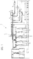
- Figure 1 shows the planimetric development (so-called layout) of a plant for automatically packaging articles such as, for example, food products, in particular confectionery products as a general plan view.
- the articles in question consist of products such as snacks, bars of chocolate, biscuits or stacks of biscuits in respective packages in the form of flexible wrappers (for example, of the type currently known as "flow-pack") and arranged in groups in respective containers such as parallelepipedal cardboard boxes. These boxes are filled in respective "source stations” M provided, in the embodiment illustrated, in groups of ten.
- the structure of the source stations M (usually consisting, in cascade, of a first wrapping machine of the flow-pack type followed by a boxing machine proper) is widely known in the art and, as such, need not be described in detail here, since it is also irrelevant with respect to an understanding of the invention.
- the source stations M supply the respective packaged articles onto an output line L typically consisting of an assembly of conveyors (for example, chain or belt conveyors) which define a respective flow line of articles for each station M.
- an output line L typically consisting of an assembly of conveyors (for example, chain or belt conveyors) which define a respective flow line of articles for each station M.
- the output end of the line L (shown in particular on the lefthand side of Figure 2) can be viewed as a conveyor such as, for example, a motor-driven belt conveyor on which the articles A are in their respective advancing lines indicated L1 to L10.
- the operation of the device according to the invention is usually such that it allows the articles A to be fed in a flow, which is as regular as possible, therefore timed exactly and without interruptions in continuity, towards respective handling stations situated downstream, generally indicated G.
- the stations G can consist of wrapping machines for wrapping each article A (and thus each box) in a respective flexible wrapper (flow-pack).
- both the choice of the number of stations G relative to the number of stations M and the adoption of an operating arrangement with master stations and auxiliary stations and the relative positioning of these stations should be considered as factors which generally have no influence on the structure of the device 1, in the sense that the device 1 can be arranged such that it serves any number of upstream stations M and downstream stations G, independently of the operating strategy adopted for the latter and as regards the spatial arrangement thereof.
- the device 1 is arranged such that it receives the articles A which arrive at the output end of the line L arranged end-to-end, that is, in such a way that the articles A, on the device 1, tend initially to follow an advancing path aligned with the advancing paths of the lines L1, ..., L10.
- the same device 1 should then transfer the articles A to the lines G located downstream by a movement (initially of adjustment and then of net translation) which develops in a direction generally transverse the advancing directions on the line L and entry into the device 1.
- the device 1 substantially consists of a plate 2 usually consisting of a metal plate mounted in a fixed position on a casing 3 and extending, in normal operating conditions, in a generally horizontal direction.
- a conveyor device consisting, in a preferred embodiment, of two lateral motor-driven members 3 located along the longer sides of the plate 2, acts above the plate 2.
- each of the members 3 consists of a chain (or a similar flexible element) which is wound - in known manner - about respective end rollers (not shown in the drawing, but located at the upstream and downstream ends of the plate 2 respectively) with an active pass 3a extending horizontally above the plate 2 and a return pass located above or below the plate 2.
- Rectilinear entrainment elements 5 consisting, for example, of sheets or strips 5 extend between the two chains 3 in a direction generally transverse the arrival direction of the articles A on the device 1.
- the strips 5 are supported at their ends by the active passes 3a of the chains 3 and generally extend downwards (towards the plate 2 but usually without touching it) in a position of interference with the articles A which are on the plate itself.
- the articles A situated on the plate itself are subjected to a thrust movement (brushing) causing the articles A, which arrive on the plate 2 scattered (that is, in a flow which is quite irregular relative to the advancing direction on the line L), to give rise to an ordered sequence of rows of articles A which advance on the plate 2.
- the term "row” is intended to define a line of articles A aligned in a direction transverse the direction of advance on the line L with the rear side of the articles bearing on a respective motor-driven strip 5 which advances the articles A onto the plate 2 (continuously or, better, in steps).
- the rows are generally incomplete: see in this respect the end of the device 1 which is further to the left in Figure 2.
- the advance of the articles A along the paths L1, ..., L10 is not totally free of spaces or breaks in continuity.
- the presence of a space or a break in continuity on any of the paths L1,..., L10 is manifested by a corresponding space in the row of articles A which is to be formed on the device 2.
- the articles A are preferably transferred on the device 1 (and, in particular, on the plate 2) when they have been subjected to a first action in which they are at least partially arranged in rows.
- an ordering element such as a further strip or barrier 6 with associated drive means (not illustrated but of a widely known type) which support the barrier 6 such that it is periodically lowered from above towards the outlet end of the line L such that a given number of articles arriving on the line L accumulate against it, arranging these articles in order - at least approximately - in a line intended to form a respective row of articles being transferred on the device 1.
- the device 1 intervenes in order to render the row compact, that is, it moves the articles A in each row towards one another which leads to the elimination of any existing spaces (for example, if there is a lack of articles in the flow on one or more of the supply paths L1,..., L10) between adjacent articles.
- a stopping structure 7 is provided consisting, for example, of a side made of sheet metal which extends along the corresponding longitudinal edge of the plate 2 in a position such that it interferes with the plate 2 itself, preferably with a lower edge part 4a, turned under the plane of the plate 2, and extending at approximately the same height as the plate 2 itself.
- a transverse movable element emerges, through a respective window, which, in the example illustrated, consists of a further belt conveyor 8 having an upper pass 8a which acts horizontally and is aligned exactly with the plane of the plate 2 and a lower pass 8b situated below the plane of the plate 2 itself.
- the belt 8 is wound (according to a widely known solution) on end pulleys or rollers 9 with associated drive elements 9a (of a widely known type). When they are actuated, the rollers or pulleys 9 move the belt 8 itself such that the upper pass 8a follows a net translation path in the direction transverse the direction of advance of the rows of articles A controlled by the strips 5.
- the net effect of the advance of the upper pass 8a is to carry the articles A, combined in a row but spaced apart from each other (even irregularly if there are spaces because of shortages in the supply on the respective conveying line L1, ..., L10), to move gradually against the side plate 7 so as to form a compact row, that is to say, an array in which all the articles A are adjacent one another, without spaces, forming a line which bears at one end against the side plate 7: it will be appreciated that the above occurs whilst the articles A continue their longitudinal sliding movement on the plate 2 under the action of the strips 5.
- this advance movement (and hence the actuation movement of the strips 5, controlled by the chains 3 in the example illustrated) can occur continuously or in steps, according to the solution preferred at the time.
- the gradual compacting movement of the row by virtue of the resistance from the side plate 7 can be performed very gradually and smoothly, that is, by the effect of a translation movement of the upper pass 8a of the motor-driven belt 8 at reduced speed, if there is an initial acceleration ramp and a corresponding final deceleration ramp which avoids great stresses which could damage the articles A being applied thereto.
- the articles A By virtue of the gradual advance along the plate 2 controlled by the strips 5, the articles A, now arranged in compact rows, travel beyond the position in which the belt 8 acts and pass to one (or more) withdrawal station (s) arranged in cascade.
- Figure 2 shows the structure of one of these withdrawal stations, that is to say, in the example illustrated, the station which is in the most upstream position relative to the device 2: this is the withdrawal station intended to supply the processing station G located further upstream, in the direction of flow of the articles A within the scope of the plant according to Figure 1.
- the withdrawal station generally indicated 10, has a structure which, to a certain degree, is similar to the structure adopted for performing the lateral compacting action of the rows by the belt 8.
- the sliding surface defined by the plate 2 has a rectangular window in which the further motor-driven belt conveyor 11 extends horizontally, this belt conveyor having an upper pass 11a, aligned exactly with the plane of the plate 2, and a lower, return pass 11b located below the plate 2 itself, with end rollers 12 which control the advance movement of the upper pass 11a of the conveyor in the direction which discharges the articles A from the device 1.
- the side plate 7 has an aperture (indicated 7a in Figure 1) in correspondence with the withdrawal station 10.
- a further difference with respect to the assembly arrangement of the conveyor-compacting device 8 is provided by the fact that the withdrawal conveyor 11 does not extend over the entire transverse dimension of the plate 2 but, on the contrary, only over a portion or recess corresponding to the width (measured in the direction transverse the direction of advance imparted by the strips 5) of a given number of articles A (for example, with reference to the example illustrated, three articles A).
- the movement of the conveyor 11 is such that three (or, in general, n ) articles A are withdrawn by the device 1 so as to be sent on an outlet conveyor C constituting the feed conveyor of a respective actuating station G.
- the conveyor C is also formed by a motor-driven-type endless belt having a loading or upstream end C situated in the immediate vicinity of the outlet end, indicated 11c, of the conveyor 11.
- each of the withdrawal stations 10 to tap a predetermined given number (3, in the example illustrated here) of articles A from the rows A advancing on the plate 2, transversely to the direction of advance of the rows.
- the withdrawal action thus performed determines the removal, so to speak, of an end or head part within the scope of the row of articles A.
- the rows of articles A advance towards a further lateral translation device consisting of a belt 8 arranged in a manner substantially similar to that described above and the operation of which is to bring the remainder of the line back into contact with the side plate 7 so as to return a given number of articles A into the vicinity of the side plate 7 itself.
- the solution described has the advantage of being able to minimise (possibly reducing it to one unit) the number of articles A which are tapped from time to time from the device 1 in order to advance towards a respective processing station G.
- This enables a precise regulation or regularisation of the flow of articles towards the processing stations G to be achieved, which, in turn, enables the presence of accumulation zones (storage) in the feed lines of these machines to be reduced and virtually eliminated.
Landscapes
- Mechanical Engineering (AREA)
- Engineering & Computer Science (AREA)
- Attitude Control For Articles On Conveyors (AREA)
- Packaging Of Special Articles (AREA)
- Container Filling Or Packaging Operations (AREA)
- Waveguide Switches, Polarizers, And Phase Shifters (AREA)
- Supplying Of Containers To The Packaging Station (AREA)
- Paper (AREA)
- Manufacture Of Iron (AREA)
- Filtering Of Dispersed Particles In Gases (AREA)
- Auxiliary Devices For And Details Of Packaging Control (AREA)
- Seeds, Soups, And Other Foods (AREA)
- Confectionery (AREA)
Abstract
A preferred application in automatic packaging machines for food products, such as confectionery products.
Description
- The present invention relates to a process for conveying articles supplied in respective flow lines adjacent to one another.
- The invention has been developed with particular attention to the possible use in the field of plants for automatically packaging products, such as food products, for example confectionery products.
- Within the context of this application, the problem of sorting the flow of articles coming from respective source stations to subsequent processing stations located downstream in the direction of flow of the articles occurs relatively frequently. For example, the source stations can be packaging machines in which products such as snacks, biscuits, etc., packaged in flexible wrappers (flow-packs), are inserted in groups in respective boxes. The further processing stations can, for example, be wrapping machines in which each box is in turn inserted in a further wrapping in the form of a flexible wrapper of the flow-pack type.
- Within the context of this application, a number of problems arise of which account must be taken.
- Firstly, the source stations (for example, the boxing machines) usually supply a conveying line with parallel rows. Each source machine supplies a respective row with a flow of articles which, although it is substantially constant, is not completely continuous, owing to the various reasons: for example, temporary stoppages of the source station because of a lack of packaging material, discharge of defective articles upstream or downstream of the source station, etc..
- Secondly, the number of source stations and thus of the parallel rows of the flow of articles generated thereby is generally different from the number of processing stations provided downstream. For example, it is possible to envisage ten source stations (for example, ten boxing machines) downstream of which there are only two wrapping machines, or four wrapping machines of which two are intended to operate continuously whilst the other two are used to take account of possible interruptions in the operation of the other wrapping machines or of incidents occurring in the flow of articles to be packaged.
- It is generally known to overcome the above problems by resorting to a so-called accumulation (or "store") function, that is, by providing for a certain amassing of articles (the so-called accumulation or store) between the outlets of the source stations and the inlets of the stations situated downstream, from which the articles themselves can be taken up in an ordered flow so as to be sent in a regular rhythm to the handling stations located downstream.
- Although this situation is entirely satisfactory in theory, it conflicts with certain practical difficulties.
- Firstly, forming an accumulation or store of articles generally requires the stoppage or at least a great deceleration of the movement of the advancing articles themselves. In modern packaging plants with high processing rates of the articles (some hundreds of units per minute), the speed of the advancing articles tends to be fairly high: any stoppage or great deceleration, above all when it occurs as a result of impact on the articles located downstream, may be particularly damaging, especially with fragile articles, with soft and yielding articles and/or with articles which, particularly when packaged, display marked resilience to knocks: in practice, one or more articles may well be bounced out of their box because of the effect of knocking against a stop barrier. Again, particularly when products which are not yet wrapped are used, the knocks can give rise to fragments or small pieces which can soil the packaging plant.
- Secondly, the greater the linear speed of movement of the articles, the greater the space occupied by the accumulation or storage areas.
- The object of the present invention is to provide a process which can overcome the above problems, on the one hand, avoiding great stresses on the articles processed and, on the other hand, minimising the need for recourse to an accumulation zone, thus reducing the space occupied by the packaging plant.
- According to the present invention this object is achieved by virtue of a process having the characteristics given specifically in
Claim 1. A further object of the invention is a device for performing the above process. - The invention will now be described, purely by way of non-limiting example, with reference to the appended drawings, in which:
- Figure 1 shows the development in plan view of an automatic packaging plant comprising a device according to the invention,
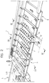
- Figure 2 shows the structure of a device according to the invention in a schematic view in perspective,
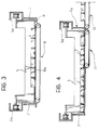
- Figure 3 is a section along the line III-III of Figure 2, and
- Figure 4 is a section along the line IV-IV of Figure 2.
- Figure 1 shows the planimetric development (so-called layout) of a plant for automatically packaging articles such as, for example, food products, in particular confectionery products as a general plan view.
- In order to fix the concept, it can be imagined that the articles in question consist of products such as snacks, bars of chocolate, biscuits or stacks of biscuits in respective packages in the form of flexible wrappers (for example, of the type currently known as "flow-pack") and arranged in groups in respective containers such as parallelepipedal cardboard boxes. These boxes are filled in respective "source stations" M provided, in the embodiment illustrated, in groups of ten.
- The structure of the source stations M (usually consisting, in cascade, of a first wrapping machine of the flow-pack type followed by a boxing machine proper) is widely known in the art and, as such, need not be described in detail here, since it is also irrelevant with respect to an understanding of the invention.
- For this purpose, it is sufficient to note that the source stations M supply the respective packaged articles onto an output line L typically consisting of an assembly of conveyors (for example, chain or belt conveyors) which define a respective flow line of articles for each station M.
- In practice, the output end of the line L (shown in particular on the lefthand side of Figure 2) can be viewed as a conveyor such as, for example, a motor-driven belt conveyor on which the articles A are in their respective advancing lines indicated L1 to L10.
- As regards the inflow conditions of the articles A at the downstream end of the line L, it can be noted that:
- as stated above, the articles A arrive on paths which are parallel to one another, each path corresponding to the flow of articles generated by a respective source station M;
- each flow, although it is uniform overall, is not uniform in the absolute sense, in the sense that breaks in continuity may be present because of various factors, such as the temporary stoppage of the respective source station M (for changing paper, discharging defective articles, etc.); and
- the articles A which arrive on the various lines L1, L10 are not generally synchronised with one another in the sense that the position of the articles in the various flows is not such that these articles are generally aligned relative to each another transverse the line L.
- The operation of the device according to the invention, generally indicated 1, is usually such that it allows the articles A to be fed in a flow, which is as regular as possible, therefore timed exactly and without interruptions in continuity, towards respective handling stations situated downstream, generally indicated G.
- For example, the stations G can consist of wrapping machines for wrapping each article A (and thus each box) in a respective flexible wrapper (flow-pack).
- In the embodiment illustrated, there are four downstream handling stations G of which the first two, those situated further to the left in Figure 1, can be used as master stations, intended to operate continuously, whilst the other two, those illustrated further to the right, can function as auxiliary packing stations, intended to function intermittently both to replace a principal station which is temporarily stopped and to compensate for accumulations of articles, because of particular interference with the regular operation of the plant.
- In each case, both the choice of the number of stations G relative to the number of stations M and the adoption of an operating arrangement with master stations and auxiliary stations and the relative positioning of these stations should be considered as factors which generally have no influence on the structure of the
device 1, in the sense that thedevice 1 can be arranged such that it serves any number of upstream stations M and downstream stations G, independently of the operating strategy adopted for the latter and as regards the spatial arrangement thereof. - In the remainder of the present description, specific reference will be made to the method by which the
device 1 regulates the supply of the articles A to one of the stations G located downstream. It should be appreciated that it is intended that identical methods are adopted for the supply to the other stations G. - In the embodiment illustrated, the
device 1 is arranged such that it receives the articles A which arrive at the output end of the line L arranged end-to-end, that is, in such a way that the articles A, on thedevice 1, tend initially to follow an advancing path aligned with the advancing paths of the lines L1, ..., L10. Thesame device 1 should then transfer the articles A to the lines G located downstream by a movement (initially of adjustment and then of net translation) which develops in a direction generally transverse the advancing directions on the line L and entry into thedevice 1. - The
device 1 substantially consists of aplate 2 usually consisting of a metal plate mounted in a fixed position on acasing 3 and extending, in normal operating conditions, in a generally horizontal direction. - A conveyor device consisting, in a preferred embodiment, of two lateral motor-driven
members 3 located along the longer sides of theplate 2, acts above theplate 2. In particular, each of themembers 3 consists of a chain (or a similar flexible element) which is wound - in known manner - about respective end rollers (not shown in the drawing, but located at the upstream and downstream ends of theplate 2 respectively) with anactive pass 3a extending horizontally above theplate 2 and a return pass located above or below theplate 2. -
Rectilinear entrainment elements 5 consisting, for example, of sheets orstrips 5 extend between the twochains 3 in a direction generally transverse the arrival direction of the articles A on thedevice 1. Thestrips 5 are supported at their ends by theactive passes 3a of thechains 3 and generally extend downwards (towards theplate 2 but usually without touching it) in a position of interference with the articles A which are on the plate itself. - The arrangement described is such that, when the
chains 3 move (as a result of the end rollers being rotated - also in known manner - by motors not illustrated), theupper passes 3a and thestrips 5 suspended therebetween perform a net translational movement along and above the upper face of the plate 2: with reference to the position illustrated in Figures 1 and 2, this movement is from left to right. - By virtue of the reduced distance between the lower edge of the
strips 5 and theplate 2, the articles A situated on the plate itself are subjected to a thrust movement (brushing) causing the articles A, which arrive on theplate 2 scattered (that is, in a flow which is quite irregular relative to the advancing direction on the line L), to give rise to an ordered sequence of rows of articles A which advance on theplate 2. The term "row" is intended to define a line of articles A aligned in a direction transverse the direction of advance on the line L with the rear side of the articles bearing on a respective motor-drivenstrip 5 which advances the articles A onto the plate 2 (continuously or, better, in steps). - Since they are only just formed when the articles A enter the
device 1, the rows are generally incomplete: see in this respect the end of thedevice 1 which is further to the left in Figure 2. As explained above, although it is substantially continuous, the advance of the articles A along the paths L1, ..., L10, is not totally free of spaces or breaks in continuity. The presence of a space or a break in continuity on any of the paths L1,..., L10 is manifested by a corresponding space in the row of articles A which is to be formed on thedevice 2. - It will be appreciated that the solution for the formation of the rows described above is given purely by way of example. In particular, instead of using
strips 5 held at the ends by thechains 3a, located on opposite sides of theplate 2, it is possible to envisage a different type of entrainment structure. For example, it is possible to envisage usingstrips 5 which, instead of being supported at both ends, are supported by a drive structure located on one side of theplate 2 and are thus mounted such that they project relative to theplate 2. Or, still for causing the sliding movement of the articles A on theplate 2 by acting from above, it is possible to envisage using structures with motor-driven strips or equivalent elements, (for example, blades, etc.). In any case, the choice of one or other solution should not be used to limit the implementation of the invention. - In each case, the articles A are preferably transferred on the device 1 (and, in particular, on the plate 2) when they have been subjected to a first action in which they are at least partially arranged in rows.
- For this purpose, it is possible to dispose at the outlet end of the
line 2 an ordering element, such as a further strip or barrier 6 with associated drive means (not illustrated but of a widely known type) which support the barrier 6 such that it is periodically lowered from above towards the outlet end of the line L such that a given number of articles arriving on the line L accumulate against it, arranging these articles in order - at least approximately - in a line intended to form a respective row of articles being transferred on thedevice 1. - As an alternative to a barrier, a solution which may not be considered the best as regards the impact of the articles A, it is possible to envisage attaining the same function with a different element or surface which can decelerate the movement of the articles (A), for example, with a further motor-driven belt, interposed between the line L and the inlet end of the device 1: the belt being advanced in steps which gives rise to the formation of a line of articles intended to constitute a row whenever the movement of the belt is stopped.
- In each case, when a row of articles A has formed on the
plate 2, thedevice 1 intervenes in order to render the row compact, that is, it moves the articles A in each row towards one another which leads to the elimination of any existing spaces (for example, if there is a lack of articles in the flow on one or more of the supply paths L1,..., L10) between adjacent articles. - For this purpose (see the view in Figure 3 in particular), on one of the sides of the plate 2 (and, to be precise, on the side from which the articles will subsequently be supplied to the handling stations G) a
stopping structure 7 is provided consisting, for example, of a side made of sheet metal which extends along the corresponding longitudinal edge of theplate 2 in a position such that it interferes with theplate 2 itself, preferably with a lower edge part 4a, turned under the plane of theplate 2, and extending at approximately the same height as theplate 2 itself. - In correspondence with the
side plate 7, in the plane of theplate 2, a transverse movable element emerges, through a respective window, which, in the example illustrated, consists of afurther belt conveyor 8 having anupper pass 8a which acts horizontally and is aligned exactly with the plane of theplate 2 and a lower pass 8b situated below the plane of theplate 2 itself. Thebelt 8 is wound (according to a widely known solution) on end pulleys or rollers 9 with associated drive elements 9a (of a widely known type). When they are actuated, the rollers or pulleys 9 move thebelt 8 itself such that theupper pass 8a follows a net translation path in the direction transverse the direction of advance of the rows of articles A controlled by thestrips 5. - The net effect of the advance of the
upper pass 8a (from top to bottom with reference to Figure 2 and from left to right with reference to Figure 3) is to carry the articles A, combined in a row but spaced apart from each other (even irregularly if there are spaces because of shortages in the supply on the respective conveying line L1, ..., L10), to move gradually against theside plate 7 so as to form a compact row, that is to say, an array in which all the articles A are adjacent one another, without spaces, forming a line which bears at one end against the side plate 7: it will be appreciated that the above occurs whilst the articles A continue their longitudinal sliding movement on theplate 2 under the action of thestrips 5. - As stated above, this advance movement (and hence the actuation movement of the
strips 5, controlled by thechains 3 in the example illustrated) can occur continuously or in steps, according to the solution preferred at the time. - The gradual compacting movement of the row by virtue of the resistance from the
side plate 7 can be performed very gradually and smoothly, that is, by the effect of a translation movement of theupper pass 8a of the motor-drivenbelt 8 at reduced speed, if there is an initial acceleration ramp and a corresponding final deceleration ramp which avoids great stresses which could damage the articles A being applied thereto. - By virtue of the gradual advance along the
plate 2 controlled by thestrips 5, the articles A, now arranged in compact rows, travel beyond the position in which thebelt 8 acts and pass to one (or more) withdrawal station (s) arranged in cascade. - Figure 2 (and, similarly, Figure 4) shows the structure of one of these withdrawal stations, that is to say, in the example illustrated, the station which is in the most upstream position relative to the device 2: this is the withdrawal station intended to supply the processing station G located further upstream, in the direction of flow of the articles A within the scope of the plant according to Figure 1.
- The withdrawal station, generally indicated 10, has a structure which, to a certain degree, is similar to the structure adopted for performing the lateral compacting action of the rows by the
belt 8. - In this case too, in fact, the sliding surface defined by the
plate 2 has a rectangular window in which the further motor-drivenbelt conveyor 11 extends horizontally, this belt conveyor having an upper pass 11a, aligned exactly with the plane of theplate 2, and a lower, return pass 11b located below theplate 2 itself, withend rollers 12 which control the advance movement of the upper pass 11a of the conveyor in the direction which discharges the articles A from thedevice 1. - In order to achieve this result, the
side plate 7 has an aperture (indicated 7a in Figure 1) in correspondence with the withdrawal station 10. - A further difference with respect to the assembly arrangement of the conveyor-compacting
device 8 is provided by the fact that thewithdrawal conveyor 11 does not extend over the entire transverse dimension of theplate 2 but, on the contrary, only over a portion or recess corresponding to the width (measured in the direction transverse the direction of advance imparted by the strips 5) of a given number of articles A (for example, with reference to the example illustrated, three articles A). - This, therefore, means that only the first three articles (or, in general, the first n articles) which are sliding close to the
side plate 7 are affected by the tapping action actuated by the upper pass 11a of theconveyor 11. - In particular, the movement of the
conveyor 11 is such that three (or, in general, n) articles A are withdrawn by thedevice 1 so as to be sent on an outlet conveyor C constituting the feed conveyor of a respective actuating station G. - Preferably, the conveyor C is also formed by a motor-driven-type endless belt having a loading or upstream end C situated in the immediate vicinity of the outlet end, indicated 11c, of the
conveyor 11. - The arrangement described thus allows each of the withdrawal stations 10 to tap a predetermined given number (3, in the example illustrated here) of articles A from the rows A advancing on the
plate 2, transversely to the direction of advance of the rows. - The withdrawal action thus performed determines the removal, so to speak, of an end or head part within the scope of the row of articles A.
- In order to enable other withdrawal actions to be performed, once the withdrawal station 10 has been passed, the rows of articles A advance towards a further lateral translation device consisting of a
belt 8 arranged in a manner substantially similar to that described above and the operation of which is to bring the remainder of the line back into contact with theside plate 7 so as to return a given number of articles A into the vicinity of theside plate 7 itself. - When the row has been placed against the
side plate 7, a further group of articles (for example, three other articles) can be taken up in the lateral direction relative to the device 1: the whole being in accordance with criteria which are entirely identical to those described above in relation to the withdrawal station 10. - The solution described has the advantage of being able to minimise (possibly reducing it to one unit) the number of articles A which are tapped from time to time from the
device 1 in order to advance towards a respective processing station G. This enables a precise regulation or regularisation of the flow of articles towards the processing stations G to be achieved, which, in turn, enables the presence of accumulation zones (storage) in the feed lines of these machines to be reduced and virtually eliminated. - What has been stated above applies also as regards the possibility of regularising and rendering uniform the withdrawal action of the articles A from the
device 1, which enables the feed lines of the stations G to be constantly and regularly supplied, in almost certain conditions, minimising the need to recourse to the operation of the stations G which are kept on standby (auxiliary stations G).
Claims (12)
- A process for conveying articles (A) supplied in respective flow lines (L1, ..., L10) adjacent one another, characterised in that it comprises the operations of:- forming respective rows of articles from the articles (A) advancing along the flow lines (L1, ..., L10), each row consisting of articles (A) aligned in a direction transverse the flow lines (L1, ..., L10),- moving the articles (A) in each row towards one another so as to form compact rows consisting of articles (A) in contact with each other, and- withdrawing (10) a predetermined number (n) of articles (A) from each compact row; this withdrawal being effected by virtue of a translation of the predetermined number (n) of articles in a direction transverse the direction of advance of the rows.
- A process according to Claim 1, characterised in that the rows of articles (A) are formed by supplying the articles (A) onto a sliding surface (2), thus providing movable alignment means (5) which act on the articles (A) and cause them to slide on the sliding surface (2) so as to bring the articles (A) into alignment in a row consisting of articles (A) in contact with the alignment means (5).
- A process according to Claim 1 or Claim 2, characterised in that the rows are formed by acting, at least temporarily, on the articles (A) with means (6) for decelerating the movement.
- A process according to any one of Claims 1 to 3, characterised in that the moving together of the articles (A) in each row is effected by an abutment surface (7) which is substantially adjacent and aligned with the direction of advance of the rows and thus favours a sliding movement of the articles (A) towards the abutment surface (7).
- A process according to Claim 4, characterised in that it comprises the operation of providing an aperture (7a) in the abutment surface (7) for the passage of the articles (A) withdrawn in correspondence with the position in which the predetermined number of articles (A) are taken up.
- A process according to any one of the preceding claims, characterised in that it comprises the operation of withdrawing articles (A) in a plurality of positions of the general advancing movement of the rows, between the successive withdrawal positions, a further operation for the accumulation of these rows being provided.
- A device for conveying articles (A) supplied in respective adjacent flow lines (L1, ..., L10), characterised in that it comprises:- alignment means (5) for forming respective rows of articles from the articles (A) advancing along the flow lines (L1, ..., L10), each row consisting of articles (A) aligned in a transverse direction relative to the flow lines (L1, ...L10),- conveyor means (8) for moving the articles (A) in each row towards one another so as to form compact rows formed by articles (A) in contact with each another, and- further conveyor means (11) for withdrawing (10) a predetermined number (n) of articles (A) from each compact row; the further conveyor means being arranged so as to effect a translation of the predetermined number (n) of articles in a transverse direction relative to the direction of advance of the rows.
- A device according to Claim 7, characterised in that it comprises a sliding surface (2) onto which the articles (A) are supplied from the flow lines (L1, ..., L10) as well as motor-driven (3) alignment means (5) which produce the sliding movement of the articles (A) on the sliding surface (2) so as to bring the articles (A) into alignment in a row consisting of articles in contact with the alignment means (5).
- A device according to Claim 7 or Claim 8, characterised in that it comprises means (6) for decelerating the movement with which means the articles (A) cooperate, at least temporarily, in order to form the rows.
- A device according to any one of Claims 7 to 9, characterised in that it comprises an abutment surface (7) which is substantially adjacent and aligned with the direction of advance of the rows and conveyor means (8) for producing a sliding movement of the articles (A) towards the abutment surface (7).
- A device according to Claim 10, characterised in that the abutment surface (7) has an aperture (7a) for the passage of the articles withdrawn in correspondence with the further conveyor means.
- A device according to any one of Claims 7 to 11, characterised in that it comprises a plurality of further conveyor means (11), respective conveyor means (8) being interposed between the further conveyor means (11) of the plurality for accumulating the rows between two successive withdrawal operations of articles (A).
Applications Claiming Priority (2)
| Application Number | Priority Date | Filing Date | Title |
|---|---|---|---|
| CH750/93 | 1993-03-12 | ||
| CH00750/93A CH688823A5 (en) | 1993-03-12 | 1993-03-12 | Method and device for conveying articles, particularly for automatic packaging installations. |
Publications (3)
| Publication Number | Publication Date |
|---|---|
| EP0614833A2 true EP0614833A2 (en) | 1994-09-14 |
| EP0614833A3 EP0614833A3 (en) | 1995-01-18 |
| EP0614833B1 EP0614833B1 (en) | 1997-06-04 |
Family
ID=4194332
Family Applications (1)
| Application Number | Title | Priority Date | Filing Date |
|---|---|---|---|
| EP94102692A Expired - Lifetime EP0614833B1 (en) | 1993-03-12 | 1994-02-23 | A process and a device for conveying articles, particularly for automatic packaging plants |
Country Status (22)
| Country | Link |
|---|---|
| US (1) | US5396980A (en) |
| EP (1) | EP0614833B1 (en) |
| AT (1) | ATE153975T1 (en) |
| BG (1) | BG61759B1 (en) |
| CH (1) | CH688823A5 (en) |
| CZ (1) | CZ52994A3 (en) |
| DE (1) | DE69403514T2 (en) |
| DK (1) | DK0614833T3 (en) |
| EE (1) | EE03153B1 (en) |
| ES (1) | ES2104203T3 (en) |
| GR (1) | GR3024172T3 (en) |
| HR (1) | HRP940169B1 (en) |
| HU (1) | HU216391B (en) |
| LT (1) | LT3212B (en) |
| LV (1) | LV11162B (en) |
| PL (1) | PL172867B1 (en) |
| RO (1) | RO117611B1 (en) |
| RU (1) | RU2125011C1 (en) |
| SG (1) | SG43988A1 (en) |
| SI (1) | SI9400125A (en) |
| SK (1) | SK279527B6 (en) |
| YU (1) | YU48616B (en) |
Cited By (1)
| Publication number | Priority date | Publication date | Assignee | Title |
|---|---|---|---|---|
| CN103950579A (en) * | 2014-04-29 | 2014-07-30 | 佘峰 | Guide device of crawler belt packaging machine |
Families Citing this family (9)
| Publication number | Priority date | Publication date | Assignee | Title |
|---|---|---|---|---|
| US6189300B1 (en) * | 1999-08-02 | 2001-02-20 | Tuan Vinh Le | Wrapping machine |
| JP2001225029A (en) * | 2000-02-18 | 2001-08-21 | Hiroshi Maeda | Transfer device for online inspecting internal quality |
| US7017730B2 (en) * | 2000-05-12 | 2006-03-28 | Lockheed Martin Corporation | Bi-directional mail tray pusher |
| US7048622B2 (en) * | 2002-02-04 | 2006-05-23 | Conagra Foods, Inc. | Automated laterally offset retractable food dislodgement or guiding mechanisms and associated methods and systems |
| ITTO20070766A1 (en) * | 2007-10-26 | 2009-04-27 | Soremartec Sa | "DEVICE TO REDUCE THE MISALIGNMENT BETWEEN CONVEYED PRODUCTS AND ITS PROCEDURE" |
| US7726461B2 (en) * | 2008-08-12 | 2010-06-01 | Laitram, L.L.C. | Apparatuses and methods for controlling the spacing of and ejecting conveyed objects |
| WO2019025904A1 (en) * | 2017-07-31 | 2019-02-07 | Dematic Corp. | Article sorter with active discharge |
| FI130923B1 (en) * | 2018-05-04 | 2024-05-29 | Actiw Oy | Grouping station for grouping pallets |
| IT202000023044A1 (en) * | 2020-09-30 | 2022-03-30 | Azionaria Costruzioni Acma Spa | METHOD AND DEVICE FOR FEEDING ITEMS |
Citations (6)
| Publication number | Priority date | Publication date | Assignee | Title |
|---|---|---|---|---|
| US2804961A (en) * | 1954-03-16 | 1957-09-03 | Meyer Geo J Mfg Co | Conveyor apparatus for articleprocessing units |
| US2833393A (en) * | 1956-09-25 | 1958-05-06 | Lamb Co F Jos | Distributing conveyor arrangements |
| DE1943085A1 (en) * | 1968-08-29 | 1970-03-05 | Azionaria Costruzioni | Device for deriving products from a dispensing machine to the receiving machine |
| DE1786191A1 (en) * | 1968-01-04 | 1972-01-20 | Theegarten Franz | Packaging system e.g. for chocolate-coated sweets or other pieces of confectionery |
| DE2161618A1 (en) * | 1971-12-11 | 1973-06-14 | Haensel Otto Gmbh | METHOD AND DEVICE FOR FILLING SEVERAL WORK STATIONS WITH PIECES OF SUEDE, CONNECTED TO A COMMON FEEDER |
| EP0335639A1 (en) * | 1988-03-30 | 1989-10-04 | Burton's Gold Medal Biscuits Limited | Improvements in and relating to apparatus for automatically reorganising product lines |
Family Cites Families (10)
| Publication number | Priority date | Publication date | Assignee | Title |
|---|---|---|---|---|
| DE1291282C2 (en) * | 1964-02-19 | 1975-02-06 | DEVICE FOR TRANSFERRING CHOCOLATE BARS OR BARS | |
| US3429416A (en) * | 1967-07-18 | 1969-02-25 | Package Machinery Co | Transfer conveyor apparatus for candy bars and the like |
| US3463291A (en) * | 1967-10-20 | 1969-08-26 | Nat Biscuit Co | Article aligning and row accumulating apparatus |
| US3513629A (en) | 1967-12-08 | 1970-05-26 | Nat Biscuit Co | Overwrap packing machines |
| US3669240A (en) * | 1971-02-18 | 1972-06-13 | Del Monte Corp | Method and apparatus for orienting articles |
| DD90511A1 (en) * | 1971-07-21 | 1972-06-05 | ||
| CH600999A5 (en) * | 1975-07-22 | 1978-06-30 | Werz Furnier Sperrholz | |
| US4197935A (en) | 1976-06-07 | 1980-04-15 | Fmc Corporation | Automatic feeding of spaced articles to a processing machine |
| US4192416A (en) * | 1977-04-01 | 1980-03-11 | NIKO Konserven-Maschinenfabrik Hinsbek GmbH & Co., KG | Device for transferring piece material, in particular pieces of fruit or vegetable |
| IT1253225B (en) * | 1991-10-24 | 1995-07-11 | Azionaria Costruzioni Acma Spa | COMPACTING UNIT OF GROUPS OF GROUND PRODUCTS |
-
1993
- 1993-03-12 CH CH00750/93A patent/CH688823A5/en not_active IP Right Cessation
-
1994
- 1994-02-23 AT AT94102692T patent/ATE153975T1/en active
- 1994-02-23 EP EP94102692A patent/EP0614833B1/en not_active Expired - Lifetime
- 1994-02-23 DK DK94102692.4T patent/DK0614833T3/en not_active Application Discontinuation
- 1994-02-23 SG SG1996008706A patent/SG43988A1/en unknown
- 1994-02-23 ES ES94102692T patent/ES2104203T3/en not_active Expired - Lifetime
- 1994-02-23 DE DE69403514T patent/DE69403514T2/en not_active Expired - Fee Related
- 1994-03-01 LT LTIP1887A patent/LT3212B/en not_active IP Right Cessation
- 1994-03-04 US US08/205,501 patent/US5396980A/en not_active Expired - Lifetime
- 1994-03-08 YU YU10194A patent/YU48616B/en unknown
- 1994-03-09 LV LVP-94-48A patent/LV11162B/en unknown
- 1994-03-09 CZ CZ94529A patent/CZ52994A3/en unknown
- 1994-03-09 HU HU9400702A patent/HU216391B/en not_active IP Right Cessation
- 1994-03-10 SK SK300-94A patent/SK279527B6/en unknown
- 1994-03-10 BG BG98648A patent/BG61759B1/en unknown
- 1994-03-10 PL PL94302544A patent/PL172867B1/en unknown
- 1994-03-11 HR HR00750/93-5A patent/HRP940169B1/en not_active IP Right Cessation
- 1994-03-11 SI SI9400125A patent/SI9400125A/en unknown
- 1994-03-11 RO RO94-00406A patent/RO117611B1/en unknown
- 1994-03-11 RU RU94007637A patent/RU2125011C1/en active
- 1994-05-23 EE EE9400018A patent/EE03153B1/en unknown
-
1997
- 1997-07-18 GR GR970401817T patent/GR3024172T3/en unknown
Patent Citations (6)
| Publication number | Priority date | Publication date | Assignee | Title |
|---|---|---|---|---|
| US2804961A (en) * | 1954-03-16 | 1957-09-03 | Meyer Geo J Mfg Co | Conveyor apparatus for articleprocessing units |
| US2833393A (en) * | 1956-09-25 | 1958-05-06 | Lamb Co F Jos | Distributing conveyor arrangements |
| DE1786191A1 (en) * | 1968-01-04 | 1972-01-20 | Theegarten Franz | Packaging system e.g. for chocolate-coated sweets or other pieces of confectionery |
| DE1943085A1 (en) * | 1968-08-29 | 1970-03-05 | Azionaria Costruzioni | Device for deriving products from a dispensing machine to the receiving machine |
| DE2161618A1 (en) * | 1971-12-11 | 1973-06-14 | Haensel Otto Gmbh | METHOD AND DEVICE FOR FILLING SEVERAL WORK STATIONS WITH PIECES OF SUEDE, CONNECTED TO A COMMON FEEDER |
| EP0335639A1 (en) * | 1988-03-30 | 1989-10-04 | Burton's Gold Medal Biscuits Limited | Improvements in and relating to apparatus for automatically reorganising product lines |
Cited By (1)
| Publication number | Priority date | Publication date | Assignee | Title |
|---|---|---|---|---|
| CN103950579A (en) * | 2014-04-29 | 2014-07-30 | 佘峰 | Guide device of crawler belt packaging machine |
Also Published As
| Publication number | Publication date |
|---|---|
| RO117611B1 (en) | 2002-05-30 |
| LT3212B (en) | 1995-04-25 |
| US5396980A (en) | 1995-03-14 |
| HRP940169B1 (en) | 1997-12-31 |
| SK30094A3 (en) | 1995-01-12 |
| EP0614833B1 (en) | 1997-06-04 |
| ES2104203T3 (en) | 1997-10-01 |
| LV11162B (en) | 1996-10-20 |
| PL172867B1 (en) | 1997-12-31 |
| YU10194A (en) | 1997-01-08 |
| LTIP1887A (en) | 1994-10-25 |
| RU2125011C1 (en) | 1999-01-20 |
| HU9400702D0 (en) | 1994-06-28 |
| HU216391B (en) | 1999-06-28 |
| LV11162A (en) | 1996-04-20 |
| BG61759B1 (en) | 1998-05-29 |
| SG43988A1 (en) | 1997-11-14 |
| DE69403514D1 (en) | 1997-07-10 |
| GR3024172T3 (en) | 1997-10-31 |
| SI9400125A (en) | 1994-09-30 |
| HRP940169A2 (en) | 1996-08-31 |
| CH688823A5 (en) | 1998-04-15 |
| HUT69876A (en) | 1995-09-28 |
| BG98648A (en) | 1995-06-30 |
| DE69403514T2 (en) | 1997-10-02 |
| CZ52994A3 (en) | 1995-02-15 |
| DK0614833T3 (en) | 1997-09-01 |
| EP0614833A3 (en) | 1995-01-18 |
| ATE153975T1 (en) | 1997-06-15 |
| YU48616B (en) | 1999-03-04 |
| SK279527B6 (en) | 1998-12-02 |
| EE03153B1 (en) | 1999-02-15 |
Similar Documents
| Publication | Publication Date | Title |
|---|---|---|
| EP0331210B1 (en) | Method and apparatus for introducing into containers foil packages filled with an amorphous product | |
| US5133446A (en) | Device for the formation and transfer of groups of commodities | |
| US8474598B2 (en) | Device and method for composing packages for a packaging machine | |
| JP2006321567A (en) | Continuously operating packaging device | |
| US4443995A (en) | Metering device and method | |
| EP0614833B1 (en) | A process and a device for conveying articles, particularly for automatic packaging plants | |
| EP0634322A1 (en) | Method of feeding groups of tobacco items, in particular cigarettes, to a continuously operating packaging machine | |
| ITMI930314A1 (en) | PROCESS AND DEVICE FOR THE PACKAGING OF OBJECTS IN A CONTINUOUSLY OPERATING PROCESS | |
| JP2763181B2 (en) | Manufacturing equipment for large unit products in the form of handles in the group of small packs of tissue paper | |
| JP2000515835A (en) | Method and apparatus for receiving and piling products supplied in a plurality of rows, and transporting the pile of the obtained products to a packaging line | |
| CA2163612A1 (en) | System for conveying filled bottles | |
| EP2731870B1 (en) | Plant for packaging products in strips, such as chewing gum, and corresponding packaging method | |
| JP4853052B2 (en) | Grouping device | |
| US5619843A (en) | Film wrap machine | |
| EP1992562B1 (en) | Unit for forming groups of products for packaging lines and related method | |
| CN211810371U (en) | Packaging device and transport device for film sections | |
| EP0317198A2 (en) | Packaging systems and packaging processes | |
| US2686543A (en) | Conveyer system | |
| JP2022527238A (en) | A system and operating method for wrapping paper rolls. | |
| EP0905065B1 (en) | Unit for forming and supplying stacks of products to a machine | |
| EP0077302B1 (en) | Method and machine for packaging several individually wrapped food products | |
| GB2053828A (en) | Selectively transferring packages between sets of conveyors | |
| JPH0516904A (en) | Encasing system and encasing and covering devices therefor |
Legal Events
| Date | Code | Title | Description |
|---|---|---|---|
| PUAI | Public reference made under article 153(3) epc to a published international application that has entered the european phase |
Free format text: ORIGINAL CODE: 0009012 |
|
| AK | Designated contracting states |
Kind code of ref document: A2 Designated state(s): AT BE CH DE DK ES FR GB GR IE IT LI LU MC NL PT SE |
|
| PUAL | Search report despatched |
Free format text: ORIGINAL CODE: 0009013 |
|
| AK | Designated contracting states |
Kind code of ref document: A3 Designated state(s): AT BE CH DE DK ES FR GB GR IE IT LI LU MC NL PT SE |
|
| RAP1 | Party data changed (applicant data changed or rights of an application transferred) |
Owner name: FERRERO OFFENE HANDELSGESELLSCHAFT M.B.H. Owner name: FERRERO S.P.A. Owner name: SOREMARTEC S.A. |
|
| 17P | Request for examination filed |
Effective date: 19950204 |
|
| 17Q | First examination report despatched |
Effective date: 19951208 |
|
| GRAG | Despatch of communication of intention to grant |
Free format text: ORIGINAL CODE: EPIDOS AGRA |
|
| GRAH | Despatch of communication of intention to grant a patent |
Free format text: ORIGINAL CODE: EPIDOS IGRA |
|
| GRAH | Despatch of communication of intention to grant a patent |
Free format text: ORIGINAL CODE: EPIDOS IGRA |
|
| GRAA | (expected) grant |
Free format text: ORIGINAL CODE: 0009210 |
|
| AK | Designated contracting states |
Kind code of ref document: B1 Designated state(s): AT BE CH DE DK ES FR GB GR IE IT LI LU MC NL PT SE |
|
| REF | Corresponds to: |
Ref document number: 153975 Country of ref document: AT Date of ref document: 19970615 Kind code of ref document: T |
|
| ITF | It: translation for a ep patent filed | ||
| REG | Reference to a national code |
Ref country code: CH Ref legal event code: NV Representative=s name: JACOBACCI & PERANI S.A. Ref country code: CH Ref legal event code: EP |
|
| REF | Corresponds to: |
Ref document number: 69403514 Country of ref document: DE Date of ref document: 19970710 |
|
| ET | Fr: translation filed | ||
| REG | Reference to a national code |
Ref country code: DK Ref legal event code: T3 |
|
| REG | Reference to a national code |
Ref country code: GR Ref legal event code: FG4A Free format text: 3024172 |
|
| REG | Reference to a national code |
Ref country code: ES Ref legal event code: FG2A Ref document number: 2104203 Country of ref document: ES Kind code of ref document: T3 |
|
| REG | Reference to a national code |
Ref country code: PT Ref legal event code: SC4A Free format text: AVAILABILITY OF NATIONAL TRANSLATION Effective date: 19970710 |
|
| PLBE | No opposition filed within time limit |
Free format text: ORIGINAL CODE: 0009261 |
|
| STAA | Information on the status of an ep patent application or granted ep patent |
Free format text: STATUS: NO OPPOSITION FILED WITHIN TIME LIMIT |
|
| 26N | No opposition filed | ||
| PGFP | Annual fee paid to national office [announced via postgrant information from national office to epo] |
Ref country code: MC Payment date: 20000118 Year of fee payment: 7 |
|
| PGFP | Annual fee paid to national office [announced via postgrant information from national office to epo] |
Ref country code: SE Payment date: 20010109 Year of fee payment: 8 |
|
| PGFP | Annual fee paid to national office [announced via postgrant information from national office to epo] |
Ref country code: AT Payment date: 20010110 Year of fee payment: 8 |
|
| PGFP | Annual fee paid to national office [announced via postgrant information from national office to epo] |
Ref country code: DK Payment date: 20010112 Year of fee payment: 8 |
|
| PGFP | Annual fee paid to national office [announced via postgrant information from national office to epo] |
Ref country code: IE Payment date: 20010118 Year of fee payment: 8 |
|
| PGFP | Annual fee paid to national office [announced via postgrant information from national office to epo] |
Ref country code: ES Payment date: 20010119 Year of fee payment: 8 |
|
| PGFP | Annual fee paid to national office [announced via postgrant information from national office to epo] |
Ref country code: CH Payment date: 20010122 Year of fee payment: 8 |
|
| PGFP | Annual fee paid to national office [announced via postgrant information from national office to epo] |
Ref country code: PT Payment date: 20010123 Year of fee payment: 8 |
|
| PGFP | Annual fee paid to national office [announced via postgrant information from national office to epo] |
Ref country code: NL Payment date: 20010129 Year of fee payment: 8 Ref country code: GR Payment date: 20010129 Year of fee payment: 8 |
|
| PGFP | Annual fee paid to national office [announced via postgrant information from national office to epo] |
Ref country code: LU Payment date: 20010205 Year of fee payment: 8 |
|
| PG25 | Lapsed in a contracting state [announced via postgrant information from national office to epo] |
Ref country code: MC Free format text: LAPSE BECAUSE OF NON-PAYMENT OF DUE FEES Effective date: 20010228 |
|
| REG | Reference to a national code |
Ref country code: GB Ref legal event code: IF02 |
|
| PG25 | Lapsed in a contracting state [announced via postgrant information from national office to epo] |
Ref country code: LU Free format text: LAPSE BECAUSE OF NON-PAYMENT OF DUE FEES Effective date: 20020223 Ref country code: AT Free format text: LAPSE BECAUSE OF NON-PAYMENT OF DUE FEES Effective date: 20020223 |
|
| PG25 | Lapsed in a contracting state [announced via postgrant information from national office to epo] |
Ref country code: SE Free format text: LAPSE BECAUSE OF NON-PAYMENT OF DUE FEES Effective date: 20020224 |
|
| PG25 | Lapsed in a contracting state [announced via postgrant information from national office to epo] |
Ref country code: IE Free format text: LAPSE BECAUSE OF NON-PAYMENT OF DUE FEES Effective date: 20020225 Ref country code: ES Free format text: LAPSE BECAUSE OF NON-PAYMENT OF DUE FEES Effective date: 20020225 |
|
| PG25 | Lapsed in a contracting state [announced via postgrant information from national office to epo] |
Ref country code: LI Free format text: LAPSE BECAUSE OF NON-PAYMENT OF DUE FEES Effective date: 20020228 Ref country code: DK Free format text: LAPSE BECAUSE OF NON-PAYMENT OF DUE FEES Effective date: 20020228 Ref country code: CH Free format text: LAPSE BECAUSE OF NON-PAYMENT OF DUE FEES Effective date: 20020228 |
|
| PG25 | Lapsed in a contracting state [announced via postgrant information from national office to epo] |
Ref country code: PT Free format text: LAPSE BECAUSE OF NON-PAYMENT OF DUE FEES Effective date: 20020831 |
|
| PG25 | Lapsed in a contracting state [announced via postgrant information from national office to epo] |
Ref country code: NL Free format text: LAPSE BECAUSE OF NON-PAYMENT OF DUE FEES Effective date: 20020901 |
|
| PG25 | Lapsed in a contracting state [announced via postgrant information from national office to epo] |
Ref country code: GR Free format text: LAPSE BECAUSE OF NON-PAYMENT OF DUE FEES Effective date: 20020909 |
|
| EUG | Se: european patent has lapsed |
Ref document number: 94102692.4 |
|
| REG | Reference to a national code |
Ref country code: CH Ref legal event code: PL |
|
| REG | Reference to a national code |
Ref country code: DK Ref legal event code: EBP |
|
| NLV4 | Nl: lapsed or anulled due to non-payment of the annual fee |
Effective date: 20020901 |
|
| REG | Reference to a national code |
Ref country code: PT Ref legal event code: MM4A Free format text: LAPSE DUE TO NON-PAYMENT OF FEES Effective date: 20020831 |
|
| REG | Reference to a national code |
Ref country code: IE Ref legal event code: MM4A |
|
| REG | Reference to a national code |
Ref country code: ES Ref legal event code: FD2A Effective date: 20031022 |
|
| PGFP | Annual fee paid to national office [announced via postgrant information from national office to epo] |
Ref country code: DE Payment date: 20090225 Year of fee payment: 16 |
|
| PGFP | Annual fee paid to national office [announced via postgrant information from national office to epo] |
Ref country code: GB Payment date: 20090219 Year of fee payment: 16 |
|
| PGFP | Annual fee paid to national office [announced via postgrant information from national office to epo] |
Ref country code: IT Payment date: 20090212 Year of fee payment: 16 |
|
| PGFP | Annual fee paid to national office [announced via postgrant information from national office to epo] |
Ref country code: BE Payment date: 20090408 Year of fee payment: 16 |
|
| PGFP | Annual fee paid to national office [announced via postgrant information from national office to epo] |
Ref country code: FR Payment date: 20090227 Year of fee payment: 16 |
|
| BERE | Be: lapsed |
Owner name: S.A. *SOREMARTEC Effective date: 20100228 |
|
| GBPC | Gb: european patent ceased through non-payment of renewal fee |
Effective date: 20100223 |
|
| REG | Reference to a national code |
Ref country code: FR Ref legal event code: ST Effective date: 20101029 |
|
| PG25 | Lapsed in a contracting state [announced via postgrant information from national office to epo] |
Ref country code: FR Free format text: LAPSE BECAUSE OF NON-PAYMENT OF DUE FEES Effective date: 20100301 |
|
| PG25 | Lapsed in a contracting state [announced via postgrant information from national office to epo] |
Ref country code: DE Free format text: LAPSE BECAUSE OF NON-PAYMENT OF DUE FEES Effective date: 20100901 Ref country code: BE Free format text: LAPSE BECAUSE OF NON-PAYMENT OF DUE FEES Effective date: 20100228 |
|
| PG25 | Lapsed in a contracting state [announced via postgrant information from national office to epo] |
Ref country code: IT Free format text: LAPSE BECAUSE OF NON-PAYMENT OF DUE FEES Effective date: 20100223 Ref country code: GB Free format text: LAPSE BECAUSE OF NON-PAYMENT OF DUE FEES Effective date: 20100223 |