EP0614514B1 - Magnet-superconductor systems for controlling and influencing relative motion - Google Patents
Magnet-superconductor systems for controlling and influencing relative motion Download PDFInfo
- Publication number
- EP0614514B1 EP0614514B1 EP93900791A EP93900791A EP0614514B1 EP 0614514 B1 EP0614514 B1 EP 0614514B1 EP 93900791 A EP93900791 A EP 93900791A EP 93900791 A EP93900791 A EP 93900791A EP 0614514 B1 EP0614514 B1 EP 0614514B1
- Authority
- EP
- European Patent Office
- Prior art keywords
- superconductor
- magnet
- magnetic field
- magnetic
- magnets
- Prior art date
- Legal status (The legal status is an assumption and is not a legal conclusion. Google has not performed a legal analysis and makes no representation as to the accuracy of the status listed.)
- Expired - Lifetime
Links
- 239000002887 superconductor Substances 0.000 title claims abstract description 84
- 230000033001 locomotion Effects 0.000 title claims abstract description 17
- 230000004907 flux Effects 0.000 claims abstract description 16
- QPLDLSVMHZLSFG-UHFFFAOYSA-N Copper oxide Chemical compound [Cu]=O QPLDLSVMHZLSFG-UHFFFAOYSA-N 0.000 claims description 3
- 239000005751 Copper oxide Substances 0.000 claims description 2
- 229910000431 copper oxide Inorganic materials 0.000 claims description 2
- 238000013016 damping Methods 0.000 abstract description 16
- 230000003993 interaction Effects 0.000 abstract description 5
- 150000001875 compounds Chemical class 0.000 description 30
- 239000000463 material Substances 0.000 description 25
- 239000010949 copper Substances 0.000 description 21
- 229910021521 yttrium barium copper oxide Inorganic materials 0.000 description 21
- 238000000034 method Methods 0.000 description 16
- 239000000203 mixture Substances 0.000 description 13
- IJGRMHOSHXDMSA-UHFFFAOYSA-N Atomic nitrogen Chemical compound N#N IJGRMHOSHXDMSA-UHFFFAOYSA-N 0.000 description 12
- 229910052802 copper Inorganic materials 0.000 description 10
- 239000006096 absorbing agent Substances 0.000 description 9
- 230000005405 multipole Effects 0.000 description 8
- 229910052757 nitrogen Inorganic materials 0.000 description 8
- 239000002243 precursor Substances 0.000 description 8
- RYGMFSIKBFXOCR-UHFFFAOYSA-N Copper Chemical compound [Cu] RYGMFSIKBFXOCR-UHFFFAOYSA-N 0.000 description 7
- 239000007788 liquid Substances 0.000 description 7
- 230000008569 process Effects 0.000 description 7
- 230000000694 effects Effects 0.000 description 6
- 238000012546 transfer Methods 0.000 description 6
- BGPVFRJUHWVFKM-UHFFFAOYSA-N N1=C2C=CC=CC2=[N+]([O-])C1(CC1)CCC21N=C1C=CC=CC1=[N+]2[O-] Chemical compound N1=C2C=CC=CC2=[N+]([O-])C1(CC1)CCC21N=C1C=CC=CC1=[N+]2[O-] BGPVFRJUHWVFKM-UHFFFAOYSA-N 0.000 description 5
- QVGXLLKOCUKJST-UHFFFAOYSA-N atomic oxygen Chemical compound [O] QVGXLLKOCUKJST-UHFFFAOYSA-N 0.000 description 5
- 238000006073 displacement reaction Methods 0.000 description 5
- 239000012530 fluid Substances 0.000 description 5
- 239000001301 oxygen Substances 0.000 description 5
- 229910052760 oxygen Inorganic materials 0.000 description 5
- 230000008901 benefit Effects 0.000 description 4
- 239000007791 liquid phase Substances 0.000 description 4
- 239000000314 lubricant Substances 0.000 description 4
- 230000003287 optical effect Effects 0.000 description 4
- 229910052761 rare earth metal Inorganic materials 0.000 description 4
- 150000002910 rare earth metals Chemical class 0.000 description 4
- -1 alkaline earth Inorganic materials 0.000 description 3
- 238000009835 boiling Methods 0.000 description 3
- 238000013461 design Methods 0.000 description 3
- 239000001307 helium Substances 0.000 description 3
- 229910052734 helium Inorganic materials 0.000 description 3
- SWQJXJOGLNCZEY-UHFFFAOYSA-N helium atom Chemical compound [He] SWQJXJOGLNCZEY-UHFFFAOYSA-N 0.000 description 3
- 238000004519 manufacturing process Methods 0.000 description 3
- 239000003507 refrigerant Substances 0.000 description 3
- 230000004044 response Effects 0.000 description 3
- 230000003068 static effect Effects 0.000 description 3
- 125000004429 atom Chemical group 0.000 description 2
- 230000015572 biosynthetic process Effects 0.000 description 2
- 230000037237 body shape Effects 0.000 description 2
- 239000002131 composite material Substances 0.000 description 2
- 239000000470 constituent Substances 0.000 description 2
- 238000001816 cooling Methods 0.000 description 2
- RKTYLMNFRDHKIL-UHFFFAOYSA-N copper;5,10,15,20-tetraphenylporphyrin-22,24-diide Chemical group [Cu+2].C1=CC(C(=C2C=CC([N-]2)=C(C=2C=CC=CC=2)C=2C=CC(N=2)=C(C=2C=CC=CC=2)C2=CC=C3[N-]2)C=2C=CC=CC=2)=NC1=C3C1=CC=CC=C1 RKTYLMNFRDHKIL-UHFFFAOYSA-N 0.000 description 2
- 238000010438 heat treatment Methods 0.000 description 2
- 239000012535 impurity Substances 0.000 description 2
- 229910052742 iron Inorganic materials 0.000 description 2
- 238000003475 lamination Methods 0.000 description 2
- 230000005415 magnetization Effects 0.000 description 2
- 239000000155 melt Substances 0.000 description 2
- 229910052751 metal Inorganic materials 0.000 description 2
- 239000002184 metal Substances 0.000 description 2
- 239000012071 phase Substances 0.000 description 2
- 230000002829 reductive effect Effects 0.000 description 2
- 239000000725 suspension Substances 0.000 description 2
- 238000004804 winding Methods 0.000 description 2
- 229910052684 Cerium Inorganic materials 0.000 description 1
- 229910052692 Dysprosium Inorganic materials 0.000 description 1
- 229910052691 Erbium Inorganic materials 0.000 description 1
- 229910052693 Europium Inorganic materials 0.000 description 1
- 229910052688 Gadolinium Inorganic materials 0.000 description 1
- 229910052689 Holmium Inorganic materials 0.000 description 1
- 229910052765 Lutetium Inorganic materials 0.000 description 1
- 229910052779 Neodymium Inorganic materials 0.000 description 1
- 229910052777 Praseodymium Inorganic materials 0.000 description 1
- 229910052772 Samarium Inorganic materials 0.000 description 1
- 229910052771 Terbium Inorganic materials 0.000 description 1
- 229910052775 Thulium Inorganic materials 0.000 description 1
- 229910003097 YBa2Cu3O7−δ Inorganic materials 0.000 description 1
- 229910052769 Ytterbium Inorganic materials 0.000 description 1
- 238000010521 absorption reaction Methods 0.000 description 1
- 230000009471 action Effects 0.000 description 1
- 229910052784 alkaline earth metal Inorganic materials 0.000 description 1
- 150000001342 alkaline earth metals Chemical group 0.000 description 1
- 238000000137 annealing Methods 0.000 description 1
- 229910052788 barium Inorganic materials 0.000 description 1
- DSAJWYNOEDNPEQ-UHFFFAOYSA-N barium atom Chemical compound [Ba] DSAJWYNOEDNPEQ-UHFFFAOYSA-N 0.000 description 1
- 238000010923 batch production Methods 0.000 description 1
- 239000000919 ceramic Substances 0.000 description 1
- ZMIGMASIKSOYAM-UHFFFAOYSA-N cerium Chemical compound [Ce][Ce][Ce][Ce][Ce][Ce][Ce][Ce][Ce][Ce][Ce][Ce][Ce][Ce][Ce][Ce][Ce][Ce][Ce][Ce][Ce][Ce][Ce][Ce][Ce][Ce][Ce][Ce][Ce][Ce][Ce][Ce][Ce][Ce][Ce][Ce][Ce][Ce] ZMIGMASIKSOYAM-UHFFFAOYSA-N 0.000 description 1
- 230000008859 change Effects 0.000 description 1
- 239000003795 chemical substances by application Substances 0.000 description 1
- 238000000975 co-precipitation Methods 0.000 description 1
- 239000002826 coolant Substances 0.000 description 1
- 238000000354 decomposition reaction Methods 0.000 description 1
- 230000002950 deficient Effects 0.000 description 1
- 230000000593 degrading effect Effects 0.000 description 1
- 238000000280 densification Methods 0.000 description 1
- 238000001514 detection method Methods 0.000 description 1
- 238000011161 development Methods 0.000 description 1
- 230000018109 developmental process Effects 0.000 description 1
- KBQHZAAAGSGFKK-UHFFFAOYSA-N dysprosium atom Chemical compound [Dy] KBQHZAAAGSGFKK-UHFFFAOYSA-N 0.000 description 1
- UYAHIZSMUZPPFV-UHFFFAOYSA-N erbium Chemical compound [Er] UYAHIZSMUZPPFV-UHFFFAOYSA-N 0.000 description 1
- OGPBJKLSAFTDLK-UHFFFAOYSA-N europium atom Chemical compound [Eu] OGPBJKLSAFTDLK-UHFFFAOYSA-N 0.000 description 1
- 238000007667 floating Methods 0.000 description 1
- UIWYJDYFSGRHKR-UHFFFAOYSA-N gadolinium atom Chemical compound [Gd] UIWYJDYFSGRHKR-UHFFFAOYSA-N 0.000 description 1
- KJZYNXUDTRRSPN-UHFFFAOYSA-N holmium atom Chemical compound [Ho] KJZYNXUDTRRSPN-UHFFFAOYSA-N 0.000 description 1
- 238000010348 incorporation Methods 0.000 description 1
- 238000009413 insulation Methods 0.000 description 1
- 229910052746 lanthanum Inorganic materials 0.000 description 1
- FZLIPJUXYLNCLC-UHFFFAOYSA-N lanthanum atom Chemical compound [La] FZLIPJUXYLNCLC-UHFFFAOYSA-N 0.000 description 1
- 238000005339 levitation Methods 0.000 description 1
- 239000010687 lubricating oil Substances 0.000 description 1
- OHSVLFRHMCKCQY-UHFFFAOYSA-N lutetium atom Chemical compound [Lu] OHSVLFRHMCKCQY-UHFFFAOYSA-N 0.000 description 1
- 238000005259 measurement Methods 0.000 description 1
- 230000007246 mechanism Effects 0.000 description 1
- QEFYFXOXNSNQGX-UHFFFAOYSA-N neodymium atom Chemical compound [Nd] QEFYFXOXNSNQGX-UHFFFAOYSA-N 0.000 description 1
- 238000002250 neutron powder diffraction Methods 0.000 description 1
- 125000004430 oxygen atom Chemical group O* 0.000 description 1
- 238000000634 powder X-ray diffraction Methods 0.000 description 1
- PUDIUYLPXJFUGB-UHFFFAOYSA-N praseodymium atom Chemical compound [Pr] PUDIUYLPXJFUGB-UHFFFAOYSA-N 0.000 description 1
- 238000003672 processing method Methods 0.000 description 1
- 230000002035 prolonged effect Effects 0.000 description 1
- 238000004064 recycling Methods 0.000 description 1
- 238000009877 rendering Methods 0.000 description 1
- 238000011160 research Methods 0.000 description 1
- 230000000284 resting effect Effects 0.000 description 1
- 230000000452 restraining effect Effects 0.000 description 1
- 230000002441 reversible effect Effects 0.000 description 1
- KZUNJOHGWZRPMI-UHFFFAOYSA-N samarium atom Chemical compound [Sm] KZUNJOHGWZRPMI-UHFFFAOYSA-N 0.000 description 1
- 229910052706 scandium Inorganic materials 0.000 description 1
- SIXSYDAISGFNSX-UHFFFAOYSA-N scandium atom Chemical compound [Sc] SIXSYDAISGFNSX-UHFFFAOYSA-N 0.000 description 1
- 230000035939 shock Effects 0.000 description 1
- 239000007787 solid Substances 0.000 description 1
- 238000007711 solidification Methods 0.000 description 1
- 230000008023 solidification Effects 0.000 description 1
- 229910052712 strontium Inorganic materials 0.000 description 1
- CIOAGBVUUVVLOB-UHFFFAOYSA-N strontium atom Chemical compound [Sr] CIOAGBVUUVVLOB-UHFFFAOYSA-N 0.000 description 1
- 230000002459 sustained effect Effects 0.000 description 1
- GZCRRIHWUXGPOV-UHFFFAOYSA-N terbium atom Chemical compound [Tb] GZCRRIHWUXGPOV-UHFFFAOYSA-N 0.000 description 1
- 230000007704 transition Effects 0.000 description 1
- NAWDYIZEMPQZHO-UHFFFAOYSA-N ytterbium Chemical compound [Yb] NAWDYIZEMPQZHO-UHFFFAOYSA-N 0.000 description 1
- 229910052727 yttrium Inorganic materials 0.000 description 1
- VWQVUPCCIRVNHF-UHFFFAOYSA-N yttrium atom Chemical compound [Y] VWQVUPCCIRVNHF-UHFFFAOYSA-N 0.000 description 1
Images




Classifications
-
- F—MECHANICAL ENGINEERING; LIGHTING; HEATING; WEAPONS; BLASTING
- F16—ENGINEERING ELEMENTS AND UNITS; GENERAL MEASURES FOR PRODUCING AND MAINTAINING EFFECTIVE FUNCTIONING OF MACHINES OR INSTALLATIONS; THERMAL INSULATION IN GENERAL
- F16C—SHAFTS; FLEXIBLE SHAFTS; ELEMENTS OR CRANKSHAFT MECHANISMS; ROTARY BODIES OTHER THAN GEARING ELEMENTS; BEARINGS
- F16C32/00—Bearings not otherwise provided for
- F16C32/04—Bearings not otherwise provided for using magnetic or electric supporting means
- F16C32/0406—Magnetic bearings
- F16C32/0408—Passive magnetic bearings
- F16C32/0436—Passive magnetic bearings with a conductor on one part movable with respect to a magnetic field, e.g. a body of copper on one part and a permanent magnet on the other part
- F16C32/0438—Passive magnetic bearings with a conductor on one part movable with respect to a magnetic field, e.g. a body of copper on one part and a permanent magnet on the other part with a superconducting body, e.g. a body made of high temperature superconducting material such as YBaCuO
-
- F—MECHANICAL ENGINEERING; LIGHTING; HEATING; WEAPONS; BLASTING
- F16—ENGINEERING ELEMENTS AND UNITS; GENERAL MEASURES FOR PRODUCING AND MAINTAINING EFFECTIVE FUNCTIONING OF MACHINES OR INSTALLATIONS; THERMAL INSULATION IN GENERAL
- F16F—SPRINGS; SHOCK-ABSORBERS; MEANS FOR DAMPING VIBRATION
- F16F15/00—Suppression of vibrations in systems; Means or arrangements for avoiding or reducing out-of-balance forces, e.g. due to motion
- F16F15/02—Suppression of vibrations of non-rotating, e.g. reciprocating systems; Suppression of vibrations of rotating systems by use of members not moving with the rotating systems
- F16F15/03—Suppression of vibrations of non-rotating, e.g. reciprocating systems; Suppression of vibrations of rotating systems by use of members not moving with the rotating systems using magnetic or electromagnetic means
-
- H—ELECTRICITY
- H02—GENERATION; CONVERSION OR DISTRIBUTION OF ELECTRIC POWER
- H02K—DYNAMO-ELECTRIC MACHINES
- H02K49/00—Dynamo-electric clutches; Dynamo-electric brakes
- H02K49/10—Dynamo-electric clutches; Dynamo-electric brakes of the permanent-magnet type
-
- H—ELECTRICITY
- H02—GENERATION; CONVERSION OR DISTRIBUTION OF ELECTRIC POWER
- H02N—ELECTRIC MACHINES NOT OTHERWISE PROVIDED FOR
- H02N15/00—Holding or levitation devices using magnetic attraction or repulsion, not otherwise provided for
- H02N15/04—Repulsion by the Meissner effect
Definitions
- the invention relates to an arrangement of two members in which momentum is transferred from one member to the other member as the members move relative to one another according to the preamble of claim 1.
- the document US-A-4,886,778 discloses a superconducting rotating assembly which includes a floating, unsupported and stable rotor.
- the rotor includes a magnetic pole at each of its extremities, each pole resting in a bearing.
- the polar axis of each pole is colinear with the rotating axis of the rotor.
- a temperature bath is provided for maintaining the bearings at or below their critical superconducting temperature, and a motive mechanism provides for rotation of the rotor.
- Each magnet pole is thereby levitated and adapted to rotate in a stable, non-contacting position by the field and pinning effects generated by the associated bearing.
- the arrangement of the bearing is such that no change in the polarity of flux occurs under rotation of the rotor. This is important as it avoids the imposition of displacement torques on the rotating magnets which would tend to cause the rotor to become unstable.
- the document US-A-5,071,831 showing all of the features of the preamble of claim 1 discloses superconductive gears and clutches which exhibit no contact and which incorporate high-Tc superconducting ceramic compositions.
- the devices can have two discs of selected proportion, coupled to each other by a controllable magnetic field so as to transmit the desired torque in a given application, wherein the discs are composed of superconductive material. Such devices are useful in ultra-high speed rotational apparatus.
- vibration damping systems, brakes and clutches are well known and generally utilize mechanical type of apparatus that are subject to wear, noise, vibration and friction heating problems. These problems can often lead to seizure or other failure of the apparatus.
- springs or shock absorbers utilized in conventional vibrational control systems tend to wear out with repeated usage over time. Brake pads and mechanical clutches ultimately wear out, and have to be periodically replaced.
- mechanical systems often require lubricants which fail in severe environments such as those commonly encountered in outer space.
- magnetic systems As an alternative to mechanical systems for controlling or influencing motion, magnetic systems have been developed. Conventional magnetic systems for controlling or influencing motion are generally unstable and require for their operability control means, such as rapidly acting feedback control systems, to compensate for displacements from the set point. Until recently, such magnetic systems have utilized magnets of two types -- either permanent magnets or electromagnets.
- Electromagnets which can supply considerably more magnetic force than comparable permanent magnets, are much more convenient to use and are thus preferred for use in conjunction with feedback control systems. However, because of the required feedback control systems, use of electromagnets adds considerably to the cost, size, and operational complexity of the system.
- Type I superconducting materials
- Type II superconductors
- Type I superconductors feature perfect diamagnetism up to a critical applied field, at which point superconductivity is lout and the magnetization of the sample abruptly disappears.
- Examples of applications of Type I materials can be found in the documents US-A-3,493,274 and US-A-3,026,151, which disclose a bearing utilizing Type I materials. In order to achieve stability in these systems, the bearing structures must rely on either a mechanical rotary support or must employ superconductors shaped to provide a laterally stable configuration.
- Type II superconductors involve Type II materials. Whereas a Type I superconductor completely blocks out magnetic flux from its interior, a phenomenon known as diamagnetism, Type II superconductors allow a certain amount of magnetic flux to penetrate into the interior of the material, producing a stable suspension effect in addition to a levitation effect. Under such conditions, circulating superconducting currents are established within the superconductor.
- HTS compounds are those which superconduct at and below a critical temperature, T c , which is above the boiling point temperature of nitrogen.
- the new CuO high temperature superconductors may be cooled with liquid nitrogen, which is a far less costly refrigerant than liquid helium.
- liquid nitrogen is a far less costly refrigerant than liquid helium.
- the HTS compounds simplify and enhance the reliability of commercial applications of superconductors. Liquid nitrogen is about 2000 times more efficient to use in terms of cost, when both the refrigerant itself and the associated refrigerant unit design are considered.
- US-A-4,886,778 discloses a rotating shaft having two ends, each of which contains a permanent magnet and rotates in a socket clad with superconducting material. The shaft is made to levitate above the sockets by the repulsive forces which exist between the magnets and the superconductors.
- the incorporation of superconductors into the bearing design offers the possibility of rendering the bearings entirely passive.
- the design disclosed in US-A-4,886,778 has the potential for achieving very high rotational speeds, in excess of ten thousand rpm.
- the interaction between the rotating magnetic axial element and its stationary superconducting support takes place across a gap permeated by a strong magnetic field emanating from permanent magnets embedded in the rotating element.
- the present invention may be used to cause transfer of momentum between two members.
- the principle advantage of this invention is that such transfer of momentum is achieved without physical contact between the two members.
- the apparatus of the invention consists of a magnet on one of the members, and a superconductor on the other member.
- the superconductor has been field cooled, i.e., cooled to below its T c in the presence of a magnetic field which then is pinned.
- This present invention takes advantage of the interaction between the magnetic field and the pinned flux as the magnet and the superconductor are moved relative to each other.
- the object underlying the present invention is to provide an apparatus for control of the relative motion between two or more members in such a manner that damping, braking or clutch engagement occurs, in other words an interaction between the members which requires momentum transfer.
- the apparatus according to the invention has application in devices such as vibration absorption or damping devices and brakes and also in moving or transporting objects or in clutch type devices.
- the present invention may be used to cause transfer of momentum between two members.
- the principle advantage of this invention is that such transfer of momentum is achieved without physical contact between the two members.
- the apparatus of the invention consists of a magnet on one of the members, and a superconductor on the other member.
- the superconductor has been field cooled, i.e., cooled to below its T c in the presence of a magnetic field which then is pinned.
- This present invention takes advantage of the interaction between the magnetic field and the pinned flux as the magnet and the superconductor are moved relative to each other.
- This invention focuses on the profile of the magnetic field in the gap between the magnetic and superconducting surfaces, and the spatial Fourier decomposition of that field in particular.
- the magnetic surface is designed to have a magnetic field with more weight at large wavevectors.
- One way to achieve this is to reverse the polarity on the magnetization of the material as frequently as possible.
- a magnetic strip comprised of dipole magnets oriented with their dipoles parallel and with the dipoles reversed as much as possible, i.e. N-S-N-S-N-S etc, along the strip.
- a "checkerboard" of dipole magnets with their dipoles parallel and polarity reversed as much as possible i.e., N or S on the black checks and S or N or the white checks.
- Such a checkerboard or similar pattern will have application in braking or clutching apparatus.
- a magnetic field with a high wavevector will not extend very far from the magnetic surface into the superconductor, and would have a correspondingly smaller effect.
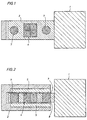
- FIGs. 1 and 2 are top and side views of a cryoisolator and illustrate one embodiment of the present invention.
- the vibration of vibrating member 1 is damped by dipole magnets 7 and multipole magnet 4 attached to vibrating member 1 and by superconductors 5 which are attached to fixed member 2.
- Superconductors 5 and magnets 4 and 7 are separated by gap 9.
- the apparatus is first assembled together with superconductors 5 in a normal nonsuperconducting state.
- Superconductors 5 are then field cooled in the presence of the magnetic fields of magnets 4 and 7. While in this instance it is preferred to field cool superconductors 5 in the presence of magnets 4 and 7, optionally, superconductors 5 could be field cooled in the presence of any suitable magnetic field whose profile would be suitable for damping the vibration of vibrating member 1.
- Dipole magnet 7 provides damping in the z direction (out of the page in FIG. 1, up the page in FIG. 2), whereas multipole magnet 4 provides damping in the x and y directions (to the right and up respectively in FIG. 1 and to the right and into the page respectively in FIG. 2).
- the apparatus of the present invention will have an effective damping coefficient that will correspond the the traditional damping coefficient of a spring model.
- the damping coefficient can be adjusted by rearranging superconductor 5 and magnets 4 and 7. Two types of arrangements of these components are the primary factors which will influence the damping coefficient.
- the first factor is the distance between the two magnets that comprise multipole magnet 4 (the two magnets are together in the embodiment shown), which corresponds to adjusting the wavevector of the dominant Fourier component of the magnetic field in gap 9.
- the second factor is the distance of gap 9 between superconductor 5 and the multipole magnet 4. Varying these two distances changes the gradient and field density which, in turn, allows control of the damping coefficient.
- Multipole magnet 4 provides high damping in the plane of the magnet superconductor interface.
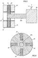
- FIG. 3 is a side view of a linear vibration absorber and illustrates another embodiment of the present invention.
- Multipole magnets 11 are attached to fixed member 10.
- Vibrating member 12 carries a station 14 to the end of which is securely affixed superconductor tube 15.
- Vibrating member 12 exhibits linear vibration in the direction as indicated by arrow 13.
- the apparatus is first assembled together with superconductor 15 in a normal nonsuperconducting state with a gap 17 between the magnet and superconducting members.
- Superconductor 15 is then field cooled in the presence of the magnetic fields of magnets 11. Again, superconductors 15 could be field cooled in the presence of any suitable magnetic field whose profile would be suitable for doping the vibration of vibrating member 12.
- the vibration of vibrating member 12 is damped as the magnetic field of magnet 11 moves through the trapped magnetic flux profile of superconductor 15.
- FIG. 5 is a side view of a radial vibration absorber and illustrates yet another embodiment of the present invention.
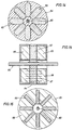
- Vibrating member 20 comprises shaft 20a on which is attached disc 30 which contains magnets 25.
- Vibrating member 20 is vibrating in the directions indicated by arrow 21.
- Fixed member 22 comprises superconductors 23 which have been field cooled in the presence of a magnetic field whose magnetic field profile is suitable for doping the vibration of vibrating member 20.
- FIG. 6 is a front view of disc 30 of FIG. 5, showing the orientation of magnets 25. The vibration of vibrating member 20 is doped as the magnetic field of magnets 25 move through the trapped magnetic flux profile of superconductors 23.
- the present invention may also be utilized in an optical system, consisting of a focal plane array together with tracking and pointing mirrors or lenses, operating under cryogenic conditions maintained by other devices such a cryoturboexpanders, turboalternators, or Stirling cycle coolers that create mechanical vibrations, degrading the resolution of the optical detection.
- FIG. 7 is a side view and FIG. 8 a front view of an apparatus in which the present invention is utilized to absorb multi-axis vibration from a pump attached to the cryogenic fluid tank.
- Cryogenic fluid tank 41 contains a cryogenic fluid such as, for example, liquid nitrogen or liquid helium.
- Cold optical sensors 43 detect light traveling along optical path 45. Attached to housing 48 are superconductors 35.
- Multipole magnets 39 are affixed to tank 41 by inner magnet holder 42b and outer magnet holder 42a, and dipole agents 37 are attached to tank 41 by magnets holders 40. A gap or spacing is provided between each magnet and each superconductor.
- Superconductors 35 have been field cooled in the presence of a magnetic field whose magnetic field profile is suitable to allow doping of the vibration of cryopump 46.
- the vibration of cryopump 46 is damped as the magnetic fields of magnets 37 and 39 move through the trapped magnetic flux in superconductors 35.
- FIG. 9 shows a variation in the magnet/superconductor arrangement for tank 41 of FIGs. 7 and 8.
- Superconductor 49 is placed within the cryogenic fluid and magnet 47 is affixed to housing 48 (shown in FIG. 7).
- FIGs. 1 through 9 have illustrated embodiments of the present invention utilized in absorbing or damping vibrations.
- the following embodiments illustrate the present invention utilized in devices such as brakes or clutches.
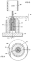
- FIG. 10 illustrates a linear superconducting magnetic clutch.
- Motor 50 drives shaft 52 to which is connected multipole magnetic shaft 53.
- Clutch member 58 comprises holder 56 and superconductor 57 which receives magnetic shaft 53.
- Space gap 54 is the distance between magnetic shaft 53 and superconductor 57.
- Superconductor 57 has been field cooled in the presence of a magnetic field whose magnetic field is suitable to allow shaft 53 to drive clutch member 58 about its rotational axis as indicated by arrow 59, as the magnetic field of magnetic shaft 53 passes through the pinned magnetic flux within superconductor 57.
- One suitable magnetic profile would be of the "checkerboard" type discussed above.
- the degree of the magnetic engagement of magnetic shaft 53 with superconductor 53 can be varied by control means 55 which allows shaft 53 to be moved in the direction indicated by arrow 51.
- control means 55 which allows shaft 53 to be moved in the direction indicated by arrow 51.
- shaft 53 is fully inside clutch member 58, the maximum magnetic engagement torque is transferred.
- shaft 53 is half way inside clutch member 58, half as much torque is transferred.
- the transfer of torque is linearly related to the degree of magnetic engagement of shaft 53 with member 58.
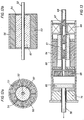
- FIG. 13 illustrates a superconductor/magnet clutch system that also utilizes a superconducting bearing.
- the bearing comprises linear bearing magnets 60 affixed to housing 64 and bearing superconductors 61 affixed to shaft 69.
- Electromagnetic coil 68 in cooperation with magnets 67 along shaft 69 are used for engaging and disengaging the clutch.
- the clutch consists of superconductor clutch pad 66 and clutch magnets 65.
- Superconductor clutch pad 66 has been field cooled in the presence of a magnetic field suitable to allow clutch pad 66 to be driven and engaged by clutch magnets 65, as the magnetic field of magnets 65 pass through the pinned magnetic flux within clutch pad 66.
- the rotational energy of shaft 69 is transferred to shaft 70, encased in member 71, through clutch pad 66 and clutch magnets 65.
- FIG. 14 shows a brake plate for a superconducting magnetic brake.
- FIG. 15 shows a superconducting magnetic brake system.
- Brake plate 84 comprises superconductors 82 that extend radially out from shaft 80. Alternating electromagnetic poles are supplied by electromagnets 85. The magnetic flux path is shown by arrows 87.
- Superconductors 82 have been field cooled in the presence of a suitable magnetic field to create a sufficient high drag torque to cause braking action as the pinned flux of the superconductors 82 is moved through the magnetic field of electromagnets 85.
- FIG. 16 shows a detail view of electromagnets 85 of FIG. 14, showing shaft 80, copper winding area 88 and Si and Fe lamination strips 89.
- the present invention can be utilized to allow motion or transportation in one plane while restraining motion in another plane.
- any of the three commonly employed techniques may be used, namely the solid state, the coprecipitation, and the sol-gel techniques.
- a description of these techniques may be found in Proceeding on the Symposium on High Temperature Superconducting Materials, University of North Carolina, Chapel Hill, N.C. , W.E. Hatfield and J.H. Miller, Jr. (Eds.), M. Dekker, New York (1988).
- An HTS material of sufficient critical current density, J c can be made by the methods disclosed in Application Serial No. 723,405, filed July 1, 1991 by W.K. Chu et al., entitled "Method for producing formed bodies of high temperature superconductors having high critical currents.
- the HTS materials of the present invention are preferably 123 materials.
- a new class of rare earth-alkaline earth-copper oxides was discovered which are superconductive at temperatures above the boiling point of liquid nitrogen, 77°K.
- These new rare earth-alkaline earth-copper oxides are now commonly referred to as "123" high-temperature superconductors in reference to the stoichiometry in which the rare earth, alkaline earth, and copper metal atoms are present, namely a ratio of 1:2:3.
- the 123 high temperature superconducting compounds have a perovskite related crystalline structure.
- the unit cell of such 123 compounds consists of three sub-cells in alignment along the crystallographic c -axis wherein the center of the middle subcell is occupied by a rare earth metal atom, the center of each end subcell is occupied by an alkaline earth metal atom, and copper atoms occupy the corner positions in each subcell.
- X-ray and neutron powder diffraction studies indicate the structure of superconductive 123 compounds to be oxygen deficient and that the ordering of oxygen in the basal planes is critical to the existence of superconducting properties in such compounds. See C. Poole et al, Copper Oxide Superconductors (John Wiley & Sons 1988).
- the resulting 123 compound assumes a tetragonal unit cell crystallographic symmetry and is non-superconductive.
- the lattice dimension of the c -axis is approximately 11.94 angstroms and that of the a and b axis is equal, approximately 3.9 angstroms.
- ⁇ is between 0.7 and 1.0, the resulting 123 compound has an orthorhombic unit cell crystallographic symmetry and is superconductive.
- the orientation of the oxygen atoms in the unit cell causes the unit cell to compress slightly along the a crystallographic axis and thus the lattice dimension of the a axis is less than that of the b axis.
- the HTS material utilized in the present invention is preferably melt-textured.
- Melt-texturing is a well known process for preparing HTS materials.
- a melt-textured growth process for preparing bodies of Y 1 Ba 2 Cu 3 O 6+ ⁇ all portions of the entire body are simultaneously first elevated in temperature beyond the peritectic temperature of the compound to melt the 123 compound incongruently into Y 2 BaCuO 5 and a liquid phase. Thereafter the body is allowed to cool, at a controlled rate (dT/dt), to a temperature below the solidus temperature wherein the Y 2 BaCuO 5 and liquid phase react to reform the 123 compound which crystallizes.
- dT/dt controlled rate
- an HTS compound fabricated into usable body shapes, such as plate, rod, wire, or ribbon, of large dimensions with controllable grain orientation and large J c to carry large total current loads.
- usable body shapes such as plate, rod, wire, or ribbon
- melt textured growth techniques since they require temperature programming of a furance in which the entire body article is placed --possess a limitation to the size of the body produced, i.e., it cannot be greater than that of the furnace. Melt textured growth and liquid-phase techniques reported so far are limited to batch production. To alleviate the impasse, one needs to fabricate the body in a continuous fashion.
- the HTS material utilized in the present invention may also be prepared by the continuous melt-texturing process of Application Serial No. 701,677, filed May 16, 1991 by C.W. Chu et. al. That process is one which continuously produces a 123 HTS compound body of desired dimensions which is in the form dictated by the application for which such body is particularly intended.
- the process of Chu et al. produces bodies composed of a 123 HTS compound in a rod/wire/ribbon/film/plate body form of any desired dimensions.
- These bodies of 123 compound are dense, of low micro-crack content, low in nonsuperconducting impurity content, and of highly aligned " ab " planes with low angle grain boundaries --i.e., of oriented grain growth; so that such 123 HTS compound bodies have the J c and total current carrying capacity required for the application for which such body shape is most suited.
- a 123 precursor composition molded to a predetermined body form is moved at a predetermined speed (dx/dt) through a furnace in which a narrow portion of such body form is, in relationship to each successive immediately adjacent narrow portion of such body form, briefly subjected to heating to a temperature T 2 of from about 80 to about 150°C above the peritectic temperature of the 123 compound as to which the composition of such body form is a precursor composition.
- the Chu et al. melt-texturing process comprises the steps of moving a preformed body composed of 123 precursor composition, preferably a composition which is precursor to the formation of or is a compound of the Y 1 Ba 2 Cu 3 O 6+ ⁇ HTS species, through a superheated zone, wherein progressively a portion of such body precursor composition first becomes rapidly superheated for a short time to a temperature greater than the peritectic temperature of the 123 species to which such body composition is a precursor; continuing movement of such body article through and out of said superheated zone at a travel rate of dx/dt to a subsequent temperature profiled zone wherein the temperature of the superheated portion of such body article form is first reduced in temperature to a temperature slightly above the peritectic temperature after which as that body portion moves through the subsequent zone the temperature of that body portion is progressively allowed to cool, by a rate of from about 0.5 °C/hours to about 3 °C/hour to a temperature of from about 60 to about 120C° below the pertitec
- Treatment of such a preshaped body article of 123 precursor composition by the Chu et al. melt-texturing process may be conducted in a continuous manner and the final 123 HTS compound shaped body article so produced has at least the minimum J c required for practical application of such shaped body article of 123 HTS compound for controlling and/or influencing relative motion between two or more members.
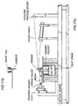
- FIG. 17a is a schematic drawing of the apparatus used to study vibrations due to forces acting between magnets and HTS materials.
- FIG. 17b is a top view of a portion of the apparatus used to study vibrations due to forces acting between magnets and HTS materials.
- the magnet was attached to a cantelever beam on one end. It was lowered to 0.3 mm above the sample plate (YBCO or Cu). Both a strain gauge and a mirror were attached to the cantelever beam to monitor the deflection of the beam. Then the displacement of the magnet and the forces acting on it can be deduced either from the electrical signals coming out of the guage, or the deflection of a laser beam reflected from the mirror.
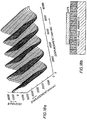
- the magnet utilized consists of strips of dipoles of alternating polarity, and is shown in FIG. 18b.
- the profile of the magnetic field (normal component) at a distance of 0.3 mm is shown in FIG. 18a.
- FIG. 19 shows the static force hysteresis loops from moving the striped magnet back and forth with a span of 0.1 mm at a distance of 0.3 mm above a sample of (a) free sintered YBCO, (b) melt-textured YBCO, and (c) melt-textured YBCO irradiated with protons at 200 MeV.
- the static force hysteresis loops show that the stiffness and the maximum force sustained increases in the order of: free sintered YBCO ⁇ melt-textured YBCO ⁇ irradiated melt-textured YBCO. It should also be noted however, that the hysteresis loop of the melt-textured YBCO is more open than that of the irradiated melt-textured YBCO.
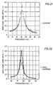
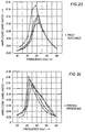
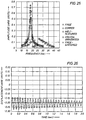
- FIGs. 20-24 show respectively the resonance responses of the cantelever beam with the striped magnet (a) only; and with a sample of (b) Cu; (c) free sintered YBCO; (d) melt-textured YBCO; (e) irradiated (200 MeV protons) melt-textured YBCO.
- FIG. 25 is a composite of FIGs. 20-24.
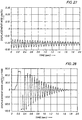
- FIGs. 26 through 30 show the natural vibrations of the cantilever beam of FIG. 17a (displacement vs. time) with the striped magnet of FIG. 18b and with respectively: (a) free beam; (b) copper; (c) free sintered YBCO; (d) melt textured YBCO; and (e) proton irradiated YBCO.
Landscapes
- Engineering & Computer Science (AREA)
- General Engineering & Computer Science (AREA)
- Mechanical Engineering (AREA)
- Physics & Mathematics (AREA)
- Chemical & Material Sciences (AREA)
- Combustion & Propulsion (AREA)
- Electromagnetism (AREA)
- Acoustics & Sound (AREA)
- Aviation & Aerospace Engineering (AREA)
- Power Engineering (AREA)
- Superconductor Devices And Manufacturing Methods Thereof (AREA)
- Magnetic Bearings And Hydrostatic Bearings (AREA)
- Earth Drilling (AREA)
- Superconductors And Manufacturing Methods Therefor (AREA)
- Vehicle Body Suspensions (AREA)
- Paper (AREA)
- Magnetic Resonance Imaging Apparatus (AREA)
- Vibration Prevention Devices (AREA)
- Braking Arrangements (AREA)
- Prostheses (AREA)
Abstract
Description
- The invention relates to an arrangement of two members in which momentum is transferred from one member to the other member as the members move relative to one another according to the preamble of
claim 1. - The document US-A-4,886,778 discloses a superconducting rotating assembly which includes a floating, unsupported and stable rotor. The rotor includes a magnetic pole at each of its extremities, each pole resting in a bearing. The polar axis of each pole is colinear with the rotating axis of the rotor. A temperature bath is provided for maintaining the bearings at or below their critical superconducting temperature, and a motive mechanism provides for rotation of the rotor. Each magnet pole is thereby levitated and adapted to rotate in a stable, non-contacting position by the field and pinning effects generated by the associated bearing. In the conventional apparatus, the arrangement of the bearing is such that no change in the polarity of flux occurs under rotation of the rotor. This is important as it avoids the imposition of displacement torques on the rotating magnets which would tend to cause the rotor to become unstable.
- The document US-A-5,071,831 showing all of the features of the preamble of
claim 1 discloses superconductive gears and clutches which exhibit no contact and which incorporate high-Tc superconducting ceramic compositions. The devices can have two discs of selected proportion, coupled to each other by a controllable magnetic field so as to transmit the desired torque in a given application, wherein the discs are composed of superconductive material. Such devices are useful in ultra-high speed rotational apparatus. - Many types of prior-art devices exist for controlling or influencing relative motion between two or more bodies. For example, vibration damping systems, brakes and clutches are well known and generally utilize mechanical type of apparatus that are subject to wear, noise, vibration and friction heating problems. These problems can often lead to seizure or other failure of the apparatus. For example, springs or shock absorbers utilized in conventional vibrational control systems tend to wear out with repeated usage over time. Brake pads and mechanical clutches ultimately wear out, and have to be periodically replaced. In additional, mechanical systems often require lubricants which fail in severe environments such as those commonly encountered in outer space. Failure of conventional liquid lubricants in outer space is usually due to the vacuum conditions that cause the lubricants to outgas or vaporize, leaving contact surfaces dry and resulting in the ultimate failure of the apparatus. Additionally, in outer space temperatures are very low so most lubricants solidify and simply do not function as lubricants.
- As an alternative to mechanical systems for controlling or influencing motion, magnetic systems have been developed. Conventional magnetic systems for controlling or influencing motion are generally unstable and require for their operability control means, such as rapidly acting feedback control systems, to compensate for displacements from the set point. Until recently, such magnetic systems have utilized magnets of two types -- either permanent magnets or electromagnets.
- Because field strength of permanent magnets is generally limited, the use of permanents magnets is limited to applications where very small forces are adequate. Electromagnets, which can supply considerably more magnetic force than comparable permanent magnets, are much more convenient to use and are thus preferred for use in conjunction with feedback control systems. However, because of the required feedback control systems, use of electromagnets adds considerably to the cost, size, and operational complexity of the system.
- It has been appreciated for years that magnetic fields strongly interact with superconducting materials. The most distinctive property of a superconductive material is its loss of electrical resistance when it is at or below a critical temperature. This critical temperature is an intrinsic property of the material and is referred to as the superconducting transition temperature of the material, Tc.
- There have been recent advances in superconducting materials and parallel advancements in the field of permanent magnets. Superconductive materials are of two basic types, designated as Type I and Type II. Unlike Type II superconductors, Type I superconductors are incapable of effecting stable suspension.
- Type I superconductors feature perfect diamagnetism up to a critical applied field, at which point superconductivity is lout and the magnetization of the sample abruptly disappears. Examples of applications of Type I materials can be found in the documents US-A-3,493,274 and US-A-3,026,151, which disclose a bearing utilizing Type I materials. In order to achieve stability in these systems, the bearing structures must rely on either a mechanical rotary support or must employ superconductors shaped to provide a laterally stable configuration.
- The recent discoveries of high temperature superconductors involve Type II materials. Whereas a Type I superconductor completely blocks out magnetic flux from its interior, a phenomenon known as diamagnetism, Type II superconductors allow a certain amount of magnetic flux to penetrate into the interior of the material, producing a stable suspension effect in addition to a levitation effect. Under such conditions, circulating superconducting currents are established within the superconductor.
- Recent research activities have brought the discovery of "high temperature superconducting" (HTS) compounds. HTS compounds are those which superconduct at and below a critical temperature, Tc, which is above the boiling point temperature of nitrogen.
- Following the discovery of superconductivity in a rare earth-alkaline earth-Cu oxide system of a perovskite crystalline structure, a new class of rare earth-alkaline earth-copper oxides was discovered which are superconductive at temperatures above the boiling point of liquid nitrogen, 77°K. These new rare earth-alkaline earth-copper oxides are now commonly referred to as "123" high-temperature superconductors in reference to the stoichiometry in which the rare earth, alkaline earth, and copper metal atoms are present, namely a ratio of 1:2:3.
- Since they are superconductive at temperatures greater than 77°K, the new CuO high temperature superconductors may be cooled with liquid nitrogen, which is a far less costly refrigerant than liquid helium. As a result, the rather complex thermal insulation and helium-recycling systems, necessary to avoid wasting the expensive helium coolant required for the low temperature superconducting material previously known, are no longer necessary. The HTS compounds simplify and enhance the reliability of commercial applications of superconductors. Liquid nitrogen is about 2000 times more efficient to use in terms of cost, when both the refrigerant itself and the associated refrigerant unit design are considered.
- A typical example of a system featuring a combination of Type II superconductors and permanent magnets is disclosed in US-A-4,886,778, which discloses a rotating shaft having two ends, each of which contains a permanent magnet and rotates in a socket clad with superconducting material. The shaft is made to levitate above the sockets by the repulsive forces which exist between the magnets and the superconductors. The incorporation of superconductors into the bearing design offers the possibility of rendering the bearings entirely passive. The design disclosed in US-A-4,886,778 has the potential for achieving very high rotational speeds, in excess of ten thousand rpm. The interaction between the rotating magnetic axial element and its stationary superconducting support takes place across a gap permeated by a strong magnetic field emanating from permanent magnets embedded in the rotating element.
- However, while systems featuring Type II superconductors and magnets have been proposed for systems designed to perpetuate motion, such as bearings, these is a need for superconductor/magnet systems for influencing and/or controlling motion.
- The present invention may be used to cause transfer of momentum between two members. The principle advantage of this invention is that such transfer of momentum is achieved without physical contact between the two members. Generally, the apparatus of the invention consists of a magnet on one of the members, and a superconductor on the other member. The superconductor has been field cooled, i.e., cooled to below its Tc in the presence of a magnetic field which then is pinned. This present invention takes advantage of the interaction between the magnetic field and the pinned flux as the magnet and the superconductor are moved relative to each other.
- Accordingly, the object underlying the present invention is to provide an apparatus for control of the relative motion between two or more members in such a manner that damping, braking or clutch engagement occurs, in other words an interaction between the members which requires momentum transfer.
- The apparatus according to the invention is defined by the features of
claim 1. Further developments of the apparatus according to the invention are specified in the subclaims. - The apparatus according to the invention has application in devices such as vibration absorption or damping devices and brakes and also in moving or transporting objects or in clutch type devices.
-
- FIGs. 1 and 2 are top and side views of a cryoisolator and illustrate one embodiment of the present invention.
- FIG. 3 is a side view of a linear vibration absorber and illustrates another embodiment of the present invention.
- FIG. 4 is a side view of a linear vibration absorber and is a variation of the linear vibration absorber of FIG. 3.
- FIG. 5 is a side view of a radial vibration absorber and illustrates yet another embodiment of the present invention.
- FIG. 6 is a front view of
disc 30 of FIG. 5, showing the orientation ofmagnets 25. - FIG. 7 is a side view and FIG. 8 a front view of an apparatus in which the present invention is utilized to absorb multi-axis vibration from a pump attached to the cryogenic fluid tank.
- FIG. 9 shows a variation in the
magnet/superconductor arrangement for
tank 41 of FIGs. 7 and 8. - FIG. 10 illustrates a linear superconducting magnetic clutch.
- FIG. 11 shows the relationship in FIG. 10 of
superconductor 57,superconductor holder 56,shaft 52,magnetic shaft 53, andair gap 54. - FIGs. 12a and 12b show portions of a clutch that is an alternate embodiment to the clutch shown in FIGs. 10 and 11.
- FIG. 13 illustrates a superconductor/magnet clutch system that also utilizes a superconducting bearing.
- FIG. 14 shows a brake plate for a superconducting magnetic brake.
- FIG. 15 shows a superconducting magnetic brake system.
- FIG. 16 shows a detail view of
electromagnets 85 of FIG. 14, showingshaft 80,copper winding area 88 and Si and Fe lamination strips 89. - FIG. 17a is a schematic drawing of the apparatus used to study vibrations due to forces acting between magnets and HTS materials.
- FIG. 17b is a top view of a portion of the apparatus used to study vibrations due to forces acting between magnets and HTS materials.
- FIG. 18a shows the profile of the magnetic field (normal componenet) of the magnet of FIG. 17, at a distance of 0.3 mm.
- FIG. 18b shows the magnet utilized in the apparatus of FIG. 17 and it consists of a strips of dipoles of alternating polarity.
- FIG. 19 shows the static force hysteresis loops from moving the striped magnet of FIG. 17 back and forth with a span of 0.1 mm at a distance of 0.3 mm above a sample of (a) free sintered Y1Ba2Cu3O6+d, where d=0.1 to 1 (hereafter "YBCO"), (b) melt-textured YBCO, and (c) melt-textured YBCO irradiated with protons at 200 MeV.
- FIGs. 20-24 show the resonance responses of the cantelever beam of FIG. 17 with the striped magnet (a) only; and with a sample of (b) Cu; (C) free sintered YBCO; (d) melt-textured YBCO; (e) irradiated (200 MeV protons) melt-textured YBCO.
- FIG. 25 is a composite of FIGs. 20-24.
- FIGs. 26 and 27 show the damping effect (displacement vs. time) for the cantilever beam of FIG. 17 comparing copper and a melt-textured superconductor, respectively.
-
- The present invention may be used to cause transfer of momentum between two members. The principle advantage of this invention is that such transfer of momentum is achieved without physical contact between the two members. Generally, the apparatus of the invention consists of a magnet on one of the members, and a superconductor on the other member. The superconductor has been field cooled, i.e., cooled to below its Tc in the presence of a magnetic field which then is pinned. This present invention takes advantage of the interaction between the magnetic field and the pinned flux as the magnet and the superconductor are moved relative to each other.
- This invention focuses on the profile of the magnetic field in the gap between the magnetic and superconducting surfaces, and the spatial Fourier decomposition of that field in particular. To increase the effective magnetic friction between these two surfaces, the magnetic surface is designed to have a magnetic field with more weight at large wavevectors. One way to achieve this is to reverse the polarity on the magnetization of the material as frequently as possible. For example in one dimension, a magnetic strip comprised of dipole magnets oriented with their dipoles parallel and with the dipoles reversed as much as possible, i.e. N-S-N-S-N-S etc, along the strip. In two dimensions, a "checkerboard" of dipole magnets with their dipoles parallel and polarity reversed as much as possible, i.e., N or S on the black checks and S or N or the white checks. Such a checkerboard or similar pattern will have application in braking or clutching apparatus. There is an optimum, though, since a magnetic field with a high wavevector will not extend very far from the magnetic surface into the superconductor, and would have a correspondingly smaller effect. Thus, it is preferred to increase the component of the magnetic field that has a wavelength in the same order as the gap distance between the magnetic and superconducting surfaces.
- FIGs. 1 and 2 are top and side views of a cryoisolator and illustrate one embodiment of the present invention. The vibration of vibrating
member 1 is damped bydipole magnets 7 andmultipole magnet 4 attached to vibratingmember 1 and bysuperconductors 5 which are attached to fixedmember 2.Superconductors 5 andmagnets gap 9. The apparatus is first assembled together withsuperconductors 5 in a normal nonsuperconducting state.Superconductors 5 are then field cooled in the presence of the magnetic fields ofmagnets cool superconductors 5 in the presence ofmagnets superconductors 5 could be field cooled in the presence of any suitable magnetic field whose profile would be suitable for damping the vibration of vibratingmember 1. -
Dipole magnet 7 provides damping in the z direction (out of the page in FIG. 1, up the page in FIG. 2), whereasmultipole magnet 4 provides damping in the x and y directions (to the right and up respectively in FIG. 1 and to the right and into the page respectively in FIG. 2). - The apparatus of the present invention will have an effective damping coefficient that will correspond the the traditional damping coefficient of a spring model. The damping coefficient can be adjusted by rearranging
superconductor 5 andmagnets gap 9. The second factor is the distance ofgap 9 betweensuperconductor 5 and themultipole magnet 4. Varying these two distances changes the gradient and field density which, in turn, allows control of the damping coefficient.Multipole magnet 4 provides high damping in the plane of the magnet superconductor interface. - FIG. 3 is a side view of a linear vibration absorber and illustrates another embodiment of the present invention.
Multipole magnets 11 are attached to fixedmember 10. Vibratingmember 12 carries astation 14 to the end of which is securely affixedsuperconductor tube 15. Vibratingmember 12 exhibits linear vibration in the direction as indicated byarrow 13. The apparatus is first assembled together withsuperconductor 15 in a normal nonsuperconducting state with agap 17 between the magnet and superconducting members.Superconductor 15 is then field cooled in the presence of the magnetic fields ofmagnets 11. Again,superconductors 15 could be field cooled in the presence of any suitable magnetic field whose profile would be suitable for doping the vibration of vibratingmember 12. The vibration of vibratingmember 12 is damped as the magnetic field ofmagnet 11 moves through the trapped magnetic flux profile ofsuperconductor 15. - FIG. 4 is a side view of a linear vibration absorber and is a variation of the linear vibration absorber of FIG. 3. Basically this embodiment illustrates that the magnets and the superconductors may be interchanged and either can be attached to the fixed or the vibrating member.
Single dipole magnet 18 is affixed to thestation 14 of vibratingmember 12 which vibrates in the direction as indicated byarrow 13. Fixedmember 10 comprisessuperconductor 15, which again has been field cooled in the presence of the magnetic field ofmagnet 18.Distance 16 shows one of the distances that will affect the damping coefficient. The vibration of vibratingmember 12 is doped as the magnetic field ofmagnet 11 moves through the trapped magnetic flux profile ofsuperconductor 15. - FIG. 5 is a side view of a radial vibration absorber and illustrates yet another embodiment of the present invention. Vibrating
member 20 comprises shaft 20a on which is attacheddisc 30 which containsmagnets 25. Vibratingmember 20 is vibrating in the directions indicated byarrow 21. Fixedmember 22 comprisessuperconductors 23 which have been field cooled in the presence of a magnetic field whose magnetic field profile is suitable for doping the vibration of vibratingmember 20. FIG. 6 is a front view ofdisc 30 of FIG. 5, showing the orientation ofmagnets 25. The vibration of vibratingmember 20 is doped as the magnetic field ofmagnets 25 move through the trapped magnetic flux profile ofsuperconductors 23. - The present invention may also be utilized in an optical system, consisting of a focal plane array together with tracking and pointing mirrors or lenses, operating under cryogenic conditions maintained by other devices such a cryoturboexpanders, turboalternators, or Stirling cycle coolers that create mechanical vibrations, degrading the resolution of the optical detection.
- FIG. 7 is a side view and FIG. 8 a front view of an apparatus in which the present invention is utilized to absorb multi-axis vibration from a pump attached to the cryogenic fluid tank.
Cryogenic fluid tank 41 contains a cryogenic fluid such as, for example, liquid nitrogen or liquid helium. Coldoptical sensors 43 detect light traveling alongoptical path 45. Attached tohousing 48 aresuperconductors 35.Multipole magnets 39 are affixed totank 41 byinner magnet holder 42b and outer magnet holder 42a, anddipole agents 37 are attached totank 41 bymagnets holders 40. A gap or spacing is provided between each magnet and each superconductor.Superconductors 35 have been field cooled in the presence of a magnetic field whose magnetic field profile is suitable to allow doping of the vibration ofcryopump 46. The vibration ofcryopump 46 is damped as the magnetic fields ofmagnets superconductors 35. - FIG. 9 shows a variation in the magnet/superconductor arrangement for
tank 41 of FIGs. 7 and 8.Superconductor 49 is placed within the cryogenic fluid andmagnet 47 is affixed to housing 48 (shown in FIG. 7). - FIGs. 1 through 9 have illustrated embodiments of the present invention utilized in absorbing or damping vibrations. The following embodiments illustrate the present invention utilized in devices such as brakes or clutches.
- FIG. 10 illustrates a linear superconducting magnetic clutch.
Motor 50drives shaft 52 to which is connected multipolemagnetic shaft 53.Clutch member 58 comprisesholder 56 andsuperconductor 57 which receivesmagnetic shaft 53.Space gap 54 is the distance betweenmagnetic shaft 53 andsuperconductor 57.Superconductor 57 has been field cooled in the presence of a magnetic field whose magnetic field is suitable to allowshaft 53 to driveclutch member 58 about its rotational axis as indicated byarrow 59, as the magnetic field ofmagnetic shaft 53 passes through the pinned magnetic flux withinsuperconductor 57. One suitable magnetic profile would be of the "checkerboard" type discussed above. The degree of the magnetic engagement ofmagnetic shaft 53 withsuperconductor 53 can be varied by control means 55 which allowsshaft 53 to be moved in the direction indicated byarrow 51. Whenshaft 53 is fully insideclutch member 58, the maximum magnetic engagement torque is transferred. Whenshaft 53 is half way insideclutch member 58, half as much torque is transferred. The transfer of torque is linearly related to the degree of magnetic engagement ofshaft 53 withmember 58. - FIG. 11 shows the relationship in FIG. 10 of
superconductor 57,superconductor holder 56,shaft 52,magnetic shaft 53, andgap 54. - FIGs. 12a and 12b show portions of a clutch that is an alternate embodiment to the clutch shown in FIGs. 10 and 11. In this embodiment, the positions of the superconductor and the magnets are reversed.
Superconductor 57 is located onshaft 52, and themagnets 53 are located on the clutch member and secured in place byholder 56.Gap 54 is the distance betweensuperconductor 57 andmagnets 53. - FIG. 13 illustrates a superconductor/magnet clutch system that also utilizes a superconducting bearing. The bearing comprises
linear bearing magnets 60 affixed tohousing 64 andbearing superconductors 61 affixed toshaft 69.Electromagnetic coil 68 in cooperation withmagnets 67 alongshaft 69 are used for engaging and disengaging the clutch. The clutch consists of superconductorclutch pad 66 andclutch magnets 65. Superconductorclutch pad 66 has been field cooled in the presence of a magnetic field suitable to allowclutch pad 66 to be driven and engaged byclutch magnets 65, as the magnetic field ofmagnets 65 pass through the pinned magnetic flux withinclutch pad 66. The rotational energy ofshaft 69 is transferred toshaft 70, encased inmember 71, throughclutch pad 66 andclutch magnets 65. - FIG. 14 shows a brake plate for a superconducting magnetic brake. FIG. 15 shows a superconducting magnetic brake system.
Brake plate 84 comprisessuperconductors 82 that extend radially out fromshaft 80. Alternating electromagnetic poles are supplied byelectromagnets 85. The magnetic flux path is shown byarrows 87.Superconductors 82 have been field cooled in the presence of a suitable magnetic field to create a sufficient high drag torque to cause braking action as the pinned flux of thesuperconductors 82 is moved through the magnetic field ofelectromagnets 85. - FIG. 16 shows a detail view of
electromagnets 85 of FIG. 14, showingshaft 80,copper winding area 88 and Si and Fe lamination strips 89. - With the proper geometric arrangement and orientation of magnets, the present invention can be utilized to allow motion or transportation in one plane while restraining motion in another plane.
- To prepare the precursor composition from which the HTS compound will be prepared, any of the three commonly employed techniques may be used, namely the solid state, the coprecipitation, and the sol-gel techniques. A description of these techniques may be found in Proceeding on the Symposium on High Temperature Superconducting Materials, University of North Carolina, Chapel Hill, N.C., W.E. Hatfield and J.H. Miller, Jr. (Eds.), M. Dekker, New York (1988). An HTS material of sufficient critical current density, Jc, can be made by the methods disclosed in Application Serial No. 723,405, filed July 1, 1991 by W.K. Chu et al., entitled "Method for producing formed bodies of high temperature superconductors having high critical currents.
- The HTS materials of the present invention are preferably 123 materials. Following the discovery of superconductivity in a rare earth-alkaline earth-Cu oxide system of a perovskite crystalline structure, a new class of rare earth-alkaline earth-copper oxides was discovered which are superconductive at temperatures above the boiling point of liquid nitrogen, 77°K. These new rare earth-alkaline earth-copper oxides are now commonly referred to as "123" high-temperature superconductors in reference to the stoichiometry in which the rare earth, alkaline earth, and copper metal atoms are present, namely a ratio of 1:2:3.
- The 123 high temperature superconducting compounds have a perovskite related crystalline structure. The unit cell of such 123 compounds consists of three sub-cells in alignment along the crystallographic c-axis wherein the center of the middle subcell is occupied by a rare earth metal atom, the center of each end subcell is occupied by an alkaline earth metal atom, and copper atoms occupy the corner positions in each subcell. X-ray and neutron powder diffraction studies indicate the structure of superconductive 123 compounds to be oxygen deficient and that the ordering of oxygen in the basal planes is critical to the existence of superconducting properties in such compounds. See C. Poole et al, Copper Oxide Superconductors (John Wiley & Sons 1988).
- The unit cell formula of the 123 compound is L1M2Cu3O6+δ (δ = 0.1 to 1.0, preferably about 1.0) wherein the rare earth metal constituent, L, is yttrium, lanthanum, neodymium, samarium, europium, gadolinium, dysprosium, holmium, erbium, thulium, ytterbium, or lutetium, or mixtures thereof including mixtures with scandium, cerium, praseodymium, terbium and the alkaline earth constituent, M, is barium, strontium or mixtures thereof. Studies indicate that when δ is between about 0.1 to about 0.6, the resulting 123 compound assumes a tetragonal unit cell crystallographic symmetry and is non-superconductive. In the tetragonal unit cell symmetry, the lattice dimension of the c-axis is approximately 11.94 angstroms and that of the a and b axis is equal, approximately 3.9 angstroms. When δ is between 0.7 and 1.0, the resulting 123 compound has an orthorhombic unit cell crystallographic symmetry and is superconductive. The orientation of the oxygen atoms in the unit cell causes the unit cell to compress slightly along the a crystallographic axis and thus the lattice dimension of the a axis is less than that of the b axis. Lattice constants in the orthorhombic symmetry are about a = 3.82, b = 3.89 and c = 11.55 angstroms.
- The HTS material utilized in the present invention is preferably melt-textured. Melt-texturing is a well known process for preparing HTS materials. In a melt-textured growth process for preparing bodies of Y1Ba2Cu3O6+δ all portions of the entire body are simultaneously first elevated in temperature beyond the peritectic temperature of the compound to melt the 123 compound incongruently into Y2BaCuO5 and a liquid phase. Thereafter the body is allowed to cool, at a controlled rate (dT/dt), to a temperature below the solidus temperature wherein the Y2BaCuO5 and liquid phase react to reform the 123 compound which crystallizes. In the melt-textured growth process reported by Jin et al. in Appl. Phys. Lett., Vol. 52, pp. 2074-2076(1988) and Vol. 54, pp. 584-586 (1989) and Murakami et al. in Jpn. J. Appl. Phys., Vol. 28, pp. L1125-1127 (1989) the entire body of 123 compound is first heated above the solidus or peritectic temperature and thereafter the entire body is subjected to a not well defined thermal gradient to promote directional solidification of the 123 grains as the body is permitted to cool at a controlled rate to a temperature below the solidus temperature. With such melt-textured growth procedure Jin et al. has reported bodies prepared with a zero field transport critical current density at 77 K of 17,000 A/cm2. Others have employed a modified version of melt texture growth wherein after an entire body has first been heated to a temperature above the peritectic temperature the body compound is then cooled at a time cotrolled rate without being subjected to a thermal gradient. See, Salama et al., Appl. Phys. Lett., vol. 54, pp. 2352-2354. The procedure of Salama et al. reports the formation of Y1Ba2Cu3O6+δ bodies having current densities in excess of 37,000 A/cm2 in a magnetic field of 6000 G. Salama at al., emphasize grain growth by cooling of the body at a time controlled rate in the absence of an imposed thermal gradient (dT/dx) upon the body.
- By use of a "melt textured growth" process, a number of groups have reported making 123 compound bodies of enhanced Jc. To date the highest reported Jc of a 123 body prepared by a melt textured growth technique is 1.7 x 10⁴ A/cm2 by Jin et al., Phys. Rev. B., Vol. 37, pp. 7850-7853 (1988) and Appl. Phys. Lett., Vol. 42, pp. 2074-2076 (1988); later Salama et al. employed a liquid-phase processing method to obtain a Jc ∼ 7.5 x 10⁴ A/cm2; both in bulk YBa2Cu3O7-δ (Y123) at 0 T and 77 K after prolonged oxygen annealing. In each method of body treatment the enhanced Jc has been ascribed to the drastically improved grain alignment, phase purity, and densification in Y1Ba2Cu3O6+δ compound of which the body is composed.
- In certain applications for controlling and/or influencing motion utilizing the present invention, it may be necessary to have an HTS compound fabricated into usable body shapes, such as plate, rod, wire, or ribbon, of large dimensions with controllable grain orientation and large Jc to carry large total current loads. Although promising for 123 bodies of enhanced Jc, the melt textured growth techniques--since they require temperature programming of a furance in which the entire body article is placed --possess a limitation to the size of the body produced, i.e., it cannot be greater than that of the furnace. Melt textured growth and liquid-phase techniques reported so far are limited to batch production. To alleviate the impasse, one needs to fabricate the body in a continuous fashion.
- The HTS material utilized in the present invention may also be prepared by the continuous melt-texturing process of Application Serial No. 701,677, filed May 16, 1991 by C.W. Chu et. al. That process is one which continuously produces a 123 HTS compound body of desired dimensions which is in the form dictated by the application for which such body is particularly intended.
- The process of Chu et al. produces bodies composed of a 123 HTS compound in a rod/wire/ribbon/film/plate body form of any desired dimensions. These bodies of 123 compound are dense, of low micro-crack content, low in nonsuperconducting impurity content, and of highly aligned "ab" planes with low angle grain boundaries --i.e., of oriented grain growth; so that such 123 HTS compound bodies have the Jc and total current carrying capacity required for the application for which such body shape is most suited.
- To enable the continuous growth of a 123 compound body of large dimensions with a pre-determined body form to carry large Jc and to provide the capability for the removal of impurity phases, a 123 precursor composition molded to a predetermined body form is moved at a predetermined speed (dx/dt) through a furnace in which a narrow portion of such body form is, in relationship to each successive immediately adjacent narrow portion of such body form, briefly subjected to heating to a temperature T2 of from about 80 to about 150°C above the peritectic temperature of the 123 compound as to which the composition of such body form is a precursor composition. As that so superheated portion of the body moves out of the T2 superheated zone into a zone having a preset temperature gradient profile (dT/dx), that superheated body portion is rapidly cooled to a temperature T3 which is about 10 to 40C° ("C°" meaning a range of temperature above or below a particular temperature, °C) above the peritectic temperature of the 123 HTS species. As that portion of the body advances through the second zone its temperature is reduced to a final second zone temperature of T4 which is about 60 to 120C° below the peritectic temperature. At all times while in the zone of present temperature gradient profile all portions of the body in such zone are subject to a pre-set temperature gradient (dT/dx) while such body portions undergo cooling according to a rate (dT/dt) controllable in tens of the traversing speed (dx/dt) through such zone. The presence of a preset temperature gradient profile, dT/dx, determines the grain growth direction of 123 grains in the body form. Both the rate of body travel, dx/dt, and the profile of the preset temperature gradient, dT/dx, are chosen to give the desired dT/dt for highly aligned grain growth.
- The Chu et al. melt-texturing process comprises the steps of moving a preformed body composed of 123 precursor composition, preferably a composition which is precursor to the formation of or is a compound of the Y1Ba2Cu3O6+δ HTS species, through a superheated zone, wherein progressively a portion of such body precursor composition first becomes rapidly superheated for a short time to a temperature greater than the peritectic temperature of the 123 species to which such body composition is a precursor; continuing movement of such body article through and out of said superheated zone at a travel rate of dx/dt to a subsequent temperature profiled zone wherein the temperature of the superheated portion of such body article form is first reduced in temperature to a temperature slightly above the peritectic temperature after which as that body portion moves through the subsequent zone the temperature of that body portion is progressively allowed to cool, by a rate of from about 0.5 °C/hours to about 3 °C/hour to a temperature of from about 60 to about 120C° below the pertitectic point of the 123 HTS compound of which such portion of said body is composed; and, preferably, exposing said body portion while at a temperature of about 400C° below the peritectic point of said 123 compound of which said body is composed to an oxygen atmosphere until said portion of the body reaches a temperature of about 400°C and continuing movement of such body article until all portions of such body are passed through said superheated zone, said temperature profiled subsequent zone and preferably, through said oxygen containing atmosphere.
- Treatment of such a preshaped body article of 123 precursor composition by the Chu et al. melt-texturing process may be conducted in a continuous manner and the final 123 HTS compound shaped body article so produced has at least the minimum Jc required for practical application of such shaped body article of 123 HTS compound for controlling and/or influencing relative motion between two or more members.
- FIG. 17a is a schematic drawing of the apparatus used to study vibrations due to forces acting between magnets and HTS materials. FIG. 17b is a top view of a portion of the apparatus used to study vibrations due to forces acting between magnets and HTS materials. The magnet was attached to a cantelever beam on one end. It was lowered to 0.3 mm above the sample plate (YBCO or Cu). Both a strain gauge and a mirror were attached to the cantelever beam to monitor the deflection of the beam. Then the displacement of the magnet and the forces acting on it can be deduced either from the electrical signals coming out of the guage, or the deflection of a laser beam reflected from the mirror. For quasi-static measurements the magnet can be moved by a stepper motor, to which the other end of the cantelever beam is attached. To measure the resonance response of the beam-magnet-sample system, vibrations are forced upon the ben via another permanent magnet and an electrical coil. Finally, natural vibrations can be studied by starting the motion with a random tap on the beam, usually with extra mass attached.
- The magnet utilized consists of strips of dipoles of alternating polarity, and is shown in FIG. 18b. The profile of the magnetic field (normal component) at a distance of 0.3 mm is shown in FIG. 18a.
- FIG. 19 shows the static force hysteresis loops from moving the striped magnet back and forth with a span of 0.1 mm at a distance of 0.3 mm above a sample of (a) free sintered YBCO, (b) melt-textured YBCO, and (c) melt-textured YBCO irradiated with protons at 200 MeV. The static force hysteresis loops show that the stiffness and the maximum force sustained increases in the order of: free sintered YBCO < melt-textured YBCO < irradiated melt-textured YBCO. It should also be noted however, that the hysteresis loop of the melt-textured YBCO is more open than that of the irradiated melt-textured YBCO.
- FIGs. 20-24 show respectively the resonance responses of the cantelever beam with the striped magnet (a) only; and with a sample of (b) Cu; (c) free sintered YBCO; (d) melt-textured YBCO; (e) irradiated (200 MeV protons) melt-textured YBCO. FIG. 25 is a composite of FIGs. 20-24.
- FIGs. 26 through 30 show the natural vibrations of the cantilever beam of FIG. 17a (displacement vs. time) with the striped magnet of FIG. 18b and with respectively: (a) free beam; (b) copper; (c) free sintered YBCO; (d) melt textured YBCO; and (e) proton irradiated YBCO.
- The invention has been described with reference to its preferred embodiments. One skilled in the art may appreciate from this description changes or variations which may be made which do not depart from the scope of the invention claimed hereafter.
Claims (7)
- An arrangement of two members in which momentum is transferred from one member to the other member and the members move relative to one another, comprising:magnet means (4, 7, 11, 53) affixed to one (1, 12, 52) of the members and having a magnetic field profile; anda superconductor (5, 15, 57) which is affixed to the other member (2, 12, 58) and which has been field cooled in the presence of a magnetic field, thereby pinning the magnetic flux profile;
wherein, as the one member is moved past the other member, the magnetic field profile of the magnet means (4, 7, 11, 53) will move through the pinned magnetic flux profile, so as to cause momentum to be transferred between the members,
characterized in thatthe magnetic field profile of the magnet means (4, 7, 11, 53) is of non-uniform field strength in that it changes along a direction corresponding to the relative movement of the two members. - The arrangement of Claim 1, wherein the superconductor has been field cooled in the presence of the magnetic field profile of the magnet means (4, 7, 11, 53) affixed to the first member (1, 12, 52).
- The arrangement of Claim 1 or 2, wherein the superconductor (5, 15, 57) is a type II superconductor.
- The arrangement of Claim 1, 2 or 3, wherein the superconductor (5, 15, 57) comprises a copper oxide.
- The arrangement of Claim 1, 2 or 3, wherein the superconductor (5, 15, 57) comprises a 123 high temperature superconductor.
- The arrangement of any one of the Claims 1 to 5, wherein the superconductor (5, 15, 57) is field cooled in the presence of a magnetic field having a checkerboard pattern.
- The arrangement of any one of the Claims 1 to 6, wherein one member comprises a clutch plate (65) and the other member comprises a clutch pad (66).
Applications Claiming Priority (3)
| Application Number | Priority Date | Filing Date | Title |
|---|---|---|---|
| US802090 | 1991-12-03 | ||
| US07/802,090 US5542506A (en) | 1991-12-03 | 1991-12-03 | Magnet-superconductor systems for controlling and influencing relative motion |
| PCT/US1992/010356 WO1993011372A1 (en) | 1991-12-03 | 1992-12-01 | Magnet-superconductor systems for controlling and influencing relative motion |
Publications (3)
| Publication Number | Publication Date |
|---|---|
| EP0614514A1 EP0614514A1 (en) | 1994-09-14 |
| EP0614514A4 EP0614514A4 (en) | 1996-06-26 |
| EP0614514B1 true EP0614514B1 (en) | 2000-03-15 |
Family
ID=25182816
Family Applications (1)
| Application Number | Title | Priority Date | Filing Date |
|---|---|---|---|
| EP93900791A Expired - Lifetime EP0614514B1 (en) | 1991-12-03 | 1992-12-01 | Magnet-superconductor systems for controlling and influencing relative motion |
Country Status (9)
| Country | Link |
|---|---|
| US (2) | US5542506A (en) |
| EP (1) | EP0614514B1 (en) |
| JP (1) | JPH07505205A (en) |
| KR (1) | KR100282088B1 (en) |
| AT (1) | ATE190702T1 (en) |
| AU (1) | AU674502B2 (en) |
| CA (1) | CA2124956A1 (en) |
| DE (1) | DE69230800T2 (en) |
| WO (1) | WO1993011372A1 (en) |
Families Citing this family (31)
| Publication number | Priority date | Publication date | Assignee | Title |
|---|---|---|---|---|
| US5542506A (en) * | 1991-12-03 | 1996-08-06 | University Of Houston-University Park | Magnet-superconductor systems for controlling and influencing relative motion |
| US5788029A (en) * | 1993-08-18 | 1998-08-04 | Bell Helicopter | Vibration isolation system |
| US5747426A (en) * | 1995-06-07 | 1998-05-05 | Commonwealth Research Corporation | High performance magnetic bearing systems using high temperature superconductors |
| FR2740349B1 (en) * | 1995-10-30 | 1997-11-21 | Dynastar Skis Sa | VIBRATION DAMPING DEVICE FOR MOUNTING ON A SPORTS ARTICLE |
| US5726512A (en) * | 1996-10-04 | 1998-03-10 | The University Of Houston System | Vibration-free levitated platform |
| US6079267A (en) * | 1998-11-06 | 2000-06-27 | The United States Of America As Represented By The United States Department Of Energy | Method and apparatus for measuring gravitational acceleration utilizing a high temperature superconducting bearing |
| JP2000337434A (en) * | 1999-05-25 | 2000-12-05 | Delta Tooling Co Ltd | Vibration mechanism |
| US20030019700A1 (en) * | 2001-07-25 | 2003-01-30 | Michael Wittig | Magnetorheological fluid damper |
| US20030163558A1 (en) * | 2002-02-25 | 2003-08-28 | Docomo Communications Laboratories Usa, Inc. | System and method for Hyper Operator controlled network probing across overlaid heterogeneous access networks |
| DE10214325A1 (en) * | 2002-03-28 | 2003-10-16 | Zf Lemfoerder Metallwaren Ag | Method for operating a hydraulic bearing and bearing designed therefor |
| US6800321B1 (en) * | 2002-05-29 | 2004-10-05 | The Regents Of The University Of California | Reduced AC losses in HTS coated conductors |
| JP3976250B2 (en) * | 2002-06-11 | 2007-09-12 | 株式会社 東北テクノアーチ | Damper using magnetic fluid |
| US6794778B1 (en) * | 2003-05-23 | 2004-09-21 | Harmonic Design, Inc. | Braking system for powered window covering |
| US7259485B2 (en) * | 2003-05-23 | 2007-08-21 | Somfy Sas | Magnetic brake for window covering powered by DC motor |
| US7002310B2 (en) * | 2004-02-25 | 2006-02-21 | Somfy Sas | Piezo-based encoder with magnetic brake for powered window covering |
| US20060243549A1 (en) * | 2005-04-28 | 2006-11-02 | Honeywell International, Inc. | Magnetic bearings for damping and/or isolation systems |
| DE102006028181B4 (en) * | 2006-06-16 | 2014-09-11 | Sterki Ag | Gear set for a gearbox |
| CN100482550C (en) * | 2006-11-03 | 2009-04-29 | 中国科学院电工研究所 | Shock reducing method for super conductive magnet |
| KR20100026655A (en) * | 2008-09-01 | 2010-03-10 | 삼성모바일디스플레이주식회사 | Mask for thin film deposition and manufacturing method of oled using the same |
| JP5268109B2 (en) * | 2009-03-23 | 2013-08-21 | 国立大学法人東北大学 | Seismic isolation / vibration isolation device |
| US8327983B1 (en) | 2009-09-14 | 2012-12-11 | Exelis, Inc. | Enhanced damping using motion amplification |
| US20110147146A1 (en) | 2009-12-17 | 2011-06-23 | Itt Manufacturing Enterprises, Inc. | Enhanced damping using cryogenic cooling |
| EP2526611B1 (en) * | 2010-01-19 | 2018-11-07 | Rolls-Royce plc | Magnetic gear arrangement |
| WO2016019968A1 (en) * | 2014-08-07 | 2016-02-11 | Festo Ag & Co. Kg | Conveying apparatus with a superconductor/permanent magnet drive arrangement |
| CN104343875A (en) * | 2014-10-17 | 2015-02-11 | 上海佐林电器有限公司 | Linear damper |
| WO2016138915A1 (en) * | 2015-03-04 | 2016-09-09 | Festo Ag & Co. Kg | Clamping device and use of a clamping device |
| CN105300567A (en) * | 2015-09-23 | 2016-02-03 | 西南交通大学 | High-gradient high-intensity magnetic field magnetic suspension characteristic test technology |
| UA116741U (en) * | 2016-08-05 | 2017-06-12 | Вадим Юрійович Цивіліцин | MAGNETIC SPRING |
| US10364860B2 (en) * | 2017-12-08 | 2019-07-30 | The Boeing Company | Systems and methods for dampening dynamic loading |
| DE102018216347A1 (en) | 2018-09-25 | 2020-03-26 | Carl Zeiss Smt Gmbh | Projection exposure system for semiconductor lithography with a magnetic damping arrangement |
| US11852212B2 (en) * | 2019-04-22 | 2023-12-26 | Invetech, Inc. | Adjustable magnetic counterbalance |
Citations (1)
| Publication number | Priority date | Publication date | Assignee | Title |
|---|---|---|---|---|
| US3493274A (en) * | 1967-12-18 | 1970-02-03 | Little Inc A | Magnetic support systems |
Family Cites Families (13)
| Publication number | Priority date | Publication date | Assignee | Title |
|---|---|---|---|---|
| US3589300A (en) * | 1968-10-25 | 1971-06-29 | North American Rockwell | Magnetic suspension system |
| JPS5610844A (en) * | 1979-07-02 | 1981-02-03 | Toyota Motor Corp | Feedback control system vibration absorbing suspension |
| JPS62203730A (en) * | 1986-03-03 | 1987-09-08 | Toyota Motor Corp | Bearing forcedly fitting method for steering joint |
| JPH01203730A (en) * | 1988-02-09 | 1989-08-16 | Nec Corp | Damper gear |
| SU1597464A1 (en) * | 1988-07-14 | 1990-10-07 | Новосибирский Институт Советской Кооперативной Торговли | Magnetic vibroinsulator |
| US4886778A (en) * | 1988-08-01 | 1989-12-12 | Cornell Research Foundation Inc. | Superconducting rotating assembly |
| JPH02150526A (en) * | 1988-11-29 | 1990-06-08 | Showa Electric Wire & Cable Co Ltd | Vibration isolator |
| US5071831A (en) * | 1989-01-19 | 1991-12-10 | International Superconductor Corp. | Superconductive gears and clutches |
| US4979445A (en) * | 1989-01-26 | 1990-12-25 | Giovanni Lanzara | Magnetically levitated vehicle with superconducting mirror sheets interacting with guideway magnetic fields |
| US5122509A (en) * | 1990-04-30 | 1992-06-16 | Advanced Technology Materials, Inc. | High temperature superconductor/diamond composite article, and method of making the same |
| JP2893291B2 (en) * | 1990-09-03 | 1999-05-17 | 光洋精工株式会社 | Braking device |
| US5130588A (en) * | 1991-02-06 | 1992-07-14 | Allied-Signal Inc. | Cylindrical composite superconductor bearing |
| US5542506A (en) * | 1991-12-03 | 1996-08-06 | University Of Houston-University Park | Magnet-superconductor systems for controlling and influencing relative motion |
-
1991
- 1991-12-03 US US07/802,090 patent/US5542506A/en not_active Expired - Fee Related
-
1992
- 1992-12-01 DE DE69230800T patent/DE69230800T2/en not_active Expired - Fee Related
- 1992-12-01 JP JP5510308A patent/JPH07505205A/en active Pending
- 1992-12-01 CA CA002124956A patent/CA2124956A1/en not_active Abandoned
- 1992-12-01 AU AU32326/93A patent/AU674502B2/en not_active Ceased
- 1992-12-01 KR KR1019940701889A patent/KR100282088B1/en not_active Expired - Fee Related
- 1992-12-01 AT AT93900791T patent/ATE190702T1/en not_active IP Right Cessation
- 1992-12-01 EP EP93900791A patent/EP0614514B1/en not_active Expired - Lifetime
- 1992-12-01 WO PCT/US1992/010356 patent/WO1993011372A1/en not_active Ceased
-
1995
- 1995-08-29 US US08/521,300 patent/US5947237A/en not_active Expired - Fee Related
Patent Citations (1)
| Publication number | Priority date | Publication date | Assignee | Title |
|---|---|---|---|---|
| US3493274A (en) * | 1967-12-18 | 1970-02-03 | Little Inc A | Magnetic support systems |
Also Published As
| Publication number | Publication date |
|---|---|
| JPH07505205A (en) | 1995-06-08 |
| AU674502B2 (en) | 1997-01-02 |
| EP0614514A4 (en) | 1996-06-26 |
| US5542506A (en) | 1996-08-06 |
| DE69230800T2 (en) | 2000-11-16 |
| ATE190702T1 (en) | 2000-04-15 |
| WO1993011372A1 (en) | 1993-06-10 |
| CA2124956A1 (en) | 1993-06-10 |
| US5947237A (en) | 1999-09-07 |
| AU3232693A (en) | 1993-06-28 |
| DE69230800D1 (en) | 2000-04-20 |
| EP0614514A1 (en) | 1994-09-14 |
| KR100282088B1 (en) | 2001-03-02 |
Similar Documents
| Publication | Publication Date | Title |
|---|---|---|
| US5542506A (en) | Magnet-superconductor systems for controlling and influencing relative motion | |
| US5126317A (en) | Bearing system employing a superconductor element | |
| AU656499B2 (en) | Opposed-magnet bearing with interposed superconductor | |
| Hull et al. | Applications of bulk high-temperature superconductors | |
| US5831362A (en) | Magnet-superconductor flywheel and levitation systems | |
| US5177387A (en) | High temperature superconducting magnetic bearings | |
| Werfel et al. | Large-scale HTS bulks for magnetic application | |
| US5710469A (en) | Magnetic bearing element for a rotor shaft using high-TC superconducting materials | |
| CA2114230A1 (en) | Flywheel energy storage with superconductor magnetic bearings | |
| JPH11507710A (en) | High performance magnetic bearing system using high temperature superconductor | |
| US5726512A (en) | Vibration-free levitated platform | |
| Nariki et al. | Development of high-performance QMG bulk magnets for high magnetic field engineering applications | |
| US5479059A (en) | Thin film superconductor magnetic bearings | |
| US20060087179A1 (en) | Engine using the transition state of a superconductor to produce energy | |
| Werfel et al. | Encapsulated HTS bearings: technical and cost considerations | |
| Guner et al. | Lateral force measurements for (Gd123) 1− x:(Gd211) x superconductors at different temperatures | |
| Ma et al. | Magnetic interaction force between high-Tc superconductor-ring and magnet | |
| Hekmati et al. | Structures for high temperature superconducting magnetic bearings | |
| JPH1174114A (en) | Superconductor magnet device | |
| Agil et al. | The flux pinning energy studies of (Mo/W) co-doping bulk BPSCCO superconductor | |
| US8575808B2 (en) | Electric motor comprising an inductor with a superconducting element incorporated between coils | |
| Hong et al. | Development of superconductor application technology | |
| KR930009527B1 (en) | Contactless bearing and shaft rotation drive using high temperature superconductor | |
| Murakami | Superconductivity Research Laboratory | |
| Matsumoto et al. | Fabrication of a variable-field-direction superconducting magnet |
Legal Events
| Date | Code | Title | Description |
|---|---|---|---|
| PUAI | Public reference made under article 153(3) epc to a published international application that has entered the european phase |
Free format text: ORIGINAL CODE: 0009012 |
|
| 17P | Request for examination filed |
Effective date: 19940617 |
|
| AK | Designated contracting states |
Kind code of ref document: A1 Designated state(s): AT BE CH DE DK ES FR GB GR IE IT LI LU MC NL PT SE |
|
| A4 | Supplementary search report drawn up and despatched |
Effective date: 19960506 |
|
| AK | Designated contracting states |
Kind code of ref document: A4 Designated state(s): AT BE CH DE DK ES FR GB GR IE IT LI LU MC NL PT SE |
|
| 17Q | First examination report despatched |
Effective date: 19970605 |
|
| GRAG | Despatch of communication of intention to grant |
Free format text: ORIGINAL CODE: EPIDOS AGRA |
|
| GRAG | Despatch of communication of intention to grant |
Free format text: ORIGINAL CODE: EPIDOS AGRA |
|
| GRAH | Despatch of communication of intention to grant a patent |
Free format text: ORIGINAL CODE: EPIDOS IGRA |
|
| GRAH | Despatch of communication of intention to grant a patent |
Free format text: ORIGINAL CODE: EPIDOS IGRA |
|
| GRAA | (expected) grant |
Free format text: ORIGINAL CODE: 0009210 |
|
| AK | Designated contracting states |
Kind code of ref document: B1 Designated state(s): AT BE CH DE DK ES FR GB GR IE IT LI LU MC NL PT SE |
|
| PG25 | Lapsed in a contracting state [announced via postgrant information from national office to epo] |
Ref country code: SE Free format text: THE PATENT HAS BEEN ANNULLED BY A DECISION OF A NATIONAL AUTHORITY Effective date: 20000315 Ref country code: NL Free format text: LAPSE BECAUSE OF FAILURE TO SUBMIT A TRANSLATION OF THE DESCRIPTION OR TO PAY THE FEE WITHIN THE PRESCRIBED TIME-LIMIT Effective date: 20000315 Ref country code: LI Free format text: LAPSE BECAUSE OF NON-PAYMENT OF DUE FEES Effective date: 20000315 Ref country code: GR Free format text: LAPSE BECAUSE OF NON-PAYMENT OF DUE FEES Effective date: 20000315 Ref country code: ES Free format text: THE PATENT HAS BEEN ANNULLED BY A DECISION OF A NATIONAL AUTHORITY Effective date: 20000315 Ref country code: CH Free format text: LAPSE BECAUSE OF NON-PAYMENT OF DUE FEES Effective date: 20000315 Ref country code: BE Free format text: LAPSE BECAUSE OF FAILURE TO SUBMIT A TRANSLATION OF THE DESCRIPTION OR TO PAY THE FEE WITHIN THE PRESCRIBED TIME-LIMIT Effective date: 20000315 Ref country code: AT Free format text: LAPSE BECAUSE OF FAILURE TO SUBMIT A TRANSLATION OF THE DESCRIPTION OR TO PAY THE FEE WITHIN THE PRESCRIBED TIME-LIMIT Effective date: 20000315 |
|
| REF | Corresponds to: |
Ref document number: 190702 Country of ref document: AT Date of ref document: 20000415 Kind code of ref document: T |
|
| REG | Reference to a national code |
Ref country code: CH Ref legal event code: EP |
|
| REF | Corresponds to: |
Ref document number: 69230800 Country of ref document: DE Date of ref document: 20000420 |
|
| REG | Reference to a national code |
Ref country code: IE Ref legal event code: FG4D |
|
| ITF | It: translation for a ep patent filed | ||
| PG25 | Lapsed in a contracting state [announced via postgrant information from national office to epo] |
Ref country code: PT Free format text: LAPSE BECAUSE OF FAILURE TO SUBMIT A TRANSLATION OF THE DESCRIPTION OR TO PAY THE FEE WITHIN THE PRESCRIBED TIME-LIMIT Effective date: 20000615 Ref country code: DK Free format text: LAPSE BECAUSE OF FAILURE TO SUBMIT A TRANSLATION OF THE DESCRIPTION OR TO PAY THE FEE WITHIN THE PRESCRIBED TIME-LIMIT Effective date: 20000615 |
|
| ET | Fr: translation filed | ||
| NLV1 | Nl: lapsed or annulled due to failure to fulfill the requirements of art. 29p and 29m of the patents act | ||
| REG | Reference to a national code |
Ref country code: CH Ref legal event code: PL |
|
| PGFP | Annual fee paid to national office [announced via postgrant information from national office to epo] |
Ref country code: MC Payment date: 20001122 Year of fee payment: 9 |
|
| PGFP | Annual fee paid to national office [announced via postgrant information from national office to epo] |
Ref country code: IE Payment date: 20001130 Year of fee payment: 9 |
|
| PLBE | No opposition filed within time limit |
Free format text: ORIGINAL CODE: 0009261 |
|
| STAA | Information on the status of an ep patent application or granted ep patent |
Free format text: STATUS: NO OPPOSITION FILED WITHIN TIME LIMIT |
|
| PGFP | Annual fee paid to national office [announced via postgrant information from national office to epo] |
Ref country code: LU Payment date: 20010212 Year of fee payment: 9 |
|
| 26N | No opposition filed | ||
| PG25 | Lapsed in a contracting state [announced via postgrant information from national office to epo] |
Ref country code: MC Free format text: LAPSE BECAUSE OF NON-PAYMENT OF DUE FEES Effective date: 20011201 Ref country code: LU Free format text: LAPSE BECAUSE OF NON-PAYMENT OF DUE FEES Effective date: 20011201 |
|
| PG25 | Lapsed in a contracting state [announced via postgrant information from national office to epo] |
Ref country code: IE Free format text: LAPSE BECAUSE OF FAILURE TO SUBMIT A TRANSLATION OF THE DESCRIPTION OR TO PAY THE FEE WITHIN THE PRESCRIBED TIME-LIMIT Effective date: 20011203 |
|
| REG | Reference to a national code |
Ref country code: GB Ref legal event code: IF02 |
|
| REG | Reference to a national code |
Ref country code: IE Ref legal event code: MM4A |
|
| PGFP | Annual fee paid to national office [announced via postgrant information from national office to epo] |
Ref country code: FR Payment date: 20021119 Year of fee payment: 11 |
|
| PGFP | Annual fee paid to national office [announced via postgrant information from national office to epo] |
Ref country code: GB Payment date: 20021127 Year of fee payment: 11 |
|
| PGFP | Annual fee paid to national office [announced via postgrant information from national office to epo] |
Ref country code: DE Payment date: 20021230 Year of fee payment: 11 |
|
| PG25 | Lapsed in a contracting state [announced via postgrant information from national office to epo] |
Ref country code: GB Free format text: LAPSE BECAUSE OF NON-PAYMENT OF DUE FEES Effective date: 20031201 |
|
| PG25 | Lapsed in a contracting state [announced via postgrant information from national office to epo] |
Ref country code: DE Free format text: LAPSE BECAUSE OF NON-PAYMENT OF DUE FEES Effective date: 20040701 |
|
| GBPC | Gb: european patent ceased through non-payment of renewal fee |
Effective date: 20031201 |
|
| PG25 | Lapsed in a contracting state [announced via postgrant information from national office to epo] |
Ref country code: FR Free format text: LAPSE BECAUSE OF NON-PAYMENT OF DUE FEES Effective date: 20040831 |
|
| REG | Reference to a national code |
Ref country code: FR Ref legal event code: ST |
|
| PG25 | Lapsed in a contracting state [announced via postgrant information from national office to epo] |
Ref country code: IT Free format text: LAPSE BECAUSE OF NON-PAYMENT OF DUE FEES;WARNING: LAPSES OF ITALIAN PATENTS WITH EFFECTIVE DATE BEFORE 2007 MAY HAVE OCCURRED AT ANY TIME BEFORE 2007. THE CORRECT EFFECTIVE DATE MAY BE DIFFERENT FROM THE ONE RECORDED. Effective date: 20051201 |