EP0614081A1 - A method and a system for measuring the concentration of a substance in a fluid, and the use thereof - Google Patents
A method and a system for measuring the concentration of a substance in a fluid, and the use thereof Download PDFInfo
- Publication number
- EP0614081A1 EP0614081A1 EP93116848A EP93116848A EP0614081A1 EP 0614081 A1 EP0614081 A1 EP 0614081A1 EP 93116848 A EP93116848 A EP 93116848A EP 93116848 A EP93116848 A EP 93116848A EP 0614081 A1 EP0614081 A1 EP 0614081A1
- Authority
- EP
- European Patent Office
- Prior art keywords
- substance
- fluid
- concentration
- electrical conductivity
- conversion
- Prior art date
- Legal status (The legal status is an assumption and is not a legal conclusion. Google has not performed a legal analysis and makes no representation as to the accuracy of the status listed.)
- Granted
Links
- 239000000126 substance Substances 0.000 title claims abstract description 49
- 239000012530 fluid Substances 0.000 title claims abstract description 40
- 238000000034 method Methods 0.000 title claims description 40
- XSQUKJJJFZCRTK-UHFFFAOYSA-N Urea Chemical compound NC(N)=O XSQUKJJJFZCRTK-UHFFFAOYSA-N 0.000 claims abstract description 48
- 239000004202 carbamide Substances 0.000 claims abstract description 46
- 238000006243 chemical reaction Methods 0.000 claims abstract description 34
- 230000002255 enzymatic effect Effects 0.000 claims abstract description 15
- 239000012084 conversion product Substances 0.000 claims abstract description 13
- 230000008859 change Effects 0.000 claims abstract description 7
- 108090000790 Enzymes Proteins 0.000 claims description 22
- 102000004190 Enzymes Human genes 0.000 claims description 22
- 108010046334 Urease Proteins 0.000 claims description 17
- 239000000758 substrate Substances 0.000 claims description 12
- 210000004369 blood Anatomy 0.000 claims description 10
- 239000008280 blood Substances 0.000 claims description 10
- DDRJAANPRJIHGJ-UHFFFAOYSA-N creatinine Chemical compound CN1CC(=O)NC1=N DDRJAANPRJIHGJ-UHFFFAOYSA-N 0.000 claims description 10
- 229940109239 creatinine Drugs 0.000 claims description 5
- 239000002245 particle Substances 0.000 claims description 5
- 239000013060 biological fluid Substances 0.000 claims description 4
- 230000008569 process Effects 0.000 claims description 4
- 230000008878 coupling Effects 0.000 claims description 3
- 238000010168 coupling process Methods 0.000 claims description 3
- 238000005859 coupling reaction Methods 0.000 claims description 3
- 238000002615 hemofiltration Methods 0.000 claims description 3
- 230000006698 induction Effects 0.000 claims description 3
- 229940088598 enzyme Drugs 0.000 claims 12
- WQZGKKKJIJFFOK-GASJEMHNSA-N Glucose Natural products OC[C@H]1OC(O)[C@H](O)[C@@H](O)[C@@H]1O WQZGKKKJIJFFOK-GASJEMHNSA-N 0.000 claims 2
- 229930064664 L-arginine Natural products 0.000 claims 2
- 235000014852 L-arginine Nutrition 0.000 claims 2
- 229930182555 Penicillin Natural products 0.000 claims 2
- JGSARLDLIJGVTE-MBNYWOFBSA-N Penicillin G Chemical compound N([C@H]1[C@H]2SC([C@@H](N2C1=O)C(O)=O)(C)C)C(=O)CC1=CC=CC=C1 JGSARLDLIJGVTE-MBNYWOFBSA-N 0.000 claims 2
- OIPILFWXSMYKGL-UHFFFAOYSA-N acetylcholine Chemical compound CC(=O)OCC[N+](C)(C)C OIPILFWXSMYKGL-UHFFFAOYSA-N 0.000 claims 2
- 229960004373 acetylcholine Drugs 0.000 claims 2
- 229940125717 barbiturate Drugs 0.000 claims 2
- HNYOPLTXPVRDBG-UHFFFAOYSA-N barbituric acid Chemical compound O=C1CC(=O)NC(=O)N1 HNYOPLTXPVRDBG-UHFFFAOYSA-N 0.000 claims 2
- CVSVTCORWBXHQV-UHFFFAOYSA-N creatine Chemical compound NC(=[NH2+])N(C)CC([O-])=O CVSVTCORWBXHQV-UHFFFAOYSA-N 0.000 claims 2
- 239000008103 glucose Substances 0.000 claims 2
- 229940049954 penicillin Drugs 0.000 claims 2
- 102000012440 Acetylcholinesterase Human genes 0.000 claims 1
- 108010022752 Acetylcholinesterase Proteins 0.000 claims 1
- 108090000531 Amidohydrolases Proteins 0.000 claims 1
- 102000004092 Amidohydrolases Human genes 0.000 claims 1
- 102000004452 Arginase Human genes 0.000 claims 1
- 108700024123 Arginases Proteins 0.000 claims 1
- 108010066906 Creatininase Proteins 0.000 claims 1
- 108010015776 Glucose oxidase Proteins 0.000 claims 1
- 239000004366 Glucose oxidase Substances 0.000 claims 1
- ODKSFYDXXFIFQN-BYPYZUCNSA-N L-arginine Chemical compound OC(=O)[C@@H](N)CCCN=C(N)N ODKSFYDXXFIFQN-BYPYZUCNSA-N 0.000 claims 1
- 125000002059 L-arginyl group Chemical group O=C([*])[C@](N([H])[H])([H])C([H])([H])C([H])([H])C([H])([H])N([H])C(=N[H])N([H])[H] 0.000 claims 1
- 108010087702 Penicillinase Proteins 0.000 claims 1
- 229940022698 acetylcholinesterase Drugs 0.000 claims 1
- 108010015447 barbiturase Proteins 0.000 claims 1
- WQZGKKKJIJFFOK-VFUOTHLCSA-N beta-D-glucose Chemical compound OC[C@H]1O[C@@H](O)[C@H](O)[C@@H](O)[C@@H]1O WQZGKKKJIJFFOK-VFUOTHLCSA-N 0.000 claims 1
- 229960003624 creatine Drugs 0.000 claims 1
- 239000006046 creatine Substances 0.000 claims 1
- 229960001031 glucose Drugs 0.000 claims 1
- 229940116332 glucose oxidase Drugs 0.000 claims 1
- 235000019420 glucose oxidase Nutrition 0.000 claims 1
- 125000002791 glucosyl group Chemical group C1([C@H](O)[C@@H](O)[C@H](O)[C@H](O1)CO)* 0.000 claims 1
- 229950009506 penicillinase Drugs 0.000 claims 1
- 229940045136 urea Drugs 0.000 claims 1
- 239000007788 liquid Substances 0.000 abstract description 12
- 239000000523 sample Substances 0.000 description 29
- 238000005259 measurement Methods 0.000 description 19
- 238000000502 dialysis Methods 0.000 description 17
- QGZKDVFQNNGYKY-UHFFFAOYSA-N Ammonia Chemical compound N QGZKDVFQNNGYKY-UHFFFAOYSA-N 0.000 description 11
- 239000000243 solution Substances 0.000 description 11
- 238000012544 monitoring process Methods 0.000 description 8
- 239000000463 material Substances 0.000 description 7
- 238000001631 haemodialysis Methods 0.000 description 6
- 239000012528 membrane Substances 0.000 description 6
- 229910021529 ammonia Inorganic materials 0.000 description 5
- -1 ammonium ions Chemical class 0.000 description 5
- 150000002500 ions Chemical class 0.000 description 5
- 239000000872 buffer Substances 0.000 description 4
- 235000012501 ammonium carbonate Nutrition 0.000 description 3
- 230000007062 hydrolysis Effects 0.000 description 3
- 238000006460 hydrolysis reaction Methods 0.000 description 3
- 239000003978 infusion fluid Substances 0.000 description 3
- 239000000047 product Substances 0.000 description 3
- 230000004044 response Effects 0.000 description 3
- 239000004065 semiconductor Substances 0.000 description 3
- 238000011144 upstream manufacturing Methods 0.000 description 3
- FJKROLUGYXJWQN-UHFFFAOYSA-N 4-hydroxybenzoic acid Chemical compound OC(=O)C1=CC=C(O)C=C1 FJKROLUGYXJWQN-UHFFFAOYSA-N 0.000 description 2
- DHMQDGOQFOQNFH-UHFFFAOYSA-N Glycine Chemical compound NCC(O)=O DHMQDGOQFOQNFH-UHFFFAOYSA-N 0.000 description 2
- 108010093096 Immobilized Enzymes Proteins 0.000 description 2
- KFZMGEQAYNKOFK-UHFFFAOYSA-N Isopropanol Chemical compound CC(C)O KFZMGEQAYNKOFK-UHFFFAOYSA-N 0.000 description 2
- 239000007836 KH2PO4 Substances 0.000 description 2
- 239000001099 ammonium carbonate Substances 0.000 description 2
- 150000003863 ammonium salts Chemical class 0.000 description 2
- 238000002477 conductometry Methods 0.000 description 2
- 239000000385 dialysis solution Substances 0.000 description 2
- ZPWVASYFFYYZEW-UHFFFAOYSA-L dipotassium hydrogen phosphate Chemical compound [K+].[K+].OP([O-])([O-])=O ZPWVASYFFYYZEW-UHFFFAOYSA-L 0.000 description 2
- 229910000396 dipotassium phosphate Inorganic materials 0.000 description 2
- 235000019797 dipotassium phosphate Nutrition 0.000 description 2
- 230000007071 enzymatic hydrolysis Effects 0.000 description 2
- 238000006047 enzymatic hydrolysis reaction Methods 0.000 description 2
- 238000006911 enzymatic reaction Methods 0.000 description 2
- 238000000691 measurement method Methods 0.000 description 2
- 238000004377 microelectronic Methods 0.000 description 2
- 238000002156 mixing Methods 0.000 description 2
- 229910000402 monopotassium phosphate Inorganic materials 0.000 description 2
- 235000019796 monopotassium phosphate Nutrition 0.000 description 2
- 230000002572 peristaltic effect Effects 0.000 description 2
- 239000004033 plastic Substances 0.000 description 2
- 229920003023 plastic Polymers 0.000 description 2
- GNSKLFRGEWLPPA-UHFFFAOYSA-M potassium dihydrogen phosphate Chemical compound [K+].OP(O)([O-])=O GNSKLFRGEWLPPA-UHFFFAOYSA-M 0.000 description 2
- 239000008057 potassium phosphate buffer Substances 0.000 description 2
- 238000012545 processing Methods 0.000 description 2
- 238000000746 purification Methods 0.000 description 2
- 238000007430 reference method Methods 0.000 description 2
- 238000005070 sampling Methods 0.000 description 2
- 210000002966 serum Anatomy 0.000 description 2
- 238000012360 testing method Methods 0.000 description 2
- 229940090248 4-hydroxybenzoic acid Drugs 0.000 description 1
- QGZKDVFQNNGYKY-UHFFFAOYSA-O Ammonium Chemical compound [NH4+] QGZKDVFQNNGYKY-UHFFFAOYSA-O 0.000 description 1
- ATRRKUHOCOJYRX-UHFFFAOYSA-N Ammonium bicarbonate Chemical compound [NH4+].OC([O-])=O ATRRKUHOCOJYRX-UHFFFAOYSA-N 0.000 description 1
- 241000283690 Bos taurus Species 0.000 description 1
- 108010077078 Creatinase Proteins 0.000 description 1
- KCXVZYZYPLLWCC-UHFFFAOYSA-N EDTA Chemical compound OC(=O)CN(CC(O)=O)CCN(CC(O)=O)CC(O)=O KCXVZYZYPLLWCC-UHFFFAOYSA-N 0.000 description 1
- 108010024636 Glutathione Proteins 0.000 description 1
- 239000004471 Glycine Substances 0.000 description 1
- UFHFLCQGNIYNRP-UHFFFAOYSA-N Hydrogen Chemical compound [H][H] UFHFLCQGNIYNRP-UHFFFAOYSA-N 0.000 description 1
- 239000004677 Nylon Substances 0.000 description 1
- 241000282320 Panthera leo Species 0.000 description 1
- ZLMJMSJWJFRBEC-UHFFFAOYSA-N Potassium Chemical compound [K] ZLMJMSJWJFRBEC-UHFFFAOYSA-N 0.000 description 1
- FAPWRFPIFSIZLT-UHFFFAOYSA-M Sodium chloride Chemical compound [Na+].[Cl-] FAPWRFPIFSIZLT-UHFFFAOYSA-M 0.000 description 1
- 150000001412 amines Chemical class 0.000 description 1
- PRKQVKDSMLBJBJ-UHFFFAOYSA-N ammonium carbonate Chemical compound N.N.OC(O)=O PRKQVKDSMLBJBJ-UHFFFAOYSA-N 0.000 description 1
- 239000004599 antimicrobial Substances 0.000 description 1
- 238000003556 assay Methods 0.000 description 1
- 230000033228 biological regulation Effects 0.000 description 1
- 230000015572 biosynthetic process Effects 0.000 description 1
- 239000012482 calibration solution Substances 0.000 description 1
- 239000003990 capacitor Substances 0.000 description 1
- 239000007795 chemical reaction product Substances 0.000 description 1
- 238000004140 cleaning Methods 0.000 description 1
- 238000010276 construction Methods 0.000 description 1
- 238000007796 conventional method Methods 0.000 description 1
- 230000007423 decrease Effects 0.000 description 1
- 238000001514 detection method Methods 0.000 description 1
- 238000007599 discharging Methods 0.000 description 1
- 230000000694 effects Effects 0.000 description 1
- 238000001952 enzyme assay Methods 0.000 description 1
- NUVBSKCKDOMJSU-UHFFFAOYSA-N ethylparaben Chemical compound CCOC(=O)C1=CC=C(O)C=C1 NUVBSKCKDOMJSU-UHFFFAOYSA-N 0.000 description 1
- 239000011521 glass Substances 0.000 description 1
- RWSXRVCMGQZWBV-WDSKDSINSA-N glutathione Chemical compound OC(=O)[C@@H](N)CCC(=O)N[C@@H](CS)C(=O)NCC(O)=O RWSXRVCMGQZWBV-WDSKDSINSA-N 0.000 description 1
- 229910001385 heavy metal Inorganic materials 0.000 description 1
- 239000001257 hydrogen Substances 0.000 description 1
- 229910052739 hydrogen Inorganic materials 0.000 description 1
- 230000003100 immobilizing effect Effects 0.000 description 1
- 208000017169 kidney disease Diseases 0.000 description 1
- 239000011159 matrix material Substances 0.000 description 1
- 230000007246 mechanism Effects 0.000 description 1
- 229910052751 metal Inorganic materials 0.000 description 1
- 239000002184 metal Substances 0.000 description 1
- 229910044991 metal oxide Inorganic materials 0.000 description 1
- 150000004706 metal oxides Chemical class 0.000 description 1
- 239000000203 mixture Substances 0.000 description 1
- 229920001778 nylon Polymers 0.000 description 1
- 230000000737 periodic effect Effects 0.000 description 1
- 239000008363 phosphate buffer Substances 0.000 description 1
- 229920002401 polyacrylamide Polymers 0.000 description 1
- 239000011591 potassium Substances 0.000 description 1
- 229910001414 potassium ion Inorganic materials 0.000 description 1
- 238000004313 potentiometry Methods 0.000 description 1
- 230000002035 prolonged effect Effects 0.000 description 1
- 230000001012 protector Effects 0.000 description 1
- 230000001105 regulatory effect Effects 0.000 description 1
- 238000007789 sealing Methods 0.000 description 1
- 230000035945 sensitivity Effects 0.000 description 1
- 229910001415 sodium ion Inorganic materials 0.000 description 1
- 238000001179 sorption measurement Methods 0.000 description 1
- 238000002798 spectrophotometry method Methods 0.000 description 1
- 238000003756 stirring Methods 0.000 description 1
- 238000012546 transfer Methods 0.000 description 1
- 230000000472 traumatic effect Effects 0.000 description 1
Images


Classifications
-
- G—PHYSICS
- G01—MEASURING; TESTING
- G01N—INVESTIGATING OR ANALYSING MATERIALS BY DETERMINING THEIR CHEMICAL OR PHYSICAL PROPERTIES
- G01N27/00—Investigating or analysing materials by the use of electric, electrochemical, or magnetic means
- G01N27/02—Investigating or analysing materials by the use of electric, electrochemical, or magnetic means by investigating impedance
- G01N27/021—Investigating or analysing materials by the use of electric, electrochemical, or magnetic means by investigating impedance before and after chemical transformation of the material
-
- A—HUMAN NECESSITIES
- A61—MEDICAL OR VETERINARY SCIENCE; HYGIENE
- A61M—DEVICES FOR INTRODUCING MEDIA INTO, OR ONTO, THE BODY; DEVICES FOR TRANSDUCING BODY MEDIA OR FOR TAKING MEDIA FROM THE BODY; DEVICES FOR PRODUCING OR ENDING SLEEP OR STUPOR
- A61M1/00—Suction or pumping devices for medical purposes; Devices for carrying-off, for treatment of, or for carrying-over, body-liquids; Drainage systems
- A61M1/34—Filtering material out of the blood by passing it through a membrane, i.e. hemofiltration or diafiltration
- A61M1/3403—Regulation parameters
- A61M1/3406—Physical characteristics of the filtrate, e.g. urea
Definitions
- the present invention relates in general to the measurement of the concentration of a substance in a fluid.
- the invention has been developed with particular attention to its possible use for determining the concentration of urea in biological fluids, for example, in dialysis equipment.
- the invention is not limited to this possible use but is applicable, in general, to the measurement of the concentration in a fluid of any substance which can be converted into conversion products so as to bring about a change in the conductivity (the electrical conductivity) of the fluid carrying the substance.
- known biosensors for determining urea concentration are based on the application of the potentiometric method, with electrodes having ion-selective membranes or with electrodes having gas-permeable membranes, or on the application of the thermometric method, on the application of the conductimetric method, or even on the application of the spectrophotometric method.
- these sensors have an intrinsic limitation, that is, they have poor selectivity for ammonium ions in the presence of potassium and sodium ions.
- MOS metal-oxide semiconductor
- the MOS devices used in these sensors are capacitors the capacitance-voltage characteristics of which vary in dependence on the concentration of ammonia adsorbed on the surface of the metal.
- the ammonia detected is the reaction product of the enzymatic hydrolysis of urea by means of urease or of the hydrolysis of creatinine by means of creatinase (in which a 100% conversion of the substrate is assumed).
- a disadvantage of these sensors is represented by the interference of amines with low molecular weights and of hydrogen. The problems relating to calibration, to small sample volumes and to the need for auxiliary accessories (pump, valve, stock of buffer), however, remain.
- thermometric method the article "Determination of serum urea with an enzyme thermistor using immobilized urease" by B. Danielsson, K. Gadd, B. Mattiasson and K. Mosbach, which appeared in "Analytical letters", Vol. 9, No. 11, 1976, may be mentioned.
- thermometric biosensor described by Danielsson et al. measures the heat produced when urea passes through a column containing immobilized urease enzyme ; it has a wide measurement range and the linearity extends almost up to 200 mmol/l.
- This sensor operates with very slow flows and the sample is introduced in pulses by means of a three-way valve.
- the problems with this sensor are its high degree of sensitivity to flow variations, the long waiting time until a stable base line is obtained, and the need for calibration.
- the system provides for the use of a sampling unit in combination with a conductimetric biosensor and also provides for an on-line arrangement for detecting the urea values during dialysis. Calibration with urea solutions of known concentration is required for this sensor.
- the whole system is quite complex. In fact it requires: a sampling unit, a blood heparinization line, an injector for the calibration or dialysis solution, a line for the dialysis buffer, the column with the immobilized enzyme, the conductivity monitoring cell. Since this cell is constituted by electrodes which are in direct contact with the dialysis liquid, however, it is subject to errors due to the adsorption of organic molecules and therefore requires frequent cleaning and calibration.
- biosensor for the continuous determination of urea (and, in general, of other substances carried by a fluid) which can be integrated in equipment (such as a dialysis machine) with the ability to achieve on-line detection in real time.
- the urea concentration which is raised above the norm in a patient affected by kidney disease, decreases over time during dialysis and the dialysis may be defined as complete when the urea concentration values have been lowered so as to fall within the normal range. It is therefore very important to be aware of the progress of the urea concentration values in real time during the dialysis and to know that the value has returned within the norm at the actual moment when this occurs. This is in order to avoid a session being unnecessarily prolonged, the duration of the dialysis being determined, at the moment, on the basis of indirect data and being left to the discretion of the operator. Moreover, the dialysis patient may experience his condition in a less traumatic manner since he spends less time in specialized centres for each session.
- the object of the present invention is therefore to respond to the interest expressed above and to do this - it is underlined once more - not with reference to the determination of urea alone but, as regards the determination of the concentration of a substance in a fluid, particularly in a flow, in general. According to the present invention, this object is achieved by virtue of a method having the characteristics recited in the claims which follow.
- the invention also relates to a system for carrying out the method and to the use of the method for determining the concentrations of substances in fluids in equipment for purifying biological fluids such as, for example, blood.
- the present invention provides for the formation of a differential conductimetric circuit which is connected "on-line" in a flow line (which may be either a main flow line or, possibly, a branch or bypass flow line which, there appropriate, is activated selectively solely during the time intervals in which the monitoring is to be carried out) in which a fluid flow carries a substance the concentration of which is to be determined.
- a flow line which may be either a main flow line or, possibly, a branch or bypass flow line which, there appropriate, is activated selectively solely during the time intervals in which the monitoring is to be carried out
- the fluid in question may (as will be seen further below) be a liquid ultrafiltered within a dialysis process, in which the urea concentration is to be monitored.
- the present invention is based on the possibility of carrying out a total conversion of the substance the concentration of which is to be monitored into conversion products so as to bring about a change in the electrical conductivity of the fluid containing the conversion products.
- the electrical conductivity of the fluid containing the substance is measured before the conversion, so as to obtain a first electrical conductivity value, and the electrical conductivity of the fluid containing the products of the total conversion of the substance is then measured, so as to obtain a second conductivity value, it can be observed that the variation (typically the difference) between the electrical conductivity values determined before and after the total conversion is determined solely by the concentration of the substance in the fluid.
- ⁇ may be evaluated by the direct measurement of the difference in the conductivity of the solution after complete enzymatic hydrolysis of a known quantity of urea. That is:
- An alternative method for evaluating ⁇ consists of considering the hydrolysis products of urea: these are none other than the ions which make up the salt ammonium carbonate. It is thus possible to obtain ⁇ directly by measuring the conductivity of ammonium carbonate solutions of known concentration.
- the desired concentration value can be derived by detecting the variation between the conductivity values determined before and after the conversion reaction.
- the solution according to the invention is suitable for use for the real-time and on-line measurement of the concentration of any substance for which it is possible to carry out a total enzymatic conversion by means of one or more corresponding enzymes.
- the following conversion reactions may be mentioned:
- the enzymatic reaction was found particularly advantageous with regard to the fact that total conversion can be achieved extremely quickly (and hence so as to be able to provide a response in real time and on-line) within a reactor of simple structure and small dimensions and of correspondingly low cost.
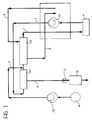
- Figure 1 shows the general structure of the hydraulic circuit of a dialysis machine operating according to the combined haemofiltration/haemodialysis principle.
- the blood which is taken from the patient P undergoing the treatment by a main circuit, generally indicated 1, is passed through a first peristaltic pump P1 which supplies it to a haemofilter HF and to a haemodialysis filter HD and is then re-admitted to the body of the patient P.
- the fraction (the ultrafiltrate) removed in the haemofilter is restored upstream of the haemodialysis filter HD by means of an infusion solution taken from a respective reservoir R by means of a further peristaltic pump P2 which supplies the infusion solution to a pipe 2 which admits the infusion solution to the haemodialysis filter HD downstream of the haemofilter HF.
- the two branches (intake and output) of the circuit which supplies the dialysis solution to the dialysis filter HD are indicated 3.
- a sensor 10 formed according to the invention, is connected in the line 4 and measures the concentration of urea in the ultrafiltrate coming from the haemofilter HF.
- a non-return valve 5 is preferably associated with the sensor 10 for preventing any of the ultrafiltrate from returning towards the haemofilter HF.
- the pumps P1 and P2 subservient to a control or monitoring system, shown schematically in the form of two modules M1, M2 which are interdependent (for example, as a result of a contact operation effected by a unit such as a microprocessor or other processing unit) so as to regulate the haemofiltration and haemodialysis processes according to the requirements of the treatment in progress.
- a control or monitoring system shown schematically in the form of two modules M1, M2 which are interdependent (for example, as a result of a contact operation effected by a unit such as a microprocessor or other processing unit) so as to regulate the haemofiltration and haemodialysis processes according to the requirements of the treatment in progress.
- the pump P1 regulates the flow-rate of the blood which is taken from and re-admitted to the patient in order to perform the purification treatment.
- the pump P2 is regulated so that the reinfusion solution taken from the reservoir R is restored in the desired manner to the ultrafiltrate mass picked up by the filter HF.
- control operations and other control and regulation operations are carried out in dependence on the various chemical/physical parameters which come into play during the treatment.
- one of these parameters is usually constituted by the urea concentration in the ultrafiltrate coming from the filter HF.
- a sensor such as the sensor 10 which can provide the concentration of urea in the ultrafiltrate in real time and on-line makes the control of the purification process particularly effective and precise.
- sensors operating on the same principle as the sensor 10 described below may be inserted in a system such as the system of Figure 1 in order to monitor other concentration parameters (for example, for monitoring the concentration of creatinine in the ultrafiltrate coming from the haemofilter HF).
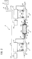
- the conductimetric probes 11 and 13 may be produced with the use of any solution known in the art for this purpose. However, it has been found particularly advantageous to use, within the scope of the invention, conductimetric probes such as those forming the subject of Italian patent application No. 3340-A/90. These conductimetric probes are produced by the company Tecnologie Dinamiche S.r.l., of Bologna (Italy).
- a probe of this type is constituted essentially by a main tube 20 through which the liquid sample, the conductivity of which is to be measured, flows.
- this pipe is divided into two parallel branches 20a, 20b which join together again at the output end of the probe (naturally, the direction of flow of the liquid sample through the probe is from left to right as shown by the arrows of Figure 2).
- Two electromagnetic coils 21, 22 are disposed fluidodynamically upstream and downstream of each other (naturally still with reference to the direction of flow of the liquid sample through the probe) on the branch 20a.
- the conductimetric measurement is derived from a determination of the degree of coupling (magnetic induction) established between the two coils 21 and 22 by means of the liquid undergoing measurement.
- the main sources of errors for measurements of this type are fluctuations in the temperature of the liquid field.
- the probes 11, 13 have thermistors 24 (or equivalent thermometric elements) which monitor the temperature of the liquid sample, preferably at the output ends of the probes 11, 13, and provide feedback to the control board 23 in order to put into effect a temperature compensation step.
- Each of the conductimetric probes 11, 13 has an associated voltage measuring sensor 23a which emits, on a respective output line 11a, 13a, a signal indicative of the conductivity value measured in the liquid sample flowing through the respective probe.
- the conductivity signals obtained are sent (possibly after conversion into digital form by means of converter circuits, not shown, which may, however, be incorporated in the probes themselves) to a differentiator element or, in general, to a module 14 which is sensitive to the variation between the conductivity values detected by the probes 11 and 13.
- the two conductivity values detected by the probes 11 and 13 may also be detected separately, the task of determining their variation being left to a subsequent processing step.
- the difference between the values mentioned above constitutes an indication of the concentration of the substance which is being determined (for example, urea) in the flow passing through the sensor 10.
- the difference signal for example, their ratio, or the difference standardized with respect to one of the conductivity values measured, etc.
- the signal coming from the module 14 which is sensitive to the variation between the two conductivity values measured by the probes 11, 13 can be transmitted to a unit 15 for presenting it externally, such as, for example, a display unit or a unit for recording it on a paper or informatics substrate.
- the reactor 12 in which the enzymatic conversion of the urea into ammonium carbonate salt is carried out is preferably configured in the form of a small column of, for example, plastics material with respective input and output lines for the liquid sample which passes through the reactor 12 (again from left to right with reference to Figure 2).
- filter elements 30a, 31a are associated with the connecting lines of the reactor - constituted by pipes 30 and 31 (for input and output respectively) - and are constituted, for example, by membranes of material known by the trade name Porex, the function of which is essentially to stop any particulates present in the ultrafiltrate upstream of the reaction zone and, correspondingly, to retain portions of enzyme separated from the substrate in the reaction zone - preventing their dispersal towards the ultrafiltrate output line.
- the substrate in question is constituted, as already stated, for example, by a material such as the material known by the trade name Eupergit C, generally indicated 32.
- the concentration value C can be derived on the basis of the monitoring of the change in conductivity ⁇ k (the variation between the measurements supplied by the two probes 11, 13).
- Screws, indicated 33 hold the end portions or plugs in which the connection lines 30, 32 are disposed, on the cylindrical body 34 of the reactor which contains the enzyme (urease in the case of urea determination) conjugated with the substrate particles 32.
- the enzyme urease in the case of urea determination
- sealing elements such as O-rings are normally inserted between the plugs and the cylindrical body.
- the following known method may be used to conjugate the urease enzyme with the particles of the Eupergit C substrate.
- the first step from 10 to 200 ml of enzyme are dissolved in 4 ml of 1M potassium phosphate buffer (pH-7.5, produced by mixing 23 ml of KH2PO4 with 77 ml of 1M K2HPO4 containing 500 ppm, that is 50 mg in 2 ml of isopropanol, ethyl diester of p-hydroxybenzoic acid as an anti-microbial agent).
- 1M potassium phosphate buffer pH-7.5, produced by mixing 23 ml of KH2PO4 with 77 ml of 1M K2HPO4 containing 500 ppm, that is 50 mg in 2 ml of isopropanol, ethyl diester of p-hydroxybenzoic acid as an anti-microbial agent.
- the enzyme solution is then added to 1000 mg of Eupergit C in a wide-necked flask.
- the flask is very firmly closed and is then left at ambient temperature and without stirring for from 16 to 72 hours.
- the product (urease conjugated with Eupergit C) is to be kept at +5 o C after the transfer of the 0.1M phosphate buffer to which 1 mM EDTA and 1 mM reduced glutathione are added; the latter act as protectors against heavy metals.
- FIGS 3 to 7 show some experimental results which demonstrate the correct operation of the solution according to the invention.
- the graph of Figure 3 gives the variation (the difference) between the conductivity values measured in the urea solution before and after the total enzymatic conversion of the urea into the ammonium salt (NH4)2CO3, as a function of the concentration (in mM) in a vector fluid constituted by a 50 mM glycine buffer + 0.9% NaCl.
- the curve which represents the conductivity variation is the continuous line connecting the dots in the graph.
- the other graph (constituted by a broken line connecting small triangles) constitutes the conductivity value detected (for the same concentration values) in a solution of the ammonium salt in the same vector.
- the graph of Figure 4 is intended to show the wholly deterministic character and the degree of absolute repeatability of the measurement method according to the invention.
- This graph shows the conductivity values (in mS/cm) as a function of time obtained by carrying out a complete dialysis of bovine blood to which a quantity of urea equal to 50 mmoles/l had been added with the subsequent addition after 80 min. of a second mass (bolus) of urea, again equal to 50 mmoles/l.
- the two conductivity curves have exactly the same time trace.
- Figure 5 reproduces the first part of the graph of Figure 4 with the ordinate scale changed to a logarithmic scale.
- the graph of Figure 5 shows the exponential behaviour of the urea concentration with respect to time and its linearization gives rise to a straight line with a correlation coefficient of 0.999.
- the graphs of Figures 6 and 7 relate to tests to determine the concentration of urea in blood ( Figure 6) and in ultrafiltrate ( Figure 7).
- the abscissa scale gives the data of the concentration detected by a sensor according to the invention
- the ordinate scale gives the concentration values measured by reference methods (of a photometric nature) currently used in clinical laboratories.
- the correlation coefficients found are 0.993 and 0.997 for the data relating to blood and to ultrafiltrate, respectively.
- the method according to the invention thus enables a determination (measurement) to be carried out on-line, in real time, obtaining measurement values which are generally much more precise and reliable than the values obtainable by conventional methods which, above all, do not permit operation on-line and/or in real time.
Landscapes
- Health & Medical Sciences (AREA)
- Life Sciences & Earth Sciences (AREA)
- Heart & Thoracic Surgery (AREA)
- Chemical & Material Sciences (AREA)
- General Health & Medical Sciences (AREA)
- Immunology (AREA)
- Engineering & Computer Science (AREA)
- Biochemistry (AREA)
- Physics & Mathematics (AREA)
- General Physics & Mathematics (AREA)
- Electrochemistry (AREA)
- Pathology (AREA)
- Chemical Kinetics & Catalysis (AREA)
- Vascular Medicine (AREA)
- Analytical Chemistry (AREA)
- Anesthesiology (AREA)
- Biomedical Technology (AREA)
- Hematology (AREA)
- Animal Behavior & Ethology (AREA)
- Public Health (AREA)
- Veterinary Medicine (AREA)
- Investigating Or Analyzing Materials By The Use Of Electric Means (AREA)
- Investigating Or Analysing Biological Materials (AREA)
Abstract
Description
- The present invention relates in general to the measurement of the concentration of a substance in a fluid.
- The invention has been developed with particular attention to its possible use for determining the concentration of urea in biological fluids, for example, in dialysis equipment.
- As will be explained further below, the invention is not limited to this possible use but is applicable, in general, to the measurement of the concentration in a fluid of any substance which can be converted into conversion products so as to bring about a change in the conductivity (the electrical conductivity) of the fluid carrying the substance.
- In order to calculate the concentration of a substance in a fluid, possibly in the form of a continuous flow, it is generally known to correlate the variation of a certain parameter detectable by the measurement device, which differs from one case to another, with the variation in the concentration of the substance in the fluid under examination.
- For example, known biosensors for determining urea concentration are based on the application of the potentiometric method, with electrodes having ion-selective membranes or with electrodes having gas-permeable membranes, or on the application of the thermometric method, on the application of the conductimetric method, or even on the application of the spectrophotometric method.
- The relevant literature is quite extensive.
- By way of reference, the following articles may be mentioned, for example:
- "An enzyme electrode for the substrate urea" by G.G. Guilbault and J.G. Montalvo, which appeared in the "Journal of the American Chemical Society", Vol. 92, No. 8, April 1970;
- "Urea coupled ammonia electrode for urease determination in blood serum" by M. Mascini and G.G. Guilbault, which appeared in "Analytical Chemistry", Vol. 49, No. 6, May 1977;
- "Enzyme urea biosensor based on a modified potentiometric pvc-nonactin membrane electrode for assay of urea in blood" by S.B. Butt and K. Camman, which appeared in "Analytical letters", Vol. 25, No. 9, September 1992;
- "Determination of urea with an ammonia gas-sensitive semiconductor device in combination with urease" by F. Winquist, A. Spetz and I. Lundström, which appeared in Analytica Chimica Acta 163, 1981; and
- Guilbault and Montalvo described, in the article mentioned, a biosensor for urea prepared by immobilizing the urease enzyme in a polyacrylamide matrix on a nylon net. The net was then arranged on an ion-selective electrode responding to the ammonium ion. This biosensor (even in the subsequently perfected and improved versions) has various problems which limit its possible uses, particularly when it is to be used on-line on a dialysis machine.
- In the first place, in fact, it requires a preliminary calibration of the biosensor with a known solution and concentration and various periodic calibrations to prevent the problem of the drift of the response over time; this inevitably increases the operations necessary on the part of the operator, whereas the tendency is to limit such operations as much as possible.
- Moreover, this type of sensor necessitates slow flows: the main flow line of the liquid analyzed therefore has to be bypassed and an auxiliary pump used, consequently increasing costs.
- Furthermore, these sensors have an intrinsic limitation, that is, they have poor selectivity for ammonium ions in the presence of potassium and sodium ions.
- As can be seen from the article by Butt and Camman, this latter problem can be avoided with the use of a urea biosensor with a gas-permeable membrane which is sensitive, in the specific case, to ammonia. However, in addition to the fact that it does not solve the problems relating to calibration and flow, the electrode with a gas-permeable membrane has the disadvantage that it has slow response times and a slow return to the base line.
- Other sensors provide for the use of MOS (metal-oxide semiconductor) devices such as, for example, those described by Winquist et al.. The MOS devices used in these sensors are capacitors the capacitance-voltage characteristics of which vary in dependence on the concentration of ammonia adsorbed on the surface of the metal. The ammonia detected is the reaction product of the enzymatic hydrolysis of urea by means of urease or of the hydrolysis of creatinine by means of creatinase (in which a 100% conversion of the substrate is assumed). A disadvantage of these sensors is represented by the interference of amines with low molecular weights and of hydrogen. The problems relating to calibration, to small sample volumes and to the need for auxiliary accessories (pump, valve, stock of buffer), however, remain.
- As regards the use of the thermometric method, the article "Determination of serum urea with an enzyme thermistor using immobilized urease" by B. Danielsson, K. Gadd, B. Mattiasson and K. Mosbach, which appeared in "Analytical letters", Vol. 9, No. 11, 1976, may be mentioned.
- The thermometric biosensor described by Danielsson et al. measures the heat produced when urea passes through a column containing immobilized urease enzyme ; it has a wide measurement range and the linearity extends almost up to 200 mmol/l. This sensor operates with very slow flows and the sample is introduced in pulses by means of a three-way valve. The problems with this sensor are its high degree of sensitivity to flow variations, the long waiting time until a stable base line is obtained, and the need for calibration.
- Examples of the use of the conductimetric method are provided by the articles "Conductivity method for determination of urea" by W.T. Chin and W. Kroontye, which appeared in "Analytical Chemistry", Vol. 33, No. 12, November 1961; "Application de la conductimetrie à l'étude des reactions enzymatiques - Système urée -uréase" (Application of conductimetry to the study of enzymatic reactions - the urea-urease system) by M. Hanss and A. Rey, which appeared in "Biochimica" and "Biophysica Acta" No. 227, 1971; "Conductimetric enzyme assay" by A.J. Lawrence, which appeared in "European Journal of Biochemistry", Vol. 18, No. 2, 1971; "Conductimetry in enzyme studies" by A.J. Lawrence and G.R. Moores, which appeared in "European Journal of Biochemistry", Vol. 24, No. 3, 1972; the article "A micro-electronic conductimetric biosensor" by D. Watson, P. Maynard, D.C. Cullen, R.S. Sephi, J. Breetle and C.R. Lowe, which appeard in "Biosensors", Vol. 3, No. 2, 1987/88; or the article "Continuous monitoring of urea in blood during dialysis" by P. Thavarungkul, H. Hakanson, O. Holst and B. Mattiasson, which appeared in "Biosensors & Bioelectronics", Vol. 6, 1991.
- Lowe and his group developed a microelectronic conductimetric bio-sensor with a two-sensor configuration (one with and one without urease enzyme) which has a good correlation with the spectro-photometric reference method; it has a rather narrow measurement range, however, and requires the sample to be diluted with a buffer before measurement.
- Another biosensor based on the conductimetric method has been developed by Mattiasson et al.. The system provides for the use of a sampling unit in combination with a conductimetric biosensor and also provides for an on-line arrangement for detecting the urea values during dialysis. Calibration with urea solutions of known concentration is required for this sensor. The whole system is quite complex. In fact it requires: a sampling unit, a blood heparinization line, an injector for the calibration or dialysis solution, a line for the dialysis buffer, the column with the immobilized enzyme, the conductivity monitoring cell. Since this cell is constituted by electrodes which are in direct contact with the dialysis liquid, however, it is subject to errors due to the adsorption of organic molecules and therefore requires frequent cleaning and calibration.
- It is consequently of very great interest to develop a biosensor for the continuous determination of urea (and, in general, of other substances carried by a fluid) which can be integrated in equipment (such as a dialysis machine) with the ability to achieve on-line detection in real time.
- For example, if reference is to be made (as will be done extensively below) to use in dialysis, this interest arises from the fact that the urea concentration, which is raised above the norm in a patient affected by kidney disease, decreases over time during dialysis and the dialysis may be defined as complete when the urea concentration values have been lowered so as to fall within the normal range. It is therefore very important to be aware of the progress of the urea concentration values in real time during the dialysis and to know that the value has returned within the norm at the actual moment when this occurs. This is in order to avoid a session being unnecessarily prolonged, the duration of the dialysis being determined, at the moment, on the basis of indirect data and being left to the discretion of the operator. Moreover, the dialysis patient may experience his condition in a less traumatic manner since he spends less time in specialized centres for each session.
- The object of the present invention is therefore to respond to the interest expressed above and to do this - it is underlined once more - not with reference to the determination of urea alone but, as regards the determination of the concentration of a substance in a fluid, particularly in a flow, in general. According to the present invention, this object is achieved by virtue of a method having the characteristics recited in the claims which follow. The invention also relates to a system for carrying out the method and to the use of the method for determining the concentrations of substances in fluids in equipment for purifying biological fluids such as, for example, blood.
- In summary, in a typical embodiment, the present invention provides for the formation of a differential conductimetric circuit which is connected "on-line" in a flow line (which may be either a main flow line or, possibly, a branch or bypass flow line which, there appropriate, is activated selectively solely during the time intervals in which the monitoring is to be carried out) in which a fluid flow carries a substance the concentration of which is to be determined.
- For example, the fluid in question may (as will be seen further below) be a liquid ultrafiltered within a dialysis process, in which the urea concentration is to be monitored.
- In general terms, the present invention is based on the possibility of carrying out a total conversion of the substance the concentration of which is to be monitored into conversion products so as to bring about a change in the electrical conductivity of the fluid containing the conversion products.
- Thus, if the electrical conductivity of the fluid containing the substance is measured before the conversion, so as to obtain a first electrical conductivity value, and the electrical conductivity of the fluid containing the products of the total conversion of the substance is then measured, so as to obtain a second conductivity value, it can be observed that the variation (typically the difference) between the electrical conductivity values determined before and after the total conversion is determined solely by the concentration of the substance in the fluid.
- For example, in the case of the determination of urea carried out in an at least partially aqueous vector, it is possible to use a total enzymatic conversion by passing the fluid through a small column which is packed with excess urease, so as to convert all of the urea present in the sample into ions according to the reaction:

It can readily be seen that the electrical conductivity measurement carried out downstream of the total conversion reaction enables the base conductivity plus the conductivity due to the ions formed as a result of the conversion (hydrolysis in the present case) of the urea to be determined. - Naturally, in order to use this technique for measuring concentrations there must be a linear correlation between the conductivity measured and the concentration, at least in the measurement range. The basic relationship is as follows:

in which K is the conductivity, C is the concentration, and Λ is a proportionality constant known as the equivalent conductance. - Λ may be evaluated by the direct measurement of the difference in the conductivity of the solution after complete enzymatic hydrolysis of a known quantity of urea. That is:

An alternative method for evaluating Λ consists of considering the hydrolysis products of urea: these are none other than the ions which make up the salt ammonium carbonate. It is thus possible to obtain Λ directly by measuring the conductivity of ammonium carbonate solutions of known concentration. - As already stated, the principle described above with specific reference to a total enzymatic conversion of urea is suitable for use for determining the concentration of substances other than urea.
- In general, in order to implement the invention, it is sufficient to be able to achieve a total enzymatic conversion of the substance of which the concentration is to be determined, into conversion products, so as to bring about a change in the electrical conductivity of the fluid carrying the substance. The desired concentration value can be derived by detecting the variation between the conductivity values determined before and after the conversion reaction.
- In general, therefore, the solution according to the invention is suitable for use for the real-time and on-line measurement of the concentration of any substance for which it is possible to carry out a total enzymatic conversion by means of one or more corresponding enzymes.
- By way of non-limiting example, the following conversion reactions may be mentioned:

On the basis of the tests carried out by the Applicant, the enzymatic reaction was found particularly advantageous with regard to the fact that total conversion can be achieved extremely quickly (and hence so as to be able to provide a response in real time and on-line) within a reactor of simple structure and small dimensions and of correspondingly low cost. - The invention will now be described by way of non-limiting example with reference to the appended drawings, in which:
- Figure 1 shows, in general, the hydraulic circuit of a haemodialysis system in which at least one sensor operating according to the invention may advantageously be incorporated,
- Figure 2 shows the structure of parts of the sensor according to the invention in greater detail, and
- Figures 3 to 7 are graphs showing results of the urea concentration measurements carried out according to the invention.
- As indicated, Figure 1 shows the general structure of the hydraulic circuit of a dialysis machine operating according to the combined haemofiltration/haemodialysis principle.
- The blood, which is taken from the patient P undergoing the treatment by a main circuit, generally indicated 1, is passed through a first peristaltic pump P1 which supplies it to a haemofilter HF and to a haemodialysis filter HD and is then re-admitted to the body of the patient P.
- The fraction (the ultrafiltrate) removed in the haemofilter is restored upstream of the haemodialysis filter HD by means of an infusion solution taken from a respective reservoir R by means of a further peristaltic pump P2 which supplies the infusion solution to a
pipe 2 which admits the infusion solution to the haemodialysis filter HD downstream of the haemofilter HF. - The two branches (intake and output) of the circuit which supplies the dialysis solution to the dialysis filter HD are indicated 3.
- Finally, the line for discharging the ultrafiltrate from the haemofilter HF is indicated 4. A
sensor 10, formed according to the invention, is connected in theline 4 and measures the concentration of urea in the ultrafiltrate coming from the haemofilter HF. - A
non-return valve 5 is preferably associated with thesensor 10 for preventing any of the ultrafiltrate from returning towards the haemofilter HF. - In particular, it is known to make the pumps P1 and P2 subservient to a control or monitoring system, shown schematically in the form of two modules M1, M2 which are interdependent (for example, as a result of a contact operation effected by a unit such as a microprocessor or other processing unit) so as to regulate the haemofiltration and haemodialysis processes according to the requirements of the treatment in progress.
- In general, the pump P1 regulates the flow-rate of the blood which is taken from and re-admitted to the patient in order to perform the purification treatment.
- The pump P2 is regulated so that the reinfusion solution taken from the reservoir R is restored in the desired manner to the ultrafiltrate mass picked up by the filter HF.
- The aforesaid control operations and other control and regulation operations are carried out in dependence on the various chemical/physical parameters which come into play during the treatment. In particular, one of these parameters is usually constituted by the urea concentration in the ultrafiltrate coming from the filter HF.
- The availability of a sensor such as the
sensor 10 which can provide the concentration of urea in the ultrafiltrate in real time and on-line makes the control of the purification process particularly effective and precise. - Naturally, sensors operating on the same principle as the
sensor 10 described below may be inserted in a system such as the system of Figure 1 in order to monitor other concentration parameters (for example, for monitoring the concentration of creatinine in the ultrafiltrate coming from the haemofilter HF). - In this connection, it should be noted that - in order to monitor the concentration effectively, it is not in fact necessary for the whole of the flow containing the substance the concentration of which is to be monitored to pass through the sensor such as the
sensor 10, as shown schematically in Figure 1. - In fact, it is possible to consider drawing off only a portion of the flow in which the concentration is to be monitored and passing through the sensor only that portion of the flow which has been drawn off. This possibility may also advantageously be used when it is desired to monitor the concentrations of two or more different substances in the same flow. For this purpose, for example, a corresponding number of branch flows may be drawn off from the main flow, and each may be passed through a respective sensor. Where appropriate, this may take place at different times and thus by drawing off a single branch flow and sending the flow to sensors of different types during successive time intervals. It is also possible to consider the positioning of several sensors fluidodynamically in series or in cascade, each sensor monitoring the concentration of a respective substance. Naturally, in order to be able to adopt this cascade arrangement, the total conversion carried out in each sensor must not affect the conversion mechanisms carried out in the other sensors situated downstream.
- To proceed with a detailed examination of the structure of the sensor 10 (Figure 2), it can be noted that it is constituted essentially by three elements disposed in cascade in the direction of flow of the ultrafiltrate (from left to right in Figure 2) through the
sensor 10, that is: - a first conductimetric sensor or
probe 11, - a
conversion reactor 12 constituted, for example, by a small column of plastics material packed with an enzyme, such as urease (in the case of urea determination), previously bonded covalently to a substrate material such as, for example, particles of the material known by the trade name Eupergit C, and - a further conductimetric sensor or
probe 13. - The conductimetric probes 11 and 13 may be produced with the use of any solution known in the art for this purpose. However, it has been found particularly advantageous to use, within the scope of the invention, conductimetric probes such as those forming the subject of Italian patent application No. 3340-A/90. These conductimetric probes are produced by the company Tecnologie Dinamiche S.r.l., of Bologna (Italy).
- By way of summary, it may be noted that a probe of this type is constituted essentially by a
main tube 20 through which the liquid sample, the conductivity of which is to be measured, flows. In the probe, this pipe is divided into twoparallel branches 20a, 20b which join together again at the output end of the probe (naturally, the direction of flow of the liquid sample through the probe is from left to right as shown by the arrows of Figure 2). - Two
electromagnetic coils coils probes probes control board 23 in order to put into effect a temperature compensation step. - Each of the
conductimetric probes voltage measuring sensor 23a which emits, on arespective output line 11a, 13a, a signal indicative of the conductivity value measured in the liquid sample flowing through the respective probe. The conductivity signals obtained are sent (possibly after conversion into digital form by means of converter circuits, not shown, which may, however, be incorporated in the probes themselves) to a differentiator element or, in general, to amodule 14 which is sensitive to the variation between the conductivity values detected by theprobes probes - As already stated (see the portion of the present description headed "Theoretical basis of the invention"), the difference between the values mentioned above constitutes an indication of the concentration of the substance which is being determined (for example, urea) in the flow passing through the
sensor 10. Naturally, however, it is possible to consider the use of any other signal indicative of the variation between the two conductivity values (for example, their ratio, or the difference standardized with respect to one of the conductivity values measured, etc.) instead of the difference signal. - In any case, the signal coming from the
module 14 which is sensitive to the variation between the two conductivity values measured by theprobes unit 15 for presenting it externally, such as, for example, a display unit or a unit for recording it on a paper or informatics substrate. - The
reactor 12 in which the enzymatic conversion of the urea into ammonium carbonate salt is carried out (according to the criteria recited extensively above), is preferably configured in the form of a small column of, for example, plastics material with respective input and output lines for the liquid sample which passes through the reactor 12 (again from left to right with reference to Figure 2). - Preferably,
filter elements 30a, 31a are associated with the connecting lines of the reactor - constituted bypipes 30 and 31 (for input and output respectively) - and are constituted, for example, by membranes of material known by the trade name Porex, the function of which is essentially to stop any particulates present in the ultrafiltrate upstream of the reaction zone and, correspondingly, to retain portions of enzyme separated from the substrate in the reaction zone - preventing their dispersal towards the ultrafiltrate output line. The substrate in question is constituted, as already stated, for example, by a material such as the material known by the trade name Eupergit C, generally indicated 32. - As stated above (see
formula 2 in the portion of the present description dedicated to the theoretical basis of the invention), by means of a knowledge of the proportionality constant Λ known as the equivalent conductance, the concentration value C can be derived on the basis of the monitoring of the change in conductivity Δk (the variation between the measurements supplied by the twoprobes 11, 13). - Screws, indicated 33, hold the end portions or plugs in which the connection lines 30, 32 are disposed, on the
cylindrical body 34 of the reactor which contains the enzyme (urease in the case of urea determination) conjugated with thesubstrate particles 32. Naturally, sealing elements such as O-rings are normally inserted between the plugs and the cylindrical body. - The following known method may be used to conjugate the urease enzyme with the particles of the Eupergit C substrate.
- As the first step, from 10 to 200 ml of enzyme are dissolved in 4 ml of 1M potassium phosphate buffer (pH-7.5, produced by mixing 23 ml of KH₂PO₄ with 77 ml of 1M K₂HPO₄ containing 500 ppm, that is 50 mg in 2 ml of isopropanol, ethyl diester of p-hydroxybenzoic acid as an anti-microbial agent).
- The enzyme solution is then added to 1000 mg of Eupergit C in a wide-necked flask. The flask is very firmly closed and is then left at ambient temperature and without stirring for from 16 to 72 hours.
- The mixture is then washed on a glass filter (porosity 2-5) with the use of a 0.1M potassium phosphate buffer (pH = 7.5) produced by mixing 170 ml of 0.1M KH₂PO₄ with 830 ml of K₂HPO₄ + 500 ppm of the ethyl ester of p-hydroxybenzoic acid. The product (urease conjugated with Eupergit C) is to be kept at +5oC after the transfer of the 0.1M phosphate buffer to which 1 mM EDTA and 1 mM reduced glutathione are added; the latter act as protectors against heavy metals.
- Figures 3 to 7 show some experimental results which demonstrate the correct operation of the solution according to the invention.
- In particular, the graph of Figure 3 gives the variation (the difference) between the conductivity values measured in the urea solution before and after the total enzymatic conversion of the urea into the ammonium salt (NH₄)₂CO₃, as a function of the concentration (in mM) in a vector fluid constituted by a 50 mM glycine buffer + 0.9% NaCl. The curve which represents the conductivity variation is the continuous line connecting the dots in the graph.
- The other graph (constituted by a broken line connecting small triangles) constitutes the conductivity value detected (for the same concentration values) in a solution of the ammonium salt in the same vector.
- It can be noted that the correlation between the two curves is very close (below the measurement tolerances) and demonstrates the importance of total and not only partial conversion, for the purposes of correct concentration measurement.
- The factor which makes the concentration measurement method of the invention independent of any calibration operation actually lies in the complete nature of the conversion; calibration is or would be necessary, however, in methods which do not provide for total conversion but only for partial conversion with the consequent need - in finding the concentration value from the variation between the conductivity values detected before and after the conversion - for the degree of conversion (which factor depends on numerous parameters of the process).
- The graph of Figure 4 is intended to show the wholly deterministic character and the degree of absolute repeatability of the measurement method according to the invention.
- This graph shows the conductivity values (in mS/cm) as a function of time obtained by carrying out a complete dialysis of bovine blood to which a quantity of urea equal to 50 mmoles/l had been added with the subsequent addition after 80 min. of a second mass (bolus) of urea, again equal to 50 mmoles/l. As can be seen, the two conductivity curves have exactly the same time trace.
- Figure 5 reproduces the first part of the graph of Figure 4 with the ordinate scale changed to a logarithmic scale. The graph of Figure 5 shows the exponential behaviour of the urea concentration with respect to time and its linearization gives rise to a straight line with a correlation coefficient of 0.999.
- Finally, the graphs of Figures 6 and 7 relate to tests to determine the concentration of urea in blood (Figure 6) and in ultrafiltrate (Figure 7). In particular, in both of the graphs, the abscissa scale gives the data of the concentration detected by a sensor according to the invention, and the ordinate scale gives the concentration values measured by reference methods (of a photometric nature) currently used in clinical laboratories. The correlation coefficients found are 0.993 and 0.997 for the data relating to blood and to ultrafiltrate, respectively.
- There is, however, reason to believe that the deviations in the correlations are to be attributed mainly to inaccuracies in the conventional monitoring methods.
- The method according to the invention thus enables a determination (measurement) to be carried out on-line, in real time, obtaining measurement values which are generally much more precise and reliable than the values obtainable by conventional methods which, above all, do not permit operation on-line and/or in real time.
- Naturally, the principle of the invention remaining the same, the details of construction and forms of embodiment may be varied widely with respect to those described and illustrated, without thereby departing from the scope of the present invention.
Claims (26)
- A method of determining the concentration of a substance in a fluid, characterized in that it comprises the steps of:- determining (11) the electrical conductivity of the fluid containing the substance, obtaining a first conductivity value (11a),- subjecting the substance in the fluid to total enzymatic conversion into conversion products so as to bring about a change in the electrical conductivity of the fluid containing the conversion products,- determining (13) the electrical conductivity of the fluid containing the conversion products, obtaining a second conductivity value (13a), and- detecting (14, 15) the variation between the first (11a) and second (13a) electrical conductivity values, the variation being indicative of the concentration (C) of the substance in the fluid.
- A method according to Claim 1, characterized in that the variation is detected as the difference between the first (11a) and second (13a) electrical conductivity values.
- A method according to Claim 1 or Claim 2, characterized in that it comprises the step of directing the fluid containing the substance into a flow, and in that the determination (11) of the electrical conductivity of the fluid containing the substance, the total enzymatic conversion (12) of the substance in the fluid into the conversion products, and the determination (13) of the electrical conductivity of the fluid containing the conversion products are carried out on the flow in cascade.
- A method according to any one of the preceding claims, characterized in that it comprises the step of directing the fluid containing the substance into a flow and the step of taking at least one branch flow from the flow, and in that the concentration of the substance is determined by operating on the branch flow.
- A method according to any one of the preceding claims, characterized in that the substance is selected from the group constituted by urea, creatinine, glucose, barbiturate, L-arginine, penicillin and acetylcholine.
- A method according to Claim 1, characterized in that the total enzymatic conversion is carried out with the use of at least one enzyme corresponding to the substance the concentration of which is to be determined.
- A method according to Claim 6, characterized in that the total enzymatic conversion is carried out with the use of a plurality of enzymes.
- A method according to Claim 6, characterized in that the substance is urea and the at least one enzyme is urease.
- A method according to Claim 7, characterized in that the substance is creatinine, and in that the plurality of enzymes comprises creatinine amidohydrolase, creatine amidohydrolase, and urease.
- A method according to Claim 6, characterized in that the substance is glucose, and in that the at least one enzyme is glucose oxidase.
- A method according to Claim 7, characterized in that the substance is barbiturate and the plurality of enzymes comprises barbiturase and urease.
- A method according to Claim 7, characterized in that the substance is L-arginine and the plurality of enzymes comprises arginase and urease.
- A method according to Claim 6, characterized in that the substance is penicillin and the at least one enzyme is penicillinase.
- A method according to Claim 6, characterized in that the substance is acetylcholine and the at least one enzyme is acetylcholinesterase.
- A method according to Claim 7, characterized in that the plurality of enzymes comprises urease.
- A method according to Claim 1, characterized in that the total enzymatic conversion is carried out with the use of at least one enzyme bonded covalently to a respective substrate (32).
- A method according to Claim 16, characterized in that the substrate (32) is constituted by particles of Eupergit C.
- A method according to any one of the preceding claims, characterized in that the first (11) and second (13) conductivity values are detected by determining the degree of coupling or magnetic induction between two coils (21, 22) through which the flow passes.
- A system for carrying out the method according to any one of the preceding claims, characterized in that it comprises at least one flow line (20, 31, 31) through which the fluid is intended to pass and in which there are interposed in cascade- first conductimetric means (11) for determining the electrical conductivity of the fluid containing the substance in order to obtain the first conductivity value (11a),- an enzymatic reactor (12) for subjecting the substance in the fluid to total enzymatic conversion into conversion products so as to bring about the change in the electrical conductivity of the fluid containing the conversion products,- second conductimetric means (13) for determining the electrical conductivity of the fluid containing the conversion products in order to obtain the second conductivity value (13a), and- detector means (14, 15) for detecting the variation between the first (11a) and the second (13a) electrical conductivity values, the variation being indicative of the concentration (C) of the substance in the fluid.
- A system according to Claim 19, characterized in that the detector means (14) detect the variation as the difference between the first (11a) and second (13a) electrical conductivity values.
- A system according to Claim 19 or Claim 20, characterized in that the enzymatic reactor (12) contains at least one enzyme bonded covalently to a respective substrate (32).
- A system according to Claim 21, characterized in that the substrate (32) is constituted by particles of Eupergit C.
- A system according to any one of the preceding Claims 19 to 22, characterized in that each of the first (11) and second (12) conductimetric means comprises:- a first electrical coil (21) interposed in the flow line,- a second electrical coil (22) interposed in the flow line, and- means (23, 23a) which are sensitive to the coupling or magnetic induction between the first coil (21) and the second coil (22).
- The use of the method according to any one of Claims 1 to 18 for determining the concentration of at least one substance in a respective fluid within equipment for purifying at least one biological fluid.
- Use according to Claim 24, in which the at least one biological fluid is blood.
- Use according to Claim 24 or Claim 25, in which the respective fluid is ultrafiltrate derived from a haemofiltration process.
Applications Claiming Priority (2)
| Application Number | Priority Date | Filing Date | Title |
|---|---|---|---|
| ITTO930145 | 1993-03-01 | ||
| ITTO930145A IT1260614B (en) | 1993-03-01 | 1993-03-01 | PROCEDURE FOR MEASURING THE CONCENTRATION OF A SUBSTANCE IN A FLUID, ITS SYSTEM AND USE |
Publications (2)
| Publication Number | Publication Date |
|---|---|
| EP0614081A1 true EP0614081A1 (en) | 1994-09-07 |
| EP0614081B1 EP0614081B1 (en) | 2000-07-12 |
Family
ID=11411212
Family Applications (1)
| Application Number | Title | Priority Date | Filing Date |
|---|---|---|---|
| EP93116848A Expired - Lifetime EP0614081B1 (en) | 1993-03-01 | 1993-10-19 | A method and a system for measuring the concentration of a substance in a fluid, and the use thereof |
Country Status (4)
| Country | Link |
|---|---|
| EP (1) | EP0614081B1 (en) |
| DE (1) | DE69329015T2 (en) |
| ES (1) | ES2149797T3 (en) |
| IT (1) | IT1260614B (en) |
Cited By (19)
| Publication number | Priority date | Publication date | Assignee | Title |
|---|---|---|---|---|
| EP1338891A1 (en) * | 2002-02-22 | 2003-08-27 | Toyo Engineering Corporation | Method and apparatus for determining urea concentration |
| CN102445476A (en) * | 2010-09-28 | 2012-05-09 | 恩德莱斯和豪瑟尔测量及调节技术分析仪表两合公司 | Method for operating a measuring device having at least one probe, which has at least one ion selective electrode |
| US9623164B2 (en) | 2013-02-01 | 2017-04-18 | Medtronic, Inc. | Systems and methods for multifunctional volumetric fluid control |
| US9713666B2 (en) | 2013-01-09 | 2017-07-25 | Medtronic, Inc. | Recirculating dialysate fluid circuit for blood measurement |
| CN107085117A (en) * | 2015-10-09 | 2017-08-22 | 恩德莱斯和豪瑟尔分析仪表两合公司 | Measurement apparatus |
| EP2145091B1 (en) * | 2007-05-08 | 2017-12-06 | Schrader Electronics Limited | Liquid level and composition sensing systems and methods |
| CN107699481A (en) * | 2017-09-26 | 2018-02-16 | 河海大学 | A device and method for measuring the activity of urea hydrolysis bacteria in the whole process of microbial solidification experiment |
| US10010663B2 (en) | 2013-02-01 | 2018-07-03 | Medtronic, Inc. | Fluid circuit for delivery of renal replacement therapies |
| US10478545B2 (en) | 2013-11-26 | 2019-11-19 | Medtronic, Inc. | Parallel modules for in-line recharging of sorbents using alternate duty cycles |
| US10695481B2 (en) | 2011-08-02 | 2020-06-30 | Medtronic, Inc. | Hemodialysis system having a flow path with a controlled compliant volume |
| US10850016B2 (en) | 2013-02-01 | 2020-12-01 | Medtronic, Inc. | Modular fluid therapy system having jumpered flow paths and systems and methods for cleaning and disinfection |
| US10926017B2 (en) | 2014-06-24 | 2021-02-23 | Medtronic, Inc. | Modular dialysate regeneration assembly |
| US10981148B2 (en) | 2016-11-29 | 2021-04-20 | Medtronic, Inc. | Zirconium oxide module conditioning |
| US11045790B2 (en) | 2014-06-24 | 2021-06-29 | Medtronic, Inc. | Stacked sorbent assembly |
| US11154648B2 (en) * | 2013-01-09 | 2021-10-26 | Medtronic, Inc. | Fluid circuits for sorbent cartridge with sensors |
| US11213616B2 (en) | 2018-08-24 | 2022-01-04 | Medtronic, Inc. | Recharge solution for zirconium phosphate |
| US11219880B2 (en) | 2013-11-26 | 2022-01-11 | Medtronic, Inc | System for precision recharging of sorbent materials using patient and session data |
| US12285552B2 (en) | 2018-08-14 | 2025-04-29 | Mozarc Medical Us Llc | Precision dialysis therapy based on sorbent effluent analysis |
| US12397093B2 (en) | 2021-05-18 | 2025-08-26 | Mozarc Medical Us Llc | Sorbent cartridge designs |
Families Citing this family (5)
| Publication number | Priority date | Publication date | Assignee | Title |
|---|---|---|---|---|
| US11565029B2 (en) | 2013-01-09 | 2023-01-31 | Medtronic, Inc. | Sorbent cartridge with electrodes |
| US9707328B2 (en) | 2013-01-09 | 2017-07-18 | Medtronic, Inc. | Sorbent cartridge to measure solute concentrations |
| US9144640B2 (en) | 2013-02-02 | 2015-09-29 | Medtronic, Inc. | Sorbent cartridge configurations for improved dialysate regeneration |
| US10960381B2 (en) | 2017-06-15 | 2021-03-30 | Medtronic, Inc. | Zirconium phosphate disinfection recharging and conditioning |
| US12569601B2 (en) | 2021-04-07 | 2026-03-10 | Mozarc Medical Us Llc | Increased operational capabilities of a dialysis system |
Citations (3)
| Publication number | Priority date | Publication date | Assignee | Title |
|---|---|---|---|---|
| US3839154A (en) * | 1973-08-20 | 1974-10-01 | Corning Glass Works | Apparatus and method for measuring conductivity change in a glucose-glucose oxidase reaction |
| JPS5774097A (en) * | 1980-10-27 | 1982-05-10 | Yokogawa Hokushin Electric Corp | Measurement of creatinine and device therefor |
| DE3900119C1 (en) * | 1989-01-04 | 1990-08-02 | Stiller, Siegfried, Dipl.-Phys., 5100 Aachen, De | Apparatus for measuring the urea concentration in an extracorporeal circulation |
-
1993
- 1993-03-01 IT ITTO930145A patent/IT1260614B/en active IP Right Grant
- 1993-10-19 EP EP93116848A patent/EP0614081B1/en not_active Expired - Lifetime
- 1993-10-19 ES ES93116848T patent/ES2149797T3/en not_active Expired - Lifetime
- 1993-10-19 DE DE69329015T patent/DE69329015T2/en not_active Expired - Fee Related
Patent Citations (3)
| Publication number | Priority date | Publication date | Assignee | Title |
|---|---|---|---|---|
| US3839154A (en) * | 1973-08-20 | 1974-10-01 | Corning Glass Works | Apparatus and method for measuring conductivity change in a glucose-glucose oxidase reaction |
| JPS5774097A (en) * | 1980-10-27 | 1982-05-10 | Yokogawa Hokushin Electric Corp | Measurement of creatinine and device therefor |
| DE3900119C1 (en) * | 1989-01-04 | 1990-08-02 | Stiller, Siegfried, Dipl.-Phys., 5100 Aachen, De | Apparatus for measuring the urea concentration in an extracorporeal circulation |
Non-Patent Citations (13)
| Title |
|---|
| " BY G.G. GUILBAULT; J.G. MONTALVO: "An enzyme electrode for the substrate urea", JOURNAL OF THE AMERICAN CHEMICAL SOCIETY, vol. 92, 8 April 1970 (1970-04-08) |
| A.J. LAWRENCE: "Conductimetric enzyme assay", EUROPEAN JOURNAL OF BIOCHEMISTRY, vol. 18, no. 2, 1971 |
| A.J. LAWRENCE; G.R. *MOORES: "Conductimetry in enzyme studies", EUROPEAN JOURNAL OF BIOCHEMISTRY, vol. 24, no. 3, 1972 |
| B. DANIELSSON ET AL.: "Determination of serum urea with an enzyme thermistor using immobilised urease", ANALYTICAL LETTERS, vol. 9, no. 11, 1976 |
| D. WATSON ET AL.: "A micro-electronic conductimetric biosensor", BIOSENSORS, vol. 3, no. 2, 1987 |
| DATABASE WPI Week 8224, Derwent World Patents Index; AN 8249137 * |
| F. WINQUIST; A. SPETZ; I. LUNDSTROM: "Determination of creatinine by an ammonia-sensitive semiconductor structure and immobilized enzymes", ANALYTICAL CHEMISTRY, vol. 58, 1986 |
| F. WINQUIST; A. SPETZ; I. LUNDSTROM: "Determination of urea with an ammonia gas-sensitive semiconductor device in combination with urease", ANALYTICA CHIMICA ACTA, 1981, pages 163 |
| M. HANSS; A. REY: "Application de la conductimetrie a 1'etude des reactions enzymatiques - Systeme ur6e -urease", "BIOCHIMICA" AND "BIOPHYSICA ACTA", no. 227, 1971 |
| M. MASCINI; G.G. GUILBAULT: "Urea coupled ammonia electrode for urease determination in blood serum", ANALYTICAL CHEMISTRY, vol. 49, no. 6, May 1977 (1977-05-01), XP001347598 |
| P. THAVARUNGKUL ET AL.: ""Continuous monitoring of urea in blood during dialysis", BIOSENSORS & BIOELECTRONICS, vol. 6, 1991 |
| S.B. BUTT; K. CAMMAN: "Enzyme urea biosensor based on a modified potentiometric pvc-nonactin membrane electrode for assay of urea in blood", ANALYTICAL LETTERS, vol. 25, no. 9, September 1992 (1992-09-01) |
| W.T. CHIN; W. KROONTYE: "Conductivity method for determination of urea", ANALYTICAL CHEMISTRY, vol. 33, no. 12, November 1961 (1961-11-01) |
Cited By (30)
| Publication number | Priority date | Publication date | Assignee | Title |
|---|---|---|---|---|
| US7153693B2 (en) | 2002-02-22 | 2006-12-26 | Toyo Engineering Corporation | Method and apparatus for determining urea concentration |
| EP1338891A1 (en) * | 2002-02-22 | 2003-08-27 | Toyo Engineering Corporation | Method and apparatus for determining urea concentration |
| EP2145091B1 (en) * | 2007-05-08 | 2017-12-06 | Schrader Electronics Limited | Liquid level and composition sensing systems and methods |
| CN102445476A (en) * | 2010-09-28 | 2012-05-09 | 恩德莱斯和豪瑟尔测量及调节技术分析仪表两合公司 | Method for operating a measuring device having at least one probe, which has at least one ion selective electrode |
| CN102445476B (en) * | 2010-09-28 | 2014-08-20 | 恩德莱斯和豪瑟尔测量及调节技术分析仪表两合公司 | Method for operating a measuring device having at least one probe, which has at least one ion selective electrode |
| US10695481B2 (en) | 2011-08-02 | 2020-06-30 | Medtronic, Inc. | Hemodialysis system having a flow path with a controlled compliant volume |
| US10881777B2 (en) | 2013-01-09 | 2021-01-05 | Medtronic, Inc. | Recirculating dialysate fluid circuit for blood measurement |
| US11154648B2 (en) * | 2013-01-09 | 2021-10-26 | Medtronic, Inc. | Fluid circuits for sorbent cartridge with sensors |
| US12161788B2 (en) * | 2013-01-09 | 2024-12-10 | Mozarc Medical Us Llc | Fluid circuits for sorbent cartridges with sensors |
| US9713666B2 (en) | 2013-01-09 | 2017-07-25 | Medtronic, Inc. | Recirculating dialysate fluid circuit for blood measurement |
| US11857712B2 (en) | 2013-01-09 | 2024-01-02 | Mozarc Medical Us Llc | Recirculating dialysate fluid circuit for measurement of blood solute species |
| US20210338912A1 (en) * | 2013-01-09 | 2021-11-04 | Medtronic, Inc. | Fluid circuits for sorbent cartridges with sensors |
| US10010663B2 (en) | 2013-02-01 | 2018-07-03 | Medtronic, Inc. | Fluid circuit for delivery of renal replacement therapies |
| US10850016B2 (en) | 2013-02-01 | 2020-12-01 | Medtronic, Inc. | Modular fluid therapy system having jumpered flow paths and systems and methods for cleaning and disinfection |
| US9623164B2 (en) | 2013-02-01 | 2017-04-18 | Medtronic, Inc. | Systems and methods for multifunctional volumetric fluid control |
| US10478545B2 (en) | 2013-11-26 | 2019-11-19 | Medtronic, Inc. | Parallel modules for in-line recharging of sorbents using alternate duty cycles |
| US10668202B2 (en) | 2013-11-26 | 2020-06-02 | Medtronic, Inc. | Parallel modules for in-line recharging of sorbents using alternate duty cycles |
| US11219880B2 (en) | 2013-11-26 | 2022-01-11 | Medtronic, Inc | System for precision recharging of sorbent materials using patient and session data |
| US11045790B2 (en) | 2014-06-24 | 2021-06-29 | Medtronic, Inc. | Stacked sorbent assembly |
| US11673118B2 (en) | 2014-06-24 | 2023-06-13 | Mozarc Medical Us Llc | Stacked sorbent assembly |
| US10926017B2 (en) | 2014-06-24 | 2021-02-23 | Medtronic, Inc. | Modular dialysate regeneration assembly |
| CN107085117A (en) * | 2015-10-09 | 2017-08-22 | 恩德莱斯和豪瑟尔分析仪表两合公司 | Measurement apparatus |
| US11703494B2 (en) | 2015-10-09 | 2023-07-18 | Endress+Hauser Conducta Gmbh+Co. Kg | Measuring device |
| US10981148B2 (en) | 2016-11-29 | 2021-04-20 | Medtronic, Inc. | Zirconium oxide module conditioning |
| US11642654B2 (en) | 2016-11-29 | 2023-05-09 | Medtronic, Inc | Zirconium oxide module conditioning |
| CN107699481B (en) * | 2017-09-26 | 2023-11-07 | 河海大学 | Device and method for measuring overall process activity of urea-hydrolyzing bacteria in microbial solidification experiment |
| CN107699481A (en) * | 2017-09-26 | 2018-02-16 | 河海大学 | A device and method for measuring the activity of urea hydrolysis bacteria in the whole process of microbial solidification experiment |
| US12285552B2 (en) | 2018-08-14 | 2025-04-29 | Mozarc Medical Us Llc | Precision dialysis therapy based on sorbent effluent analysis |
| US11213616B2 (en) | 2018-08-24 | 2022-01-04 | Medtronic, Inc. | Recharge solution for zirconium phosphate |
| US12397093B2 (en) | 2021-05-18 | 2025-08-26 | Mozarc Medical Us Llc | Sorbent cartridge designs |
Also Published As
| Publication number | Publication date |
|---|---|
| EP0614081B1 (en) | 2000-07-12 |
| ITTO930145A1 (en) | 1994-09-01 |
| ES2149797T3 (en) | 2000-11-16 |
| DE69329015D1 (en) | 2000-08-17 |
| IT1260614B (en) | 1996-04-22 |
| DE69329015T2 (en) | 2000-11-16 |
| ITTO930145A0 (en) | 1993-03-01 |
Similar Documents
| Publication | Publication Date | Title |
|---|---|---|
| EP0614081B1 (en) | A method and a system for measuring the concentration of a substance in a fluid, and the use thereof | |
| Xie et al. | Development of an integrated thermal biosensor for the simultaneous determination of multiple analytes | |
| US7002670B2 (en) | Optical sensor and method for measuring concentration of a chemical constituent using its intrinsic optical absorbance | |
| KR20010066848A (en) | Sample detection to initiate timing of an electrochemical assay | |
| Soldatkin et al. | Application of enzyme/zeolite sensor for urea analysis in serum | |
| US4153513A (en) | Method and apparatus for the continuous determination of the concentration of an enzyme substrate | |
| US4490235A (en) | Electrochemical cell provided with selective electrodes and at least one chemical reactor, for indirect measurement of clinical-chemical parameters | |
| Thavarungkul et al. | Continuous monitoring of urea in blood during dialysis | |
| Della Ciana et al. | Robust, reliable biosensor for continuous monitoring of urea during dialysis | |
| Jurkiewicz et al. | Development of a biparametric bioanalyser for creatinine and urea. Validation of the determination of biochemical parameters associated with hemodialysis | |
| Yasuda et al. | Determination of urea in whole blood using a urea electrode with an immobilised urease membrane | |
| US5976465A (en) | Apparatus and method for the determination of substances in solution suspension or emulsion by differential pH measurement | |
| Campanella et al. | Determination of choline-containing phospholipids in human bile and serum by a new enzyme sensor | |
| Petersson | Enzymatic determination of urea in undiluted whole blood by flow injection analysis using an ammonium ion-selective electrode | |
| US5516697A (en) | Biosensor for detecting iron | |
| US6287851B1 (en) | Sensor for analyzing components of fluids | |
| WO1994018559A1 (en) | Asymmetric membrane sensor | |
| Sundaram et al. | Immobilized-enzyme nylon-tube reactors for routine determination of urea and citrulline in serum. | |
| Andersen et al. | Analytical and economical optimization of a glucose method with immobilized enzymes | |
| JPS5916780B2 (en) | Artificial kidney monitor device | |
| Macheras et al. | An automated flow injection-serial dynamic dialysis technique for drug-protein binding studies | |
| Calzavara et al. | A new biosensor for continuous monitoring of the spent dialysate urea level in standard hemodialysis | |
| Matuszewski et al. | Elimination of interferences in flow‐injection amperometric determination of glucose in blood serum using immobilized glucose oxidase | |
| JPS6353502B2 (en) | ||
| Kyröläinen et al. | Biosensor monitoring of blood lactate during open-heart surgery |
Legal Events
| Date | Code | Title | Description |
|---|---|---|---|
| PUAI | Public reference made under article 153(3) epc to a published international application that has entered the european phase |
Free format text: ORIGINAL CODE: 0009012 |
|
| AK | Designated contracting states |
Kind code of ref document: A1 Designated state(s): DE ES FR GB IT NL SE |
|
| 17P | Request for examination filed |
Effective date: 19941228 |
|
| RAP1 | Party data changed (applicant data changed or rights of an application transferred) |
Owner name: BELLCO S.P.A. |
|
| 17Q | First examination report despatched |
Effective date: 19970130 |
|
| GRAG | Despatch of communication of intention to grant |
Free format text: ORIGINAL CODE: EPIDOS AGRA |
|
| GRAG | Despatch of communication of intention to grant |
Free format text: ORIGINAL CODE: EPIDOS AGRA |
|
| GRAH | Despatch of communication of intention to grant a patent |
Free format text: ORIGINAL CODE: EPIDOS IGRA |
|
| GRAH | Despatch of communication of intention to grant a patent |
Free format text: ORIGINAL CODE: EPIDOS IGRA |
|
| GRAA | (expected) grant |
Free format text: ORIGINAL CODE: 0009210 |
|
| RAP1 | Party data changed (applicant data changed or rights of an application transferred) |
Owner name: BELLCO S.P.A. |
|
| AK | Designated contracting states |
Kind code of ref document: B1 Designated state(s): DE ES FR GB IT NL SE |
|
| REF | Corresponds to: |
Ref document number: 69329015 Country of ref document: DE Date of ref document: 20000817 |
|
| ITF | It: translation for a ep patent filed | ||
| ET | Fr: translation filed | ||
| REG | Reference to a national code |
Ref country code: ES Ref legal event code: FG2A Ref document number: 2149797 Country of ref document: ES Kind code of ref document: T3 |
|
| PLBE | No opposition filed within time limit |
Free format text: ORIGINAL CODE: 0009261 |
|
| STAA | Information on the status of an ep patent application or granted ep patent |
Free format text: STATUS: NO OPPOSITION FILED WITHIN TIME LIMIT |
|
| 26N | No opposition filed | ||
| REG | Reference to a national code |
Ref country code: GB Ref legal event code: IF02 |
|
| PGFP | Annual fee paid to national office [announced via postgrant information from national office to epo] |
Ref country code: SE Payment date: 20020830 Year of fee payment: 10 |
|
| PGFP | Annual fee paid to national office [announced via postgrant information from national office to epo] |
Ref country code: ES Payment date: 20020903 Year of fee payment: 10 |
|
| PGFP | Annual fee paid to national office [announced via postgrant information from national office to epo] |
Ref country code: GB Payment date: 20020916 Year of fee payment: 10 |
|
| PGFP | Annual fee paid to national office [announced via postgrant information from national office to epo] |
Ref country code: NL Payment date: 20020919 Year of fee payment: 10 |
|
| PGFP | Annual fee paid to national office [announced via postgrant information from national office to epo] |
Ref country code: DE Payment date: 20020924 Year of fee payment: 10 |
|
| PGFP | Annual fee paid to national office [announced via postgrant information from national office to epo] |
Ref country code: FR Payment date: 20021030 Year of fee payment: 10 |
|
| PG25 | Lapsed in a contracting state [announced via postgrant information from national office to epo] |
Ref country code: GB Free format text: LAPSE BECAUSE OF NON-PAYMENT OF DUE FEES Effective date: 20031019 |
|
| PG25 | Lapsed in a contracting state [announced via postgrant information from national office to epo] |
Ref country code: SE Free format text: LAPSE BECAUSE OF NON-PAYMENT OF DUE FEES Effective date: 20031020 Ref country code: ES Free format text: LAPSE BECAUSE OF NON-PAYMENT OF DUE FEES Effective date: 20031020 |
|
| PG25 | Lapsed in a contracting state [announced via postgrant information from national office to epo] |
Ref country code: NL Free format text: LAPSE BECAUSE OF NON-PAYMENT OF DUE FEES Effective date: 20040501 Ref country code: DE Free format text: LAPSE BECAUSE OF NON-PAYMENT OF DUE FEES Effective date: 20040501 |
|
| EUG | Se: european patent has lapsed | ||
| GBPC | Gb: european patent ceased through non-payment of renewal fee |
Effective date: 20031019 |
|
| PG25 | Lapsed in a contracting state [announced via postgrant information from national office to epo] |
Ref country code: FR Free format text: LAPSE BECAUSE OF NON-PAYMENT OF DUE FEES Effective date: 20040630 |
|
| NLV4 | Nl: lapsed or anulled due to non-payment of the annual fee |
Effective date: 20040501 |
|
| REG | Reference to a national code |
Ref country code: FR Ref legal event code: ST |
|
| REG | Reference to a national code |
Ref country code: ES Ref legal event code: FD2A Effective date: 20031020 |
|
| PG25 | Lapsed in a contracting state [announced via postgrant information from national office to epo] |
Ref country code: IT Free format text: LAPSE BECAUSE OF NON-PAYMENT OF DUE FEES;WARNING: LAPSES OF ITALIAN PATENTS WITH EFFECTIVE DATE BEFORE 2007 MAY HAVE OCCURRED AT ANY TIME BEFORE 2007. THE CORRECT EFFECTIVE DATE MAY BE DIFFERENT FROM THE ONE RECORDED. Effective date: 20051019 |