EP0613992B1 - Method for driving pipes into the ground - Google Patents
Method for driving pipes into the ground Download PDFInfo
- Publication number
- EP0613992B1 EP0613992B1 EP94301339A EP94301339A EP0613992B1 EP 0613992 B1 EP0613992 B1 EP 0613992B1 EP 94301339 A EP94301339 A EP 94301339A EP 94301339 A EP94301339 A EP 94301339A EP 0613992 B1 EP0613992 B1 EP 0613992B1
- Authority
- EP
- European Patent Office
- Prior art keywords
- double
- pipes
- wall
- pipe
- lubricant
- Prior art date
- Legal status (The legal status is an assumption and is not a legal conclusion. Google has not performed a legal analysis and makes no representation as to the accuracy of the status listed.)
- Expired - Lifetime
Links
Images





Classifications
-
- E—FIXED CONSTRUCTIONS
- E21—EARTH OR ROCK DRILLING; MINING
- E21D—SHAFTS; TUNNELS; GALLERIES; LARGE UNDERGROUND CHAMBERS
- E21D9/00—Tunnels or galleries, with or without linings; Methods or apparatus for making thereof; Layout of tunnels or galleries
- E21D9/005—Tunnels or galleries, with or without linings; Methods or apparatus for making thereof; Layout of tunnels or galleries by forcing prefabricated elements through the ground, e.g. by pushing lining from an access pit
-
- E—FIXED CONSTRUCTIONS
- E21—EARTH OR ROCK DRILLING; MINING
- E21B—EARTH OR ROCK DRILLING; OBTAINING OIL, GAS, WATER, SOLUBLE OR MELTABLE MATERIALS OR A SLURRY OF MINERALS FROM WELLS
- E21B21/00—Methods or apparatus for flushing boreholes, e.g. by use of exhaust air from motor
- E21B21/12—Methods or apparatus for flushing boreholes, e.g. by use of exhaust air from motor using drilling pipes with plural fluid passages, e.g. closed circulation systems
-
- E—FIXED CONSTRUCTIONS
- E21—EARTH OR ROCK DRILLING; MINING
- E21B—EARTH OR ROCK DRILLING; OBTAINING OIL, GAS, WATER, SOLUBLE OR MELTABLE MATERIALS OR A SLURRY OF MINERALS FROM WELLS
- E21B7/00—Special methods or apparatus for drilling
- E21B7/20—Driving or forcing casings or pipes into boreholes, e.g. sinking; Simultaneously drilling and casing boreholes
-
- E—FIXED CONSTRUCTIONS
- E21—EARTH OR ROCK DRILLING; MINING
- E21D—SHAFTS; TUNNELS; GALLERIES; LARGE UNDERGROUND CHAMBERS
- E21D9/00—Tunnels or galleries, with or without linings; Methods or apparatus for making thereof; Layout of tunnels or galleries
- E21D9/001—Improving soil or rock, e.g. by freezing; Injections
Definitions
- the present invention relates to a method of injecting lubricant into a space between the outside of double-wall pipes and the ground in laying a conduit comprised of double-wall pipes each of which comprises an inner pipe and an outer pipe by propelling the double-wall pipes, and to a method of injecting filler into a space formed between inner pipes and outer pipes, after the conduit has been laid.
- Laying sewer conduit or service water conduit in the ground is carried out by tunneling through the ground by a tunneling machine, while the tunneling machine followed by pipes such as Hume pipes and steel pipes is propelled by a pipe-jacking machine, wherein it is carried out to inject lubricant into a space between the outside of the tunneling machine and the ground and between the outside of pipes and the ground. Further, in the above-mentioned pipe-jacking method, it is also carried out to inject back-filling material into a space between the outside of pipes forming a conduit and the ground, after having laying the conduit.
- Each of pipes with diameter over 800mm used in the above-mentioned pipe-jacking method is formed with a hole at a given position.
- the hole is connected through a hose with a lubricant or back-filling material feeder, which is provided on the ground.
- lubricant is injected into a space between the outside of pipes and the ground, by supplying lubricant through the hose to the hole and injecting lubricant to the space through the hole so that frictional force can be decreased, or after having laid a desired conduit in the ground, back-filling material is injected into a space between the outside of pipes and the ground so that the space between the outside of pipes and the ground is filled with back-filling material.
- a gas pipe requires the higher gastightness, it is thought that a gas pipe cannot be provided with a hole for injecting lubricant or back-filling material to a space between the outside of pipes and the ground. Further, it is thought that the edge of gas pipe cannot be brought into immediate contact with a push ring of a pipe-jacking machine so that gas pipes cannot be propelled by a pipe-jacking machine, because there is the possibility that the edge of gas pipe will be damaged by the push ring.
- a conduit comprised of Hume pipes with the diameter sufficiently larger than the outside of gas pipe is first laid by the pipe-jacking method, and a space between the outside of the conduit comprised of Hume pipes and the ground is filled with back-filling material, then a conduit for gas supply comprised of gas pipes is formed within the conduit comprised of Hume pipes.
- double-wall pipes each of which is composed of an outer pipe and an inner pipe inserted into the outer pipes are prefabricated, and thrust is applied to the outer pipes from a pipe-jacking machine so that the inner pipes and the outer pipes can be simultaneously propelled.
- this pipe-jacking method every time a individual double-wall pipe is propelled into the ground, the edge of an inner pipe of the individual double-wall pipe which has been propelled into the ground is welded with the edge of new individual double-wall pipe which is disposed in a start vertical shaft so that a conduit comprised of inner pipes with the higher gastightness can be laid by one pipe-jacking method.
- the present invention provides a method according to claim 1.
- double-wall pipes can be smoothly propelled by reducing frictional force between the outside of double-wall pipes and the ground by injecting lubricant into a space between the outside of the double-wall pipes and the ground.
- double-wall pipes can be propelled smoothly without the thrust on the double-wall pipes bring increased.
- the present invention provides a method according to claim 12.
- the number of supply pipes in double-wall pipes which are to be positioned in sections between the central section and the arrival vertical can be equal to the number of supply pipes in double-wall pipes which are to be positioned in sections between the central section and the start vertical shaft. Accordingly, even if the length of conduit which is to be laid is enlarged, it is not necessary to increase the number of supply pipes in individual double-wall pipe.
- lubricant can be supplied at the same time from the arrival vertical shaft side and from the start vertical shaft side to double-wall pipes and injected into a space between the outside of double-wall pipes and the ground. Accordingly, it is possible to reduce line resistance in a case where lubricant is supplied, thereby, the diameter of supply pipe can be made small.
- the present invention provides a method according to claim 14.
- the present invention provides a method according to claim 15.
- filler can be supplied from the arrival vertical shaft and from the start vertical shaft to a space between inner pipes and outer pipes, thereby the space can be filled with filler without using the special apparatus.
- lubricant is injected into a space between the outside of double-wall pipes and the ground, easily and surely, while propelling double-wall pipes each of which comprises an inner pipe and an outer pipe in the semi-shield process. Further, after having laid a conduit, a space between the outside of double-wall pipes and the ground is filled with filler as back-filling material, easily and in a short period and a space between an inner pipe and an outer pipe of each double-wall pipe is filled with filler as inside-filling material, easily and in a short period.
- the propelling length in which lubricant, which is injected into a space between the outside of double-wall pipes and the ground, shows the lubricant effect when laying conduit B, depends on the nature of the ground, however is nearly constant. Therefore, if new lubricant is injected into a space between the outside of double-wall pipes and the ground while the lubricant effect is maintained, double-wall pipes A can be always propelled at a state in which a frictional resistance between the outside of double-wall pipes and the ground is reduced.
- a scheduled pipe of conduit B to be laid between a start vertical shaft C and an arrival vertical shaft D is divided into sections L1 to Ln each of which has a length in which lubricant shows the lubricant effect or less and which is equal to integral multiples of double-wall pipes.
- a length of section is set to 60 m, wherein ten double-wall pipes are included in one section.
- double-wall pipe A comprises inner pipe 1 and outer pipe 2.
- Supply pipe 3 for lubricant is provided between inner pipe 1 and outer pipe 2.
- Inner pipe 1 and outer pipe 2 are made of steel pipes with preset diameters, respectively.
- Inner pipe 1 of double-wall pipe A which has been propelled is welded to inner pipe 1 of new double-wall pipe A over the whole circumference, while supply pipe 3 of the double-wall pipe A which has been propelled is connected with supply pipe 3 of the new double-wall pipe A through joint 5.
- Check valve 4 is provided at an end of outer pipe 2.
- Check valve 4 is connected with supply pipe 3.
- Check valve 4 allows lubricant to flow out of outer pipe 2 into a space formed between the outside of outer pipes 2 and the ground, but prevents earth and soil and subterranean water from entering into the inside of double-wall pipe A. Further, supply pipe 3 is secured to a place between inner pipe 1 and outer pipe 2.
- lubricant can be sent to check valve 4 through supply pipe 3 by closing an end of an supply pipe 3 and connecting the other end thereof with pump 14 for forcing lubricant, and injected through check valve 4 into a space between the outside of double-wall pipes A and the ground. Every time double-wall pipes are propelled by the length of each section, supply pipe 3 is connected with check valve 4 so that lubricant can be injected from the forefront double-wall pipe A in each section into a space between the outside of double-wall pipes and the ground.
- an end of supply pipe 3 is closed on a side of down stream in the propelling direction, and lubricant is supplied from a side of upper stream in the propelling direction to supply pipe 3.
- Lubricant may be supplied from a side of upper stream in the propelling direction in a case where the length of conduit B is short, as above-mentioned, lubricant can be injected into a space between the outside of double-wall pipes and the ground simultaneously from plural check valves which are connected with one supply pipe.
- the length of conduit B is long and the number of sections L is numerous, many check valves 4 are connected with supply pipe 3. Therefore, it is difficult to inject lubricant from check valve 4 positioned at the most downstream side into a space between the outside of double-wall pipes and the ground.
- double-wall pipes A corresponding to section L1 which is the most faraway section from a start vertical shaft are provided with one supply pipe 3, respectively, double-wall pipes A corresponding to section L2 which is a section next to section L2 with two supply pipes, respectively, and in the same way, double-wall pipes A corresponding to section Ln are provided with n supply pipes 3, and when laying a conduit B, double-wall pipes can be propelled, while double-wall pipes corresponding to each section are selected.
- every double-wall pipe A may be provided with n supply pipes 3 according to "n" of sections of conduit, wherein when propelling double-wall pipes A, the number of used supply pipes 3 of double-wall pipes is selected for individual section L (1 to n).
- tunneling machine 11 In propelling process, tunneling machine 11 is arranged at the head. The ground is excavated by cutter head 11a of tunneling machine 11, while tunneling machine 11 is propelled by pipe-jacking machine 12.
- a first double-wall pipe A being a component of conduit B is connected with tunneling machine 11.
- the double-wall pipe A corresponds to section L1 which is the most faraway section from the start vertical section C. Therefore, check valve 4 provided in the double-wall pipe A is connected with supply pipe 3, and pump 14 is connected with supply pipe 3 through hose 13, so that lubricant in tank 14a is supplied by pump 14 through hose 13 and supply pipe 3 to check valve 4, and injected through check valve 4 into a space between the outside of double-wall pipes A and the ground, while propelling the first double-wall pipe, by which frictional resistance between double-wall pipes A and the ground is reduced so that double-wall pipes can be smoothly propelled.
- double-wall pipes A corresponding to section L1 are connected with each other in order, until the length of double-wall pipes connected with each other reaches to the length of section L1.
- double-wall pipe having the function as double-wall pipe A corresponding to the forward end of section L2 is disposed on pipe-jacking machine 12.
- supply pipe 3 of the double-wall pipe A corresponding to the backward end of section L1 which has been propelled is connected with supply pipe 3 of the double-wall pipe A corresponding to the head of section L2, while supply pipe 3 ( 3a ) is connected also to check valve 4( 4a ), wherein lubricant is injected from the double-wall pipe A corresponding to the head of section L1 and from the double-wall pipe A corresponding to the head of section L2, simultaneously into a space between the outside of double-wall pipes and the ground by which frictional resistance between the outside of double-wall pipes and the ground can be reduced so that double-wall pipes A can be smoothly propelled( Fig. 4).
- double-wall pipes A corresponding to sections L1 to Ln-1 are propelled.
- double-wall pipe A having the function as the double-wall pipe A corresponding to the head of section Ln is disposed on pipe-jacking machine 12, in the same manner.
- supply pipes 3 to 3n-1 of the double-wall pipe A corresponding to the backward end of section Ln-1 which has been propelled are connected with supply pipes 3 to 3n-1 of the double-wall pipe A corresponding to the head of section Ln, while supply pipe 3( 3n ) of the double-wall pipe A is connected also to check valve 4( 4a ).
- hoses 13 to 13n are connected with n supply pipes 3 to 3n-1, thereafter pump 14 is driven so that lubricant is supplied to supply pipes 3 to 3n-1, while propelling double-wall pipes 3 to 3n by pipe-jacking machine 12,wherein lubricant is injected from the double-wall pipe A corresponding to the head of each section L1 to Ln,simultaneously into a space between the outside of double-wall pipes and the ground by which frictional resistance between the outside of double-wall pipes and the ground can be reduced so that double-wall pipes can be smoothly propelled( Fig.5 ).
- hose 13 connected with pump 14 is connected with supply pipe 3 provided in double-wall pipe A, then pump 14 is driven during the propulsion of double-wall pipes A, by which it is made possible to inject lubricant through hose 13, supply pump 3, and check valve 4 into a space between the outside of double-wall pipes and the ground. Therefore, lubricant injecting operation is facilitated, and to smoothly propel double-wall pipes is made possible.
- conduit B is laid by propelling double-wall pipes A from start vertical shaft C toward an arrival vertical shaft D
- a method is explained referring to Fig. 6, in which lubricant is supplied from a side of down stream in the propelling direction.
- conduit B to be laid is previously divided into plural sections L1 to Ln.
- junction 16 having plural valves 15 to 15n corresponding to the number of sections L are mounted in tunneling machine 11. Further, tube 17 which has one end to be connected with junction 16 and has the other end to be connected through hose 13 with pump 14 and the same length as a double-wall pipe is arranged within inner pipe 1. The tube 17 is advanced together with the propulsion of double -wall pipe A. Tube 17 in the double-wall pipe is connected with a new tube 17 in new double-wall pipe A,when the double-wall pipe which has been propelled is connected with a new double-wall pipe.
- the head double-wall pipe A of conduit B connected with tunneling machine 11 corresponds to section L1 the most faraway from a start vertical shaft C, wherein supply pipes 3 (3 to 3n) are provided between inner pipes 1 and outer pipes 2 by the number according to the number (n) of sections.
- valve 15 has the inner diameter more than 800 mm
- a manually operated valve can be used.
- an electromagnetic valve can be used as valve 15.
- supply pipes 3 to 3n provided in the double-wall pipes are connected with valves 15 to 15n provided in tunneling machine 11, respectively, while tube 17 is connected with junction 16, supply pipes 3 are connected with check valves 4, and an end of supply pipe 3 is closed by a plug. Then, the valve 15 connected with supply pipe 3 is opened, pump 14 is driven so that lubricant is sent through junction 16, the valve 15, and supply pipe 3 to check valve 4, and injected through check valve 15 into a space between the outside of double-wall pipe and the ground, while double-wall pipe A is propelled.
- the following double-wall pipe A is connected with the double-wall pipe A which has been propelled, wherein all the supply pipes 3a to 3n except a supply pipe 3 of the double-wall pipe A which has been propelled are connected with supply pipes 3a to 3n of the following double-wall pipe A, respectively.
- double-wall pipe A to be positioned at the head in section L2 is connected with the double-wall pipe A to be positioned at the backward end in section L1, wherein supply pipes 3a to 3n of the double-wall pipe A which has been propelled are connected with supply pipe 3a to 3n of a new double-wall pipe, supply pipe 3a is connected with check valve 4a, and an end of supply pipe 3a is closed by a plug. Then, valve 15a connected with supply pipe 3a is opened, while tunneling machine 11 and double-wall pipes A which follows tunneling machine 11 are propelled.
- lubricant is injected from the double-wall pipe A to be positioned at the head in section L1 and from the double-wall pipe A to be positioned at the head in section L2 into a space between the outside of double-wall pipes and the ground.
- double-wall pipes A corresponding to the succeeding section L3 to Ln are connected in order, to the double-wall pipe A at the rear in section L2, while supply pipes 3 of the double-wall pipe A which has been propelled are connected with supply pipes 3 of a double-wall pipe which follows the double-wall pipe A which has been propelled, and lubricant is simultaneously injected from the double-wall pipe A to be positioned at the head in each section L.
- frictional resistance between the outside of double-wall pipes A and the ground can be reduced by simultaneously injecting from double-wall pipes A to be positioned at the head in each section L into a space between the outside of double-wall pipes and the ground so that tunneling machine 11 and double-wall pipes A which follows tunneling machine 11 can be smoothly propelled.
- a method of injecting lubricant into a space between the outside of double-wall pipes and the ground is explained.
- double-wall pipes A are propelled from start vertical shaft C to an arrival vertical shaft so that conduit B is laid, wherein in sections, which lie on the arrival vertical shaft side, lubricant is supplied from the downstream side in the propelling direction to double-wall pipe A, while in sections which lie on the start vertical shaft side, lubricant is supplied from the upstream side in the propelling direction to double-wall pipe A.
- conduit B to be laid is divided into plural sections in the same manner as the above-mentioned embodiments.
- a section which is positioned at the center of conduit B is designated as section o
- sections which are positioned between section o and arrival vertical shaft D are designated as sections p1 to pn
- sections which are positioned between section o and start vertical shaft C are designated as sections q1 to qn.
- lubricant is supplied from the head double-wall pipe A which follows tunneling machine 11 to check valve 4, and injected through check valve 4 into a space between the outside of double-wall pipes and the ground, while in sections q1 to qn, in the same manner as the first embodiment,lubricant is supplied from the double-wall pipe A which is disposed on the start vertical shaft C side to check valve 4, and injected through check valve 4 into a space between the outside of double-wall pipes A and the ground.
- tunneling machine 11 provided with junction 16 has been propelled, tunneling machine 11 and the head double-wall pipe A which is a component of conduit B following tunneling machine 11 are propelled.
- the double-wall pipe A corresponds to the farthest section pn from start vertical shaft C. Therefore, double-wall pipes A provided with supply pipes 3 the number of which corresponds to the number n of sections between the central section o and arrival vertical shaft D are selectively used as double-wall pipes A, wherein these supply pipes 3 are connected with valves 15 provided in junction 16, respectively.
- Tube 17 for sending lubricant is inserted within inner pipe 1. One end of tube 17 is connected with junction 16, while the other end of tube 17 is connected through hose 13 with pump 14.
- tunneling machine 11 and the head double-wall pipe A are propelled by pipe-jacking machine 12, while lubricant is pumped through hose 13, tube 17, supply pipe 3 to check valve 4 by pump 14, and injected through check valve 4 into a space between the outside of double-wall pipe A and the ground. Then, after the head double-wall pipe A has been propelled, push ring 12a of pipe-jacking machine 12 is moved back, then a second double-wall pipe A is put on pipe-jacking machine 12, and a front end of inner pipe 1 of the second double-wall pipe A is welded to the rear end of inner pipe 1 in the head double-wall pipe A.
- supply pipes 3 of the head double-wall pipe A are connected through a joint with supply pipes 3 of the second double-wall pipe A, a rear end of supply pipe 3 of the second double-wall pipe A is closed by plug, and a new tube 17 in the head double-wall pipe A is connected with a tube 17 in the second double-wall pipe A, and thereafter push ring 12a is brought into contact with the second double-wall pipe A, and tunneling machine 11 and double-wall pipes A are propelled by pipe-jacking machine 12, while lubricant is injected from only the head double-wall pipe A into a space between the outside of double-wall pipes and the ground(Fig. 8).
- double-wall pipes A corresponding to sections pn-1 to p1 are connected in order, to the second double-wall pipe A, and tunneling machine 11 and double-wall pipes A are propelled, while lubricant is injected from double-wall pipes A to be positioned at the head in each section pn to p1 into a space between the outside of double-wall pipes A and the ground.
- a new double-wall pipe A which is to be positioned at the head in section o, is put on pipe-jacking machine 12, wherein double-wall pipe A provided with one supply pipe 3 is selected as the new double-wall pipe.
- One end of the supply pipe 3 is connected with check valve 4 in the new double-wall pipe A and the other end of the supply pipe 3 is connected with hose 18 arranged in start vertical shaft C double-wall pipes A and the ground.
- the hose 18 is connected through valves 19a with pump 14 provided in distributor 19.
- double-wall pipes A corresponding to sections q1 to qn are selected and propelled, while lubricant is simultaneously injected from double-wall pipes A which is to be positioned at the head in each section q1 to qn so that the propulsion of double-wall pipes are easily made.
- a total length of connected supply pipes is a half of the length of conduit B, and the number of supply pipes needed for supplying lubricant to check valves is a half as compared as a case where lubricant is supplied from only one vertical shaft side. Therefore, line resistance which is generated when lubricant is sent through supply pipes 3 can be reduced sharply, and the diameter of supply pipes 3 can be made small.
- supply pipes can be made thin and the number of supply pipes can be reduced, the diameter of outer pipes 2 can be made small, while the diameter of inner pipe 1 is maintained at a given value. Accordingly, the tunneling machine can be made compact and the amount of excavated earth and soil can be reduced.
- tunneling machine 11 is disconnected from the head double-wall pipe A and taken out from arrival vertical shaft D. Thereafter, distributor 20 is connected with tube 17, and with supply pipes 3 corresponding to sections p1 to pn which are positioned on the arrival vertical shaft side of conduit B.
- Tank 14b in which back-filling material is put is connected with pump 14.
- Supply pipes 3 of double-wall pipes corresponding to sections q1 to qn which are positioned on the start vertical shaft side are connected with distributor 19 provided in start vertical shaft C in order to maintain the state where lubricant is supplied to check valves 4.
- back-filling material in tank 14b is sent through tube 17, distributor 20, and supply pipe 3 to check valves 4 in sections p which are positioned on the arrival vertical shaft side to check valves 4 in sections p which are positioned on the arrival vertical shaft side , and injected through the check valve 4 into a space between the outside of double-wall pipes and the ground and at the same time buck-filling materials is sent through hose 18 and supply pipes 3 to check valves 4 in the central section o and each of sections g which are positioned on the start vertical shaft side, and injected through check valves 4 in the central section o and each of sections q which are positioned on the start vertical shaft side into a space between the outside of double-wall pipes and the ground.
- back-filling material can be injected from check valves 4 in the respective sections of conduit B which has been laid simultaneously by which the time needed for filling a space between the outside of double-wall pipes and the ground with back-filling material can be reduced.
- pumps may be provided in respective vertical shafts C,D, respectively so that back-filling material can be supplied simultaneously to check valves 4 in sections p which are positioned on the arrival vertical shaft side, section o and sections q which are positioned on the start vertical shaft side from different pumps.
- Double-wall pipe A used when a method according to the present invention is carried out is explained, referring to Fig. 11.
- Inner pipe 1 and outer pipe 2 are arranged so as to be relatively movable in the longidinal direction through brackets 21 so that a space 22 is formed between inner pipe 1 and outer pipe 2.
- sheath pipes 23 are provided, in which supply pipes 3 are inserted, wherein a second double-wall pipe is formed of the sheath pipes 23 and the supply pipes 3. End portions of sheath pipes 23 are opened and projected into space 22 formed between inner pipe 1 and outer pipe 2.
- double-wall pipes A double-wall pipes provided with one sheath pipe 23 and one supply pipe 3, and double-wall pipes provided with 2 to n of sheath pipes and 2 to n of supply pipes are provided, wherein the second double-wall pipe composed of sheath pipe 23 and supply pipe 3 is different from double-wall pipe composed of inner pipe and outer pipe in the function, and the structure composed of sheath pipe 23 and supply pipe 3 is merely called as the second double-wall pipe from the structural analogy. Therefore, in the following explanation, sheath pipe 23, and supply pipes 3 are handled as being independent.
- the pump is driven so that inside-filling material is supplied through tube 17, distributor 20, and sheath pipes 23 to double-wall pipes A corresponding to check valves 4 in the respective sections p which are positioned on the arrival vertical shaft side and injected through openings of sheath pipes 23 into space 22, while inside-filling material is supplied through hoses 18, and sheath pipes 23 to double-wall pipes A corresponding to check valves 4 in the respective sections q which are positioned on the start vertical shaft side and injected through openings of sheath pipes 23 into space 22.
- inside-filling material can be injected simultaneously from the start vertical shaft C side and from the arrival vertical shaft D side in space 22 formed between inner pipe 1 and outer pipe 2, so that the operation of injecting inside-filling material can be carried out easily and in less time.
Landscapes
- Engineering & Computer Science (AREA)
- Mining & Mineral Resources (AREA)
- Life Sciences & Earth Sciences (AREA)
- Geology (AREA)
- Environmental & Geological Engineering (AREA)
- General Life Sciences & Earth Sciences (AREA)
- Geochemistry & Mineralogy (AREA)
- Physics & Mathematics (AREA)
- Fluid Mechanics (AREA)
- Mechanical Engineering (AREA)
- Soil Sciences (AREA)
- Excavating Of Shafts Or Tunnels (AREA)
Description
- The present invention relates to a method of injecting lubricant into a space between the outside of double-wall pipes and the ground in laying a conduit comprised of double-wall pipes each of which comprises an inner pipe and an outer pipe by propelling the double-wall pipes, and to a method of injecting filler into a space formed between inner pipes and outer pipes, after the conduit has been laid.
- Laying sewer conduit or service water conduit in the ground is carried out by tunneling through the ground by a tunneling machine, while the tunneling machine followed by pipes such as Hume pipes and steel pipes is propelled by a pipe-jacking machine, wherein it is carried out to inject lubricant into a space between the outside of the tunneling machine and the ground and between the outside of pipes and the ground. Further, in the above-mentioned pipe-jacking method, it is also carried out to inject back-filling material into a space between the outside of pipes forming a conduit and the ground, after having laying the conduit.
- Each of pipes with diameter over 800mm used in the above-mentioned pipe-jacking method is formed with a hole at a given position. The hole is connected through a hose with a lubricant or back-filling material feeder, which is provided on the ground. While propelling pipes, lubricant is injected into a space between the outside of pipes and the ground, by supplying lubricant through the hose to the hole and injecting lubricant to the space through the hole so that frictional force can be decreased, or after having laid a desired conduit in the ground, back-filling material is injected into a space between the outside of pipes and the ground so that the space between the outside of pipes and the ground is filled with back-filling material.
- On the other hand, there is a case where a conduit for supplying gas such as coal gas or fuel gas and natural gas and others is laid in the ground. Since a gas pipe requires the higher gastightness, gas pipes are connected with each other by mutually welding the edges of pipes, wherein the weld is inspected by non-destructive inspection about whether a conduit for supplying gas without welding defect is formed.
- Since in such a way, a gas pipe requires the higher gastightness, it is thought that a gas pipe cannot be provided with a hole for injecting lubricant or back-filling material to a space between the outside of pipes and the ground. Further, it is thought that the edge of gas pipe cannot be brought into immediate contact with a push ring of a pipe-jacking machine so that gas pipes cannot be propelled by a pipe-jacking machine, because there is the possibility that the edge of gas pipe will be damaged by the push ring.
- Since there is the above-mentioned problem, when laying a conduit for gas, in general, a conduit comprised of Hume pipes with the diameter sufficiently larger than the outside of gas pipe is first laid by the pipe-jacking method, and a space between the outside of the conduit comprised of Hume pipes and the ground is filled with back-filling material, then a conduit for gas supply comprised of gas pipes is formed within the conduit comprised of Hume pipes.
- Recently, it is developed that double-wall pipes each of which is composed of an outer pipe and an inner pipe inserted into the outer pipes are prefabricated, and thrust is applied to the outer pipes from a pipe-jacking machine so that the inner pipes and the outer pipes can be simultaneously propelled. In this pipe-jacking method, every time a individual double-wall pipe is propelled into the ground, the edge of an inner pipe of the individual double-wall pipe which has been propelled into the ground is welded with the edge of new individual double-wall pipe which is disposed in a start vertical shaft so that a conduit comprised of inner pipes with the higher gastightness can be laid by one pipe-jacking method.
- It is an object of the present invention to provide a method of injecting lubricant into a space between the outside of double-wall pipes and the ground while propelling double-wall pipes, and to provide a method of injecting lubricant from plural double-wall pipes into a space between the outside of double-wall pipe and the ground while propelling double-wall pipes, particularly, in case where the length of conduit which is to be laid is increased.
- It is a second object of the present invention to provide a method of injecting lubricant effectively into a space between the outside of double-wall pipes and the ground wherein the diameter of supply pipes can be reduced without the number of supply pipes provided between inner pipes and outer pipes being increased.
- It is a third object of the present invention to provide a method of injecting filler into a space between the outside of double-wall pipes and the ground, after a conduit has been laid.
- It is a fourth object of the present invention to provide a method of injecting filler into a space formed between inner pipes and outer pipes of double-wall pipes.
- In order to achieve the first object, the present invention provides a method according to
claim 1. - According to the present invention, double-wall pipes can be smoothly propelled by reducing frictional force between the outside of double-wall pipes and the ground by injecting lubricant into a space between the outside of the double-wall pipes and the ground.
- Particular embodiments of the invention are defined in the dependent claims.
- Even if the lubricating properties of the lubricant for lowering frictional resistance between the outside of the double-wall pipes and the ground is worsened by subterranean water and earth and soil which is mixed with the lubricant, frictional resistance can be reduced by injecting the lubricant from other positions.
- Accordingly, even in the case where a long conduit is laid, double-wall pipes can be propelled smoothly without the thrust on the double-wall pipes bring increased.
- In order to achieve the second object, the present invention provides a method according to
claim 12. - According to the particular embodiment of
claim 13, even if the length of conduit which is to be laid is long, it is not necessary to increase the number of supply pipes and the diameter of supply pipe can be made small. - Namely, the number of supply pipes in double-wall pipes which are to be positioned in sections between the central section and the arrival vertical can be equal to the number of supply pipes in double-wall pipes which are to be positioned in sections between the central section and the start vertical shaft. Accordingly, even if the length of conduit which is to be laid is enlarged, it is not necessary to increase the number of supply pipes in individual double-wall pipe.
- Further, while double-wall pipes are propelled, lubricant can be supplied at the same time from the arrival vertical shaft side and from the start vertical shaft side to double-wall pipes and injected into a space between the outside of double-wall pipes and the ground. Accordingly, it is possible to reduce line resistance in a case where lubricant is supplied, thereby, the diameter of supply pipe can be made small.
- In order to achieve the third object, the present invention provides a method according to
claim 14. - According to the method of
claim 14, it is possible to inject filler into a space between the outside of double-wall pipes and the ground at the same time from the arrival vertical shaft side and from the start vertical shaft side into a space between the outside of double-wall pipes and the ground. - Therefore,a time taken for injection of filler can be shortened so that a time taken for the injection process shortened.
- In order to achieve the fourth object, the present invention provides a method according to
claim 15. - According to the method of
claim 15, filler can be supplied from the arrival vertical shaft and from the start vertical shaft to a space between inner pipes and outer pipes, thereby the space can be filled with filler without using the special apparatus. -
- Fig. 1 is a view for showing a state where a conduit to be laid is divided into sections with a given length;
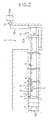
- Fig. 2 is a state for showing a state where lubricant is injected into a space between the outside of double-wall pipes and the ground;
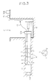
- Fig. 3 is a view for showing a state where lubricant is supplied from a side of the upper stream in the propelling direction to a double-wall pipe to be positioned in a section which is the farthest from a start vertical shaft, during the propulsion of double-wall pipes;
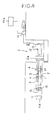
- Fig. 4 is a view for showing a state where lubricant is supplied from a side of the upper stream in the propelling direction to a double-wall pipe to be positioned in a second section next to the section which is the farthest from the start vertical shaft,during the propulsion of double-wall pipes;
- Fig. 5 is a view for showing a state where lubricant is supplied from a side of the upper stream to be positioned in the propelling direction to a double-wall pipe in a third section next to the second section;
- Fig. 6 is a view for showing a state where lubricant is supplied from a side of the down stream to a double-wall pipe to be positioned in a section which is the farthest from the start vertical shaft and the ground, during the propulsion of double-wall pipes;
- Fig. 7 is a view for showing a state where a conduit to be laid is divided into sections with a given length according to another method;
- Fig. 8 is a view for showing a state where lubricant is injected into a space between the outside of a double-wall pipe in a section which is the farthest from a start vertical shaft, during the propulsion of double-wall pipes;
- Fig. 9 is a view for showing a state where lubricant is injected into a space between the outside of a double-wall pipe to be positioned in a section which is positioned on a side of the start vertical shaft with respect to a section at about a center of the conduit, during the propulsion of double-wall pipes;
- Fig. 10 is a view for showing the construction of a double-wall pipe applied in the present invention;
- Fig. 11 is a view for showing a state where a space between the outside of double-wall pipes and the ground is filled with filler, after having laid a conduit; and
- Fig. 12 is a view for showing a state where a space formed between an inner pipe and an outer pipe of a double-wall pipe is filled with filler, after having laid a conduit.
- In a method of injecting lubricant into a space between the outside of double-wall pipes and the ground according to the present invention, lubricant is injected into a space between the outside of double-wall pipes and the ground, easily and surely, while propelling double-wall pipes each of which comprises an inner pipe and an outer pipe in the semi-shield process. Further, after having laid a conduit, a space between the outside of double-wall pipes and the ground is filled with filler as back-filling material, easily and in a short period and a space between an inner pipe and an outer pipe of each double-wall pipe is filled with filler as inside-filling material, easily and in a short period.
- First, a method of injecting lubricant into a space between the outside of double-wall pipes and the ground is explained.
- The propelling length, in which lubricant, which is injected into a space between the outside of double-wall pipes and the ground, shows the lubricant effect when laying conduit B, depends on the nature of the ground, however is nearly constant. Therefore, if new lubricant is injected into a space between the outside of double-wall pipes and the ground while the lubricant effect is maintained, double-wall pipes A can be always propelled at a state in which a frictional resistance between the outside of double-wall pipes and the ground is reduced.
- Namely, it is possible to maintain the lubricant effect of lubricant by injecting lubricant from the head double A connected with a tunneling machine and injecting new lubricant from a double-wall pipe A which is arranged behind the double-wall pipe at a distance from the head double-wall pipe in which the lubricant effect of lubricant injected into a space between the outside of double-wall pipes and the ground is shown or less into a space between the outside of double-wall pipes and the ground.
- Therefore, as shown in Fig. 1, a scheduled pipe of conduit B to be laid between a start vertical shaft C and an arrival vertical shaft D is divided into sections L1 to Ln each of which has a length in which lubricant shows the lubricant effect or less and which is equal to integral multiples of double-wall pipes. In the present embodiment, a length of section is set to 60 m, wherein ten double-wall pipes are included in one section.
- As shown in Fig. 2, double-wall pipe A comprises
inner pipe 1 andouter pipe 2.Supply pipe 3 for lubricant is provided betweeninner pipe 1 andouter pipe 2.Inner pipe 1 andouter pipe 2 are made of steel pipes with preset diameters, respectively.Inner pipe 1 of double-wall pipe A which has been propelled is welded toinner pipe 1 of new double-wall pipe A over the whole circumference, whilesupply pipe 3 of the double-wall pipe A which has been propelled is connected withsupply pipe 3 of the new double-wall pipe A throughjoint 5. -
Check valve 4 is provided at an end ofouter pipe 2. Checkvalve 4 is connected withsupply pipe 3. Checkvalve 4 allows lubricant to flow out ofouter pipe 2 into a space formed between the outside ofouter pipes 2 and the ground, but prevents earth and soil and subterranean water from entering into the inside of double-wall pipe A. Further,supply pipe 3 is secured to a place betweeninner pipe 1 andouter pipe 2. - Accordingly, lubricant can be sent to check
valve 4 throughsupply pipe 3 by closing an end of ansupply pipe 3 and connecting the other end thereof withpump 14 for forcing lubricant, and injected throughcheck valve 4 into a space between the outside of double-wall pipes A and the ground. Every time double-wall pipes are propelled by the length of each section,supply pipe 3 is connected withcheck valve 4 so that lubricant can be injected from the forefront double-wall pipe A in each section into a space between the outside of double-wall pipes and the ground. - In an embodiment shown in Fig. 2, an end of
supply pipe 3 is closed on a side of down stream in the propelling direction, and lubricant is supplied from a side of upper stream in the propelling direction to supplypipe 3. Lubricant may be supplied from a side of upper stream in the propelling direction in a case where the length of conduit B is short, as above-mentioned, lubricant can be injected into a space between the outside of double-wall pipes and the ground simultaneously from plural check valves which are connected with one supply pipe. However,when the length of conduit B is long and the number of sections L is numerous,many check valves 4 are connected withsupply pipe 3. Therefore, it is difficult to inject lubricant fromcheck valve 4 positioned at the most downstream side into a space between the outside of double-wall pipes and the ground. - Accordingly, it is preferable to provide
plural supply pipes 3 in parallel with each other betweeninner pipes 1 andouter pipes 2, and to connectindividual supply pipe 3 with acheck valve 4 corresponding to theindividual supply pipe 3. However, when manufacturing double-wall pipes, the number ofsupply pipes 3 which are provided between inner pipes and outer pipes should be not restricted. - Namely, when the number of sections in conduit B is preset, and the length of double-wall pipes A is preset, the number of double-wall pipes A are determined. Accordingly, in manufacturing process of double-wall pipes, double-wall pipes A corresponding to section L1 which is the most faraway section from a start vertical shaft are provided with one
supply pipe 3, respectively, double-wall pipes A corresponding to section L2 which is a section next to section L2 with two supply pipes, respectively, and in the same way, double-wall pipes A corresponding to section Ln are provided withn supply pipes 3, and when laying a conduit B, double-wall pipes can be propelled, while double-wall pipes corresponding to each section are selected. - Further, every double-wall pipe A may be provided with
n supply pipes 3 according to "n" of sections of conduit, wherein when propelling double-wall pipes A, the number ofused supply pipes 3 of double-wall pipes is selected for individual section L (1 to n). - Then, referring to Figs. 3 to 5, a method of supplying lubricant from a side of upper stream in the propelling direction of double-wall pipes A to double-wall pipe A, when laying conduit B by propelling double-wall pipes A from a start vertical shaft toward arrival vertical shaft D is explained.
- In propelling process, tunneling
machine 11 is arranged at the head. The ground is excavated bycutter head 11a of tunnelingmachine 11, while tunnelingmachine 11 is propelled by pipe-jackingmachine 12. - After tunneling
machine 11 has been propelled, a first double-wall pipe A being a component of conduit B is connected with tunnelingmachine 11. The double-wall pipe A corresponds to section L1 which is the most faraway section from the start vertical section C. Therefore,check valve 4 provided in the double-wall pipe A is connected withsupply pipe 3, and pump 14 is connected withsupply pipe 3 throughhose 13, so that lubricant intank 14a is supplied bypump 14 throughhose 13 andsupply pipe 3 to checkvalve 4, and injected throughcheck valve 4 into a space between the outside of double-wall pipes A and the ground, while propelling the first double-wall pipe, by which frictional resistance between double-wall pipes A and the ground is reduced so that double-wall pipes can be smoothly propelled. - After the first double-wall pipe A has been propelled,
push ring 12a of pipe-jackingmachine 12 is backtracked, thereafterhose 13 is disconnected fromsupply pipe 3 of the first double-wall pipe A. Then, a second double-wall pipe A is disposed on pipe-jackingmachine 12, and an end of the second double-wall pipe A is brought into contact with and welded to an end of the first double-wall pipe A, whilesupply pipe 3 of the first double-wall pipe is connected through joint 5 withsupply pipe 3 of the second double-wall pipe A. Then, aftersupply pipe 3 of the second double-wall pipe A has been connected withhose 13,push ring 12a is brought into the second double-wall pipe A and the second double-wall pipe A can be propelled bypush ring 12a, wherein lubricant is injected throughonly check valve 4 of the first double-wall pipe into a space between the outside of double-wall pipe and the ground(Fig. 3). - As above-mentioned, double-wall pipes A corresponding to section L1 are connected with each other in order, until the length of double-wall pipes connected with each other reaches to the length of section L1. After the propulsion of the double-wall pipe corresponding to the backward end of section L1 has been finished, double-wall pipe having the function as double-wall pipe A corresponding to the forward end of section L2 is disposed on pipe-jacking
machine 12. - Namely,
supply pipe 3 of the double-wall pipe A corresponding to the backward end of section L1 which has been propelled is connected withsupply pipe 3 of the double-wall pipe A corresponding to the head of section L2, while supply pipe 3 ( 3a ) is connected also to check valve 4( 4a ), wherein lubricant is injected from the double-wall pipe A corresponding to the head of section L1 and from the double-wall pipe A corresponding to the head of section L2, simultaneously into a space between the outside of double-wall pipes and the ground by which frictional resistance between the outside of double-wall pipes and the ground can be reduced so that double-wall pipes A can be smoothly propelled( Fig. 4). - As above-mentioned, the double-wall pipes A corresponding to sections L1 to Ln-1 are propelled. After the propulsion of double-wall pipe A corresponding to the backward end of section Ln-1 has been finished, double-wall pipe A having the function as the double-wall pipe A corresponding to the head of section Ln is disposed on pipe-jacking
machine 12, in the same manner. - Namely,
supply pipes 3 to 3n-1 of the double-wall pipe A corresponding to the backward end of section Ln-1 which has been propelled are connected withsupply pipes 3 to 3n-1 of the double-wall pipe A corresponding to the head of section Ln, while supply pipe 3( 3n ) of the double-wall pipe A is connected also to check valve 4( 4a ). Then,hoses 13 to 13n are connected withn supply pipes 3 to 3n-1, thereafter pump 14 is driven so that lubricant is supplied to supplypipes 3 to 3n-1, while propelling double-wall pipes 3 to 3n by pipe-jackingmachine 12,wherein lubricant is injected from the double-wall pipe A corresponding to the head of each section L1 to Ln,simultaneously into a space between the outside of double-wall pipes and the ground by which frictional resistance between the outside of double-wall pipes and the ground can be reduced so that double-wall pipes can be smoothly propelled( Fig.5 ). - As above-mentioned, in the present embodiment, when lubricant is injected into a space between the ground of double-wall pipes A and the ground,
hose 13 connected withpump 14 is connected withsupply pipe 3 provided in double-wall pipe A, then pump 14 is driven during the propulsion of double-wall pipes A, by which it is made possible to inject lubricant throughhose 13,supply pump 3, andcheck valve 4 into a space between the outside of double-wall pipes and the ground. Therefore, lubricant injecting operation is facilitated, and to smoothly propel double-wall pipes is made possible. - In the present invention, there is shown a case where different kind of double-wall pipes, such as the double-wall pipes A corresponding to section L1 each of which is provided with one
supply pipe 3, and the double-wall pipes A corresponding to section Ln each of which is provided with n supply pipes, are used. However, it is possible to lay conduit B using the double-wall pipes A each of which is previously provided with n supply pipes, wherein a supply pipe 3 (the number thereof: n-1 to 1) which is unused in the double-wall pipes A corresponding to each section L1 to Ln-1 are closed by a plug so that lubricant can be supplied to a desired section without being supplied to sections positioned on a side of upper stream with regard to the desired section. - Then, when conduit B is laid by propelling double-wall pipes A from start vertical shaft C toward an arrival vertical shaft D, a method is explained referring to Fig. 6, in which lubricant is supplied from a side of down stream in the propelling direction.
- In the present invention, in the same manner as in the above-mentioned embodiment of the present invention, conduit B to be laid is previously divided into plural sections L1 to Ln.
- As shown in the Fig.,
junction 16 havingplural valves 15 to 15n corresponding to the number of sections L are mounted in tunnelingmachine 11. Further,tube 17 which has one end to be connected withjunction 16 and has the other end to be connected throughhose 13 withpump 14 and the same length as a double-wall pipe is arranged withininner pipe 1. Thetube 17 is advanced together with the propulsion of double -wallpipe A. Tube 17 in the double-wall pipe is connected with anew tube 17 in new double-wall pipe A,when the double-wall pipe which has been propelled is connected with a new double-wall pipe. - The head double-wall pipe A of conduit B connected with tunneling
machine 11 corresponds to section L1 the most faraway from a start vertical shaft C, wherein supply pipes 3 (3 to 3n) are provided betweeninner pipes 1 andouter pipes 2 by the number according to the number (n) of sections. - When
valve 15 has the inner diameter more than 800 mm, a manually operated valve can be used. However, wheninner pipe 1 has the inner diameter under the above-mentioned diameter, an electromagnetic valve can be used asvalve 15. - When the double-wall to be positioned at the head in section L1 is propelled,
supply pipes 3 to 3n provided in the double-wall pipes are connected withvalves 15 to 15n provided in tunnelingmachine 11, respectively, whiletube 17 is connected withjunction 16,supply pipes 3 are connected withcheck valves 4, and an end ofsupply pipe 3 is closed by a plug. Then, thevalve 15 connected withsupply pipe 3 is opened, pump 14 is driven so that lubricant is sent throughjunction 16, thevalve 15, andsupply pipe 3 to checkvalve 4, and injected throughcheck valve 15 into a space between the outside of double-wall pipe and the ground, while double-wall pipe A is propelled. After the head double-wall pipe A has been propelled, the following double-wall pipe A is connected with the double-wall pipe A which has been propelled, wherein all thesupply pipes 3a to 3n except asupply pipe 3 of the double-wall pipe A which has been propelled are connected withsupply pipes 3a to 3n of the following double-wall pipe A, respectively. - After all the double-wall pipes A corresponding to section L1 have propelled, double-wall pipe A to be positioned at the head in section L2 is connected with the double-wall pipe A to be positioned at the backward end in section L1, wherein
supply pipes 3a to 3n of the double-wall pipe A which has been propelled are connected withsupply pipe 3a to 3n of a new double-wall pipe,supply pipe 3a is connected withcheck valve 4a, and an end ofsupply pipe 3a is closed by a plug. Then,valve 15a connected withsupply pipe 3a is opened, while tunnelingmachine 11 and double-wall pipes A which follows tunnelingmachine 11 are propelled. While propelling double-wall pipes, lubricant is injected from the double-wall pipe A to be positioned at the head in section L1 and from the double-wall pipe A to be positioned at the head in section L2 into a space between the outside of double-wall pipes and the ground. - After all the double-wall pipes A corresponding to section L2 has been propelled, in the same manner as above-mentioned embodiment, double-wall pipes A corresponding to the succeeding section L3 to Ln are connected in order, to the double-wall pipe A at the rear in section L2, while
supply pipes 3 of the double-wall pipe A which has been propelled are connected withsupply pipes 3 of a double-wall pipe which follows the double-wall pipe A which has been propelled, and lubricant is simultaneously injected from the double-wall pipe A to be positioned at the head in each section L. - As above-mentioned, frictional resistance between the outside of double-wall pipes A and the ground can be reduced by simultaneously injecting from double-wall pipes A to be positioned at the head in each section L into a space between the outside of double-wall pipes and the ground so that tunneling
machine 11 and double-wall pipes A which follows tunnelingmachine 11 can be smoothly propelled. - Then, referring to Figs. 7 to 10, a method of injecting lubricant into a space between the outside of double-wall pipes and the ground is explained. In this method, double-wall pipes A are propelled from start vertical shaft C to an arrival vertical shaft so that conduit B is laid, wherein in sections, which lie on the arrival vertical shaft side, lubricant is supplied from the downstream side in the propelling direction to double-wall pipe A, while in sections which lie on the start vertical shaft side, lubricant is supplied from the upstream side in the propelling direction to double-wall pipe A.
- In the present embodiment, conduit B to be laid is divided into plural sections in the same manner as the above-mentioned embodiments. Among divided sections, a section which is positioned at the center of conduit B is designated as section o, sections which are positioned between section o and arrival vertical shaft D are designated as sections p1 to pn, and sections which are positioned between section o and start vertical shaft C are designated as sections q1 to qn.
- In sections p1 to pn, in the same manner as the second embodiment, lubricant is supplied from the head double-wall pipe A which follows tunneling
machine 11 to checkvalve 4, and injected throughcheck valve 4 into a space between the outside of double-wall pipes and the ground, while in sections q1 to qn, in the same manner as the first embodiment,lubricant is supplied from the double-wall pipe A which is disposed on the start vertical shaft C side to checkvalve 4, and injected throughcheck valve 4 into a space between the outside of double-wall pipes A and the ground. - Namely, after tunneling
machine 11 provided withjunction 16 has been propelled, tunnelingmachine 11 and the head double-wall pipe A which is a component of conduit B following tunnelingmachine 11 are propelled. The double-wall pipe A corresponds to the farthest section pn from start vertical shaft C. Therefore, double-wall pipes A provided withsupply pipes 3 the number of which corresponds to the number n of sections between the central section o and arrival vertical shaft D are selectively used as double-wall pipes A, wherein thesesupply pipes 3 are connected withvalves 15 provided injunction 16, respectively.Tube 17 for sending lubricant is inserted withininner pipe 1. One end oftube 17 is connected withjunction 16, while the other end oftube 17 is connected throughhose 13 withpump 14. - After preparations have been made for propelling of the head double-wall A as above-mentioned, tunneling
machine 11 and the head double-wall pipe A are propelled by pipe-jackingmachine 12, while lubricant is pumped throughhose 13,tube 17,supply pipe 3 to checkvalve 4 bypump 14, and injected throughcheck valve 4 into a space between the outside of double-wall pipe A and the ground. Then, after the head double-wall pipe A has been propelled,push ring 12a of pipe-jackingmachine 12 is moved back, then a second double-wall pipe A is put on pipe-jackingmachine 12, and a front end ofinner pipe 1 of the second double-wall pipe A is welded to the rear end ofinner pipe 1 in the head double-wall pipe A. - Then,
supply pipes 3 of the head double-wall pipe A are connected through a joint withsupply pipes 3 of the second double-wall pipe A, a rear end ofsupply pipe 3 of the second double-wall pipe A is closed by plug, and anew tube 17 in the head double-wall pipe A is connected with atube 17 in the second double-wall pipe A, and thereafter pushring 12a is brought into contact with the second double-wall pipe A, and tunnelingmachine 11 and double-wall pipes A are propelled by pipe-jackingmachine 12, while lubricant is injected from only the head double-wall pipe A into a space between the outside of double-wall pipes and the ground(Fig. 8). - Then, in the same manner as a case of the second embodiment, double-wall pipes A corresponding to sections pn-1 to p1 are connected in order, to the second double-wall pipe A, and tunneling
machine 11 and double-wall pipes A are propelled, while lubricant is injected from double-wall pipes A to be positioned at the head in each section pn to p1 into a space between the outside of double-wall pipes A and the ground. - After all double-wall pipes A corresponding to sections pn to p1 have been propelled as above-mentioned, a new double-wall pipe A, which is to be positioned at the head in section o, is put on pipe-jacking
machine 12, wherein double-wall pipe A provided with onesupply pipe 3 is selected as the new double-wall pipe. One end of thesupply pipe 3 is connected withcheck valve 4 in the new double-wall pipe A and the other end of thesupply pipe 3 is connected withhose 18 arranged in start vertical shaft C double-wall pipes A and the ground. Thehose 18 is connected throughvalves 19a withpump 14 provided indistributor 19. - After the preparation for propelling double-wall pipes A corresponding to the central section o the double-wall pipes A have been propelled in the same manner as above-mentioned,wherein lubricant is injected simultaneously from double-wall pipes A to be positioned at the head in sections pn to p1, and o, into a space between the outside of double-wall pipes and the ground. When the propulsion of double-wall pipe A corresponding to section o has been finished, a new double-wall pipe A corresponding to section q1 is put on pipe-jacking
machine 12, wherein double-wall pipe A provided with twosupply pipes 3 are selected as the new double-wall pipe, and propelled. Thereafter, in the same manner as the first embodiment, double-wall pipes A corresponding to sections q1 to qn are selected and propelled, while lubricant is simultaneously injected from double-wall pipes A which is to be positioned at the head in each section q1 to qn so that the propulsion of double-wall pipes are easily made. - As above-mentioned, in the present embodiment, even in case of
supply pipes 3 connected with each other having the longest total length, a total length of connected supply pipes is a half of the length of conduit B, and the number of supply pipes needed for supplying lubricant to check valves is a half as compared as a case where lubricant is supplied from only one vertical shaft side. Therefore, line resistance which is generated when lubricant is sent throughsupply pipes 3 can be reduced sharply, and the diameter ofsupply pipes 3 can be made small. As supply pipes can be made thin and the number of supply pipes can be reduced, the diameter ofouter pipes 2 can be made small, while the diameter ofinner pipe 1 is maintained at a given value. Accordingly, the tunneling machine can be made compact and the amount of excavated earth and soil can be reduced. - Then, a method of injecting back-filling material as filler into a space formed between the outside of conduit B laid between start vertical shaft C and arrival vertical shaft D and the ground is explained, referring to Fig. 10.
- After conduit B has been laid, tunneling
machine 11 is disconnected from the head double-wall pipe A and taken out from arrival vertical shaft D. Thereafter,distributor 20 is connected withtube 17, and withsupply pipes 3 corresponding to sections p1 to pn which are positioned on the arrival vertical shaft side ofconduit B. Tank 14b in which back-filling material is put is connected withpump 14.Supply pipes 3 of double-wall pipes corresponding to sections q1 to qn which are positioned on the start vertical shaft side are connected withdistributor 19 provided in start vertical shaft C in order to maintain the state where lubricant is supplied to checkvalves 4. - When
pump 14 is driven under the above-mentioned condition, back-filling material intank 14b is sent throughtube 17,distributor 20, andsupply pipe 3 to checkvalves 4 in sections p which are positioned on the arrival vertical shaft side to checkvalves 4 in sections p which are positioned on the arrival vertical shaft side , and injected through thecheck valve 4 into a space between the outside of double-wall pipes and the ground and at the same time buck-filling materials is sent throughhose 18 andsupply pipes 3 to checkvalves 4 in the central section o and each of sections g which are positioned on the start vertical shaft side, and injected throughcheck valves 4 in the central section o and each of sections q which are positioned on the start vertical shaft side into a space between the outside of double-wall pipes and the ground. - As above-mentioned, back-filling material can be injected from
check valves 4 in the respective sections of conduit B which has been laid simultaneously by which the time needed for filling a space between the outside of double-wall pipes and the ground with back-filling material can be reduced. In order to inject back-filling material into a space between the outside of double-wall pipes and the ground, pumps may be provided in respective vertical shafts C,D, respectively so that back-filling material can be supplied simultaneously to checkvalves 4 in sections p which are positioned on the arrival vertical shaft side, section o and sections q which are positioned on the start vertical shaft side from different pumps. - Then, a method of injecting inside-filling material as filler into a space formed between
inner pipe 1 andouter pipe 2 of double-wall pipe A is explained, referring to Figs. 11 and 12. - First, the construction of double-wall pipe A used when a method according to the present invention is carried out is explained, referring to Fig. 11.
Inner pipe 1 andouter pipe 2 are arranged so as to be relatively movable in the longidinal direction throughbrackets 21 so that aspace 22 is formed betweeninner pipe 1 andouter pipe 2. Betweeninner pipe 1 andouter pipe 2,sheath pipes 23 are provided, in which supplypipes 3 are inserted, wherein a second double-wall pipe is formed of thesheath pipes 23 and thesupply pipes 3. End portions ofsheath pipes 23 are opened and projected intospace 22 formed betweeninner pipe 1 andouter pipe 2. - As double-wall pipes A, double-wall pipes provided with one
sheath pipe 23 and onesupply pipe 3, and double-wall pipes provided with 2 to n of sheath pipes and 2 to n of supply pipes are provided, wherein the second double-wall pipe composed ofsheath pipe 23 andsupply pipe 3 is different from double-wall pipe composed of inner pipe and outer pipe in the function, and the structure composed ofsheath pipe 23 andsupply pipe 3 is merely called as the second double-wall pipe from the structural analogy. Therefore, in the following explanation,sheath pipe 23, andsupply pipes 3 are handled as being independent. - After conduit B has been laid between start vertical shaft C and arrival vertical shaft D,
space 22 opening toward arrival vertical shaft D of conduit B and toward start vertical shaft C is sealed off by sealingmember 24.Sheath pipes 23 of double-wall pipes A corresponding to the respective sections p opening toward arrival shaft D are connected throughhoses 18 with distributingmember 20, whilesheath pipes 23 of double-wall pipes A corresponding to the respective sections q opening toward start vertical shaft C are connected throughhoses 18 withdistributer 19 connected with a pump. - After
sheath pipes 23 corresponding to the respective sections have been connected with a pump as above-mentioned, the pump is driven so that inside-filling material is supplied throughtube 17,distributor 20, andsheath pipes 23 to double-wall pipes A corresponding to checkvalves 4 in the respective sections p which are positioned on the arrival vertical shaft side and injected through openings ofsheath pipes 23 intospace 22, while inside-filling material is supplied throughhoses 18, andsheath pipes 23 to double-wall pipes A corresponding to checkvalves 4 in the respective sections q which are positioned on the start vertical shaft side and injected through openings ofsheath pipes 23 intospace 22. - Accordingly, inside-filling material can be injected simultaneously from the start vertical shaft C side and from the arrival vertical shaft D side in
space 22 formed betweeninner pipe 1 andouter pipe 2, so that the operation of injecting inside-filling material can be carried out easily and in less time.
Claims (15)
- A method of injecting lubricant into a space between the outside of double-wall pipes and the ground in the propelling process of double-wall pipes comprising the steps of:preparing double-wall pipes (A), each of which comprises an inner pipe (1) and an outer pipe (2), and has at least one supply pipe (3) for lubricant provided between the inner pipe and the outer pipe and a discharge port formed in the outer pipe;propelling a tunnelling machine (11) and a first pipe of said double-wall pipes (A) following the tunnelling machine from a start vertical shaft (C) toward an arrival vertical shaft (D) by a pipe-jacking machine (12);connecting a supply pipe of the first double-wall pipe which has been propelled with a supply pipe of a second pipe of said double-wall pipes (A);connecting the supply pipe of the second double-wall pipe with a lubricant feeder (14);thereafter propelling the tunnelling machine and the first and second double-wall pipes following the tunnelling machine by the pipe-jacking machine, while lubricant is pumped through the supply pipes to the discharge ports by the lubricant feeder and injected through the discharge ports into a space between the outside of the double-wall pipes and the ground.
- A method as claimed in Claim 1 wherein the supply pipe of the second double-wall pipe is connected at its downstream end with the supply pipe of the first double-wall pipe and at its upstream end with the lubricant feeder, and the lubricant is supplied from an upstream side in a propelling direction to the discharge ports in the double-wall pipes.
- A method as claimed in Claim 2 whereinvarious kinds of double-wall pipes (A) are prepared, each kind of pipe being provided with a different number of supply pipes (3) between the inner pipe (1) and the outer pipe (2),the line along which a conduit is to be laid is divided into sections (L) each having a given length in which pipes of one kind are to be laid,double-wall pipes (A) of the kind having the smallest number of supply pipes (3) are chosen for the farthest section from the start vertical shaft (C),double-wall pipes (A) of the kind having a number of supply pipes (3) which is at least one more than the smallest number of supply pipes are chosen for the section adjacent to the farthest section on the start vertical shaft side,and so forth, double-wall pipes of the kind having a number of supply pipes which is at least one more than the number of supply pipes in the double-wall pipes in the section adjacent thereto on the arrival vertical shaft side being chosen for each respective section in the direction from the arrival vertical shaft (D) to the start vertical shaft (C),wherein the chosen double-wall pipes are arranged in order of increasing number of supply pipes from the arrival vertical shaft toward the start vertical shaft and are propelled following the tunnelling machine (11).
- A method as claimed in Claim 3 wherein a junction member (16) is provided in the lubricant feeder in order that lubricant discharge from the lubricant feeder is sent to a plurality of lines, and the supply pipes (3) in the double-wall pipes are connected with lubricant feeding holes in the junction member.
- A method as claimed in Claim 2 whereindouble-wall pipes (A) provided with a plurality of supply pipes (3) between the inner pipes (1) and the outer pipes (2) are prepared,the line along which a conduit is to be laid is divided into sections (L) each having a given length,one supply pipe (3) chosen from the plurality of supply pipes in each double-wall pipe is used for distributing lubricant to the double-wall pipes while the double-wall pipes corresponding to the farthest section from the start vertical shaft are being propelled,the chosen supply pipe and at least one supply pipe chosen from the rest of the plurality of supply pipes is used for distributing lubricant to the double-wall pipes while the double-wall pipes corresponding to the section adjacent to the farthest section on the start vertical shaft side are being propelled,and so forth, the number of supply pipes used in each respective section being at least one more than the number of supply pipes used in the section adjacent thereto on the arrival vertical shaft side.
- A method as claimed in Claim 5 wherein a junction member (16) is provided in the lubricant feeder in order that lubricant discharged from the lubricant feeder is sent to a plurality of lines, and the supply pipes (3) in the double-wall pipes are connected with lubricant feeding holes in the junction member.
- A method as claimed in Claim 1 wherein the head double-wall pipe (A) immediately following the tunnelling machine (11) is connected with the lubricant feeder (14), by which lubricant is supplied to the supply pipes of the head double-wall pipe from the downstream side in the propelling direction.
- A method as claimed in Claim 7 whereinvarious kinds of double-wall pipes (A) are prepared, each kind of pipe being provided with a different number of supply pipes (3) between the inner pipe (1) and the outer pipe (2),the line along which a conduit is to be laid is divided into sections (L) each having a given length in which pipes of one kind are to be laid,double-wall pipes of the kind having the largest number of supply pipes are chosen for the farthest section from the start vertical shaft (C),double-wall pipes of the kind having a number of supply pipes which is at least one less than the largest number of supply pipes are chosen for the section adjacent to the farthest section on the start vertical shaft side,and so forth, double-wall pipes of the kind having a number of supply pipes which is at least one less than the number of supply pipes in the double-wall pipes in the section adjacent thereto on the arrival vertical shaft side being chosen for each respective section in the direction from the arrival vertical shaft side to the start vertical shaft side,wherein the chosen double-wall pipes (A) are arranged in order of decreasing number of supply pipes from the arrival vertical shaft (D) toward the start vertical shaft (C) and are propelled following the tunnelling machine (11).
- A method as claimed in Claim 8 wherein a junction member (16) is provided in the lubricant feeder (14) in order that lubricant discharged from the lubricant feeder is sent to a plurality of lines, and the supply pipes (3) in the double-wall pipes are connected with lubricant feeding holes in the junction member.
- A method as claimed in Claim 7 whereindouble-wall pipes (A) provided with a plurality of supply pipes (3) between the inner pipes (1) and the outer pipes (2) are prepared,the line along which a conduit is to be laid is divided into n sections (L1 to Ln) each having a given length,n supply pipes chosen from the plurality of supply pipes in each double-wall pipe are used for distributing lubricant while the double-wall pipes corresponding to the farthest section from the start vertical shaft are propelled,all except at least one of the chosen supply pipes in the second section adjacent to the farthest section from the start vertical shaft are used for distributing lubricant while the double-wall pipes corresponding to the second section are propelled,and so forth, the number of supply pipes used in each respective section while double-wall pipes corresponding to the respective section are propelled, is at least one less than the number of supply pipes used in the section adjacent thereto on the arrival vertical shaft side.
- A method as claimed in Claim 10 wherein a junction member (16) is provided in the lubricant feeder in order that lubricant discharged from the lubricant feeder is sent to a plurality of lines, and the supply pipes (3) in the double-wall pipes are connected with lubricant feeding holes in the junction member.
- A method as claimed in Claim 1 wherein the line along which a conduit is to be laid is divided into two zones, the first zone being on the arrival vertical shaft (D) side of the centre of the conduit and the second zone being on the start vertical shaft (C) side of the centre of the conduit,wherein during propulsion of the double-wall pipes (A) which are to be positioned in the first zone, lubricant is injected into a space between the outside of the double-wall pipes and the ground through supply pipes (3) in the head double-wall pipe which immediately follows the tunnelling machine (11),and wherein during propulsion of the double-wall pipes (A) which are to be positioned in the second zone, lubricant is injected into a space between the outside of the double-wall pipes and the ground through supply pipes (3) in the rearmost double-wall pipe following the tunnelling machine (11).
- A method as claimed in Claim 12 whereinvarious kinds of double-wall pipes (A) are prepared, each kind of pipe being provided with a different number of supply pipes (3) between the inner pipe (1) and the outer pipe (2),the line along which a conduit is to be laid is divided into sections (0, p, q) each having a given length in which pipes of one kind are to be laid,double-wall pipes of the kind having the smallest number of supply pipes are chosen for the central section (o) of the scheduled line,double-wall pipes of the kind having a number of supply pipes which is at least one more than the above-mentioned smallest number are chosen for the sections (p1, q1) adjacent to the central section on both the start vertical shaft side and the arrival vertical shaft side of the central section,and so forth, double-wall pipes of the kind having a number of supply pipes which is at least one more than the number of supply pipes used in the section adjacent thereto on the arrival vertical shaft side being chosen in the direction away from the central section (o),wherein a tunnelling machine (11) and the chosen double-wall pipes (A) arranged in order of decreasing number of supply pipes following the tunnelling machine are propelled, following which the double-wall pipe provided with the smallest number of supply pipes for the central section is propelled, and thereafter the double-wall pipes for sections between the central section and the start vertical shaft are propelled in order of increasing number of supply pipes.
- A method of injecting filler in the propelling process of double-wall pipes whereina conduit comprised of double-wall pipes (A) is laid, each double-wall pipe comprising an inner pipe (1) and an outer pipe (2), the conduit being provided with a plurality of supply pipes (3) between the inner pipe (1) and the outer pipe (2) and discharge ports in the outer pipes with which the supply pipes are connected;and thereafter filler is supplied from the start vertical shaft and from the arrival vertical shaft to the supply pipes and injected into a space between the outside of the double-wall pipes and the ground.
- A method of injecting filler in the propelling process of double-wall pipes,wherein a first double-wall pipe comprises an inner pipe (1) and an outer pipe (2),a sheath pipe (23) is arranged within the space formed between said inner pipe (1) and said outer pipe (2), and communicates at its open end with the space,lubricant is supplied to the inside of the sheath pipe,a supply pipe (3), with which a discharge port for discharging lubricant to the outside of the first double-wall pipe is connected, is inserted in the sheath pipe so that a second double-wall pipe is formed,the first double-wall pipe (A) being laid to form part of a conduit between a start vertical shaft (C) and an arrival vertical shaft (D), thereafter filler being supplied from the start vertical shaft side and from the arrival vertical shaft side to the sheath pipe so that the space between the inner pipe (1) and the outer pipe (2) is filled with filler.
Applications Claiming Priority (6)
| Application Number | Priority Date | Filing Date | Title |
|---|---|---|---|
| JP5065945A JP2937682B2 (en) | 1993-03-03 | 1993-03-03 | Sliding material injection method in double pipe propulsion method |
| JP65945/93 | 1993-03-03 | ||
| JP85114/93 | 1993-03-22 | ||
| JP8511493A JP2937685B2 (en) | 1993-03-22 | 1993-03-22 | Sliding material injection method in double pipe propulsion method |
| JP279296/93 | 1993-11-09 | ||
| JP27929693A JP3257881B2 (en) | 1993-11-09 | 1993-11-09 | Sliding material injection method in double pipe propulsion method |
Publications (2)
| Publication Number | Publication Date |
|---|---|
| EP0613992A1 EP0613992A1 (en) | 1994-09-07 |
| EP0613992B1 true EP0613992B1 (en) | 1997-10-15 |
Family
ID=27298977
Family Applications (1)
| Application Number | Title | Priority Date | Filing Date |
|---|---|---|---|
| EP94301339A Expired - Lifetime EP0613992B1 (en) | 1993-03-03 | 1994-02-24 | Method for driving pipes into the ground |
Country Status (4)
| Country | Link |
|---|---|
| US (1) | US5484232A (en) |
| EP (1) | EP0613992B1 (en) |
| KR (1) | KR100229397B1 (en) |
| DE (1) | DE69406156T2 (en) |
Families Citing this family (26)
| Publication number | Priority date | Publication date | Assignee | Title |
|---|---|---|---|---|
| EP0639690A4 (en) * | 1993-03-05 | 1997-04-09 | Kawasaki Steel Co | DUAL-WALL CONDUIT FOR EXCAVATION TECHNIQUES, AND CONFIGURATION OF THE END OF THE MOTHER CONDUCT. |
| US5482404A (en) * | 1993-07-27 | 1996-01-09 | Tenbusch, Ii; Albert A. | Underground pipe replacement technique |
| DE19513181A1 (en) * | 1995-03-31 | 1996-10-02 | Siegfried Schwert | Method and device for pulling a pipe laid or to be laid in the ground |
| SG60092A1 (en) * | 1996-09-05 | 1999-02-22 | Toyo Technos Co Ltd | Semi-shield method and apparatus for the same |
| US20070044957A1 (en) * | 2005-05-27 | 2007-03-01 | Oil Sands Underground Mining, Inc. | Method for underground recovery of hydrocarbons |
| US8287050B2 (en) | 2005-07-18 | 2012-10-16 | Osum Oil Sands Corp. | Method of increasing reservoir permeability |
| CA2649850A1 (en) * | 2006-04-21 | 2007-11-01 | Osum Oil Sands Corp. | Method of drilling from a shaft for underground recovery of hydrocarbons |
| EP2035645B1 (en) * | 2006-06-16 | 2014-10-15 | Vermeer Manufacturing Company | Microtunnelling system and apparatus |
| US20080078552A1 (en) * | 2006-09-29 | 2008-04-03 | Osum Oil Sands Corp. | Method of heating hydrocarbons |
| US7644769B2 (en) * | 2006-10-16 | 2010-01-12 | Osum Oil Sands Corp. | Method of collecting hydrocarbons using a barrier tunnel |
| WO2008064305A2 (en) * | 2006-11-22 | 2008-05-29 | Osum Oil Sands Corp. | Recovery of bitumen by hydraulic excavation |
| GB2453447A (en) * | 2007-04-27 | 2009-04-08 | Cambridge Semiconductor Ltd | A protection scheme for a switched-mode power converter |
| CA2780141A1 (en) * | 2007-09-28 | 2009-04-02 | Osum Oil Sands Corp. | Method of upgrading bitumen and heavy oil |
| US7783145B2 (en) * | 2007-10-15 | 2010-08-24 | Hewlett-Packard Development Company, L.P. | Electrode having nanofilaments |
| CA2698238C (en) * | 2007-10-22 | 2014-04-01 | Osum Oil Sands Corp. | Method of removing carbon dioxide emissions from in-situ recovery of bitumen and heavy oil |
| CA2701164A1 (en) * | 2007-12-03 | 2009-06-11 | Osum Oil Sands Corp. | Method of recovering bitumen from a tunnel or shaft with heating elements and recovery wells |
| US8176982B2 (en) * | 2008-02-06 | 2012-05-15 | Osum Oil Sands Corp. | Method of controlling a recovery and upgrading operation in a reservoir |
| US8209192B2 (en) | 2008-05-20 | 2012-06-26 | Osum Oil Sands Corp. | Method of managing carbon reduction for hydrocarbon producers |
| US8256536B2 (en) * | 2009-02-11 | 2012-09-04 | Vermeer Manufacturing Company | Backreamer for a tunneling apparatus |
| DE102012002417A1 (en) * | 2012-02-08 | 2013-08-08 | Herrenknecht Ag | Lubricant supply to a bore for laying a pipeline |
| KR101944262B1 (en) * | 2018-09-12 | 2019-01-30 | 주식회사 강물 | Simultaneous propulsion construction method using double pipe |
| CN110762286B (en) * | 2019-10-31 | 2021-09-24 | 中铁十八局集团有限公司 | Drainage pipe network artificial pipe jacking construction process |
| CN110925489A (en) * | 2019-12-12 | 2020-03-27 | 贵州建工集团第一建筑工程有限责任公司 | Opposite jacking and butt joint construction method for finished pipes |
| CN111749292B (en) * | 2020-07-02 | 2022-04-01 | 北京城建集团有限责任公司 | Construction process for grooving wall-connecting ground in pipeline dense area |
| CN112377203B (en) * | 2020-11-10 | 2022-09-23 | 常熟市市政建设有限责任公司 | Construction method for repairing large-deviation jacking pipe by reversely jacking steel sleeve |
| CN113550758A (en) * | 2021-08-03 | 2021-10-26 | 广州市市政集团有限公司 | Guide type miniature pipe jacking construction method |
Family Cites Families (13)
| Publication number | Priority date | Publication date | Assignee | Title |
|---|---|---|---|---|
| US4176985A (en) * | 1975-07-14 | 1979-12-04 | Reading And Bates Construction Co. | System and method for installing production casings |
| US4422800A (en) * | 1980-11-21 | 1983-12-27 | Doc's Road Boring, Inc. | Method of installing an underground conduit |
| US4576515A (en) * | 1982-09-20 | 1986-03-18 | Nippon Telegraph & Telephone Public Corp. | Pipe laying apparatus |
| US4785885A (en) * | 1987-05-13 | 1988-11-22 | Cherrington Martin D | Method and apparatus for cementing a production conduit within an underground arcuate bore |
| DE3826513A1 (en) * | 1988-08-04 | 1990-02-08 | Schmidt Paul | METHOD AND RAMM DRILLING DEVICE FOR THE TRENCHLESS LAYING OF SUPPLY LINES |
| FR2635799B1 (en) * | 1988-08-26 | 1992-04-03 | Montcocol | METHOD AND DEVICE FOR LAYING DOWN UNDERGROUND PIPES |
| JP2642717B2 (en) * | 1988-12-12 | 1997-08-20 | 株式会社クボタ | Propulsion method propulsion device |
| US4925344A (en) * | 1989-01-03 | 1990-05-15 | Peres Steve U | Method and apparatus for replacing buried pipe |
| BE1003560A3 (en) * | 1989-10-06 | 1992-04-21 | Smet Marc Jozef Maria | High pressure pipe and device for making a hole in the ground with such high pressure pipe. |
| JPH086558B2 (en) * | 1989-10-11 | 1996-01-24 | 日本鋼管株式会社 | Underground drilling equipment |
| US5241993A (en) * | 1989-12-06 | 1993-09-07 | Stephens Patrick J | Method for grouting cavities using a pumpable cement grout |
| US5063967A (en) * | 1989-12-06 | 1991-11-12 | Stephens Patrick J | Pumpable cement grout |
| CA2123298C (en) * | 1991-11-13 | 2001-01-23 | Reginald G. Handford | Trenchless pipeline replacement |
-
1994
- 1994-02-15 US US08/196,443 patent/US5484232A/en not_active Expired - Fee Related
- 1994-02-22 KR KR1019940003085A patent/KR100229397B1/en not_active Expired - Fee Related
- 1994-02-24 EP EP94301339A patent/EP0613992B1/en not_active Expired - Lifetime
- 1994-02-24 DE DE69406156T patent/DE69406156T2/en not_active Expired - Fee Related
Also Published As
| Publication number | Publication date |
|---|---|
| DE69406156T2 (en) | 1998-04-02 |
| EP0613992A1 (en) | 1994-09-07 |
| KR940021973A (en) | 1994-10-19 |
| US5484232A (en) | 1996-01-16 |
| DE69406156D1 (en) | 1997-11-20 |
| KR100229397B1 (en) | 1999-11-01 |
Similar Documents
| Publication | Publication Date | Title |
|---|---|---|
| US5484232A (en) | Method for injecting lubricant and filler in the pipe-jacking method | |
| US4793736A (en) | Method and apparatus for continuously boring and lining tunnels and other like structures | |
| EP0750096B1 (en) | A method for injecting back-filling material into a space between the outside of double-wall pipes and the ground in the pipe-jacking method | |
| US4915541A (en) | Method and apparatus for continuously boring and lining tunnels and other like structures | |
| KR101439098B1 (en) | System and method for mixing cement sluury for cementing, and system and method for cementing space between casing and drug well of high depth | |
| JP3257881B2 (en) | Sliding material injection method in double pipe propulsion method | |
| AU635626B2 (en) | A propulsion process for burying a pipe | |
| JP2937685B2 (en) | Sliding material injection method in double pipe propulsion method | |
| JP2000192780A (en) | Friction reducing construction method for propelling pipe, and propelling pipe friction reducing device | |
| JP3181242B2 (en) | Equipment for middle pressing method | |
| JP4692706B2 (en) | Hume pipe for propulsion method | |
| CN113431596A (en) | Rotatable hard rock advanced cutting system | |
| JP4138796B2 (en) | Steel pipe placing method and steel pipe placing tool | |
| JPS62280491A (en) | Method of pre-fabricated perforated pipe propulsion construction | |
| JP2937682B2 (en) | Sliding material injection method in double pipe propulsion method | |
| JP3689755B2 (en) | Hume tube for propulsion | |
| JP6804067B2 (en) | Tunnel boring machine | |
| JPH07224591A (en) | Injection method of lubricant in double pipe propulsion method | |
| JPH01137094A (en) | Method of excavation construction of tunnel, etc. and injector used for said method of construction | |
| JP2991819B2 (en) | Underground propulsion device and underground propulsion method | |
| JP2001241291A (en) | Sliding material injection method for propulsion method | |
| JPH07180484A (en) | Steel pipe jacking method and device | |
| JP6230284B2 (en) | Existing pipe renewal method | |
| JPH06257384A (en) | Method of injecting backing material in double pipe propulsion method | |
| JP2002213189A (en) | Filler injecting method for use in pipe jacking method, and propelling apparatus |
Legal Events
| Date | Code | Title | Description |
|---|---|---|---|
| PUAI | Public reference made under article 153(3) epc to a published international application that has entered the european phase |
Free format text: ORIGINAL CODE: 0009012 |
|
| AK | Designated contracting states |
Kind code of ref document: A1 Designated state(s): DE FR GB |
|
| 17P | Request for examination filed |
Effective date: 19940829 |
|
| 17Q | First examination report despatched |
Effective date: 19960110 |
|
| GRAG | Despatch of communication of intention to grant |
Free format text: ORIGINAL CODE: EPIDOS AGRA |
|
| GRAH | Despatch of communication of intention to grant a patent |
Free format text: ORIGINAL CODE: EPIDOS IGRA |
|
| GRAH | Despatch of communication of intention to grant a patent |
Free format text: ORIGINAL CODE: EPIDOS IGRA |
|
| GRAA | (expected) grant |
Free format text: ORIGINAL CODE: 0009210 |
|
| AK | Designated contracting states |
Kind code of ref document: B1 Designated state(s): DE FR GB |
|
| REF | Corresponds to: |
Ref document number: 69406156 Country of ref document: DE Date of ref document: 19971120 |
|
| ET | Fr: translation filed | ||
| PLBE | No opposition filed within time limit |
Free format text: ORIGINAL CODE: 0009261 |
|
| STAA | Information on the status of an ep patent application or granted ep patent |
Free format text: STATUS: NO OPPOSITION FILED WITHIN TIME LIMIT |
|
| 26N | No opposition filed | ||
| REG | Reference to a national code |
Ref country code: GB Ref legal event code: IF02 |
|
| PGFP | Annual fee paid to national office [announced via postgrant information from national office to epo] |
Ref country code: FR Payment date: 20020212 Year of fee payment: 9 |
|
| PGFP | Annual fee paid to national office [announced via postgrant information from national office to epo] |
Ref country code: GB Payment date: 20020227 Year of fee payment: 9 |
|
| PGFP | Annual fee paid to national office [announced via postgrant information from national office to epo] |
Ref country code: DE Payment date: 20020314 Year of fee payment: 9 |
|
| PG25 | Lapsed in a contracting state [announced via postgrant information from national office to epo] |
Ref country code: GB Free format text: LAPSE BECAUSE OF NON-PAYMENT OF DUE FEES Effective date: 20030224 |
|
| PG25 | Lapsed in a contracting state [announced via postgrant information from national office to epo] |
Ref country code: DE Free format text: LAPSE BECAUSE OF NON-PAYMENT OF DUE FEES Effective date: 20030902 |
|
| GBPC | Gb: european patent ceased through non-payment of renewal fee | ||
| PG25 | Lapsed in a contracting state [announced via postgrant information from national office to epo] |
Ref country code: FR Free format text: LAPSE BECAUSE OF NON-PAYMENT OF DUE FEES Effective date: 20031031 |
|
| REG | Reference to a national code |
Ref country code: FR Ref legal event code: ST |