EP0612933A1 - Vibration control device for rotating machine - Google Patents
Vibration control device for rotating machine Download PDFInfo
- Publication number
- EP0612933A1 EP0612933A1 EP94400399A EP94400399A EP0612933A1 EP 0612933 A1 EP0612933 A1 EP 0612933A1 EP 94400399 A EP94400399 A EP 94400399A EP 94400399 A EP94400399 A EP 94400399A EP 0612933 A1 EP0612933 A1 EP 0612933A1
- Authority
- EP
- European Patent Office
- Prior art keywords
- yoke
- shaft
- vibration
- control device
- electromagnet
- Prior art date
- Legal status (The legal status is an assumption and is not a legal conclusion. Google has not performed a legal analysis and makes no representation as to the accuracy of the status listed.)
- Granted
Links
Images


Classifications
-
- H—ELECTRICITY
- H02—GENERATION; CONVERSION OR DISTRIBUTION OF ELECTRIC POWER
- H02K—DYNAMO-ELECTRIC MACHINES
- H02K7/00—Arrangements for handling mechanical energy structurally associated with dynamo-electric machines, e.g. structural association with mechanical driving motors or auxiliary dynamo-electric machines
- H02K7/14—Structural association with mechanical loads, e.g. with hand-held machine tools or fans
- H02K7/16—Structural association with mechanical loads, e.g. with hand-held machine tools or fans for operation above the critical speed of vibration of the rotating parts
-
- B—PERFORMING OPERATIONS; TRANSPORTING
- B65—CONVEYING; PACKING; STORING; HANDLING THIN OR FILAMENTARY MATERIAL
- B65H—HANDLING THIN OR FILAMENTARY MATERIAL, e.g. SHEETS, WEBS, CABLES
- B65H51/00—Forwarding filamentary material
- B65H51/02—Rotary devices, e.g. with helical forwarding surfaces
- B65H51/04—Rollers, pulleys, capstans, or intermeshing rotary elements
- B65H51/06—Rollers, pulleys, capstans, or intermeshing rotary elements arranged to operate singly
-
- B—PERFORMING OPERATIONS; TRANSPORTING
- B65—CONVEYING; PACKING; STORING; HANDLING THIN OR FILAMENTARY MATERIAL
- B65H—HANDLING THIN OR FILAMENTARY MATERIAL, e.g. SHEETS, WEBS, CABLES
- B65H54/00—Winding, coiling, or depositing filamentary material
- B65H54/02—Winding and traversing material on to reels, bobbins, tubes, or like package cores or formers
- B65H54/40—Arrangements for rotating packages
- B65H54/46—Package drive drums
-
- F—MECHANICAL ENGINEERING; LIGHTING; HEATING; WEAPONS; BLASTING
- F16—ENGINEERING ELEMENTS AND UNITS; GENERAL MEASURES FOR PRODUCING AND MAINTAINING EFFECTIVE FUNCTIONING OF MACHINES OR INSTALLATIONS; THERMAL INSULATION IN GENERAL
- F16C—SHAFTS; FLEXIBLE SHAFTS; ELEMENTS OR CRANKSHAFT MECHANISMS; ROTARY BODIES OTHER THAN GEARING ELEMENTS; BEARINGS
- F16C32/00—Bearings not otherwise provided for
- F16C32/04—Bearings not otherwise provided for using magnetic or electric supporting means
- F16C32/0406—Magnetic bearings
- F16C32/044—Active magnetic bearings
- F16C32/0444—Details of devices to control the actuation of the electromagnets
- F16C32/0451—Details of controllers, i.e. the units determining the power to be supplied, e.g. comparing elements, feedback arrangements with P.I.D. control
-
- F—MECHANICAL ENGINEERING; LIGHTING; HEATING; WEAPONS; BLASTING
- F16—ENGINEERING ELEMENTS AND UNITS; GENERAL MEASURES FOR PRODUCING AND MAINTAINING EFFECTIVE FUNCTIONING OF MACHINES OR INSTALLATIONS; THERMAL INSULATION IN GENERAL
- F16F—SPRINGS; SHOCK-ABSORBERS; MEANS FOR DAMPING VIBRATION
- F16F15/00—Suppression of vibrations in systems; Means or arrangements for avoiding or reducing out-of-balance forces, e.g. due to motion
- F16F15/10—Suppression of vibrations in rotating systems by making use of members moving with the system
- F16F15/18—Suppression of vibrations in rotating systems by making use of members moving with the system using electric, magnetic or electromagnetic means
-
- B—PERFORMING OPERATIONS; TRANSPORTING
- B65—CONVEYING; PACKING; STORING; HANDLING THIN OR FILAMENTARY MATERIAL
- B65H—HANDLING THIN OR FILAMENTARY MATERIAL, e.g. SHEETS, WEBS, CABLES
- B65H2601/00—Problem to be solved or advantage achieved
- B65H2601/50—Diminishing, minimizing or reducing
- B65H2601/52—Diminishing, minimizing or reducing entities relating to handling machine
- B65H2601/524—Vibration
-
- B—PERFORMING OPERATIONS; TRANSPORTING
- B65—CONVEYING; PACKING; STORING; HANDLING THIN OR FILAMENTARY MATERIAL
- B65H—HANDLING THIN OR FILAMENTARY MATERIAL, e.g. SHEETS, WEBS, CABLES
- B65H2701/00—Handled material; Storage means
- B65H2701/30—Handled filamentary material
- B65H2701/31—Textiles threads or artificial strands of filaments
Definitions
- the present invention relates to a vibration control device which is suitable for use in a rotating machine such as a high-speed motor employed in textile machinery and the like.
- FIG. 1 is a sectional view illustrating a mechanical structure of a high-speed motor which has a general construction of the motor conventionally known and is especially used in the textile machine.
- the motor shown in FIG. 1 is a so-called outer-rotor motor, in which a roller 2 having a hollow-cylinder-like shape rotates about a shaft 1 whose both sides are securely fixed.
- the roller 2 is equipped with the shaft 1 by means of bearings 3 at both sides thereof such that the roller 2 can freely rotate about the shaft 1.
- a rotor core 5 is attached to an interior surface of the roller 2 through a magnet 4, while a stator core 6 is attached to the shaft 1 to face with the rotor core 5 through an air gap.
- a rotating magnetic field is produced around the stator core 6.
- the above-mentioned magnet 4, the rotor core 5 and the stator core 6 are assembled together to form a synchronous induction motor.
- the roller 2 rotates about the shaft 1. By pressing a hobbin winder against a peripheral face of the roller 2 which is rotating about the shaft 1, yarn is wound up.
- a peripheral velocity of the roller 2, which is rotating becomes roughly proportional to a winding speed of the yarn.
- the first method raises a new problem that the size of the roller 2 must be enlarged as well as another problem that a higher precision should be required for the bearing 3 to respond to an increase of the weight of the roller 2.
- the second method is conventionally employed.
- the diameter of the shaft 1 is reduced as well.
- the bearing which has a smaller maximum load and smaller major and minor diameters.
- the natural vibration represents a mechanical characteristic which is inherently provided in the mechanical structure.
- the resonance phenomenon is occurred, so that the mechanical structure should be vibrated with a very large vibration.
- FIGS. 2A, 2B and 2C shows a manner of the natural vibration of the shaft 1 in connection with each of vibration modes.
- the roller 2 has a greater rigidity.
- the roller 2 has a greater natural frequency. Therefore, when observing the motor as a whole, the natural vibration of the roller 2 can be neglected. Thus, it is possible to study the manner of vibration of the motor by referring to the natural vibration of the shaft 1 only.
- a split natural vibration (at frequency of 268 Hz) is produced on the shaft 1, in which the both-side edges of the shaft 1 and a mid-point therebetween act like the nodes for the vibration.
- This manner of vibration will be represented by a term called "second-order vibration mode".
- the roller 2 should be vibrated such that the both-side edges thereof vibrate by different phases which are reverse to each other. In short, the roller 2 vibrates like a seesaw.
- the split natural vibration is produced on the shaft 1 by using its both-side edges and other points as the nodes for the vibration.
- Each of the other points is located for each of equally divided parts which are disposed between the both-side edges of the shaft 1.
- the number of the equally divided parts is set as an integral number which is equal to or higher than "1".
- the manner of such high-order vibration will be represented by a term called "n-order vibration mode”. Incidentally, as the integer "n" becomes higher, it becomes not possible to neglect the natural vibration of an element other than the shaft 1.
- the roller 2 When the natural vibration is produced on the shaft 1 as described above, the roller 2 is correspondingly vibrated. In the textile machine, such vibration is transmitted to the hobbin winder. This results in a lower quality of the yarn to be wound. Due to the natural vibration of the shaft 1, the rotor core 5 may come in touch with the stator core 6 (see FIG. 1), which causes a possibility that the electric motor itself will be damaged.
- FIG. 3 is a sectional view illustrating a mechanical construction of a rotating machine 101 equipped with an overhang roller, which is applied to the textile machine used for spinning cotton into thread and the like.
- FIG. 3 shows a view of an inner structure of the rotating machine 101 whose one-side portion from an axial line J is cut out.
- a body of the rotating machine 101 is fixed with an equipment 102 which is an object to be driven by the rotating machine 101.
- a numeral 103 denotes a shaft which works as a rotating axis for the rotating machine 101. This shaft 103 is inserted through the body of the rotating machine 101 and is surrounded by a rotor 106.
- a stator 107 is further provided in an inside of the body of the rotating machine 101 such that the stator 107 surrounds around a rotor 106.
- This stator 107 produces a magnetic field to drive a rotation of the rotor 106.
- One end of the shaft 103 is supported by a bearing stand 141, provided at an edge portion of the body of the rotating machine 101, through a ball bearing B1.
- An intermediate portion and another end portion of the shaft 103 is supported by a bearing stand 142 through a ball bearing B2.
- the shaft 103 protrudes from the bearing stand 142 toward the outside of the rotating machine 101.
- a roller 105 is attached to the protruding end portion of the shaft 103.
- the rotating machine 101 creates a rotation-driving force, which is transmitted through the roller 105 toward the equipment 102 to be driven.
- the roller of the rotating machine tends to be enlarged in size.
- an axial-edge load and an axial-edge mass applied to the rotating machine should be increased. This may cause a greater amount of imbalance in the rotating system containing the roller in the rotating machine. Based on such amount of imbalance, a greater vibration should be caused in the rotating machine.
- Such phenomenon to cause the vibration due to the imbalance of the rotating system will be described in detail by referring to FIGS. 4 to 6.
- FIG. 4 is a graph showing a characteristic of the vibration which is produced in the rotating system due to the above-mentioned amount of imbalance.
- a characteristic curve A represents a relationship between a number of revolution "N" and an amplitude of the vibration at a point "a" of the roller 105 in the case where the rotating machine 101 is driven to be rotated.
- the rotating system which is constructed by the roller, shaft and the like, has a natural frequency of a natural vibration. Under the state where the number of revolution of the rotating machine 101 is lower than the natural frequency, the rotating system is hardly affected by the excitation force which is caused due to the amount of imbalance. Therefore, as shown in FIG. 4, only a small vibration having a small amplitude is imparted to the rotor 105. Thus, it is possible to obtain a proper rotation in which an excessive bending stress is not imparted to the shaft as shown in FIG. 5.
- FIG. 4 indicates that the amplitude of the vibration at the point "a" of the roller 105 is raised up to the maximum when the number of revolution reaches a frequency N1 of first-order natural vibration (hereinafter, denoted to as a first-order natural frequency N1).
- a first-order natural frequency N1 of first-order natural vibration
- a rated number of revolution "NMAX" of the rotating machine is generally set lower than the first-order natural frequency N1.
- the diameter of the shaft 103 should be enlarged.
- a so-called "dn value" of the ball bearing supporting the shaft 103 must be also increased, which will result in a reduction of the lifetime of the ball bearing. For this reason, there is a limitation to enlarge the diameter of the shaft.
- the amplitude of the vibration is determined by the amount of imbalance and a damping coefficient which is provided for the rotating system. Therefore, a degree of stability of the rotation can be raised up by reducing the amount of imbalance; or the damping coefficient can be also increased. Actually, however, there is a limitation to do so. In short, it is difficult to control (or reduce) the vibration of the roller at the first-order natural frequency.
- the vibration control device can be applied to the rotating machine in which a primary yoke is provided within a hollow space of a secondary yoke so that the secondary yoke rotates about a shaft inserted through the primary yoke.
- the vibration control device comprises a plurality of electromagnet portions, a pair of sensors and a control portion.
- the above-mentioned electromagnet portions are arranged around a peripheral surface of the primary yoke, and they at least provide a pair of first and second electromagnet portions and another pair of third and fourth electromagnet portions.
- the first electromagnet portion is arranged opposite to the second electromagnet portion with respect to an X-axis direction crossing a sectional area of the primary yoke, while the third electromagnet portion is arranged opposite to the fourth electromagnet portion with respect to a Y-axis direction which is perpendicular to the X-axis direction.
- One sensor detects a positional displacement between the primary and secondary yokes with respect to the X-axis direction on the basis of a first reference value which is determined in advance.
- Another sensor detects a positional displacement between the primary and secondary yokes with respect to the Y-axis direction on the basis of a second reference value which is determined in advance.
- the positional displacement detected by one sensor is controlled to be reduced by controlling electric currents supplied to the first and second electromagnet portions, while the positional displacement detected by another sensor is controlled to be reduced by controlling electric currents supplied to the third and fourth electromagnet portions.
- the vibration control device can be also applied to another rotating machine in which a secondary yoke is provided within a hollow space of the primary yoke and a shaft is inserted through the secondary yoke so that the secondary yoke rotates together with the shaft within the primary yoke, wherein electromagnet portions are arranged around an interior wall of the primary yoke.
- FIG. 7 is a sectional view showing a mechanical structure of the high-speed motor. As compared to the foregoing motor shown in FIG. 1, this motor shown in FIG. 7 is characterized by providing a vibration control device 10.
- This vibration control device 10 is constructed by a primary yoke 11, a secondary yoke 12, a coil 13, a sensor 14 and a drive circuit 15.
- parts identical to those shown in FIG. 1 will be designated by the same numerals; hence, description thereof will be omitted.
- FIG. 8 is a sectional view of a certain part of the motor, which is taken from the view of FIG. 7 with respect to line A1-A2.
- the shaft 1 is attached with the primary yoke 11 providing eight magnetic poles 111 to 118 which are arranged in a radial manner. Those magnetic poles 111 to 118 are wound by coils 131 to 138 respectively.
- each two coils are electrically connected together in series or in parallel.
- the coils 131 and 132 are connected together.
- the coils 133 and 134 are connected together; the coils 135 and 136 are connected together; and the coils 137 and 138 are connected together.
- the secondary yoke 12 are attached along the interior surface of the roller 2 such that the secondary yoke 12 faces with the magnetic poles 111 to 118. If the roller 2 is made by using the magnetic materials, the secondary yoke 12 can be omitted. Further, if the eddy-current loss is relatively large, it is required to re-design the structures of the primary yoke 11 and the secondary yoke 12. In such case, by employing a laminated structure for each of the primary yoke 11 and the secondary yoke 12, it is possible to reduce the eddy-current loss.
- the magnetic poles 111 to 118 and the secondary yoke 12 are subjected to electromagnetic forces which are indicated by dotted lines in FIG. 8. Each of those dotted lines represents the line of magnetic force. In short, the magnetic poles are attracted to the secondary yoke 12.
- a sensor 14x senses a displacement of an air gap dx in an X-axis direction.
- the air gap dx is provided between the primary yoke 11 and the secondary yoke 12.
- the displacement of the air gap dx is sensed by referring to a reference value which is set in advance with respect to the air gap dx.
- the sensor 14x senses a direction of displacement and an amount of displacement in the X-axis direction with respect to the air gap dx. For example, when the air gap becomes smaller, the sensor 14x outputs the amount of displacement with a negative sign (-). On the other hand, when the air gap becomes larger, the sensor 14x outputs the amount of displacement with a positive sign (+).
- Another sensor 14y senses a displacement of an air gap dy, provided between the primary yoke 11 and the secondary yoke 12, in a Y-axis direction.
- the displacement of the air gap dy is sensed by referring to a reference value which is set in advance with respect to the air gap dy.
- the sensor 14y senses a direction of displacement and an amount of displacement in the Y-axis direction with respect to the air gap dy.
- FIG. 9 parts identical to those shown in FIG. 8 will be designated by the same numerals.
- a result of the detection obtained by the sensor 14x is subjected to amplification performed by a sensor amplifier 51; and then, an output of the sensor amplifier 51 is supplied to a controller 53.
- This controller 53 performs an appropriate operational process on the result of detection of the sensor 14x.
- a so-called PID operational processes (wherein a term "PID" means Proportional operation, Integration and Differentiation) is effected by the controller 53.
- An operational result of the controller 53 is supplied to a first input (+) of an adder 551 as well as a first input (-) of an adder 552.
- a constant-current command C is supplied to second inputs of the adders 551 and 552.
- the adder 551 adds the constant-current command C to the operational result of the controller 53; and then, a result of addition is subjected to current amplification performed by a power amplifier 571. Then, an output of the power amplifier 571 is supplied to the coils 133 and 134.
- the adder 552 performs a subtraction by which the operational result of the controller 53 is subtracted from the constant-current command C; and then, a result of subtraction is subjected to current amplification performed by a power amplifier 572. Then, an output of the power amplifier 572 is supplied to the coils 137 and 138. Incidentally, the same rate for the current amplification is set to both of the power amplifiers 571 and 572.
- a result of detection of another sensor 14y is subjected to same operational processes which are performed with respect to the result of detection of the sensor 14x. More specifically, the result of detection of the sensor 14y is amplified by a sensor amplifier 52, the output of which is then subjected to PID operational process performed by a controller 54. An adder 561 adds the constant-current command C to the output of the controller 54. A result of addition of the adder 561 is subjected to current amplification by a power amplifier 581, the output of which is then supplied to the coils 131 and 132. On the other hand, the operational result of the controller 54 is subtracted from the constant-current command C by another adder 562. An output of the adder 562 is subjected to current amplification performed by a power amplifier 582, the output of which is then supplied to the coils 135 and 136.
- the air gaps dx and dy between the primary yoke 11 and the secondary yoke 12 are set at their reference values.
- output levels of the sensors 14x and 14y are both set at "0"
- the operational results of the controllers 53 and 54 are both set in a zero level.
- all of the results of addition of the adders 551, 551, 561 and 562 are equal to the value of the constant-current command C. In other words, the same current is supplied to each of the coils 131 to 138.
- the attraction force imparted between the coils 131, 132 and the secondary yoke 12 is canceled by the attraction force imparted between the coils 135, 136 and the secondary yoke 12.
- the attraction force imparted between the coils 133, 134 and the secondary yoke 12 is canceled by the attraction force imparted between the coils 137, 138 and the secondary yoke 12.
- the attraction force imparted to the certain coil is balanced with the attraction force imparted to its opposite coil in both of the X-axis direction and Y-axis direction.
- the air gaps dx and dy are maintained at their reference values respectively.
- the sensor 14x outputs the amount of displacement with the positive sign (+) on the basis of the reference value.
- the operational result of the controller 53 responds to the positive amount of displacement of the air gap dx.
- the adder 551 produces a signal representing the result of the addition in which the operational result of the controller 53 is added with the constant-current command C. Based on the signal outputted from the adder 551, the attraction force produced by the coils 133 and 134 is made larger.
- the adder 552 produces a signal representing the result of subtraction in which the operational result of the controller 53 is subtracted from the constant-current command C, so that the attraction force produced by the coils 137 and 138 is made smaller.
- the primary yoke 11 Due to an imbalance between the attraction force produced by the coils 133, 134 and the attraction force produced by the coils 137, 138, the primary yoke 11 is moved in a positive direction (+) of X axis (i.e., a right-side direction in FIG. 8) within the secondary yoke 12.
- the rigidity of the roller 2 is made higher than the rigidity of the shaft 1.
- the sensor 14x outputs the amount of displacement with the negative sign (-) on the basis of the reference value.
- the adder 551 eventually performs a subtraction in which an absolute value of the operational result of the controller 53 is subtracted from the constant-current command C, so that the attraction force produced by the coils 133 and 134 is made smaller.
- the adder 552 eventually performs an addition in which the absolute value of the operational result of the controller 53 is added to the constant-current command C, so that the attraction force produced by the coils 137, 138 is made larger.
- the primary yoke 11 Due to an imbalance between the attraction force produced by the coils 133, 134 and the attraction force produced by the coils 137, 138, the primary yoke 11 is moved in a negative direction (-) of X axis (i.e., a left-side direction in FIG. 8) within the secondary yoke 12. Hence, the aforementioned displacement of the shaft 1, which is effected such that the air gap dx is made smaller, is canceled by the above-mentioned imbalance of the attraction force by which the air gap dx is made larger.
- the first embodiment described heretofore is characterized by providing a displacement control independently for each of the X-axis direction and the Y-axis direction. Therefore, in a whole area of the rotation as shown in FIG. 8, the air gaps dx and dy formed between the primary yoke 11 and the secondary yoke 12 are controlled to be maintained at their reference values. Thus, even if the natural vibration of the shaft 1 is excited by the rotation of the roller 2 so that a level of the amplitude of the natural vibration reaches a peak level, it is possible to control the amplitude to be extremely small.
- FIG. 10 is a graph showing a relationship between the number of revolution of the roller 2 and the amplitude of the vibration at the point "a" (indicating an edge point of the peripheral surface of the roller 2 shown in FIG. 2A).
- the natural vibrations sequentially occur as the number of revolution of the roller 2 becomes larger; thus, the amplitude of the vibration at the point "a” reaches a peak level twice at 7,980 [rpm] and 16,080 [rpm].
- the natural vibration may occur as the number of revolution of the roller 2 becomes larger.
- the peak level of the amplitude of the vibration can be reduced smaller as compared to that of the conventional motor under effects of the vibration control device.
- the motor providing the vibration control device can suppress the vibration to be smaller within the whole range of the numbers of revolution up to the substantially maximum number of revolution.
- the motor it is not required for the motor to avoid the certain range of the numbers of revolution which cause the natural vibrations.
- the motor providing the present device can arbitrarily use any range of the numbers of revolution.
- positions to locate the primary yoke 11 and the secondary yoke 12 are not described specifically.
- a vibration control device at the position corresponding to that vibration mode to be suppressed (e.g. at an anti-node).
- the present device can be built in the inside of the motor, it is not required to provide any external space for the device.
- the electric circuit shown in FIG. 9 the operational result corresponding to the amount of displacement in each axial direction is added to or subtracted from the same constant-current command C.
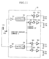
- the electric circuit shown in FIG. 11 is characterized by providing an adder 60 which receives a current command CP representing a pressure to press the roller 2 against the external equipment. This adder 60 adds the foregoing constant-current command C with the current command CP; and then, a result of addition is supplied to the adder 552.
- the operational result of the controller 53 is subtracted from the result of addition of the adder 60.
- the current command CP is further incorporated into the current flowing through the coils 137 and 138 which are located with respect to the X-axis direction in FIG. 8. Due to the addition of the current command CP, the pressure to press the roller 2 is provided as a offset value in advance.
- the pressure to press the roller 2 is provided as a offset value in advance.
- one sensor i.e., 14x or 14y
- one sensor is provided to detect the displacement of the shaft 1 in each of the X-axis direction and Y-axis direction.
- a sensor 14xx is provided at an opposite-side position of the sensor 14x with respect to the center of the shaft 1 (or origin), while a sensor 14yy is provided at an opposite-side position of the sensor 14y with respect to the center of the shaft 1.
- a differential amplifier 61 detects a difference between the outputs of the sensors 14x and 14xx so as to produce a differential output which is then supplied to the sensor amplifier 51.
- a differential amplifier 62 detects a difference between the outputs of the sensors 14y and 14yy so as to produce a differential output which is then supplied to the sensor amplifier 52. Due to the provision of the two sensors with respect to each axial direction, it is possible to double the sensitivity of detection for the amount of displacement of the shaft 1. Further, it is possible to cancel the noise of the sensor and the variation in the characteristic of the sensor, wherein such variation is caused due to the variation of the temperature. In short, it is possible to improve the precision for the measurement of the displacement of the shaft 1.
- FIG. 13 is a sectional view illustrating a mechanical structure of the rotating machine providing a vibration control device 300 according to a second embodiment of the present invention.
- FIG. 14 is a sectional view illustrating a main part of the rotating machine which is taken from the view of FIG. 13 with respect to line IA-IB. In order to avoid illustrating the complicated construction, the illustration of FIG. 14 is somewhat simplified by omitting some parts such as the rotor of the rotating machine 100.
- both-side edges of the shaft 103 are supported by the bearing stands through the ball bearings.
- the rotating machine 100 shown in FIG. 13 is characterized by providing the vibration control device 300 instead of the bearing stand 141.
- a numeral 202 denotes a secondary yoke having a cylindrical shape, through which the shaft 103 is inserted.
- An approximately half portion of the cylinder of the secondary yoke 202 supports the shaft 103 through the ball bearing B1, while another remaining portion is securely fixed to an edge portion of the body of the rotating machine by means of an elastic member 204 which is made by the rubber, metal spring and the like.
- a primary yoke 201 having an annulus-ring-like shape is provided to face with the secondary yoke 202, so that those two yokes are arranged in a concentric manner.
- the primary yoke 201 is attached to an interior wall of the body of the rotating machine.
- Eight magnetic poles are projected from an interior wall of the primary yoke 201 such that they are projected toward a peripheral surface of the secondary yoke 202.
- Those magnetic poles are respectively wound by coils LYa, LYb, LXa, LXb, LYc, LYd, LXc and LXd. Among those coils, only the coil LYa is shown in FIG. 13.
- the coils LYa and LYb are connected together in series or in parallel. By supplying electric currents to those coils, magnetic flux is formed and is passing through a magnetic path which sequentailly passes through the primary yoke 201, the magnetic pole wound by the coil LYb, the secondary yoke 202, the magnetic pole wound by the coil LYa and the primary yoke 201. Due to the magnetic flux relating to the coils LYa and LYb, the secondary yoke 202 is attracted toward the primary yoke 201 in a Y-axis direction.
- each pair of the coils among a pair of the coils LXa and LXb, a pair of the coils LYc and LYd and a pair of the coils LXc and LYd a pair of two coils and their magnetic poles function like an electromagnet by which the secondary yoke 202 is attracted toward by primary yoke 201 in a certain axial direction.
- a pair of the coils LYa and LYb and their magnetic poles are provided to form an electromagnet by which the secondary yoke 202 is attracted toward the primary yoke 201 in a (+Y)-axial direction.
- a pair of the coils LXa and LXb and their magnetic poles are provided to form an electromagnet by which the secondary yoke 202 is attracted in a (+X)-axial direction; a pair of the coils LYc and LYd and their magnetic poles are provided to form an electromagnet by which the secondary yoke 202 is attracted in a (-Y)-axial direction; and a pair of the coils LXc and LXd and their magnetic poles are provided to form an electromagnet by which the secondary yoke 202 is attracted in a (-X)-axial direction.
- eddy currents are occurred in the primary yoke 201 and the secondary yoke 202, so that those eddy currents may act like a disturbance for the secondary yoke 202.
- it is possible to reduce those eddy currents by re-designing each of the primary yoke 201 and the secondary yoke 202 in the laminated structure.
- a distance sensor 203X is provided in an X-axis direction between the primary yoke 201 and the secondary yoke 202, while another distance senor 203Y is provided in a Y-axis direction between the primary yoke 201 and the secondary yoke 202.
- the distance sensors 203X and 203Y detect X-axis distance and Y-axis distance respectively with respect to the secondary yoke 202 so as to produce distance signals respectively.
- only the distance sensor 203Y is shown in FIG. 13.
- the distance sensors 203X and 203Y it is possible to employ the eddy-current-type sensor, optical sensor and the like.
- the detection signals given from the distance sensors 203Y and 203X are supplied to the vibration control circuit 200 shown in FIG. 13.
- the vibration control circuit 200 is activated by the detection signal of the distance sensor 203X so as to eventually control the vibration in the X-axis direction.
- the vibration control circuit 200 is also activated by the detection signal of the distance sensor 203Y so as to eventually control the vibration in the Y-axis direction.
- Such axis-directional control for the vibration is performed by controlling electric currents flowing through the coils. By controlling those electric currents, the intensity of the magnetic flux to be produced by the coils is controlled.
- the vibration control circuit 200 controls amounts of the electric currents flowing through the coils LYa, LYb, LXa, LXb, LYc, LYd, LXc and LXd respectively.
- FIG. 15 is a circuit diagram showing a part of the vibration control circuit 200 which relates to a Y-axis control for the vibration of the secondary yoke 202.
- the detection signal given from the distance sensor 203Y is supplied to a controller 212Y through a sensor amplifier 211Y.
- the controller 212Y performs predetermined processing, containing the PID control processes, on an output signal of the sensor amplifier 211Y. Then, an output signal of the controller 212Y is delivered to an adder 221Y and a subtracter 222Y.
- the output signal of the controller 212Y contains three elements, i.e., a proportional element (P), an integrated element (I) and a differentiated element (D).
- the proportional element (P) is set at "0" under the state where shaft 103 is not vibrated so that the secondary yoke 202 is located at an ideal location. If the location of the secondary yoke 202 is deviated from the ideal location in the (+Y)-axial direction, the proportional element (P) has a negative value whose absolute value corresponds to an amount of (+Y)-axial displacement of the secondary yoke 202. In contrast, when the location of the secondary yoke 202 is deviated from the ideal location in the (-Y)-axial direction, the proportional element (P) has a positive value whose absolute value corresponds to an amount of (-Y)-axial displacement of the secondary yoke 202.
- Both of the proportional element (P) and integrated element (I) described above function as a control signal which controls the location of the secondary yoke 202 to be maintained at the predetermined location.
- the differentiated element (D) functions as a control signal which raises up a damping coefficient of the vibration of the rotating system.
- the adder 221Y adds the output signal of the controller 212Y to a constant-current command S.
- the subtracter 222Y subtracts the output signal of the controller 212Y from the constant-current command S.
- Output signals of the adder 221Y and the subtracter 222Y are supplied to power amplifiers 231Y and 232Y respectively.
- the power amplifier 231Y drives the coils LYa and LYb, while the power amplifier 232Y drives the coils LYc and LYd.
- the above-mentioned configuration of the circuit portion relates to the Y-axial vibration control.
- the vibration control circuit 200 further provides another circuit portion, having the same configuration, which relates to the X-axial vibration control. More specifically, another circuit portion controls the amount of electric currents to be flown through the coils LXa, LXb, LXc and LXd on the basis of the detection signal of the distance sensor 203X.
- an equal magnetic force is effected on the secondary yoke 202 in each of the (+Y)-axis direction, (+X)-axis direction, (-Y)-axis direction and (-X)-axis direction, so that the secondary yoke 202 is attracted by the equal force in each of those four directions.
- the location of the secondary yoke 202 is maintained at the ideal location.
- the large vibration may be easily produced on the shaft 103 in its traverse direction. If such vibration is produced, the vibration is transmitted to the secondary yoke 202 through the ball bearing B1.
- the vibration which is effected in the (+Y)-axis direction and (-Y)-axis direction is caused for the secondary yoke 202
- a positional displacement of the secondary yoke 202 is sensed by the distance sensor 203Y whose output signal is sent to the controller 212Y through the sensor amplifier 211Y.
- the controller 212Y produces a signal corresponding to the amount of the positional displacement of the secondary yoke 202.
- the proportional element (P) within the output signal of the controller 212Y has a negative value when the direction of the positional displacement of the secondary yoke 202 coincides with the (+Y)-axis direction. Due to the negative value of the proportional element (P), the amount of electric currents flowing through the coils LYa and LYb is reduced, while the amount of electric currents flowing through the coils LYc and LYd is increased. In contrast, when the direction of the positional displacement of the secondary yoke 202 coincides with the (-Y)-axis direction, the proportional element (P) has a positive value.
- the amount of electric currents flowing through the coils LYa and LYb is increased, while the amount of electric currents flowing through the coils LYc and LYd is reduced.
- the integrated element (I) accompanied with the proportional element (P) within the output signal of the controller 212Y is used to control the amount of electric currents to be flown through each of the coils, the location of the shaft 103 is controlled to be maintained at the predetermined location under the effects of the positional control of the secondary yoke 202.
- the differentiated element (D) contained in the output signal of the controller 212Y may contribute to the control of the amount of electric currents flowing through each coil at a certain phase-timing which is advanced from that of the proportional element (P).
- the differentiated element (D) achieves a function to increase the damping coefficient of the rotating system containing the shaft 103.
- the same thing can be said to the X-axial control of the vibration of the secondary yoke 202.
- the same vibration control which is effected in the Y-axis direction, is also effected in the X-axis direction on the basis of the detection signal given from the distance sensor 203X.
- a characteristic curve B in the graph shown in FIG. 4 represents a relationship between the number of revolution "N" and the amplitude of the roller 105 at its point "a" in the rotating machine providing the vibration control device according to the second embodiment.
- the characteristic curve B indicates that the amplitude of the vibration is reduced to an extremely low level at the number of revolution which is in the proximity of the first-order natural frequency.
Landscapes
- Engineering & Computer Science (AREA)
- General Engineering & Computer Science (AREA)
- Physics & Mathematics (AREA)
- Electromagnetism (AREA)
- Mechanical Engineering (AREA)
- Acoustics & Sound (AREA)
- Aviation & Aerospace Engineering (AREA)
- Power Engineering (AREA)
- Connection Of Motors, Electrical Generators, Mechanical Devices, And The Like (AREA)
- Magnetic Bearings And Hydrostatic Bearings (AREA)
Abstract

Description
- The present invention relates to a vibration control device which is suitable for use in a rotating machine such as a high-speed motor employed in textile machinery and the like.
- FIG. 1 is a sectional view illustrating a mechanical structure of a high-speed motor which has a general construction of the motor conventionally known and is especially used in the textile machine.
- The motor shown in FIG. 1 is a so-called outer-rotor motor, in which a
roller 2 having a hollow-cylinder-like shape rotates about ashaft 1 whose both sides are securely fixed. Herein, theroller 2 is equipped with theshaft 1 by means ofbearings 3 at both sides thereof such that theroller 2 can freely rotate about theshaft 1. - A
rotor core 5 is attached to an interior surface of theroller 2 through amagnet 4, while astator core 6 is attached to theshaft 1 to face with therotor core 5 through an air gap. Upon the receipt of electric currents carried from acable 7 which is introduced to thestator core 6 through a hollow portion of theshaft 1, a rotating magnetic field is produced around thestator core 6. - In short, the above-mentioned
magnet 4, therotor core 5 and thestator core 6 are assembled together to form a synchronous induction motor. Instead of the synchronous induction motor, it is possible to employ an induction motor. In the synchronous induction motor described above, theroller 2 rotates about theshaft 1. By pressing a hobbin winder against a peripheral face of theroller 2 which is rotating about theshaft 1, yarn is wound up. - Thus, a peripheral velocity of the
roller 2, which is rotating, becomes roughly proportional to a winding speed of the yarn. - Meanwhile, in these days, it is demanded to raise up the winding speed of the yarn for an improvement of the productivity in the textile industries. For this reason, a higher peripheral velocity is required for the
roller 2. For example, the peripheral velocity of 6,000 [m/min] or so is required for theroller 2. In order to achieve such high peripheral velocity, there are provided two methods as follows: - ① a first method to enlarge an outer diameter of the
roller 2; and - ② a second method to increase the number of revolution of the
roller 2. - However, the first method raises a new problem that the size of the
roller 2 must be enlarged as well as another problem that a higher precision should be required for the bearing 3 to respond to an increase of the weight of theroller 2. - Therefore, the second method is conventionally employed. In addition, the diameter of the
shaft 1 is reduced as well. Thus, it is possible to use the bearing which has a smaller maximum load and smaller major and minor diameters. - However, as the diameter of the
shaft 1 becomes smaller, a frequency of a natural vibration occurred on theshaft 1 should become lower. Under an effect of a large number of revolution of theroller 2, the above-mentioned natural vibration should be occurred when theroller 2 rotates at a certain number of revolution which is lower than the number of revolution corresponding to the peripheral velocity to be required. This may badly affect the operation of the motor. - Next, the natural vibration will be described in detail. In general, the natural vibration represents a mechanical characteristic which is inherently provided in the mechanical structure. When exciting the mechanical structure with its natural frequency, the resonance phenomenon is occurred, so that the mechanical structure should be vibrated with a very large vibration.
- Each of FIGS. 2A, 2B and 2C shows a manner of the natural vibration of the
shaft 1 in connection with each of vibration modes. As compared to theshaft 1, theroller 2 has a greater rigidity. Hence, as compared to theshaft 1, theroller 2 has a greater natural frequency. Therefore, when observing the motor as a whole, the natural vibration of theroller 2 can be neglected. Thus, it is possible to study the manner of vibration of the motor by referring to the natural vibration of theshaft 1 only. - It can be obviously observed from the drawing shown in FIG. 2A that no vibration is produced when the rotation of the
roller 2 is stopped. However, when starting the rotation of theroller 2, due to the vibration accompanied with the rotation of theroller 2, theshaft 1 should be excited in vibration. Thereafter, when the number of revolution of theroller 2 reaches 7,980 rpm as shown in FIG. 2B, a certain natural vibration (at frequency of 133 Hz) is produced on theshaft 1 whose both-side edges securely fixed act like nodes for the vibration. This manner of vibration will be represented by a term called "first-order vibration mode". In the case of the first-order vibration mode, theroller 2 as a whole should be largely vibrated up and down in accordance with the vibration of theshaft 1. - Thereafter, when the number of revolution of the
roller 2 is further increased to reach 16,080 rpm as shown in FIG. 2C, a split natural vibration (at frequency of 268 Hz) is produced on theshaft 1, in which the both-side edges of theshaft 1 and a mid-point therebetween act like the nodes for the vibration. This manner of vibration will be represented by a term called "second-order vibration mode". In the case of the second-order vibration mode, due to the vibration of theshaft 1, theroller 2 should be vibrated such that the both-side edges thereof vibrate by different phases which are reverse to each other. In short, theroller 2 vibrates like a seesaw. - Similarly, every time the number of revolution of the
roller 2 is increased by a certain number of revolution, the split natural vibration is produced on theshaft 1 by using its both-side edges and other points as the nodes for the vibration. Each of the other points is located for each of equally divided parts which are disposed between the both-side edges of theshaft 1. Herein, the number of the equally divided parts is set as an integral number which is equal to or higher than "1". The manner of such high-order vibration will be represented by a term called "n-order vibration mode". Incidentally, as the integer "n" becomes higher, it becomes not possible to neglect the natural vibration of an element other than theshaft 1. - When the natural vibration is produced on the
shaft 1 as described above, theroller 2 is correspondingly vibrated. In the textile machine, such vibration is transmitted to the hobbin winder. This results in a lower quality of the yarn to be wound. Due to the natural vibration of theshaft 1, therotor core 5 may come in touch with the stator core 6 (see FIG. 1), which causes a possibility that the electric motor itself will be damaged. - FIG. 3 is a sectional view illustrating a mechanical construction of a rotating
machine 101 equipped with an overhang roller, which is applied to the textile machine used for spinning cotton into thread and the like. FIG. 3 shows a view of an inner structure of therotating machine 101 whose one-side portion from an axial line J is cut out. As shown in FIG. 3, a body of therotating machine 101 is fixed with anequipment 102 which is an object to be driven by therotating machine 101. Anumeral 103 denotes a shaft which works as a rotating axis for therotating machine 101. Thisshaft 103 is inserted through the body of the rotatingmachine 101 and is surrounded by arotor 106. Astator 107 is further provided in an inside of the body of therotating machine 101 such that thestator 107 surrounds around arotor 106. Thisstator 107 produces a magnetic field to drive a rotation of therotor 106. One end of theshaft 103 is supported by abearing stand 141, provided at an edge portion of the body of the rotatingmachine 101, through a ball bearing B1. An intermediate portion and another end portion of theshaft 103 is supported by abearing stand 142 through a ball bearing B2. Theshaft 103 protrudes from the bearing stand 142 toward the outside of the rotatingmachine 101. Aroller 105 is attached to the protruding end portion of theshaft 103. Therotating machine 101 creates a rotation-driving force, which is transmitted through theroller 105 toward theequipment 102 to be driven. - In the above-mentioned
rotating machine 101, under effects of the magnetic field produced by thestator 107, a rotating force is imparted to therotor 106. This rotating force is transmitted to theroller 105 through theshaft 103. In the process of spinning cotton into thread and the like, theroller 105 which is driven to be rotated functions to impart some tension to the thread or functions to guide the thread in a predetermined course. - In order to cope with the demand to improve the productivity, the roller of the rotating machine tends to be enlarged in size. However, when enlarging the size of the roller, an axial-edge load and an axial-edge mass applied to the rotating machine should be increased. This may cause a greater amount of imbalance in the rotating system containing the roller in the rotating machine. Based on such amount of imbalance, a greater vibration should be caused in the rotating machine. Such phenomenon to cause the vibration due to the imbalance of the rotating system will be described in detail by referring to FIGS. 4 to 6.
- In order to avoid the vibration of the rotating system, an element to cause the vibration should be removed from the construction of the rotating system, and the amount of imbalance of the rotation should also be eliminated. Actually, however, it is difficult to form each of parts (e.g., rotor) of the rotating system perfectly in a axis-symmetrical shape; in other words, it is very difficult to arrange those parts in the rotating system perfectly in an axis-symmetrical manner. For this reason, there must be provided a small deviation between the center of gravity and the rotation axis in the rotating system. When the rotating body in which the center of gravity is deviated from the rotation axis is driven to be rotated, a vibration having a frequency which corresponds to a rotation speed is inevitable caused in the rotating body. Other than the deviation of the center of gravity, there exists several kinds of elements which distribute to the amount of imbalance in the rotating system. Such amount of imbalance causes an excitation force in the rotating system, so that a certain vibration is excited in the rotating system.
- FIG. 4 is a graph showing a characteristic of the vibration which is produced in the rotating system due to the above-mentioned amount of imbalance. In FIG. 4, a characteristic curve A represents a relationship between a number of revolution "N" and an amplitude of the vibration at a point "a" of the
roller 105 in the case where therotating machine 101 is driven to be rotated. In general, the rotating system, which is constructed by the roller, shaft and the like, has a natural frequency of a natural vibration. Under the state where the number of revolution of therotating machine 101 is lower than the natural frequency, the rotating system is hardly affected by the excitation force which is caused due to the amount of imbalance. Therefore, as shown in FIG. 4, only a small vibration having a small amplitude is imparted to therotor 105. Thus, it is possible to obtain a proper rotation in which an excessive bending stress is not imparted to the shaft as shown in FIG. 5. - However, when the number of revolution of the
rotating machine 101 becomes closer to the natural frequency, the rotating system sensitively responds to the excitation force to be created due to the amount of imbalance, so that a big vibration should be occurred in the roller and the like. FIG. 4 indicates that the amplitude of the vibration at the point "a" of theroller 105 is raised up to the maximum when the number of revolution reaches a frequency N1 of first-order natural vibration (hereinafter, denoted to as a first-order natural frequency N1). Actually, there are existed second-order and other higher-order natural vibrations; however, those high-order natural vibrations are omitted in the graph of FIG. 4. When the above-mentioned big vibration is occurred in theroller 105, a relatively big stress is imparted to theshaft 103. In the worst case, theshaft 103 is bent as shown in FIG. 6, which causes an extremely dangerous state for the rotating machine. Incidentally, a bending manner of theshaft 103 is somewhat exaggerated in FIG. 6 as compared to the actual bending manner. - In order to prevent the big vibration from being produced in the rotating system, a rated number of revolution "NMAX" of the rotating machine is generally set lower than the first-order natural frequency N1.
- However, in order to raise up the productivity, the rated number of revolution should be set higher. In order to do so, two countermeasures are required as follows:
- ① to increase the first-order natural frequency; and
- ② to reduce the amplitude of the vibration which is caused when the number of revolution coincides with the natural frequency.
- In order to increase the first-order natural frequency, the diameter of the
shaft 103 should be enlarged. However, when enlarging the diameter of theshaft 103, a so-called "dn value" of the ball bearing supporting theshaft 103 must be also increased, which will result in a reduction of the lifetime of the ball bearing. For this reason, there is a limitation to enlarge the diameter of the shaft. - Meanwhile, when the vibration having the first-order natural frequency N1 is occurred in the roller, the amplitude of the vibration is determined by the amount of imbalance and a damping coefficient which is provided for the rotating system. Therefore, a degree of stability of the rotation can be raised up by reducing the amount of imbalance; or the damping coefficient can be also increased. Actually, however, there is a limitation to do so. In short, it is difficult to control (or reduce) the vibration of the roller at the first-order natural frequency.
- It is accordingly a primary object of the present invention to provide a vibration control device which is capable of remarkably reducing an amplitude of the natural vibration which is inevitably caused by the rotation of the electric motor.
- It is another object of the present invention to provide a vibration control device which is capable of preventing a big vibration from being occurred in the rotating machine even when the number of revolution coincides with the natural frequency of the rotating system.
- The vibration control device according to the present invention can be applied to the rotating machine in which a primary yoke is provided within a hollow space of a secondary yoke so that the secondary yoke rotates about a shaft inserted through the primary yoke. According to the fundamental configuration of the present invention, the vibration control device comprises a plurality of electromagnet portions, a pair of sensors and a control portion. The above-mentioned electromagnet portions are arranged around a peripheral surface of the primary yoke, and they at least provide a pair of first and second electromagnet portions and another pair of third and fourth electromagnet portions. Herein, the first electromagnet portion is arranged opposite to the second electromagnet portion with respect to an X-axis direction crossing a sectional area of the primary yoke, while the third electromagnet portion is arranged opposite to the fourth electromagnet portion with respect to a Y-axis direction which is perpendicular to the X-axis direction. One sensor detects a positional displacement between the primary and secondary yokes with respect to the X-axis direction on the basis of a first reference value which is determined in advance. Another sensor detects a positional displacement between the primary and secondary yokes with respect to the Y-axis direction on the basis of a second reference value which is determined in advance.
- In the above-mentioned configuration of the vibration control device, the positional displacement detected by one sensor is controlled to be reduced by controlling electric currents supplied to the first and second electromagnet portions, while the positional displacement detected by another sensor is controlled to be reduced by controlling electric currents supplied to the third and fourth electromagnet portions. By electromagnetically controlling the positional displacement between the primary and secondary yokes with respect to each of the axial directions, the vibration of the shaft is eventually reduced. Hence, the rotating machine can perform a smooth rotation.
- Incidentally, the vibration control device according to the present invention can be also applied to another rotating machine in which a secondary yoke is provided within a hollow space of the primary yoke and a shaft is inserted through the secondary yoke so that the secondary yoke rotates together with the shaft within the primary yoke, wherein electromagnet portions are arranged around an interior wall of the primary yoke.
- Further objects and advantages of the present invention will be apparent from the following description, reference being had to the accompanying drawings wherein the preferred embodiments of the present invention are clearly shown.
- In the drawings:
- FIG. 1 is a sectional view illustrating the mechanical structure of the high-speed motor;
- FIGS. 2A to 2C are drawings each showing a manner of vibration of the motor in connection with the number of revolution;
- FIG. 3 is a sectional view showing a part of the mechanical structure of the rotating machine;
- FIG. 4 is a graph showing a relationship between the number of revolution and the vibration occurred at the roller of the rotating machine;
- FIG. 5 is a drawing showing a behavior of the rotating machine under the state where the number of revolution does not coincide with the natural frequency of the natural vibration occurred in the rotating machine;
- FIG. 6 is a drawing showing a behavior of the rotating machine under the state where the number of revolution coincides with the natural frequency of the rotating machine;
- FIG. 7 is a sectional view showing a mechanical structure of the motor providing the vibration control device according to a first embodiment of the present invention;
- FIG. 8 is a sectional view of a main part of the motor which is take from the view of FIG. 7 with respect to line A1-A2;
- FIG. 9 is a block diagram showing an electric configuration of the first embodiment;
- FIG. 10 is a graph showing a relationship between the number of revolution of the roller and the amplitude of the vibration;
- FIG. 11 is a block diagram showing a modified example of the first embodiment;
- FIG. 12 is a block diagram showing another modified example of the first embodiment;
- FIG. 13 is a sectional view of the rotating machine providing a vibration control device according to a second embodiment of the present invention;
- FIG. 14 is a sectional view of a main part of the rotating machine which is taken from the view of FIG. 13 with respect to line IA-IB;
- FIG. 15 is a circuit diagram showing a part of a vibration control circuit in connection with a Y-axial control for the vibration; and
- FIG. 16 is a sectional view of the rotating machine according to a modified example of the second embodiment of the present invention.
- Next, the preferred embodiments of the present invention will be described.
- Next, a first embodiment of the present invention will be described. FIG. 7 is a sectional view showing a mechanical structure of the high-speed motor. As compared to the foregoing motor shown in FIG. 1, this motor shown in FIG. 7 is characterized by providing a
vibration control device 10. Thisvibration control device 10 is constructed by aprimary yoke 11, asecondary yoke 12, acoil 13, asensor 14 and adrive circuit 15. In FIG. 7, parts identical to those shown in FIG. 1 will be designated by the same numerals; hence, description thereof will be omitted. - FIG. 8 is a sectional view of a certain part of the motor, which is taken from the view of FIG. 7 with respect to line A1-A2.
- In FIG. 8, the
shaft 1 is attached with theprimary yoke 11 providing eightmagnetic poles 11₁ to 11₈ which are arranged in a radial manner. Thosemagnetic poles 11₁ to 11₈ are wound bycoils 13₁ to 13₈ respectively. - Among those coils, each two coils are electrically connected together in series or in parallel. For example, the
coils coils coils coils - Meanwhile, the
secondary yoke 12 are attached along the interior surface of theroller 2 such that thesecondary yoke 12 faces with themagnetic poles 11₁ to 11₈. If theroller 2 is made by using the magnetic materials, thesecondary yoke 12 can be omitted. Further, if the eddy-current loss is relatively large, it is required to re-design the structures of theprimary yoke 11 and thesecondary yoke 12. In such case, by employing a laminated structure for each of theprimary yoke 11 and thesecondary yoke 12, it is possible to reduce the eddy-current loss. - When applying electric currents to the
coils 13₁ to 13₈, themagnetic poles 11₁ to 11₈ and thesecondary yoke 12 are subjected to electromagnetic forces which are indicated by dotted lines in FIG. 8. Each of those dotted lines represents the line of magnetic force. In short, the magnetic poles are attracted to thesecondary yoke 12. - A
sensor 14x senses a displacement of an air gap dx in an X-axis direction. The air gap dx is provided between theprimary yoke 11 and thesecondary yoke 12. The displacement of the air gap dx is sensed by referring to a reference value which is set in advance with respect to the air gap dx. Hence, thesensor 14x senses a direction of displacement and an amount of displacement in the X-axis direction with respect to the air gap dx. For example, when the air gap becomes smaller, thesensor 14x outputs the amount of displacement with a negative sign (-). On the other hand, when the air gap becomes larger, thesensor 14x outputs the amount of displacement with a positive sign (+). Anothersensor 14y senses a displacement of an air gap dy, provided between theprimary yoke 11 and thesecondary yoke 12, in a Y-axis direction. The displacement of the air gap dy is sensed by referring to a reference value which is set in advance with respect to the air gap dy. Hence, thesensor 14y senses a direction of displacement and an amount of displacement in the Y-axis direction with respect to the air gap dy. - Next, an electric configuration of the first embodiment will be described. Particularly, an electric circuit containing the
sensors drive circuit 15 and thecoils 13₁ to 13₈ will be described in detail by referring to FIG. 9. In FIG. 9, parts identical to those shown in FIG. 8 will be designated by the same numerals. - As shown in FIG. 9, a result of the detection obtained by the
sensor 14x is subjected to amplification performed by asensor amplifier 51; and then, an output of thesensor amplifier 51 is supplied to acontroller 53. Thiscontroller 53 performs an appropriate operational process on the result of detection of thesensor 14x. For example, a so-called PID operational processes (wherein a term "PID" means Proportional operation, Integration and Differentiation) is effected by thecontroller 53. An operational result of thecontroller 53 is supplied to a first input (+) of anadder 55₁ as well as a first input (-) of anadder 55₂. On the other hand, a constant-current command C is supplied to second inputs of theadders - The
adder 55₁ adds the constant-current command C to the operational result of thecontroller 53; and then, a result of addition is subjected to current amplification performed by apower amplifier 57₁. Then, an output of thepower amplifier 57₁ is supplied to thecoils - On the other hand, the
adder 55₂ performs a subtraction by which the operational result of thecontroller 53 is subtracted from the constant-current command C; and then, a result of subtraction is subjected to current amplification performed by apower amplifier 57₂. Then, an output of thepower amplifier 57₂ is supplied to thecoils power amplifiers - A result of detection of another
sensor 14y is subjected to same operational processes which are performed with respect to the result of detection of thesensor 14x. More specifically, the result of detection of thesensor 14y is amplified by asensor amplifier 52, the output of which is then subjected to PID operational process performed by acontroller 54. Anadder 56₁ adds the constant-current command C to the output of thecontroller 54. A result of addition of theadder 56₁ is subjected to current amplification by apower amplifier 58₁, the output of which is then supplied to thecoils controller 54 is subtracted from the constant-current command C by anotheradder 56₂. An output of theadder 56₂ is subjected to current amplification performed by apower amplifier 58₂, the output of which is then supplied to thecoils - Next, operations of the first embodiment will be described.
- At first, when the rotation of the
roller 2 is stopped, or when the vibration accompanied with the rotation of theroller 2 is too small and is negligible, the air gaps dx and dy between theprimary yoke 11 and thesecondary yoke 12 are set at their reference values. Hence, output levels of thesensors controllers adders coils 13₁ to 13₈. Thus, the attraction force imparted between thecoils secondary yoke 12 is canceled by the attraction force imparted between thecoils secondary yoke 12. Similarly, the attraction force imparted between thecoils secondary yoke 12 is canceled by the attraction force imparted between thecoils secondary yoke 12. In short, the attraction force imparted to the certain coil is balanced with the attraction force imparted to its opposite coil in both of the X-axis direction and Y-axis direction. As a result, the air gaps dx and dy are maintained at their reference values respectively. - Next, the operations of the first embodiment will be described by referring to the state where the vibration of the
shaft 1 is excited by the rotation of theroller 2 so that theshaft 1 is subjected to displacement in a certain direction by which the air gap dx is made larger. - In the above-mentioned state, the
sensor 14x outputs the amount of displacement with the positive sign (+) on the basis of the reference value. Hence, the operational result of thecontroller 53 responds to the positive amount of displacement of the air gap dx. In this case, theadder 55₁ produces a signal representing the result of the addition in which the operational result of thecontroller 53 is added with the constant-current command C. Based on the signal outputted from theadder 55₁, the attraction force produced by thecoils adder 55₂ produces a signal representing the result of subtraction in which the operational result of thecontroller 53 is subtracted from the constant-current command C, so that the attraction force produced by thecoils - Due to an imbalance between the attraction force produced by the
coils coils primary yoke 11 is moved in a positive direction (+) of X axis (i.e., a right-side direction in FIG. 8) within thesecondary yoke 12. As described before, the rigidity of theroller 2 is made higher than the rigidity of theshaft 1. Hence, the aforementioned displacement of theshaft 1, which is effected such that the air gap dx is made larger, is canceled by the above-mentioned imbalance of the attraction force by which the air gap dx is made smaller. - In contrast, when the vibration of the
shaft 1 is excited by the rotation of theroller 2 so that the displacement of theshaft 1 is caused in a direction by which the air gap dx is made smaller, thesensor 14x outputs the amount of displacement with the negative sign (-) on the basis of the reference value. In this case, theadder 55₁ eventually performs a subtraction in which an absolute value of the operational result of thecontroller 53 is subtracted from the constant-current command C, so that the attraction force produced by thecoils adder 55₂ eventually performs an addition in which the absolute value of the operational result of thecontroller 53 is added to the constant-current command C, so that the attraction force produced by thecoils - Due to an imbalance between the attraction force produced by the
coils coils primary yoke 11 is moved in a negative direction (-) of X axis (i.e., a left-side direction in FIG. 8) within thesecondary yoke 12. Hence, the aforementioned displacement of theshaft 1, which is effected such that the air gap dx is made smaller, is canceled by the above-mentioned imbalance of the attraction force by which the air gap dx is made larger. - In short, there is formed a feedback loop which can be described as follows:
sensor 14x →drive circuit 15 → attraction force ofcoils coils sensor 14x (which detects the displacement), wherein an arrow "→" represents a direction in which a state of a former element affects a state of a latter element. Since the above-mentioned feedback loop is established in the X-axis direction, a positional relationship between theshaft 1 and theroller 2 is controlled such that the air gap dx is normally maintained at the reference value. - Similar control is performed with respect to the Y-axis direction as well. In short, there is formed a feedback loop which is established in the Y-axis direction and is described as follows:
sensor 14y →drive circuit 15 → attraction force ofcoils coils sensor 14y (which detects the displacement). Due to the above-mentioned feedback loop in the Y-axis direction, the positional relationship between theshaft 1 and theroller 2 is controlled such that the air gap dy is normally maintained at the reference value. - The first embodiment described heretofore is characterized by providing a displacement control independently for each of the X-axis direction and the Y-axis direction. Therefore, in a whole area of the rotation as shown in FIG. 8, the air gaps dx and dy formed between the
primary yoke 11 and thesecondary yoke 12 are controlled to be maintained at their reference values. Thus, even if the natural vibration of theshaft 1 is excited by the rotation of theroller 2 so that a level of the amplitude of the natural vibration reaches a peak level, it is possible to control the amplitude to be extremely small. - FIG. 10 is a graph showing a relationship between the number of revolution of the
roller 2 and the amplitude of the vibration at the point "a" (indicating an edge point of the peripheral surface of theroller 2 shown in FIG. 2A). As shown in this graph, in the conventional motor, the natural vibrations sequentially occur as the number of revolution of theroller 2 becomes larger; thus, the amplitude of the vibration at the point "a" reaches a peak level twice at 7,980 [rpm] and 16,080 [rpm]. - Even in the motor providing the vibration control device according to the first embodiment, as similar to the conventional motor, the natural vibration may occur as the number of revolution of the
roller 2 becomes larger. However, it is observed from the graph (see dotted line) that the peak level of the amplitude of the vibration can be reduced smaller as compared to that of the conventional motor under effects of the vibration control device. - Therefore, the motor providing the vibration control device according to the first embodiment can suppress the vibration to be smaller within the whole range of the numbers of revolution up to the substantially maximum number of revolution. Thus, it is not required for the motor to avoid the certain range of the numbers of revolution which cause the natural vibrations. In other words, the motor providing the present device can arbitrarily use any range of the numbers of revolution.
- In the description of the first embodiment, positions to locate the
primary yoke 11 and thesecondary yoke 12 are not described specifically. In order to obtain the largest effect in the suppression of a particular vibration node of the natural vibration of theshaft 1, it is obvious for us to locate a vibration control device at the position corresponding to that vibration mode to be suppressed (e.g. at an anti-node). - Since the present device can be built in the inside of the motor, it is not required to provide any external space for the device.
- In the electric circuit shown in FIG. 9, the operational result corresponding to the amount of displacement in each axial direction is added to or subtracted from the same constant-current command C. However, in order to cope with the situation where the
roller 2 is pressed against the external equipment in the X-axis direction (see FIG. 8) to transmit the rotation force to it, the electric circuit can be re-designed as shown in FIG. 11. As compared to the electric circuit shown in FIG. 9, the electric circuit shown in FIG. 11 is characterized by providing anadder 60 which receives a current command CP representing a pressure to press theroller 2 against the external equipment. Thisadder 60 adds the foregoing constant-current command C with the current command CP; and then, a result of addition is supplied to theadder 55₂. In theadder 55₂, the operational result of thecontroller 53 is subtracted from the result of addition of theadder 60. Thus, the current command CP is further incorporated into the current flowing through thecoils roller 2 is provided as a offset value in advance. Thus, when the peripheral surface of theroller 2 is pressed to the hobbin winder, it is possible to reduce the load to be imparted to thebearing 3, or it is possible to arbitrarily alter the spring constant at a moment when pressing theroller 2 to the hobbin winder. - In the first embodiment, one sensor (i.e., 14x or 14y) is provided to detect the displacement of the
shaft 1 in each of the X-axis direction and Y-axis direction. However, it is possible to provide a pair of sensors with respect to each axial direction as shown in FIG. 12. Herein, a sensor 14xx is provided at an opposite-side position of thesensor 14x with respect to the center of the shaft 1 (or origin), while a sensor 14yy is provided at an opposite-side position of thesensor 14y with respect to the center of theshaft 1. Adifferential amplifier 61 detects a difference between the outputs of thesensors 14x and 14xx so as to produce a differential output which is then supplied to thesensor amplifier 51. Similarly, adifferential amplifier 62 detects a difference between the outputs of thesensors 14y and 14yy so as to produce a differential output which is then supplied to thesensor amplifier 52. Due to the provision of the two sensors with respect to each axial direction, it is possible to double the sensitivity of detection for the amount of displacement of theshaft 1. Further, it is possible to cancel the noise of the sensor and the variation in the characteristic of the sensor, wherein such variation is caused due to the variation of the temperature. In short, it is possible to improve the precision for the measurement of the displacement of theshaft 1. -
- FIG. 13 is a sectional view illustrating a mechanical structure of the rotating machine providing a
vibration control device 300 according to a second embodiment of the present invention. FIG. 14 is a sectional view illustrating a main part of the rotating machine which is taken from the view of FIG. 13 with respect to line IA-IB. In order to avoid illustrating the complicated construction, the illustration of FIG. 14 is somewhat simplified by omitting some parts such as the rotor of therotating machine 100. - In the conventional rotating machine as shown in FIG. 3, both-side edges of the
shaft 103 are supported by the bearing stands through the ball bearings. As compared to such construction of the conventional rotating machine, the rotatingmachine 100 shown in FIG. 13 is characterized by providing thevibration control device 300 instead of thebearing stand 141. - In FIGS. 13 and 14, a numeral 202 denotes a secondary yoke having a cylindrical shape, through which the
shaft 103 is inserted. An approximately half portion of the cylinder of thesecondary yoke 202 supports theshaft 103 through the ball bearing B1, while another remaining portion is securely fixed to an edge portion of the body of the rotating machine by means of anelastic member 204 which is made by the rubber, metal spring and the like. - A
primary yoke 201 having an annulus-ring-like shape is provided to face with thesecondary yoke 202, so that those two yokes are arranged in a concentric manner. Theprimary yoke 201 is attached to an interior wall of the body of the rotating machine. Eight magnetic poles are projected from an interior wall of theprimary yoke 201 such that they are projected toward a peripheral surface of thesecondary yoke 202. Those magnetic poles are respectively wound by coils LYa, LYb, LXa, LXb, LYc, LYd, LXc and LXd. Among those coils, only the coil LYa is shown in FIG. 13. - The coils LYa and LYb are connected together in series or in parallel. By supplying electric currents to those coils, magnetic flux is formed and is passing through a magnetic path which sequentailly passes through the
primary yoke 201, the magnetic pole wound by the coil LYb, thesecondary yoke 202, the magnetic pole wound by the coil LYa and theprimary yoke 201. Due to the magnetic flux relating to the coils LYa and LYb, thesecondary yoke 202 is attracted toward theprimary yoke 201 in a Y-axis direction. The same thing can be said to each pair of the coils among a pair of the coils LXa and LXb, a pair of the coils LYc and LYd and a pair of the coils LXc and LYd. In short, a pair of two coils and their magnetic poles function like an electromagnet by which thesecondary yoke 202 is attracted toward byprimary yoke 201 in a certain axial direction. A pair of the coils LYa and LYb and their magnetic poles are provided to form an electromagnet by which thesecondary yoke 202 is attracted toward theprimary yoke 201 in a (+Y)-axial direction. Similarly, a pair of the coils LXa and LXb and their magnetic poles are provided to form an electromagnet by which thesecondary yoke 202 is attracted in a (+X)-axial direction; a pair of the coils LYc and LYd and their magnetic poles are provided to form an electromagnet by which thesecondary yoke 202 is attracted in a (-Y)-axial direction; and a pair of the coils LXc and LXd and their magnetic poles are provided to form an electromagnet by which thesecondary yoke 202 is attracted in a (-X)-axial direction. In some cases, eddy currents are occurred in theprimary yoke 201 and thesecondary yoke 202, so that those eddy currents may act like a disturbance for thesecondary yoke 202. In the case where the effects of those eddy currents cannot be overlooked, it is possible to reduce those eddy currents by re-designing each of theprimary yoke 201 and thesecondary yoke 202 in the laminated structure. - Meanwhile, a
distance sensor 203X is provided in an X-axis direction between theprimary yoke 201 and thesecondary yoke 202, while anotherdistance senor 203Y is provided in a Y-axis direction between theprimary yoke 201 and thesecondary yoke 202. Thedistance sensors secondary yoke 202 so as to produce distance signals respectively. Among those distance sensors, only thedistance sensor 203Y is shown in FIG. 13. As thedistance sensors - The detection signals given from the
distance sensors vibration control circuit 200 shown in FIG. 13. Thevibration control circuit 200 is activated by the detection signal of thedistance sensor 203X so as to eventually control the vibration in the X-axis direction. Similarly, thevibration control circuit 200 is also activated by the detection signal of thedistance sensor 203Y so as to eventually control the vibration in the Y-axis direction. Such axis-directional control for the vibration is performed by controlling electric currents flowing through the coils. By controlling those electric currents, the intensity of the magnetic flux to be produced by the coils is controlled. In the present embodiment, thevibration control circuit 200 controls amounts of the electric currents flowing through the coils LYa, LYb, LXa, LXb, LYc, LYd, LXc and LXd respectively. - FIG. 15 is a circuit diagram showing a part of the
vibration control circuit 200 which relates to a Y-axis control for the vibration of thesecondary yoke 202. In FIG. 15, the detection signal given from thedistance sensor 203Y is supplied to acontroller 212Y through asensor amplifier 211Y. Thecontroller 212Y performs predetermined processing, containing the PID control processes, on an output signal of thesensor amplifier 211Y. Then, an output signal of thecontroller 212Y is delivered to anadder 221Y and asubtracter 222Y. The output signal of thecontroller 212Y contains three elements, i.e., a proportional element (P), an integrated element (I) and a differentiated element (D). Among them, the proportional element (P) is set at "0" under the state whereshaft 103 is not vibrated so that thesecondary yoke 202 is located at an ideal location. If the location of thesecondary yoke 202 is deviated from the ideal location in the (+Y)-axial direction, the proportional element (P) has a negative value whose absolute value corresponds to an amount of (+Y)-axial displacement of thesecondary yoke 202. In contrast, when the location of thesecondary yoke 202 is deviated from the ideal location in the (-Y)-axial direction, the proportional element (P) has a positive value whose absolute value corresponds to an amount of (-Y)-axial displacement of thesecondary yoke 202. Both of the proportional element (P) and integrated element (I) described above function as a control signal which controls the location of thesecondary yoke 202 to be maintained at the predetermined location. The differentiated element (D) functions as a control signal which raises up a damping coefficient of the vibration of the rotating system. Theadder 221Y adds the output signal of thecontroller 212Y to a constant-current command S. Thesubtracter 222Y subtracts the output signal of thecontroller 212Y from the constant-current command S. Output signals of theadder 221Y and thesubtracter 222Y are supplied topower amplifiers power amplifier 231Y drives the coils LYa and LYb, while thepower amplifier 232Y drives the coils LYc and LYd. - The above-mentioned configuration of the circuit portion relates to the Y-axial vibration control. The
vibration control circuit 200 further provides another circuit portion, having the same configuration, which relates to the X-axial vibration control. More specifically, another circuit portion controls the amount of electric currents to be flown through the coils LXa, LXb, LXc and LXd on the basis of the detection signal of thedistance sensor 203X. - Next, operations of the second embodiment will be described in detail. Under the effect of the magnetic field produced by the
stator 107, therotor 106 is driven to be rotated, so that theshaft 103 is rotated. Now, when the number of revolution of therotating machine 101 is lower than the first-order natural frequency and any large vibration is not occurred on theshaft 103 so that thesecondary yoke 202 is located at the ideal location described before, the output signal of thecontroller 212Y is set at a zero level. In this situation, the electric current corresponding to the constant-current command S flows through each of the coils. Hence, an equal magnetic force is effected on thesecondary yoke 202 in each of the (+Y)-axis direction, (+X)-axis direction, (-Y)-axis direction and (-X)-axis direction, so that thesecondary yoke 202 is attracted by the equal force in each of those four directions. Thus, the location of thesecondary yoke 202 is maintained at the ideal location. - On the other hand, when the number of revolution of the
rotating machine 101 is close to the natural frequency, the large vibration may be easily produced on theshaft 103 in its traverse direction. If such vibration is produced, the vibration is transmitted to thesecondary yoke 202 through the ball bearing B1. For example, if the vibration which is effected in the (+Y)-axis direction and (-Y)-axis direction is caused for thesecondary yoke 202, a positional displacement of thesecondary yoke 202 is sensed by thedistance sensor 203Y whose output signal is sent to thecontroller 212Y through thesensor amplifier 211Y. Thus, thecontroller 212Y produces a signal corresponding to the amount of the positional displacement of thesecondary yoke 202. Herein, the proportional element (P) within the output signal of thecontroller 212Y has a negative value when the direction of the positional displacement of thesecondary yoke 202 coincides with the (+Y)-axis direction. Due to the negative value of the proportional element (P), the amount of electric currents flowing through the coils LYa and LYb is reduced, while the amount of electric currents flowing through the coils LYc and LYd is increased. In contrast, when the direction of the positional displacement of thesecondary yoke 202 coincides with the (-Y)-axis direction, the proportional element (P) has a positive value. Hence, the amount of electric currents flowing through the coils LYa and LYb is increased, while the amount of electric currents flowing through the coils LYc and LYd is reduced. Since the integrated element (I) accompanied with the proportional element (P) within the output signal of thecontroller 212Y is used to control the amount of electric currents to be flown through each of the coils, the location of theshaft 103 is controlled to be maintained at the predetermined location under the effects of the positional control of thesecondary yoke 202. Incidentally, the differentiated element (D) contained in the output signal of thecontroller 212Y may contribute to the control of the amount of electric currents flowing through each coil at a certain phase-timing which is advanced from that of the proportional element (P). In short, the differentiated element (D) achieves a function to increase the damping coefficient of the rotating system containing theshaft 103. The same thing can be said to the X-axial control of the vibration of thesecondary yoke 202. In this case, the same vibration control, which is effected in the Y-axis direction, is also effected in the X-axis direction on the basis of the detection signal given from thedistance sensor 203X. - According to the operations of the vibration control device described above, even if the number of revolution of the rotating machine coincides with the natural frequency so that the
shaft 103 is set in the situation where a large vibration is easily produced, it is possible to effectively reduce the vibration; hence, the operations of the rotating machine can be set in a stabilized state where the amplitude of the vibration is reduced. A characteristic curve B in the graph shown in FIG. 4 represents a relationship between the number of revolution "N" and the amplitude of theroller 105 at its point "a" in the rotating machine providing the vibration control device according to the second embodiment. As compared to the characteristic curve A corresponding to the conventional rotating machine which does not provide the vibration control device, the characteristic curve B indicates that the amplitude of the vibration is reduced to an extremely low level at the number of revolution which is in the proximity of the first-order natural frequency. - Next, modified examples of the second embodiment will be described respectively.
- (1) The second embodiment described above provides one distance sensor with respect to each of the X-axis direction and Y-axis direction. However, it is possible to provide two distance sensors with respect to each of the axial directions. As for the Y-axis direction, one sensor detects the positional displacement of the secondary yoke in the (+Y)-axis direction, while another sensor detects the positional displacement of the secondary yoke in the (-Y)-axis direction. Thus, outputs of the two sensors can be obtained with respect to each axial direction. Those two outputs are subjected to differential amplification effected by a differential amplifier, the output of which is then used to control the vibration. In this modified example, the sensitivity can be doubled with respect to the detection for the positional displacement of the secondary yoke. In addition, it is possible to eliminate the noise signals, having the same phase, which are occurred in the sensors and amplifiers due to the variation of the temperature and the like. In short, the modified example can contribute to the improvement of the precision for the measurement of the positional displacement of the secondary yoke.
- (2) In the second embodiment, the constant-level electric currents are supplied to each of the coils in response to the constant-current command; and in response to the variation of the positional displacement of the location of the
secondary yoke 202 which is deviated from the ideal location, the amount of electric currents supplied to one electromagnet is increased from the constant level of electric currents set by the constant-current command, while the amount of electric currents supplied to another electromagnet is decreased from the constant level of electric currents. In short, the second embodiment controls the amount of electric currents flowing through each of the coils on the basis of the constant level of electric currents set by the constant-current command. However, the second embodiment can be modified such that the amount of electric currents supplied to the electromagnet is directly controlled without using the constant-level electric currents. For example, the second embodiment is modified such that when a certain positional displacement is occurred in thesecondary yoke 202, the location of thesecondary yoke 202 is returned to its original location by supplying the electric currents to one electromagnet only. More specifically, when thesecondary yoke 202 is subjected to positional displacement in the (+Y)-axis direction so that the signal having the negative value is obtained from thecontroller 212Y, the electric currents corresponding to that signal are supplied to the coils LYc and LYd only. On the other hand, when thesecondary yoke 202 is subjected to positional displacement in the (-Y)-axis direction so that the signal having the positive value is obtained from thecontroller 212Y, the electric currents corresponding to that signal are supplied to the coils LYa and LYb only. This modified example can be realized by re-designing the circuit shown in FIG. 15 such that theadder 221Y is replaced by a first limiter which passes a positive signal only, while thesubtracter 222Y is replaced by a second limiter which passes a negative signal only. Both of the first and second limiters receive the same output signal of thecontroller 212Y, and they are located before thepower amplifiers - (3) In the second embodiment, the
vibration control circuit 200 is equipped in the rotating machine. Instead, it is possible to locate the vibration control circuit outside the body of the rotating machine. In this case, the vibration control circuit is connected with the sensors and coils, provided within the body of the rotating machine, through cables. - (4) It is possible to further modify the second embodiment such that the spring force of the elastic member is provided to impart a preliminary pressure to the ball bearing through the secondary yoke in a direction directing to the center of axis of the shaft. This preliminary pressure can stabilize the characteristic of the ball bearing.
- (5) FIG. 16 shows a further modified example of the second embodiment. This example is characterized by providing an
elastic member 204 at each air-gap portion G (see FIG. 14) formed between thesecondary yoke 202 and each magnetic pole of theprimary yoke 201. Due to the provision of theelastic member 204, thesecondary yoke 202 is elastically supported by theprimary yoke 201. Even in this example, the same effects of the second embodiment can be obtained as well. - Lastly, this invention may be practiced or embodied in still other ways without departing from the spirit or essential character thereof as described heretofore. Therefore, the preferred embodiments described herein are illustrative and not restrictive, the scope of the invention being indicated by the appended claims and all variations which come within the meaning of the claims are intended to be embraced therein.
Claims (12)
- A vibration control device equipped in a rotating machine in which a primary yoke (11) is provided within a hollow space of a secondary yoke (12) so that said secondary yoke rotates about a shaft (1) inserted through said primary yoke, said vibration control device comprising:
a plurality of electromagnet portions (11₁-11₈, 13₁-13₈) arranged around a peripheral surface of said primary yoke, said plurality of electromagnet portions at least providing a pair of first and second electromagnet portions and another pair of third and fourth electromagnet portions, said first electromagnet portion being arranged opposite to said second electromagnet portion with respect to an X-axis direction crossing a sectional area of said primary yoke, said third electromagnet portion being arranged opposite to said fourth electromagnet portion with respect to a Y-axis direction which is perpendicular to the X-axis direction;
first detection means (14x) for detecting a positional displacement between said primary and secondary yokes with respect to the X-axis direction on the basis of a first reference value which is determined in advance;
second detection means (14y) for detecting a positional displacement between said primary and secondary yokes with respect to the Y-axis direction on the basis of a second reference value which is determined in advance;
first control means (53, 55₁, 55₂) for controlling the positional displacement, detected by said first detection means, to be reduced by controlling electric currents supplied to said first and second electromagnet portions; and
second control means (54, 56₁, 56₂) for controlling the positional displacement, detected by said second detection means, to be reduced by controlling electric currents supplied to said third and fourth electromagnet portions. - A vibration control device for a rotating machine in which a secondary yoke (202) is provided within a hollow space of a primary yoke (201) and a shaft (103) is inserted through said secondary yoke so that said secondary yoke rotates together with said shaft within said primary yoke, said vibration control device comprising:
a plurality of electromagnet portions (LXa-LXd, LYa-LYd) arranged around an interior wall of said primary yoke, said plurality of electromagnet portions at least providing a pair of first and second electromagnet portions and another pair of third and fourth electromagnet portions, said first electromagnet portion being arranged opposite to said second electromagnet portion with respect to an X-axis direction crossing a sectional area of said primary yoke, said third electromagnet portion being arranged opposite to said fourth electromagnet portion with respect to a Y-axis direction which is perpendicular to the X-axis direction;
first detection means (203X) for detecting a positional displacement between said primary and secondary yokes with respect to the X-axis direction on the basis of a first reference value which is determined in advance;
second detection means (203Y) for detecting a positional displacement between said primary and secondary yokes with respect to the Y-axis direction on the basis of a second reference value which is determined in advance;
first control means for controlling the positional displacement, detected by said first detection means, to be reduced by controlling electric currents supplied to said first and second electromagnet portions; and
second control means (212Y, 221Y, 222Y) for controlling the positional displacement, detected by said second detection means, to be reduced by controlling electric currents supplied to said third and fourth electromagnet portions. - A vibration control device as defined in claim 1 or 2 wherein when the positional displacement occurs in the X-axis direction, said first control means controls amounts of electric currents supplied to said first and second electromagnet portions respectively such that the positional displacement will be canceled, while when the positional displacement occurs in the Y-axis direction, said second control means controls amounts of electric currents supplied to said third and fourth electromagnet portions respectively such that the positional displacement will be canceled.
- A vibration control device for a rotating machine in which a rotating member rotates outside and around a shaft, said vibration control device comprising:
a first pair of electromagnets which are disposed opposite to each other along a first axis crossing a sectional area of the rotating member;
a second pair of electromagnets which are disposed opposite to each other along a second axis crossing the sectional view of the rotating member;
first detecting means for detecting a first amount of displacement of the shaft in a direction of the first axis;
second detecting means for detecting a second amount of displacement of the shaft in a direction of the second axis; and
control means for controlling an attraction force imparted to the rotating member by said first pair of electromagnets on the basis of the first amount of displacement detected by said first detecting means, said control means also controlling an attraction force imparted to the rotating member by said second pair of electromagnets on the basis of the second amount of displacement detected by said second detecting means. - A vibration control device as defined in claim 4 wherein said vibration control device is located in the rotating machine at a position which corresponds to a peak of an amplitude of a vibration occurred on the shaft.
- A vibration control device as defined in claim 4 wherein a roller is attached to the shaft and is pressed against an external equipment, so that said control means controls the attraction force on the basis of a pressure desired between the roller and the external equipment in addition to the amount of displacement of the shaft detected by each of said first and second detecting means.
- A vibration control device as defined in claim 4 wherein a first pair of sensors which are disposed opposite to each other along the first axis are provided as said first detecting means, while a second pair of sensors which are disposed opposite to each other along the second axis are provided as said second detecting means.
- A vibration control device for a rotating machine in which a rotating member rotates about a shaft within a yoke, said vibration control device comprising:
a pair of electromagnets which are attached to an interior wall of the yoke and are disposed opposite to each other along an axis crossing a sectional area of the rotating member;
a sensor for detecting a displacement of the shaft in a direction of the axis; and
a control circuit for controlling an electromagnetic force produced by said pair of electromagnets so as to eventually control a vibration occurred on the shaft. - A vibration control device as defined in claim 8 wherein there are provided a pair of sensors which are disposed opposite to each other in the direction of the axis.
- A vibration control device as defined in claim 8 wherein an electric current is only applied to one of said pair of electromagnets when controlling the vibration occurred on the shaft.
- A vibration control device as defined in claim 8 wherein said control circuit is located outside the rotating machine so that said control circuit is connected with said sensor and said pair of electromagnets by use of cables.
- A vibration control device as defined in claim 8 further comprising an elastic member which is inserted in a gap between the rotating member and the yoke.
Applications Claiming Priority (4)
| Application Number | Priority Date | Filing Date | Title |
|---|---|---|---|
| JP03586193A JP3259404B2 (en) | 1993-02-24 | 1993-02-24 | Vibration suppressor |
| JP35861/93 | 1993-02-24 | ||
| JP45556/93 | 1993-03-05 | ||
| JP5045556A JP3019651B2 (en) | 1993-03-05 | 1993-03-05 | Vibration suppression device for rotating machine |
Publications (2)
| Publication Number | Publication Date |
|---|---|
| EP0612933A1 true EP0612933A1 (en) | 1994-08-31 |
| EP0612933B1 EP0612933B1 (en) | 1998-05-06 |
Family
ID=26374870
Family Applications (1)
| Application Number | Title | Priority Date | Filing Date |
|---|---|---|---|
| EP94400399A Expired - Lifetime EP0612933B1 (en) | 1993-02-24 | 1994-02-24 | Vibration control device for rotating machine |
Country Status (3)
| Country | Link |
|---|---|
| US (1) | US5504381A (en) |
| EP (1) | EP0612933B1 (en) |
| DE (1) | DE69409998T2 (en) |
Cited By (7)
| Publication number | Priority date | Publication date | Assignee | Title |
|---|---|---|---|---|
| WO1997003832A1 (en) * | 1995-07-14 | 1997-02-06 | Felix Böttcher Gmbh & Co. | Method and device for reducing flexional vibrations in rotating systems |
| EP1170408A1 (en) * | 2000-07-04 | 2002-01-09 | W. SCHLAFHORST AG & CO. | Rotor spinning device wherein the rotor is suspended by passive non-contact radial bearings |
| US6387214B1 (en) | 1998-08-06 | 2002-05-14 | Voith Sulzer Papiertechnik Patent Gmbh | Device to actively weaken undesirable vibrations in a rotating roll; device for treatment of a material web, specifically a paper or cardboard web |
| WO2008031406A1 (en) * | 2006-09-11 | 2008-03-20 | Gottfried Wilhelm Leibniz Universität Hannover | Work spindle and method for operating a work spindle |
| WO2010063261A1 (en) | 2008-12-04 | 2010-06-10 | Schaeffler Technologies Gmbh & Co. Kg | Bearing arrangement having a magnetic bearing segment, and method for controlling a or the bearing arrangement |
| CN103267107A (en) * | 2013-05-10 | 2013-08-28 | 哈尔滨工程大学 | Bragg type piezoelectric photonic crystal vibration damping gear |
| US11585235B2 (en) | 2020-11-18 | 2023-02-21 | Rolls-Royce North American Technologies Inc. | Magnetic shaft mode control |
Families Citing this family (16)
| Publication number | Priority date | Publication date | Assignee | Title |
|---|---|---|---|---|
| US5682069A (en) * | 1994-08-30 | 1997-10-28 | Harris Corporation | Concentrically mounted vibration attenuator and method |
| AU4640096A (en) * | 1994-12-12 | 1996-07-03 | Jorge De Armas | Electromagnetic-coupled/levitated apparatus and method for rotating equipment |
| FR2739398B1 (en) * | 1995-09-28 | 1997-12-19 | Thibeau Sa | IMPROVED OSCILLATING MECHANICAL DEVICE, ESPECIALLY A FLAP COMB OF A TEXTILE MACHINE, WHOSE OSCILLATIONS ARE MAINTAINED BY A SINGLE-PHASE INDUCTION MOTOR |
| JPH10309951A (en) * | 1997-05-09 | 1998-11-24 | Honda Motor Co Ltd | Damping device for rotor |
| EP1244196A3 (en) * | 2001-03-15 | 2003-06-25 | Neumag GmbH & Co. KG | Roller for forwarding at least one thread |
| ATE329722T1 (en) * | 2001-04-25 | 2006-07-15 | Tornos Sa Fabrique De Machine | SPINDLE STRUCTURE |
| US6747378B2 (en) * | 2001-08-20 | 2004-06-08 | Beacon Power Corporation | Dual stiffness bearing damping system |
| US7243894B2 (en) * | 2002-02-15 | 2007-07-17 | 3M Innovative Properties Company | Mount for vibratory elements |
| DE10207086A1 (en) * | 2002-02-20 | 2003-08-28 | Barmag Barmer Maschf | Textile texturing machine, has individual thread feed with frequency converter regulation of motor drive at work station |
| TW200805860A (en) * | 2006-07-04 | 2008-01-16 | Sunonwealth Electr Mach Ind Co | Motor vibration-preventing structure |
| JP4433022B2 (en) * | 2007-09-04 | 2010-03-17 | 株式会社デンソー | Electric motor |
| CN101550986B (en) * | 2009-05-02 | 2011-06-22 | 罗清 | Actively-controlled electronic torque vibration isolator and achieving method thereof |
| US8820492B1 (en) | 2009-08-31 | 2014-09-02 | Advanced Materials And Devices, Inc. | Soft matrix magnetorheological mounts for shock and vibration isolation |
| US20110185926A1 (en) * | 2010-02-02 | 2011-08-04 | Gross International Americas, Inc. | Vibrator assembly for an inking unit or a dampening unit of a printing press |
| EP2918845B2 (en) * | 2014-03-11 | 2022-01-12 | Skf Magnetic Mechatronics | Rotary machine and method for manufacturing a rotary machine |
| JP6540038B2 (en) * | 2015-01-22 | 2019-07-10 | 株式会社デンソー | Outer rotor type rotating electric machine |
Citations (7)
| Publication number | Priority date | Publication date | Assignee | Title |
|---|---|---|---|---|
| JPS601436A (en) * | 1983-06-15 | 1985-01-07 | Shinko Electric Co Ltd | Method of passing dangerous speed of rotating member |
| EP0151857A1 (en) | 1984-02-03 | 1985-08-21 | Kabushiki Kaisha Toshiba | Electromagnetic bearing |
| EP0234728A2 (en) * | 1986-01-23 | 1987-09-02 | Proto-Power Corporation | A gas circulator for a nuclear reactor and a method for use thereof |
| EP0332979A2 (en) * | 1988-03-12 | 1989-09-20 | Forschungszentrum Jülich Gmbh | Magnetic support with permanent magnets for absorption of the radial bearing stresses |
| EP0508019A1 (en) * | 1990-03-20 | 1992-10-14 | General Electric Cgr S.A. | Weight compensation device for X-ray tube comprising passive magnetic bearings |
| EP0526903A1 (en) * | 1991-08-06 | 1993-02-10 | Koyo Seiko Co., Ltd. | Bearing device |
| EP0560234A2 (en) * | 1992-03-09 | 1993-09-15 | Hitachi, Ltd. | Method and apparatus for controlling a magnetic bearing |
Family Cites Families (3)
| Publication number | Priority date | Publication date | Assignee | Title |
|---|---|---|---|---|
| DE3142325C2 (en) * | 1981-10-24 | 1983-08-25 | Hewlett-Packard GmbH, 7030 Böblingen | Bridge circuit for measuring purposes |
| US5235227A (en) * | 1991-01-23 | 1993-08-10 | Panavision International L.P. | Noise and vibration dampened electric motor such as for use with a sound movie camera |
| US5455472A (en) * | 1993-07-06 | 1995-10-03 | United Technologies Corporation | Moment imparting bearings for controlling shaft deflection |
-
1994
- 1994-02-24 US US08/201,885 patent/US5504381A/en not_active Expired - Fee Related
- 1994-02-24 DE DE69409998T patent/DE69409998T2/en not_active Expired - Fee Related
- 1994-02-24 EP EP94400399A patent/EP0612933B1/en not_active Expired - Lifetime
Patent Citations (7)
| Publication number | Priority date | Publication date | Assignee | Title |
|---|---|---|---|---|
| JPS601436A (en) * | 1983-06-15 | 1985-01-07 | Shinko Electric Co Ltd | Method of passing dangerous speed of rotating member |
| EP0151857A1 (en) | 1984-02-03 | 1985-08-21 | Kabushiki Kaisha Toshiba | Electromagnetic bearing |
| EP0234728A2 (en) * | 1986-01-23 | 1987-09-02 | Proto-Power Corporation | A gas circulator for a nuclear reactor and a method for use thereof |
| EP0332979A2 (en) * | 1988-03-12 | 1989-09-20 | Forschungszentrum Jülich Gmbh | Magnetic support with permanent magnets for absorption of the radial bearing stresses |
| EP0508019A1 (en) * | 1990-03-20 | 1992-10-14 | General Electric Cgr S.A. | Weight compensation device for X-ray tube comprising passive magnetic bearings |
| EP0526903A1 (en) * | 1991-08-06 | 1993-02-10 | Koyo Seiko Co., Ltd. | Bearing device |
| EP0560234A2 (en) * | 1992-03-09 | 1993-09-15 | Hitachi, Ltd. | Method and apparatus for controlling a magnetic bearing |
Non-Patent Citations (2)
| Title |
|---|
| P.A. NELSON ET AL.: "PERFORMANCE AND LIMITS OF AMB-ACTUATORS ILLUSTRATED ON AN ELECTROMAGNETICALLY SUSPENDED MILLING SPINDLE", PROCEEDINGS OF THE 25TH INTERSOCIETY ENERGY CONVERSION ENGINEERING CONFERENCE, vol. 3, 12 February 1991 (1991-02-12), NEW YORK (SU), pages 494 - 499, XP000215968 * |
| PATENT ABSTRACTS OF JAPAN vol. 9, no. 114 (M - 380)<1837> 18 May 1985 (1985-05-18) * |
Cited By (11)
| Publication number | Priority date | Publication date | Assignee | Title |
|---|---|---|---|---|
| WO1997003832A1 (en) * | 1995-07-14 | 1997-02-06 | Felix Böttcher Gmbh & Co. | Method and device for reducing flexional vibrations in rotating systems |
| US6387214B1 (en) | 1998-08-06 | 2002-05-14 | Voith Sulzer Papiertechnik Patent Gmbh | Device to actively weaken undesirable vibrations in a rotating roll; device for treatment of a material web, specifically a paper or cardboard web |
| EP0978589B1 (en) * | 1998-08-06 | 2004-10-06 | Voith Paper Patent GmbH | Apparatus and method for actively reducing unwanted vibrations of a rotating cylinder |
| EP1170408A1 (en) * | 2000-07-04 | 2002-01-09 | W. SCHLAFHORST AG & CO. | Rotor spinning device wherein the rotor is suspended by passive non-contact radial bearings |
| US6720695B2 (en) | 2000-07-04 | 2004-04-13 | W. Schlafhorst Ag & Co. | Rotor spinning device with a contactless, passive, radial bearing for the spinning rotor |
| WO2008031406A1 (en) * | 2006-09-11 | 2008-03-20 | Gottfried Wilhelm Leibniz Universität Hannover | Work spindle and method for operating a work spindle |
| WO2010063261A1 (en) | 2008-12-04 | 2010-06-10 | Schaeffler Technologies Gmbh & Co. Kg | Bearing arrangement having a magnetic bearing segment, and method for controlling a or the bearing arrangement |
| CN102223984A (en) * | 2008-12-04 | 2011-10-19 | 谢夫勒科技有限两合公司 | Bearing arrangement having a magnetic bearing segment, and method for controlling a or the bearing arrangement |
| CN102223984B (en) * | 2008-12-04 | 2015-05-27 | 舍弗勒技术股份两合公司 | Bearing arrangement having a magnetic bearing segment and method for adjusting a bearing arrangement |
| CN103267107A (en) * | 2013-05-10 | 2013-08-28 | 哈尔滨工程大学 | Bragg type piezoelectric photonic crystal vibration damping gear |
| US11585235B2 (en) | 2020-11-18 | 2023-02-21 | Rolls-Royce North American Technologies Inc. | Magnetic shaft mode control |
Also Published As
| Publication number | Publication date |
|---|---|
| US5504381A (en) | 1996-04-02 |
| DE69409998D1 (en) | 1998-06-10 |
| DE69409998T2 (en) | 1998-09-03 |
| EP0612933B1 (en) | 1998-05-06 |
Similar Documents
| Publication | Publication Date | Title |
|---|---|---|
| US5504381A (en) | Vibration control device for rotating machine | |
| JP2003102145A (en) | Magnetically levitated motor and magnet bearing device | |
| JP2007187317A (en) | Device for magnetically levitating rotor | |
| CA2492069A1 (en) | Device to relieve thrust load in a rotor-bearing system using permanent magnets | |
| JPH07256503A (en) | Spindle apparatus | |
| JP2002122137A (en) | Bearing device | |
| EP0687827A1 (en) | Hybrid magnetic/foil gas bearings | |
| KR100323327B1 (en) | Vibration suppression device of rotating body | |
| CN115142156A (en) | Spinning rotor bearing system with rotor shaft and bearing unit for a rotor spinning device | |
| EP0770719B1 (en) | High speed roll | |
| JP3019651B2 (en) | Vibration suppression device for rotating machine | |
| US20130207496A1 (en) | System and method for performing magnetic levitation in an energy storage flywheel | |
| CN110233536A (en) | The electromagnetic actuator and motor that high-speed rotating shaft is fastened | |
| JPH08277845A (en) | Bearing load control device | |
| JP4889350B2 (en) | Magnetic bearing device | |
| JPH08232955A (en) | Magnetic bearing | |
| JP3336746B2 (en) | Vibration suppression device for rotating machine | |
| US20060022538A1 (en) | Ring-spinning system for making yarn having a magnetically-elevated ring | |
| WO2005045266A1 (en) | Power amplification device and magnetic bearing | |
| JPH09292923A (en) | Rotation machine | |
| KR101438403B1 (en) | Control Method and Magnetic Bearing | |
| JPH1122730A (en) | Magnetic bearing and magnetic bearing unit | |
| US9906092B2 (en) | Electrodynamic machines, and method for reducing vibration of an electrodynamic machine | |
| JPS63210414A (en) | Magnetic bearing device | |
| Kumar et al. | A Combined Feed forward-Feedback Strategy for Rotor Eccentricity Control in Switched Reluctance Motor Drive |
Legal Events
| Date | Code | Title | Description |
|---|---|---|---|
| PUAI | Public reference made under article 153(3) epc to a published international application that has entered the european phase |
Free format text: ORIGINAL CODE: 0009012 |
|
| AK | Designated contracting states |
Kind code of ref document: A1 Designated state(s): DE FR GB |
|
| 17P | Request for examination filed |
Effective date: 19950119 |
|
| 17Q | First examination report despatched |
Effective date: 19960328 |
|
| GRAG | Despatch of communication of intention to grant |
Free format text: ORIGINAL CODE: EPIDOS AGRA |
|
| RAP1 | Party data changed (applicant data changed or rights of an application transferred) |
Owner name: SHINKO ELECTRIC CO. LTD. |
|
| GRAG | Despatch of communication of intention to grant |
Free format text: ORIGINAL CODE: EPIDOS AGRA |
|
| GRAG | Despatch of communication of intention to grant |
Free format text: ORIGINAL CODE: EPIDOS AGRA |
|
| GRAH | Despatch of communication of intention to grant a patent |
Free format text: ORIGINAL CODE: EPIDOS IGRA |
|
| GRAH | Despatch of communication of intention to grant a patent |
Free format text: ORIGINAL CODE: EPIDOS IGRA |
|
| GRAA | (expected) grant |
Free format text: ORIGINAL CODE: 0009210 |
|
| AK | Designated contracting states |
Kind code of ref document: B1 Designated state(s): DE FR GB |
|
| REF | Corresponds to: |
Ref document number: 69409998 Country of ref document: DE Date of ref document: 19980610 |
|
| EN | Fr: translation not filed | ||
| EN | Fr: translation not filed |
Free format text: BO 98/40 PAGES: 271, IL Y A LIEU DE SUPPRIMER: LA MENTION DE LA NON REMISE DE CETTE TRADUCTION LA MENTION DE LA REMISE DE CETTE TRADUCTION EST PUBLIEE DANS LE PRESENT BOPI |
|
| ET | Fr: translation filed | ||
| PLBE | No opposition filed within time limit |
Free format text: ORIGINAL CODE: 0009261 |
|
| STAA | Information on the status of an ep patent application or granted ep patent |
Free format text: STATUS: NO OPPOSITION FILED WITHIN TIME LIMIT |
|
| 26N | No opposition filed | ||
| REG | Reference to a national code |
Ref country code: GB Ref legal event code: IF02 |
|
| PGFP | Annual fee paid to national office [announced via postgrant information from national office to epo] |
Ref country code: FR Payment date: 20030210 Year of fee payment: 10 |
|
| PGFP | Annual fee paid to national office [announced via postgrant information from national office to epo] |
Ref country code: GB Payment date: 20030219 Year of fee payment: 10 |
|
| PGFP | Annual fee paid to national office [announced via postgrant information from national office to epo] |
Ref country code: DE Payment date: 20030306 Year of fee payment: 10 |
|
| PG25 | Lapsed in a contracting state [announced via postgrant information from national office to epo] |
Ref country code: GB Free format text: LAPSE BECAUSE OF NON-PAYMENT OF DUE FEES Effective date: 20040224 |
|
| PG25 | Lapsed in a contracting state [announced via postgrant information from national office to epo] |
Ref country code: DE Free format text: LAPSE BECAUSE OF NON-PAYMENT OF DUE FEES Effective date: 20040901 |
|
| GBPC | Gb: european patent ceased through non-payment of renewal fee |
Effective date: 20040224 |
|
| PG25 | Lapsed in a contracting state [announced via postgrant information from national office to epo] |
Ref country code: FR Free format text: LAPSE BECAUSE OF NON-PAYMENT OF DUE FEES Effective date: 20041029 |
|
| REG | Reference to a national code |
Ref country code: FR Ref legal event code: ST |