EP0612662B1 - Method for automatically adjusting a drawer conveyor in accordance with the size of articles to be transported, and conveyor that carries out the method - Google Patents
Method for automatically adjusting a drawer conveyor in accordance with the size of articles to be transported, and conveyor that carries out the method Download PDFInfo
- Publication number
- EP0612662B1 EP0612662B1 EP94830067A EP94830067A EP0612662B1 EP 0612662 B1 EP0612662 B1 EP 0612662B1 EP 94830067 A EP94830067 A EP 94830067A EP 94830067 A EP94830067 A EP 94830067A EP 0612662 B1 EP0612662 B1 EP 0612662B1
- Authority
- EP
- European Patent Office
- Prior art keywords
- wall
- conveyor
- drawer
- designed
- transporting
- Prior art date
- Legal status (The legal status is an assumption and is not a legal conclusion. Google has not performed a legal analysis and makes no representation as to the accuracy of the status listed.)
- Expired - Lifetime
Links
Images


Classifications
-
- B—PERFORMING OPERATIONS; TRANSPORTING
- B65—CONVEYING; PACKING; STORING; HANDLING THIN OR FILAMENTARY MATERIAL
- B65B—MACHINES, APPARATUS OR DEVICES FOR, OR METHODS OF, PACKAGING ARTICLES OR MATERIALS; UNPACKING
- B65B59/00—Arrangements to enable machines to handle articles of different sizes, to produce packages of different sizes, to vary the contents of packages, to handle different types of packaging material, or to give access for cleaning or maintenance purposes
- B65B59/005—Adjustable conveying means
-
- B—PERFORMING OPERATIONS; TRANSPORTING
- B65—CONVEYING; PACKING; STORING; HANDLING THIN OR FILAMENTARY MATERIAL
- B65B—MACHINES, APPARATUS OR DEVICES FOR, OR METHODS OF, PACKAGING ARTICLES OR MATERIALS; UNPACKING
- B65B35/00—Supplying, feeding, arranging or orientating articles to be packaged
- B65B35/10—Feeding, e.g. conveying, single articles
- B65B35/20—Feeding, e.g. conveying, single articles by reciprocating or oscillatory pushers
- B65B35/205—Feeding, e.g. conveying, single articles by reciprocating or oscillatory pushers linked to endless conveyors
-
- B—PERFORMING OPERATIONS; TRANSPORTING
- B65—CONVEYING; PACKING; STORING; HANDLING THIN OR FILAMENTARY MATERIAL
- B65B—MACHINES, APPARATUS OR DEVICES FOR, OR METHODS OF, PACKAGING ARTICLES OR MATERIALS; UNPACKING
- B65B59/00—Arrangements to enable machines to handle articles of different sizes, to produce packages of different sizes, to vary the contents of packages, to handle different types of packaging material, or to give access for cleaning or maintenance purposes
- B65B59/001—Arrangements to enable adjustments related to the product to be packaged
Definitions
- the present invention concerns a method for automatically adjusting a drawer conveyor in accordance with the size of articles to be transported.
- the conveyor which the method refers to runs along a closed loop path and is equipped with conveying drawers comprising a pair of walls which define the dimension of the drawers.
- automatic packaging machines that insert products into cases, generally include three closed loop conveyors, placed side by side with their upper runs substantially coplanar.
- the first conveyor is equipped with stopping means for positioning of erected preformed cases thereon, the erected cases having at least an open side facing the second conveyor.
- This second conveyor is equipped with drawers for products which are lined up with the cases carried by the first conveyor while the third conveyor is equipped with pusher means operated transversely while they move along the upper run of the packaging line, so that the pushing means moves the products carried by the second conveyor towards the respective cases on the first conveyor, thus inserting them therein.
- the drawers comprises lateral walls arranged transversely in respect to the transport direction, and are fed with product at the side opposite to the side facing the case carrying conveyor.
- the basic problem of the drawer conveyors concerns the possibility of adjustment of the drawers in accordance with the size of the products to be conveyed, that means to change the dimension of the drawers accordingly.
- some conveyors have at least one of the side walls making up the drawers that is made movable in respect to the other that is fixed to the drawer support body, and the translation of said movable drawer is provided by different systems.
- notches may be made in the drawer support body and may be spaced apart in the transport direction, the notches being designed to receive in engagement the movable walls that can be set in the most suitable position.
- This system requires considerable costs and work and the machine being stopped at every adjustment.
- the movable wall can be shifted to the suitable position, while the conveyor is in operation, by means acting along the advancement direction in a continuous way and coacting with translating means carried by the drawer body and linked to the movable wall.
- a plurality of housings are defined by couples of prongs respectively located on the two longitudinal sides of the conveyor and made integral with two sets of chains, each one including include two or more chains.
- Each couple of prongs are set at a distance from the following couple equal to the product width.
- All the chains are moved with the same speed, while one set of chain can be shifted in respect of the other in order to adjust the conveyor in accordance with the product size, so as to obtain the desired longitudinal distance between the pairs of prongs belonging to the respective sets of chains.
- this arrangement allows to obtain the adjustment with a minimal number of phases, on the other side, however, it implies constructive complications and subsequent realisation and maintenance costs.
- each drawer In case of a drawer conveyor, each drawer translates transversally toward the relative package, partially inserts therein through open side, and consequently, the drawer's entering into the package facilitates subsequent product introduction into the package.
- the document DE-A-3815557 discloses a drawer conveyor with one wall of each drawer carried by two chains and the other wall of the same drawer carried by two further chains placed bilaterally to the precedent ones.
- the chains relative to one wall are shifted in respect to the others until the desired dimension is obtained for the drawers.
- the object of the present invention is to avoid the above reported disadvantages by proposing a method for automatically adjust a drawer conveyor in accordance with the size of the article to be transported, the conveyor running along a closed loop path and being equipped with transporting drawers, each comprising a pair of walls.
- An embodiment of said method is characterised by the fact that an adjustment station works for a period of time necessary for all the drawers to pass through it, that is, in case of a single station, for a time necessary to complete a full turn of said closed loop.
- Another object of the present invention is to provide a conveyor that can be automatically adjusted in accordance with the size of the product to be transported.
- This conveyors runs along a closed loop path and is equipped with convey drawers comprising a pair of walls.
- numeral 1 indicates a drawer conveyor, each drawer 2 of which consists of a first stationary element 18 and a second element 21.
- the elements 18 and 21 are placed longitudinally to the conveying direction and they define a housing 5 designed to receive the product 6 loaded by known loading means, not illustrated.
- the products 6, hold in that manner, are conveyed along the packaging line up to the station S2 in which the drawers 2 of said conveyor 1 come up by the side of another conveyor 7.
- the conveyor 7 has holding elements for placing thereon preformed erected cases 8, and for conveying them along the packaging line with at least one open side facing the conveyor 1.
- the products 6 while being advanced are also translated inside the cases 8 by generic pushing means indicated with 9, to obtain packages 10.
- the drawer conveyor 1 includes a pair of chains 11 parallel to the packaging line and carrying cross bars 12 that engage and support slidingly a convey block 13 so as to advance it along the packaging line.
- the convey block 13 At its lower end, the convey block 13, carries a pivoted idle cam following roller 14 designed to engage with a cam 15.
- the cam 15 locates the convey block 13 by moving it transversally, and at the station S2 the cam brings the convey block to come alongside the packages conveyor 7 so that the drawers 2 are partially inserted into the respective cases 8, through the open side of the latters.
- said convey block 13 carries a drawer support body 17 that comprises the first "L"-like element 18, bound to said convey block 13, and the second "L"-like element 21, slidingly guided in direction normal to the first element 18.
- the first element 18 includes a bottom wall 19 of the drawer body 17, that is fixed to the convey block 13, and a first stationary wall 20.
- the second element 21 includes a second wall 22 and a plan 23 that is slidingly resting on the upper surface of the bottom wall 19 of the drawer body 17.
- the element 25 is a rack element that adheres and slides very near to the lower plane of the bottom wall 19, and extends transversally to the walls 20 and 22 until it fits into an opening 26 made in the convey block 13 (see Fig. 8b).
- the plane 23 and the rack sliding element 25 are fixed one to another and they carry a pivot 27 that pass through a slot 65 made at the end of an angular lever 28 pivoted in 29 on the bottom wall 19 of the drawer body 17.
- the other end of the lever 28 carries a roller 32 that, when it is shifted, causes the second wall 22 to move while remaining parallel to the stationary wall 20 of the drawer body 17.
- the convey block 13 carries locking means which include a rocker lever 34 pivoted in 33, the upper end of which carries a toothed sector 35 designed to be positioned in engagement with or disengagement from the teeth of the rack 25.
- the lower part of the lever 34 carries a reset spring 36 and a pivot 37 carrying a roller 38.
- the conveyor structure 39 has fixed thereto a support block 42 that in its upper part carries a shifting plate 43.
- the plate 43 slides transversally to the conveying direction by means of prismatic coupling guides (See in particular Fig. 6) and positioning means.
- the positioning plate 43 is in screwed engagement with a threaded bar 44 that is keyed on a handwheel 45 rotatably mounted rotatably on the conveyor structure 39.
- the plate 43 In its upper part, the plate 43, carries a plate 40 pivoted by a pivot 41.
- the surface of the plate 40 facing the conveyor 1 has made therein a funnel-like groove 46 which forms shifting means, or cam tracks 47, 48, designed to engage the roller 32 of the angle lever 28.
- a notch 49 Inside the support block 42, there is made a notch 49, in which the head 50 of a bolt 51 is inserted slidingly so that it cannot rotate.
- the bolt shaft 52 extends upwards passing through the walls 53 of a cylindrical hole made in the plate 43, until it screws into the shaft 54 of a clamping 55 handwheel.
- the free end of the shaft 54 of said clamping hand-wheel 55 is in form of a cone 56 and engages reciprocally with a conical hole 57 made in the plate 40 in such a way that, acting on the handwheel 55, it is possible to obtain a coupling, between the plates 40 and 43, with (see Fig. 4b) or without clearance (see Fig. 4a).
- said plate 40 can oscillate, as indicated in Fig. 4b, adapting conical coupling with clearance or a non-oscillating coupling, as indicated in Fig. 4a, adopting a conical clamped coupling.
- the support block 42 carries a sliding prismatic bar 58, placed transversally to the conveying direction.
- the free end of said bar 58 placed at the side of the conveyor, carries a plate 59 with a cam profile 60 designed to cooperate with the roller 38 of the locking means.
- the other end of said bar 58 carries a pivot 61, on which a roller 62 is rotatably mounted, said roller 62 being engaged in a path 64 of a drum cam 63, mounted on a shaft 165 rotatably supported by the same support block 42 and keyed on a lever hub 66 for its rotation.
- the plate 59 proceeds or withdraws transversally to the conveying direction, entering in striking trajectory with the roller 38 or leaving the striking trajectory.
- the automatic adjustment requires an adjustment station S1 placed along a section of the conveyor path and that can be enabled or disabled.
- the plate 59 When the drawer conveyor is standstill or in movement, the plate 59 is moved forward, in the drawer conveyor 1 direction, by turning the shaft 165 by means of the lever 66, in such a manner that the cam-shaped profile 60 of the plate 58 be located along a path directed to strike the rollers 38 of the locking means associated to the related support blocks 13, thus defining three operating sections for the said rollers 38 (see Figure 7).
- the rollers 38 do not strike the cam profile 60, since this last profile is in a retracted position.
- the plate 40 is free to swing about the pivot 41 and along an arch that is defined by the clearance set in the conical coupling 56-57, so that possible oscillations of the rollers 32 running in the grooves 46 and which are not perfectly lined up, have no effects.
- a sensor 67 located near to the lever arm 66, designed to detect the operating or idle condition of the plate 59.
- the most characterising feature of the present invention is that the wall 22 is made movable with respect to the stationary wall 22, that the wall 22 is kept in such mobile condition for a pre-set section of the conveyor 1 path, so as to allow the distance between the movable wall 22 and the stationary wall to be adjusted to suit a certain size of the articles, and finally to lock again the wall 22 with respect to the convey block 13.
- the adjustment can be carried out by means of spacing plugs which are manually set into operation by an operator.
- the spacing plugs can be also somehow associated to the conveyor 1, for example by mounting them on a disc, or a drum, that is coaxially keyed to one of the wheel on which the chains of the conveyor 1 run.
- These spacing plugs should be placed between the walls 22 and 20 of the drawers, when the walls are located at the maximum distance from one another, at the beginning of the adjustment operation, and when the movable wall is moved nearer to the stationary wall 20, it is stopped by the plug, so that a predetermined distance between the two walls 20 and 22 is set and subsequently stabilised by the locking of the movable wall 22.
- the movable wall is moved against the elastic reaction of spring means, which allow to eliminate the effects of unavoidable clearances that exists among the means designed to move the movable wall.
- spring means which allow to eliminate the effects of unavoidable clearances that exists among the means designed to move the movable wall.
- any other mechanical means able to allow blocking of the movable member 25 to the convey block 13 can be used.
- a high friction material can replace the toothing on the rack member and the toothed sector.
Abstract
Description
- The present invention concerns a method for automatically adjusting a drawer conveyor in accordance with the size of articles to be transported. The conveyor which the method refers to, runs along a closed loop path and is equipped with conveying drawers comprising a pair of walls which define the dimension of the drawers.
- Currently, automatic packaging machines that insert products into cases, generally include three closed loop conveyors, placed side by side with their upper runs substantially coplanar.
- The first conveyor is equipped with stopping means for positioning of erected preformed cases thereon, the erected cases having at least an open side facing the second conveyor.
- This second conveyor is equipped with drawers for products which are lined up with the cases carried by the first conveyor while the third conveyor is equipped with pusher means operated transversely while they move along the upper run of the packaging line, so that the pushing means moves the products carried by the second conveyor towards the respective cases on the first conveyor, thus inserting them therein.
- The drawers comprises lateral walls arranged transversely in respect to the transport direction, and are fed with product at the side opposite to the side facing the case carrying conveyor.
- The basic problem of the drawer conveyors concerns the possibility of adjustment of the drawers in accordance with the size of the products to be conveyed, that means to change the dimension of the drawers accordingly.
- For this purpose some conveyors have at least one of the side walls making up the drawers that is made movable in respect to the other that is fixed to the drawer support body, and the translation of said movable drawer is provided by different systems.
- For example, notches may be made in the drawer support body and may be spaced apart in the transport direction, the notches being designed to receive in engagement the movable walls that can be set in the most suitable position. This system, however, requires considerable costs and work and the machine being stopped at every adjustment.
- In accordance with a second system, that is described in the Italian Patent Application No.RM91A000091, the movable wall can be shifted to the suitable position, while the conveyor is in operation, by means acting along the advancement direction in a continuous way and coacting with translating means carried by the drawer body and linked to the movable wall.
- According to a third system, a plurality of housings are defined by couples of prongs respectively located on the two longitudinal sides of the conveyor and made integral with two sets of chains, each one including include two or more chains. Each couple of prongs are set at a distance from the following couple equal to the product width.
- All the chains are moved with the same speed, while one set of chain can be shifted in respect of the other in order to adjust the conveyor in accordance with the product size, so as to obtain the desired longitudinal distance between the pairs of prongs belonging to the respective sets of chains.
- On one side, this arrangement allows to obtain the adjustment with a minimal number of phases, on the other side, however, it implies constructive complications and subsequent realisation and maintenance costs.
- Moreover, such a solution brings about functional problems, since it is the product that is transversally pushed toward the relative package thus making it possible for the product to strike the edge of the open side of the package.
- In case of a drawer conveyor, each drawer translates transversally toward the relative package, partially inserts therein through open side, and consequently, the drawer's entering into the package facilitates subsequent product introduction into the package.
- The document DE-A-3815557 discloses a drawer conveyor with one wall of each drawer carried by two chains and the other wall of the same drawer carried by two further chains placed bilaterally to the precedent ones.
- During operation the four chains are driven with the same speed: in this way the same distance between the walls of various drawers is maintained.
- In order to change the drawer dimension, the chains relative to one wall are shifted in respect to the others until the desired dimension is obtained for the drawers.
- Such a solution provokes not only constructive and space complications, but also a disadvantage resulting from the fact that possible anomalies, e.g. caused by chains lengthenings, affect all the drawers.
- Therefore, the object of the present invention is to avoid the above reported disadvantages by proposing a method for automatically adjust a drawer conveyor in accordance with the size of the article to be transported, the conveyor running along a closed loop path and being equipped with transporting drawers, each comprising a pair of walls.
- The method is characterised by the fact that it includes the following phases:
- releasing one wall while the drawer is running a first section of the conveyor path;
- shifting the above mentioned wall while the drawer is running a second section of the same path, until the wall is set at a pre-determined distance from the other wall;
- locking again the wall previously released, when the drawer is in a third section of the conveyor path.
- An embodiment of said method is characterised by the fact that an adjustment station works for a period of time necessary for all the drawers to pass through it, that is, in case of a single station, for a time necessary to complete a full turn of said closed loop.
- Another object of the present invention is to provide a conveyor that can be automatically adjusted in accordance with the size of the product to be transported. This conveyors runs along a closed loop path and is equipped with convey drawers comprising a pair of walls.
- The above mentioned objects are achieved by means of a conveyor as described in claim 3.
- Further preferred characteristics and advantages of the present invention will result from the following detailed description of its preferred embodiment, that is described as a mere example not limitative, with reference to the enclosed figures, in which:
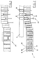
- Figure 1 is a plan view of the drawer conveyor during the adjustment phase;
- Figure 2 is a plan view of the drawer conveyor during operation;
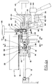
- Figure 3 is a plan view of an adjustment station;
- Figure 4a is a section view along the IV-IV line of the Figure 3 with the conveyor in operation;
- Figure 4b is a section view along the IV-IV line of the Figure while the conveyor is in the adjustment phase;
- Figure 5 is a section view along the V-V line of Figure 4a;
- Figure 6 is a section view along the VI-VI line of the Figure 4a;
- Figure 7 is a schematic plan view of the adjustment station in the operative phase;
- Figures 8a and 8b are two constructive particulars of the guides of the drawer body in the views frontal and back to the conveying direction.
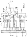
- With reference to Figure 2,
numeral 1 indicates a drawer conveyor, eachdrawer 2 of which consists of a firststationary element 18 and asecond element 21. - The
elements housing 5 designed to receive theproduct 6 loaded by known loading means, not illustrated. - The
products 6, hold in that manner, are conveyed along the packaging line up to the station S2 in which thedrawers 2 of saidconveyor 1 come up by the side of another conveyor 7. - Generally, the conveyor 7 has holding elements for placing thereon preformed
erected cases 8, and for conveying them along the packaging line with at least one open side facing theconveyor 1. - At a station S2, the
products 6 while being advanced are also translated inside thecases 8 by generic pushing means indicated with 9, to obtainpackages 10. - With reference to the figures 3, 4a and 5, the
drawer conveyor 1 includes a pair ofchains 11 parallel to the packaging line and carryingcross bars 12 that engage and support slidingly aconvey block 13 so as to advance it along the packaging line. - At its lower end, the
convey block 13, carries a pivoted idlecam following roller 14 designed to engage with acam 15. - The
cam 15 locates theconvey block 13 by moving it transversally, and at the station S2 the cam brings the convey block to come alongside the packages conveyor 7 so that thedrawers 2 are partially inserted into therespective cases 8, through the open side of the latters. - Near to its top, said convey
block 13, carries adrawer support body 17 that comprises the first "L"-like element 18, bound to said conveyblock 13, and the second "L"-like element 21, slidingly guided in direction normal to thefirst element 18. - The
first element 18 includes abottom wall 19 of thedrawer body 17, that is fixed to theconvey block 13, and a firststationary wall 20. - The
second element 21 includes asecond wall 22 and aplan 23 that is slidingly resting on the upper surface of thebottom wall 19 of thedrawer body 17. - With reference to Figures 8a and 8b, showing the guide means which connect the
elements 18 to theelement 21, theplan element 23, joint to thesecond wall 22, has its bottom fixed to asliding guide element 25, shaped like an upturned "T". Theelement 25 slides freely in aslot 24 made in the bottom wall 19 (see Fig. 3). - The
element 25 is a rack element that adheres and slides very near to the lower plane of thebottom wall 19, and extends transversally to thewalls - The
plane 23 and therack sliding element 25 are fixed one to another and they carry apivot 27 that pass through aslot 65 made at the end of anangular lever 28 pivoted in 29 on thebottom wall 19 of thedrawer body 17. - The other end of the
lever 28 carries aroller 32 that, when it is shifted, causes thesecond wall 22 to move while remaining parallel to thestationary wall 20 of thedrawer body 17. - In this way, translation means for the second wall are defined.
- With reference to Figures 4a and 4b, the
convey block 13 carries locking means which include arocker lever 34 pivoted in 33, the upper end of which carries atoothed sector 35 designed to be positioned in engagement with or disengagement from the teeth of therack 25. - When the
toothed sector 35 is pushed on therack 25, thesecond wall 22 is locked to thedrawer body 17 and to the conveyblock 13. - The lower part of the
lever 34 carries areset spring 36 and apivot 37 carrying aroller 38. - When the roller is shifted, in the way that is better explained in the following, the
toothed sector 35 is disengaged from therack 25, and thewall 22 is released from thedrawer body 17 and to theconvey block 13. - Still with reference to the figures 3, 4a, 4b and 6, the
conveyor structure 39 has fixed thereto asupport block 42 that in its upper part carries ashifting plate 43. - The
plate 43 slides transversally to the conveying direction by means of prismatic coupling guides (See in particular Fig. 6) and positioning means. - In fact, its end opposite to the
conveyor 1, thepositioning plate 43, is in screwed engagement with a threadedbar 44 that is keyed on ahandwheel 45 rotatably mounted rotatably on theconveyor structure 39. - In that manner, a coupling is obtained in which, by the rotations of the
handwheel 45, theplate 43 moves transversally to the conveying direction. - In its upper part, the
plate 43, carries aplate 40 pivoted by apivot 41. - The surface of the
plate 40 facing theconveyor 1 has made therein a funnel-like groove 46 which forms shifting means, or cam tracks 47, 48, designed to engage theroller 32 of theangle lever 28. - Linking means between the positioning means and the shifting means are now described.
- Inside the
support block 42, there is made anotch 49, in which thehead 50 of abolt 51 is inserted slidingly so that it cannot rotate. - The
bolt shaft 52 extends upwards passing through thewalls 53 of a cylindrical hole made in theplate 43, until it screws into theshaft 54 of a clamping 55 handwheel. - The free end of the
shaft 54 of said clamping hand-wheel 55 is in form of acone 56 and engages reciprocally with aconical hole 57 made in theplate 40 in such a way that, acting on thehandwheel 55, it is possible to obtain a coupling, between theplates - Thanks to the pivot between the
plates pivot 41, and to the conical coupling of thecone 56 with theconical hole 57, saidplate 40 can oscillate, as indicated in Fig. 4b, adapting conical coupling with clearance or a non-oscillating coupling, as indicated in Fig. 4a, adopting a conical clamped coupling. - In its lower part, the
support block 42 carries a slidingprismatic bar 58, placed transversally to the conveying direction. - The free end of said
bar 58, placed at the side of the conveyor, carries aplate 59 with acam profile 60 designed to cooperate with theroller 38 of the locking means. - The other end of said
bar 58 carries apivot 61, on which aroller 62 is rotatably mounted, saidroller 62 being engaged in apath 64 of adrum cam 63, mounted on ashaft 165 rotatably supported by thesame support block 42 and keyed on alever hub 66 for its rotation. - Acting on the
lever 66, theplate 59 proceeds or withdraws transversally to the conveying direction, entering in striking trajectory with theroller 38 or leaving the striking trajectory. - In the above described drawer conveyor, the automatic adjustment requires an adjustment station S1 placed along a section of the conveyor path and that can be enabled or disabled.
- An way of carrying out the adjustment operation is now described as a mere example, not limitative.
- When the drawer conveyor is standstill or in movement, the
plate 59 is moved forward, in thedrawer conveyor 1 direction, by turning theshaft 165 by means of thelever 66, in such a manner that the cam-shapedprofile 60 of theplate 58 be located along a path directed to strike therollers 38 of the locking means associated to the related support blocks 13, thus defining three operating sections for the said rollers 38 (see Figure 7). - With this configuration the
conveyor 1 goes on through one complete turn, so that all drawers pass through the citedstation 1 and undergoes therein the following actions: - the
roller 38 strikes the first raising section of thecam profile 60, so that therocker 34 swings from a first position, that causes thewall 22 to be locked to thestationary wall 20, to a second position wherein thewall 22 is released and free to move with respect to thestationary wall 20; - the second section of the
cam profile 60 keeps on acting on theroller 38, so that thewall 22 remains in a released condition, while theroller 32 engages the funnel-like groove 46 so that thewall 22 is set at a pre-determined distance from thestationary wall 20 by means of thelever translating means 28; - lastly, the third section of the
cam profile 60 progressively releases therocker 34 that, because of the action of thespring 36, swings back to the originary position, wherein thewall 22 results to be locked, and is thus well adjusted for the new article size. - When the turn of the conveyor has been completed all the drawers have passed through the adjustment station S1 and consequently all of them have been adjusted to suit the new article size.
- At this point, by acting on the
tightening wheel 55 the conical coupling 56-57 is disconnected, due to the clearance that results in the coupling, while by acting on thelever arm 66, theplate 59 is moved back, until it reaches its idle position (see Figure 4b). - During operation of the conveyor, the
rollers 38 do not strike thecam profile 60, since this last profile is in a retracted position. Theplate 40 is free to swing about thepivot 41 and along an arch that is defined by the clearance set in the conical coupling 56-57, so that possible oscillations of therollers 32 running in thegrooves 46 and which are not perfectly lined up, have no effects. - Furthermore, in order to avoid accidents, there is a
sensor 67 located near to thelever arm 66, designed to detect the operating or idle condition of theplate 59. - The most characterising feature of the present invention is that the
wall 22 is made movable with respect to thestationary wall 22, that thewall 22 is kept in such mobile condition for a pre-set section of theconveyor 1 path, so as to allow the distance between themovable wall 22 and the stationary wall to be adjusted to suit a certain size of the articles, and finally to lock again thewall 22 with respect to the conveyblock 13. - As an alternative to the above, the adjustment can be carried out by means of spacing plugs which are manually set into operation by an operator. The spacing plugs can be also somehow associated to the
conveyor 1, for example by mounting them on a disc, or a drum, that is coaxially keyed to one of the wheel on which the chains of theconveyor 1 run. - These spacing plugs should be placed between the
walls stationary wall 20, it is stopped by the plug, so that a predetermined distance between the twowalls movable wall 22. - Advantageously, the movable wall is moved against the elastic reaction of spring means, which allow to eliminate the effects of unavoidable clearances that exists among the means designed to move the movable wall. Thus dangerous mechanical stresses acting on the same moving means, due to anomalous situations which can occur while adjusting the size of the drawer, are avoided.
- As an alternative to the
rack member 25 and to the connectedtoothed sector 35, any other mechanical means able to allow blocking of themovable member 25 to the conveyblock 13, can be used. For example a high friction material can replace the toothing on the rack member and the toothed sector. - It must be stressed that what has been said above concerns every drawer so that a possible anomalous situation affecting the means designed to drive the drawer conveyor and/or the means designed to carry out the adjustment, do not have similar effects on all the drawers.
- It must be also highlighted that all what has been proposed can be applied to a drawer conveyor including a pair of chains, with all the advantages that this brings about with respect to the prior art described in the introductory statement.
Claims (12)
- Method for automatically adjusting a drawer conveyor in accordance with the size of the article (6) to be transported, said conveyor (1) running along a closed loop path and being equipped with conveying drawers (2), each comprising a pair of walls (20,22);
the said method being characterised in that it includes the following phases:- releasing a wall (22) of a drawer (2) while this drawer (2) is running along a first section of the said loop path:- shifting this wall (22) while the drawer is running along a second section of the said path, until the movable wall is positioned at a pre-set distance from the stationary wall (20);- locking again the wall (22) previously released, when the drawer (2) is running a third section of the same path. - Method according to claim 1, characterised in that an adjusting operating station (S1) is activated to carry out the said phases, and operates for a time necessary to all the drawers (2) to pass through the same station (S1).
- Conveyor automatically adjusted in accordance with the size of the articles to be transported, the said conveyor (1) running along a closed loop path and being equipped with transporting drawers (2), each comprising a pair of walls (20,22), said conveyor including:conveying means comprising a first stationary wall (20) and a second wall (22), this second wall (22) being adapted to take either the one or the other of two different configurations, namely a first configuration in which the second wall (22) is locked, and a second configuration in which this second wall (22) is released and movable with respect to the said first stationary wall (20);operating means designed to release the said second wall (22) of a drawer (2) while this drawer (2) is running a first section of the said closed loop path, to keep the same wall (22) free while the drawer (2) is running a second section of the closed loop path, and then to lock the wall (22) previously released when the said drawer has reached a third section of the same path;positioning means for locating the said second wall (22) at a pre-set distance from the said first stationary wall (20) while said second wall is kept free.
- Conveyor according to claim 3, characterised in that the said transporting means further include:guiding means designed to slidingly guide said second wall (22) while moving nearer, to or farther, from said first stationary wall (20);locking means aimed at blocking the said second wall (22) with respect to the first stationary wall (20); andtranslating means designed to impose a translation to said second wall (22).
- Conveyor according to claim 4, characterised in that said guiding means include a pair of prismatic couplings positioned in a central position with respect of a drawer (2) and along a longitudinal direction of the same drawer, and including a sliding member (25) positioned beneath the bottom of the drawer (2), inside a groove made in the transporting means, said sliding member (25) having an end fixed to said second wall (22), thus defining a double "T" sliding along a slot (24) made in the bottom (19) of said drawer, transversally with respect of said walls.
- Conveyor according to claim 4, characterised in that said locking means include:a rack member (25) fixed to said second wall (22) and slidingly guided by the transporting means;a rocker member (34) that is pivoted to said transporting means and swings perpendicularly to said rack member, said rocker member having a toothed sector (35) fastened to an end thereof, this toothed sector being adapted to engage and disengage said rack member, while the other end of the said rocker member (34) has a cam-follower roller (38) designed to cooperate with said operating means for causing said second rocker member to swing;a re-setting spring (36) acting on said rocker member (34), said spring being designed to re-set said rocker member (34) to the position where it is in engagement with said rack member (25).
- Conveyor according to claim 4, characterised in that said translating means include an angle lever (28) positioned beneath the bottom of the drawer (2) and pivoted thereto, said angle lever (28) having an end hinged to said second wall (22) while the other end of said angle lever has a cam-follower roller (32) designed to cooperate with the said positioning means.
- Conveyor according to claim 3, characterised in that said operating means include:first shifting means, designed to cooperate with said transporting means, and which include a plate (59) movable along a direction that is transverse to the conveyor direction, with an edge of said plate facing said transporting means profiled to form a cam (60) and extending longitudinally to the transporting direction, so that said edge cooperates with said transporting means, said plate (59) also bearing a cam-follower roller (62) positioned near an edge of said plate opposite to the cam-profiled edge, this roller being designed to run inside a cam groove (64) made on a drum (63) rotatably supported by the conveyor structure and aimed at causing the sliding of said plate (59) transversally with respect to the transporting direction;second shifting means disposed in accordance with a longitudinal direction and movable along a direction transverse to said transporting direction;adjusting means designed to move said shifting means and to define a transverse position for the same shifting means;link means designed to connect said shifting means to said adjusting means with or without possibility of oscillation.
- Conveyor according to claim 8, characterised in the fact that said shifting means include a first shifting plate (43) with a funnel-like groove (46) parallel to the transporting direction and designed to engage a roller (32) of translating means of said second wall (22) supported by said transporting means.
- Conveyor according to claim 8, characterised in that said adjusting means include an adjusting wheel (45) rotatably mounted on the conveyor structure and supporting a threaded bar (44) keyed thereto and perpendicular to the transporting means, this threaded bar being in screw engagement with a second positioning plate (40).
- Conveyor according to claim 8, characterised in that said link means include a conical adjustable coupling comprising a conical member connected to said shifting means and another conical member connected to said adjusting means.
- Conveyor according to claim 3, characterised in that it includes sensor means cooperating with said operating means to detect the operation or non-operation state for these last operating means.
Applications Claiming Priority (2)
| Application Number | Priority Date | Filing Date | Title |
|---|---|---|---|
| IT93BO000058A IT1266263B1 (en) | 1993-02-22 | 1993-02-22 | METHOD AND CONVEYOR FOR AUTOMATIC SIZE CHANGE IN SINGLE CLOSED LOOP DRAWER CONVEYORS |
| ITBO930058 | 1993-02-22 |
Publications (3)
| Publication Number | Publication Date |
|---|---|
| EP0612662A2 EP0612662A2 (en) | 1994-08-31 |
| EP0612662A3 EP0612662A3 (en) | 1994-10-19 |
| EP0612662B1 true EP0612662B1 (en) | 1997-01-15 |
Family
ID=11338724
Family Applications (1)
| Application Number | Title | Priority Date | Filing Date |
|---|---|---|---|
| EP94830067A Expired - Lifetime EP0612662B1 (en) | 1993-02-22 | 1994-02-18 | Method for automatically adjusting a drawer conveyor in accordance with the size of articles to be transported, and conveyor that carries out the method |
Country Status (9)
| Country | Link |
|---|---|
| US (1) | US5392896A (en) |
| EP (1) | EP0612662B1 (en) |
| JP (1) | JP3860229B2 (en) |
| AT (1) | ATE147695T1 (en) |
| CA (1) | CA2116086C (en) |
| DE (1) | DE69401444T2 (en) |
| DK (1) | DK0612662T3 (en) |
| ES (1) | ES2097627T3 (en) |
| IT (1) | IT1266263B1 (en) |
Families Citing this family (17)
| Publication number | Priority date | Publication date | Assignee | Title |
|---|---|---|---|---|
| US5904026A (en) * | 1997-12-12 | 1999-05-18 | Riverwood International Corporation | Adjustable height flight |
| US6374997B1 (en) | 2000-03-24 | 2002-04-23 | Langen Packaging Inc. | Conveyor system |
| JP4699586B2 (en) * | 2000-05-10 | 2011-06-15 | 株式会社岡村製作所 | Loading equipment for rotary racks |
| DE10041241B4 (en) * | 2000-08-22 | 2008-02-07 | Grecon Dimter Holzoptimierung Nord Gmbh & Co. Kg | Aligning and feeding device for plate-like workpieces |
| US7278531B2 (en) * | 2004-06-29 | 2007-10-09 | Hartness International, Inc. | Flexible conveyor and connection elements |
| US7021453B2 (en) * | 2003-11-13 | 2006-04-04 | Hartness International, Inc. | Conveyor with gear mechanism gripper and related conveyor link |
| US7036658B2 (en) | 2003-11-13 | 2006-05-02 | Hartness International, Inc. | Gripper conveyor with clear conveying path and related conveyor link |
| US7264113B2 (en) | 2003-11-13 | 2007-09-04 | Hartness International, Inc. | Pivotable conveyor and link |
| US7207434B2 (en) | 2003-11-13 | 2007-04-24 | Hartness International, Inc. | Conveyor with center-actuatable gripper, and related conveyor link |
| US7055677B2 (en) * | 2003-11-13 | 2006-06-06 | Hartness International, Inc. | Conveyor with movable grippers, and related conveyor link |
| US7261199B2 (en) * | 2004-06-29 | 2007-08-28 | Hartness International, Inc. | Neck gripping conveyor and link, and related rotary filler and system |
| US7216758B2 (en) | 2003-11-13 | 2007-05-15 | Hartness International, Inc. | Conveyor with opposed spring-loaded grippers, and related conveyor link |
| US7055676B2 (en) * | 2003-11-13 | 2006-06-06 | Hartness International, Inc. | Conveyor with movable gripper and related conveyor link |
| US7299832B2 (en) * | 2004-06-29 | 2007-11-27 | Hartness International, Inc. | Rotary filling machine and related components, and related method |
| US7331156B2 (en) * | 2004-06-29 | 2008-02-19 | Hartness International, Inc. | System for securely conveying articles and related components |
| US7185753B2 (en) * | 2004-09-28 | 2007-03-06 | Hartness International, Inc. | Shuttle conveyor |
| ITBO20050058A1 (en) * | 2005-02-07 | 2006-08-08 | Oam Spa | LINE FOR THE CONVEYANCE OF ITEMS |
Family Cites Families (4)
| Publication number | Priority date | Publication date | Assignee | Title |
|---|---|---|---|---|
| US3809210A (en) * | 1972-03-03 | 1974-05-07 | Scandia Packaging Mach | Method and apparatus for conveying a container |
| IT1208293B (en) * | 1987-05-08 | 1989-06-12 | Zanasi Nuova Spa | FOR ADAPTATION TO CARTONS AND AUTOMATIC CARTONING MACHINES OF TYPES OF DIFFERENT RECTILINEAR FORMAT AND WITH CONTINUOUS OPERATION EQUIPPED WITH ADJUSTMENTS |
| IT1247418B (en) * | 1991-02-07 | 1994-12-13 | Oam Spa | IMPROVED DEVICE, FOR THE RECEPTION AND SYNCHRONIZED TRANSFER OF VARIOUS ITEMS. |
| IT1248234B (en) * | 1991-06-14 | 1995-01-05 | Gd Spa | DEVICE FOR RECEPTION AND TRANSFER OF PRODUCTS OR STACKS OF PRODUCTS SUBSTANTIALLY PARALLELEPIPEDI TO A SUBSEQUENT CONVEYOR. |
-
1993
- 1993-02-22 IT IT93BO000058A patent/IT1266263B1/en active IP Right Grant
-
1994
- 1994-02-18 EP EP94830067A patent/EP0612662B1/en not_active Expired - Lifetime
- 1994-02-18 US US08/198,483 patent/US5392896A/en not_active Expired - Lifetime
- 1994-02-18 ES ES94830067T patent/ES2097627T3/en not_active Expired - Lifetime
- 1994-02-18 DE DE69401444T patent/DE69401444T2/en not_active Expired - Lifetime
- 1994-02-18 DK DK94830067.8T patent/DK0612662T3/da active
- 1994-02-18 AT AT94830067T patent/ATE147695T1/en not_active IP Right Cessation
- 1994-02-21 CA CA002116086A patent/CA2116086C/en not_active Expired - Lifetime
- 1994-02-22 JP JP02421494A patent/JP3860229B2/en not_active Expired - Fee Related
Also Published As
| Publication number | Publication date |
|---|---|
| CA2116086A1 (en) | 1994-08-23 |
| JPH0789612A (en) | 1995-04-04 |
| DE69401444T2 (en) | 1997-04-30 |
| ES2097627T3 (en) | 1997-04-01 |
| CA2116086C (en) | 2004-06-22 |
| EP0612662A3 (en) | 1994-10-19 |
| ITBO930058A1 (en) | 1994-08-22 |
| DK0612662T3 (en) | 1997-02-24 |
| ITBO930058A0 (en) | 1993-02-22 |
| JP3860229B2 (en) | 2006-12-20 |
| DE69401444D1 (en) | 1997-02-27 |
| US5392896A (en) | 1995-02-28 |
| EP0612662A2 (en) | 1994-08-31 |
| IT1266263B1 (en) | 1996-12-27 |
| ATE147695T1 (en) | 1997-02-15 |
Similar Documents
| Publication | Publication Date | Title |
|---|---|---|
| EP0612662B1 (en) | Method for automatically adjusting a drawer conveyor in accordance with the size of articles to be transported, and conveyor that carries out the method | |
| CA1290774C (en) | Selective product feed apparatus | |
| FI57574B (en) | TRANSPORT FOER I EN FJAELLSTROEM KOMMANDE TRYCKPRODUKTER MED VID ETT KRINGLOEPANDE DRAGORGAN PAO AVSTAOND FAESTA GRIPARE | |
| US4517788A (en) | Mechanism for filling bags of different sizes | |
| KR100563396B1 (en) | Device for receiving and transporting objects | |
| EP0403190A2 (en) | In-line package strapping system | |
| US6374997B1 (en) | Conveyor system | |
| US4285185A (en) | Article carrier feeding and control apparatus | |
| JPH07144736A (en) | Endless encircling type loose article transfer device including separate transfer means | |
| CN108203010B (en) | Gripper lock device and sheet processing apparatus | |
| EP1136359B1 (en) | Machine for packaging mattresses in a sheet unwound continuously from a roll | |
| US4262468A (en) | Device for spacing apart objects conveyed through an operation-performing machine | |
| US6354060B1 (en) | Packaging machine | |
| US2706031A (en) | Package conveying and orienting apparatus | |
| NL8303807A (en) | TRANSPORT DEVICE. | |
| US3968623A (en) | Wrap-around carton forming machine | |
| CN108778933B (en) | Device for moving an article advancing continuously along an advancing direction | |
| US3786910A (en) | Vertical conveyor | |
| US4015403A (en) | Wrap-around carton forming machine | |
| EP0561756B1 (en) | Gripper conveyor | |
| US4028866A (en) | Wrap-around carton forming machine | |
| EP1003675B1 (en) | Transfer mechanism | |
| NL8204097A (en) | METHOD AND MEANS FOR STRAPING BUCKLES ON BELTS | |
| US3999683A (en) | Wrap-around carton forming machine | |
| EP1846311A1 (en) | A device for conveying items |
Legal Events
| Date | Code | Title | Description |
|---|---|---|---|
| PUAI | Public reference made under article 153(3) epc to a published international application that has entered the european phase |
Free format text: ORIGINAL CODE: 0009012 |
|
| PUAL | Search report despatched |
Free format text: ORIGINAL CODE: 0009013 |
|
| AK | Designated contracting states |
Kind code of ref document: A2 Designated state(s): AT BE CH DE DK ES FR GB GR IE IT LI MC NL PT SE |
|
| AK | Designated contracting states |
Kind code of ref document: A3 Designated state(s): AT BE CH DE DK ES FR GB GR IE IT LI MC NL PT SE |
|
| 17P | Request for examination filed |
Effective date: 19950228 |
|
| GRAG | Despatch of communication of intention to grant |
Free format text: ORIGINAL CODE: EPIDOS AGRA |
|
| GRAH | Despatch of communication of intention to grant a patent |
Free format text: ORIGINAL CODE: EPIDOS IGRA |
|
| 17Q | First examination report despatched |
Effective date: 19960525 |
|
| GRAG | Despatch of communication of intention to grant |
Free format text: ORIGINAL CODE: EPIDOS AGRA |
|
| GRAH | Despatch of communication of intention to grant a patent |
Free format text: ORIGINAL CODE: EPIDOS IGRA |
|
| GRAA | (expected) grant |
Free format text: ORIGINAL CODE: 0009210 |
|
| ITF | It: translation for a ep patent filed |
Owner name: INVENTION S.N.C. |
|
| AK | Designated contracting states |
Kind code of ref document: B1 Designated state(s): AT BE CH DE DK ES FR GB GR IE IT LI MC NL PT SE |
|
| PG25 | Lapsed in a contracting state [announced via postgrant information from national office to epo] |
Ref country code: GR Free format text: LAPSE BECAUSE OF FAILURE TO SUBMIT A TRANSLATION OF THE DESCRIPTION OR TO PAY THE FEE WITHIN THE PRESCRIBED TIME-LIMIT Effective date: 19970115 |
|
| REF | Corresponds to: |
Ref document number: 147695 Country of ref document: AT Date of ref document: 19970215 Kind code of ref document: T |
|
| REG | Reference to a national code |
Ref country code: CH Ref legal event code: EP |
|
| REG | Reference to a national code |
Ref country code: CH Ref legal event code: NV Representative=s name: R. A. EGLI & CO. PATENTANWAELTE |
|
| REG | Reference to a national code |
Ref country code: DK Ref legal event code: T3 |
|
| REF | Corresponds to: |
Ref document number: 69401444 Country of ref document: DE Date of ref document: 19970227 |
|
| ET | Fr: translation filed | ||
| REG | Reference to a national code |
Ref country code: IE Ref legal event code: FG4D Free format text: 71579 |
|
| REG | Reference to a national code |
Ref country code: ES Ref legal event code: FG2A Ref document number: 2097627 Country of ref document: ES Kind code of ref document: T3 |
|
| PG25 | Lapsed in a contracting state [announced via postgrant information from national office to epo] |
Ref country code: PT Effective date: 19970415 |
|
| PLBE | No opposition filed within time limit |
Free format text: ORIGINAL CODE: 0009261 |
|
| STAA | Information on the status of an ep patent application or granted ep patent |
Free format text: STATUS: NO OPPOSITION FILED WITHIN TIME LIMIT |
|
| 26N | No opposition filed | ||
| REG | Reference to a national code |
Ref country code: GB Ref legal event code: IF02 |
|
| PGFP | Annual fee paid to national office [announced via postgrant information from national office to epo] |
Ref country code: MC Payment date: 20020123 Year of fee payment: 9 Ref country code: IE Payment date: 20020123 Year of fee payment: 9 |
|
| PGFP | Annual fee paid to national office [announced via postgrant information from national office to epo] |
Ref country code: AT Payment date: 20020220 Year of fee payment: 9 |
|
| PG25 | Lapsed in a contracting state [announced via postgrant information from national office to epo] |
Ref country code: IE Free format text: LAPSE BECAUSE OF NON-PAYMENT OF DUE FEES Effective date: 20030218 Ref country code: AT Free format text: LAPSE BECAUSE OF NON-PAYMENT OF DUE FEES Effective date: 20030218 |
|
| PG25 | Lapsed in a contracting state [announced via postgrant information from national office to epo] |
Ref country code: MC Free format text: LAPSE BECAUSE OF NON-PAYMENT OF DUE FEES Effective date: 20030228 |
|
| REG | Reference to a national code |
Ref country code: IE Ref legal event code: MM4A |
|
| PGFP | Annual fee paid to national office [announced via postgrant information from national office to epo] |
Ref country code: NL Payment date: 20060221 Year of fee payment: 13 |
|
| PGFP | Annual fee paid to national office [announced via postgrant information from national office to epo] |
Ref country code: DK Payment date: 20060222 Year of fee payment: 13 |
|
| PGFP | Annual fee paid to national office [announced via postgrant information from national office to epo] |
Ref country code: BE Payment date: 20060227 Year of fee payment: 13 |
|
| PGFP | Annual fee paid to national office [announced via postgrant information from national office to epo] |
Ref country code: SE Payment date: 20070215 Year of fee payment: 14 |
|
| REG | Reference to a national code |
Ref country code: DK Ref legal event code: EBP |
|
| NLV4 | Nl: lapsed or anulled due to non-payment of the annual fee |
Effective date: 20070901 |
|
| BERE | Be: lapsed |
Owner name: *A.M.R.P. HANDELS A.G. Effective date: 20070228 |
|
| PG25 | Lapsed in a contracting state [announced via postgrant information from national office to epo] |
Ref country code: BE Free format text: LAPSE BECAUSE OF NON-PAYMENT OF DUE FEES Effective date: 20070228 |
|
| PG25 | Lapsed in a contracting state [announced via postgrant information from national office to epo] |
Ref country code: NL Free format text: LAPSE BECAUSE OF NON-PAYMENT OF DUE FEES Effective date: 20070901 Ref country code: DK Free format text: LAPSE BECAUSE OF NON-PAYMENT OF DUE FEES Effective date: 20070228 |
|
| EUG | Se: european patent has lapsed | ||
| PG25 | Lapsed in a contracting state [announced via postgrant information from national office to epo] |
Ref country code: SE Free format text: LAPSE BECAUSE OF NON-PAYMENT OF DUE FEES Effective date: 20080219 |
|
| REG | Reference to a national code |
Ref country code: DE Ref legal event code: R082 Ref document number: 69401444 Country of ref document: DE Representative=s name: HAUCK PATENT- UND RECHTSANWAELTE, DE |
|
| PGFP | Annual fee paid to national office [announced via postgrant information from national office to epo] |
Ref country code: IT Payment date: 20120224 Year of fee payment: 19 |
|
| PGFP | Annual fee paid to national office [announced via postgrant information from national office to epo] |
Ref country code: ES Payment date: 20130220 Year of fee payment: 20 Ref country code: GB Payment date: 20130220 Year of fee payment: 20 Ref country code: DE Payment date: 20130220 Year of fee payment: 20 Ref country code: CH Payment date: 20130220 Year of fee payment: 20 |
|
| PGFP | Annual fee paid to national office [announced via postgrant information from national office to epo] |
Ref country code: FR Payment date: 20130425 Year of fee payment: 20 |
|
| REG | Reference to a national code |
Ref country code: DE Ref legal event code: R071 Ref document number: 69401444 Country of ref document: DE |
|
| REG | Reference to a national code |
Ref country code: CH Ref legal event code: PL |
|
| REG | Reference to a national code |
Ref country code: GB Ref legal event code: PE20 Expiry date: 20140217 |
|
| PG25 | Lapsed in a contracting state [announced via postgrant information from national office to epo] |
Ref country code: DE Free format text: LAPSE BECAUSE OF EXPIRATION OF PROTECTION Effective date: 20140219 Ref country code: GB Free format text: LAPSE BECAUSE OF EXPIRATION OF PROTECTION Effective date: 20140217 |
|
| REG | Reference to a national code |
Ref country code: ES Ref legal event code: FD2A Effective date: 20140925 |
|
| PG25 | Lapsed in a contracting state [announced via postgrant information from national office to epo] |
Ref country code: ES Free format text: LAPSE BECAUSE OF EXPIRATION OF PROTECTION Effective date: 20140219 |