EP0612572B1 - Method of making a mandrel comprising a drill section - Google Patents
Method of making a mandrel comprising a drill section Download PDFInfo
- Publication number
- EP0612572B1 EP0612572B1 EP93301341A EP93301341A EP0612572B1 EP 0612572 B1 EP0612572 B1 EP 0612572B1 EP 93301341 A EP93301341 A EP 93301341A EP 93301341 A EP93301341 A EP 93301341A EP 0612572 B1 EP0612572 B1 EP 0612572B1
- Authority
- EP
- European Patent Office
- Prior art keywords
- mandrel
- drill section
- blank
- stem
- diameter
- Prior art date
- Legal status (The legal status is an assumption and is not a legal conclusion. Google has not performed a legal analysis and makes no representation as to the accuracy of the status listed.)
- Expired - Lifetime
Links
Images



Classifications
-
- F—MECHANICAL ENGINEERING; LIGHTING; HEATING; WEAPONS; BLASTING
- F16—ENGINEERING ELEMENTS AND UNITS; GENERAL MEASURES FOR PRODUCING AND MAINTAINING EFFECTIVE FUNCTIONING OF MACHINES OR INSTALLATIONS; THERMAL INSULATION IN GENERAL
- F16B—DEVICES FOR FASTENING OR SECURING CONSTRUCTIONAL ELEMENTS OR MACHINE PARTS TOGETHER, e.g. NAILS, BOLTS, CIRCLIPS, CLAMPS, CLIPS OR WEDGES; JOINTS OR JOINTING
- F16B19/00—Bolts without screw-thread; Pins, including deformable elements; Rivets
- F16B19/04—Rivets; Spigots or the like fastened by riveting
- F16B19/08—Hollow rivets; Multi-part rivets
- F16B19/083—Self-drilling rivets
-
- B—PERFORMING OPERATIONS; TRANSPORTING
- B21—MECHANICAL METAL-WORKING WITHOUT ESSENTIALLY REMOVING MATERIAL; PUNCHING METAL
- B21J—FORGING; HAMMERING; PRESSING METAL; RIVETING; FORGE FURNACES
- B21J15/00—Riveting
- B21J15/10—Riveting machines
- B21J15/36—Rivet sets, i.e. tools for forming heads; Mandrels for expanding parts of hollow rivets
-
- B—PERFORMING OPERATIONS; TRANSPORTING
- B21—MECHANICAL METAL-WORKING WITHOUT ESSENTIALLY REMOVING MATERIAL; PUNCHING METAL
- B21K—MAKING FORGED OR PRESSED METAL PRODUCTS, e.g. HORSE-SHOES, RIVETS, BOLTS OR WHEELS
- B21K1/00—Making machine elements
- B21K1/58—Making machine elements rivets
- B21K1/60—Making machine elements rivets hollow or semi-hollow rivets
-
- B—PERFORMING OPERATIONS; TRANSPORTING
- B21—MECHANICAL METAL-WORKING WITHOUT ESSENTIALLY REMOVING MATERIAL; PUNCHING METAL
- B21K—MAKING FORGED OR PRESSED METAL PRODUCTS, e.g. HORSE-SHOES, RIVETS, BOLTS OR WHEELS
- B21K5/00—Making tools or tool parts, e.g. pliers
- B21K5/02—Making tools or tool parts, e.g. pliers drilling-tools or other for making or working on holes
Definitions
- the prior art "self-drilling blind rivet” comprises a tubular rivet body and an elongate mandrel inserted through the rivet body.
- the mandrel has at its one end a drill section capable of self-drilling an object in which the blind rivet is to be attached.
- the drill section has an outer diameter comparatively greater than that of the tubular rivet body.
- GB-A-1 392 601 describes a method of forming an elongate mandrel having an end integral with a drill section by cold forging a short stem integral with the end of the mandrel and having a diameter greater than the diameter of the mandrel, to form the drill section, and trimming the drill section to remove therefrom the scrap resulting from the cold forging.
- a method of making an elongate mandrel having an end integral with a drill section does comprise the steps of: subjecting a single columnar piece of material to a heading process so as to make a blank composed of the elongate mandrel having a diameter "d", a short stem integral with the end of the mandrel and having a diameter "D" greater than the diameter "d” of the mandrel, and a flange integral with the short stem and extending from one end thereof opposite to the mandrel; then cold forging the stem to produce the drill section having end edges disposed to face the flange; and subsequently trimming the drill section so as to remove therefrom the flange together with scrap possibly resulting from the cold forging of the short stem.
- the present invention provides a highly efficient method for the mass production of a mandrel comprising a drill section and adapted to construct a self-drilling blind rivet, wherein the drill section is not a separate tip jointed to the mandrel but is formed in one piece together with the mandrel from a single piece of raw material.
- the blank mentioned above may be a piece of hardenable steel so that only its drill section is hardened in a high-frequency heating apparatus.
- the blank may be made of a low carbon steel and subsequently carburized before only the drill section is selectively hardened in the high-frequency heating apparatus.
- the method proposed herein will enable not only the mass production of the blank by using any conventional type of the headers, but also the efficient forming of the drill section by a conventional cold forging technique.
- FIG. 1(a) to 1(c) illustrate the step of producing a blank "N".
- a columnar piece “M” shown in FIG. 1(a) is a raw material used to prepare the blank "N", and is a length severed from a raw coil of a hardenable carbon steel.
- the diameter "D" of the columnar piece “M” is slightly smaller than that of a drill section which will be described below in detail.
- the heading process is carried out using at first a pressing punch 16 to force the columnar piece downwardly into a diameter-reducing die 15.
- a thin and elongate mandrel 1, which is formed in this way from a lower portion of the columnar piece "M”, will have a diameter "d” substantially equal to a half of the diameter "D” of said piece "M”.
- a short stem 2 for the drill section will also be formed thicker from an upper portion of the columnar piece.
- the stem 2 integral with the mandrel 1 is of a diameter substantially equal to the diameter "D" of the piece "M”, such that a reduced and curved zone 1a appears between the short stem and the mandrel, thus providing a transitional blank "M1".
- this transitional blank "M1” will be transferred into a finishing die 17 shown in Figure 1(c).
- another punch 18 forces the blank "M1" downwards so that the curved zone 1a disappears, and a flange 3 is formed integral with the short stem 2 at its end opposite to the mandrel.
- a lower end of the mandrel 1 is chamfered simultaneously by the die 17, thus providing a finished blank "N".
- the flange 3 disposed at an extremity of this blank will facilitate the automatic control of the following step of cold forging the drill section 4.
- the reference numeral 19 denotes a knocking-out pin.
- Figures 2(a) to 2(c) illustrate the step of cold forging the drill section 4 previously mentioned above.
- a pair of molds 21A and 21B of a pinch pointer as shown in Figures 3 and 4 will forcibly grip the short stem 2 so as to cold forge it.
- the contour of the drill section 4 is produced by the inner engraved surfaces of the molds, and swelling excessive material will bulge out of the molds to form scrap 10 along and around the outer periphery of the thus forged drill section.
- the configuration of the mating molds 21A and 21B are as follows. They are of the same shape and arranged symmetrical with each other as shown in FIGS. 3 and 4, and each mold has the inner surface composed of two ( or "first" and “second” ) flat zones 22 and 23 extending stepwise and in parallel with one another.
- a recess 24 for forming one of a number of lands 5 on the drill section 4 is engraved to extend or initiate from the first one of the flat zones 22.
- a protrusion 25 for forming a ( chip-discharging ) vertical groove 6 on the drill section extends or initiates from the other, i.e., "second", flat zone 23.
- a first sharp ridge 26a defining one of the end edges 7a of the drill section is disposed, together with a third sharp ridge 27a defining one of side the edges 8a, to terminate at the first flat zone 22.
- a second sharp ridge 26b defining the other end edges 7b of the drill section is disposed, together with a fourth sharp ridge 27b defining the other side edges 8b, to similarly terminate at the second flat zone 23.
- a top end of the first sharp ridge 26a is connected by a short straight line to a top end of the second sharp ridge 26b, in such a manner that the straight line provides a fifth ridge for forming a chisel edge on the drill section 4.
- the drill section 4 will be produced in the following manner using the pair of the molds 21A and 21B.
- the blank "N” will be supported at its flange 3 on a support ing end 31 of a feeder disc 30, and then transported into and positioned between the molds 21A and 21B.
- the flange 3 will be urged downwards by a retainer pin 32 in a direction indicated by the arrow in FIG. 3 by means of a spring not shown, while the molds 21A and 21B are strongly pressed towards each other to cold forge the stem 2 to give the drill section 4.
- This drill section 4 produced in this way will have the end edges 7a and 7b as well as the chisel edge 9, which edges are in such a position as to face the flange 3 as shown in Figure 2(b).
- the scrap 10 extends along, around and integral with the periphery of the drill section.
- any conventional trimming die not shown may be used to remove from the drill section the scrap 10 together with the flange.
- a drilling mandrel 11 composed of the elongate mandrel 1 integral with the thicker drill section 4 will be obtained as illustrated in Figure 2(c).
- annular recess 12 may be formed prior to the cold forging step at a boundary between a major portion and a minor portion of the short stem 2, so that only the former is forged, with the latter portion 2a being left unforged.
- Such an additional step is effective to prevent any possible flash 10a from remaining unremoved from the ends of side edges 8a and 8b of the drill section 4, as indicated by the phantom line in Figure 2(c), when the trimming of the scrap 10 is done. Even if any residual portion of the flash 10a would remain, it will be accommodated in the recess 12 so as not to impair the drilling performance.
- some radially extending protrusions 14 may be formed on a shoulder surface 13 between the stem 2 and the mandrel 1 in a manner shown in FIGS. 9(a) and 9(b), when the blank "N" is made.
- Those protrusions will play a certain important role when the blind rivet is used, which rivet will be composed of the mandrel 1 inserted through a tubular rivet body 40 ( shown in FIG. 7 ).
- Such protrusions will claw the end surface of the rivet body 40 so that a torque can be transmitted to the drill section 4 not only through the mandrel 1 but also from the rivet body through the protrusions 14, thus enabling the drill section to be driven with a sufficient force.
- FIG. 7 shows a self-drilling blind rivet which is assembled by fitting the tubular rivet body 40 on the finished mandrel 11 having the hardened drill section.
- the rivet body has a central bore 41 for receiving the mandrel 1 as well as a flange-like portion 42 integral with an end of said body 40.
- the rivet body 40 is made of a softer metal such as an aluminum alloy.
- the elongate mandrel having its one end formed integral with the drill section of a larger diameter can be manufactured from a single piece of a raw material, efficiently at a mass production scale and a reduced cost, by using any conventional heading machine and cold forging apparatus
Landscapes
- Engineering & Computer Science (AREA)
- Mechanical Engineering (AREA)
- General Engineering & Computer Science (AREA)
- Forging (AREA)
- Solid-Phase Diffusion Into Metallic Material Surfaces (AREA)
- Heat Treatment Of Articles (AREA)
Description
- The prior art "self-drilling blind rivet" comprises a tubular rivet body and an elongate mandrel inserted through the rivet body. The mandrel has at its one end a drill section capable of self-drilling an object in which the blind rivet is to be attached. The drill section has an outer diameter comparatively greater than that of the tubular rivet body. However, there has not been offered any effective method to form in a mass-production manner such a drill section at the end of said elongate mandrel. Consequently, a great demand for this type of blind rivet has not been met with a sufficient supply.
- The present inventor, who had made best efforts to supply such an unsatisfied demand, already proposed a method as disclosed in the Japanese Patent Laying-Open Gazette Hei. 2-197347 ( corresponding to the Unites States Patent No. 4,998,853 ). In this method, a short drill tip is adjoined or welded to one end of a mandrel.
- This previous method has however proved not necessarily satisfactory due to a certain difficulty in ensuring an coaxial relationship between each mandrel and each drill tip jointed thereto. Thus, the mass production of the blind rivet according to the previous method proposed by the present inventor has not been realized yet, because a specially designed automatic welder is needed therefor but has not been offered.
- GB-A-1 392 601 describes a method of forming an elongate mandrel having an end integral with a drill section by cold forging a short stem integral with the end of the mandrel and having a diameter greater than the diameter of the mandrel, to form the drill section, and trimming the drill section to remove therefrom the scrap resulting from the cold forging.
- According to the present invention there is provided a method of making an elongate mandrel having an end integral with a drill section does comprise the steps of: subjecting a single columnar piece of material to a heading process so as to make a blank composed of the elongate mandrel having a diameter "d", a short stem integral with the end of the mandrel and having a diameter "D" greater than the diameter "d" of the mandrel, and a flange integral with the short stem and extending from one end thereof opposite to the mandrel; then cold forging the stem to produce the drill section having end edges disposed to face the flange; and subsequently trimming the drill section so as to remove therefrom the flange together with scrap possibly resulting from the cold forging of the short stem.
- Thus the present invention provides a highly efficient method for the mass production of a mandrel comprising a drill section and adapted to construct a self-drilling blind rivet, wherein the drill section is not a separate tip jointed to the mandrel but is formed in one piece together with the mandrel from a single piece of raw material.
- The blank mentioned above may be a piece of hardenable steel so that only its drill section is hardened in a high-frequency heating apparatus. Alternatively, the blank may be made of a low carbon steel and subsequently carburized before only the drill section is selectively hardened in the high-frequency heating apparatus.
- The method proposed herein will enable not only the mass production of the blank by using any conventional type of the headers, but also the efficient forming of the drill section by a conventional cold forging technique.
- The invention will be described, by way of example only, with reference to the accompanying drawings, in which:
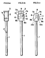
- Figures 1(a) to 1(c) show the step of making a blank in an embodiment of the method proposed herein;
- Figures 2(a) to 2(c) show the step of forming a drill section from the blank in the embodiment;
- Figure 3 is a front elevation of a pair of molds used for the cold forging of the drill section;
- Figure 4 is a plan view showing the molds disposed vis-a-vis;
- Figure 5 shows the step of forming a breakable annular groove on a mandrel as a portion of the blank;
- Figure 6 shows the step of heating and hardening the drill section;
- Figure 7 is a front elevation showing partly in cross section a self-drilling blind rivet which comprises the mandrel having the drill section;
- Figures 8(a) to 8(c) show the step of forming the drill section in a modified embodiment; and
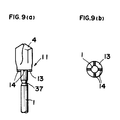
- Figures 9(a) and 9(b) are a front elevation and a bottom view, respectively, showing the mandrel with the drill section which are manufactured in a further modified embodiment.
- An embodiment of the present invention will now be described referring to the drawings.
- Figures 1(a) to 1(c) illustrate the step of producing a blank "N". A columnar piece "M" shown in FIG. 1(a) is a raw material used to prepare the blank "N", and is a length severed from a raw coil of a hardenable carbon steel. The diameter "D" of the columnar piece "M" is slightly smaller than that of a drill section which will be described below in detail. The heading process is carried out using at first a
pressing punch 16 to force the columnar piece downwardly into a diameter-reducingdie 15. A thin and elongate mandrel 1, which is formed in this way from a lower portion of the columnar piece "M", will have a diameter "d" substantially equal to a half of the diameter "D" of said piece "M". At the same time as the mandrel is formed, ashort stem 2 for the drill section will also be formed thicker from an upper portion of the columnar piece. Thestem 2 integral with the mandrel 1 is of a diameter substantially equal to the diameter "D" of the piece "M", such that a reduced and curved zone 1a appears between the short stem and the mandrel, thus providing a transitional blank "M1". Subsequently, this transitional blank "M1" will be transferred into afinishing die 17 shown in Figure 1(c). At this stage, anotherpunch 18 forces the blank "M1" downwards so that the curved zone 1a disappears, and aflange 3 is formed integral with theshort stem 2 at its end opposite to the mandrel. A lower end of the mandrel 1 is chamfered simultaneously by the die 17, thus providing a finished blank "N". Theflange 3 disposed at an extremity of this blank will facilitate the automatic control of the following step of cold forging thedrill section 4. In particular the transportation and positioning of the blank "N" at that step can be done easily and smoothly by virtue of thisflange 3. Thereference numeral 19 denotes a knocking-out pin. - Figures 2(a) to 2(c) illustrate the step of cold forging the
drill section 4 previously mentioned above. A pair ofmolds short stem 2 so as to cold forge it. The contour of thedrill section 4 is produced by the inner engraved surfaces of the molds, and swelling excessive material will bulge out of the molds to formscrap 10 along and around the outer periphery of the thus forged drill section. - The configuration of the
mating molds flat zones recess 24 for forming one of a number oflands 5 on thedrill section 4 is engraved to extend or initiate from the first one of theflat zones 22. Aprotrusion 25 for forming a ( chip-discharging )vertical groove 6 on the drill section extends or initiates from the other, i.e., "second",flat zone 23. A firstsharp ridge 26a defining one of the end edges 7a of the drill section is disposed, together with a thirdsharp ridge 27a defining one of side the edges 8a, to terminate at the firstflat zone 22. - A second
sharp ridge 26b defining theother end edges 7b of the drill section is disposed, together with a fourthsharp ridge 27b defining theother side edges 8b, to similarly terminate at the secondflat zone 23. A top end of the firstsharp ridge 26a is connected by a short straight line to a top end of the secondsharp ridge 26b, in such a manner that the straight line provides a fifth ridge for forming a chisel edge on thedrill section 4. - The
drill section 4 will be produced in the following manner using the pair of themolds flange 3 on a support ingend 31 of afeeder disc 30, and then transported into and positioned between themolds flange 3 will be urged downwards by aretainer pin 32 in a direction indicated by the arrow in FIG. 3 by means of a spring not shown, while themolds stem 2 to give thedrill section 4. Thisdrill section 4 produced in this way will have theend edges 7a and 7b as well as thechisel edge 9, which edges are in such a position as to face theflange 3 as shown in Figure 2(b). Thescrap 10 extends along, around and integral with the periphery of the drill section. Subsequent to this stage, any conventional trimming die not shown may be used to remove from the drill section thescrap 10 together with the flange. As a result, a drilling mandrel 11 composed of the elongate mandrel 1 integral with thethicker drill section 4 will be obtained as illustrated in Figure 2(c). - In a modification of the embodiment, an
annular recess 12 may be formed prior to the cold forging step at a boundary between a major portion and a minor portion of theshort stem 2, so that only the former is forged, with the latter portion 2a being left unforged. Such an additional step is effective to prevent anypossible flash 10a from remaining unremoved from the ends ofside edges 8a and 8b of thedrill section 4, as indicated by the phantom line in Figure 2(c), when the trimming of thescrap 10 is done. Even if any residual portion of theflash 10a would remain, it will be accommodated in therecess 12 so as not to impair the drilling performance. - In a further modification, some radially extending
protrusions 14 may be formed on ashoulder surface 13 between thestem 2 and the mandrel 1 in a manner shown in FIGS. 9(a) and 9(b), when the blank "N" is made. Those protrusions will play a certain important role when the blind rivet is used, which rivet will be composed of the mandrel 1 inserted through a tubular rivet body 40 ( shown in FIG. 7 ). Such protrusions will claw the end surface of therivet body 40 so that a torque can be transmitted to thedrill section 4 not only through the mandrel 1 but also from the rivet body through theprotrusions 14, thus enabling the drill section to be driven with a sufficient force. - The mandrel 11 having the drill portion integral therewith will then be rolled between a pair of rolling
dies 35 opposed to each other, as shown in Figure 5.Ridges 36 on the rolling dies will thus produce a breakableannular groove 37 of a reduced diameter and extending around the periphery of the mandrel portion near thedrill section 4. Instead of such a groove, it may also be possible to produce a breakable recessed zone by the pinch pointer while it grips and cold forges the mandrel 1. Figure 6 illustrates a further step of selectively hardening only thedrill section 4 in a high-frequencyheating coil apparatus 38. In a case wherein the raw material "M" for the blank "N" is a low carbon steel, an appropriate step of carburizing the material must be effected before the selective hardening step. - FIG. 7 shows a self-drilling blind rivet which is assembled by fitting the
tubular rivet body 40 on the finished mandrel 11 having the hardened drill section. The rivet body has acentral bore 41 for receiving the mandrel 1 as well as a flange-like portion 42 integral with an end of saidbody 40. Usually, therivet body 40 is made of a softer metal such as an aluminum alloy. - According to the above described method provided herein, the elongate mandrel having its one end formed integral with the drill section of a larger diameter can be manufactured from a single piece of a raw material, efficiently at a mass production scale and a reduced cost, by using any conventional heading machine and cold forging apparatus
Claims (6)
- A method of making an elongate mandrel (1) having an end integral with a drill section (4), the method comprising the steps of:subjecting a single columnar piece of material to a heading process so as to make a blank composed of the elongate mandrel having a diameter "d", a short stem (2) integral with the end of the mandrel and having a diameter "D" greater than the diameter "d" of the mandrel, and a flange (3) integral with the short stem and extending from one end thereof opposite to the mandrel;then cold forging the stem to produce the drill section having end edges (7a, 7b) disposed to face the flange; andsubsequently trimming the drill section so as to remove therefrom the flange together with scrap (10) possibly resulting from the cold forging of the short stem.
- A method according to claim 1, further comprising the step of forming a breakable annular groove (37) or recessed zone on a portion intermediate the opposite ends of the mandrel.
- A method according to claim 1 or claim 2, further comprising the step of preliminarily forming an anuular recess (37) at a boundary between the stem's portion from which the drill section is to be cold forged and the stem's other portion which is to remain unforged, wherein the step is conducted before the following step of cold forging.
- A method according to any one of claims 1 to 3, wherein a plurality of radially extending protrusions (14) are formed on a shoulder surface between the stem and the mandrel at the same time as the blank is formed in the heading process.
- A method acccording to any one of claims 1 to 4, and further comprising the step of selectively hardening the drill section of the blank by using a high-frequency heating apparatus, wherein the blank is made of a hardenable steel.
- A method according to any one of claims 1 to 4, and further comprising the step of selectively hardening the drill section of the blank by using a high-frequency heating apparatus, after previously carburizing the blank, wherein the blank is made of a low carbon steel.
Priority Applications (8)
| Application Number | Priority Date | Filing Date | Title |
|---|---|---|---|
| JP3334389A JPH0824990B2 (en) | 1991-11-22 | 1991-11-22 | Manufacturing method of mandrel with drill |
| US08/018,137 US5299441A (en) | 1991-11-22 | 1993-02-18 | Method of making a mandrel comprising a drill section for a self-drilling blind rivet |
| AU33183/93A AU648456B1 (en) | 1991-11-22 | 1993-02-19 | Method of making a mandrel comprising a drill section for a self-drilling blind rivet |
| CA002089904A CA2089904A1 (en) | 1991-11-22 | 1993-02-19 | Method of making a mandrel comprising a drill section for a self-drilling bling rivet |
| EP93301341A EP0612572B1 (en) | 1991-11-22 | 1993-02-23 | Method of making a mandrel comprising a drill section |
| AT93301341T ATE155374T1 (en) | 1993-02-23 | 1993-02-23 | METHOD FOR MAKING A MANDREL HAVING A DRILLING SECTION |
| DE1993612258 DE69312258T2 (en) | 1993-02-23 | 1993-02-23 | Method for producing a mandrel with a drilling section |
| HK98100050.0A HK1001086B (en) | 1998-01-05 | Method of making a mandrel comprising a drill section |
Applications Claiming Priority (5)
| Application Number | Priority Date | Filing Date | Title |
|---|---|---|---|
| JP3334389A JPH0824990B2 (en) | 1991-11-22 | 1991-11-22 | Manufacturing method of mandrel with drill |
| US08/018,137 US5299441A (en) | 1991-11-22 | 1993-02-18 | Method of making a mandrel comprising a drill section for a self-drilling blind rivet |
| AU33183/93A AU648456B1 (en) | 1991-11-22 | 1993-02-19 | Method of making a mandrel comprising a drill section for a self-drilling blind rivet |
| CA002089904A CA2089904A1 (en) | 1991-11-22 | 1993-02-19 | Method of making a mandrel comprising a drill section for a self-drilling bling rivet |
| EP93301341A EP0612572B1 (en) | 1991-11-22 | 1993-02-23 | Method of making a mandrel comprising a drill section |
Publications (2)
| Publication Number | Publication Date |
|---|---|
| EP0612572A1 EP0612572A1 (en) | 1994-08-31 |
| EP0612572B1 true EP0612572B1 (en) | 1997-07-16 |
Family
ID=27506787
Family Applications (1)
| Application Number | Title | Priority Date | Filing Date |
|---|---|---|---|
| EP93301341A Expired - Lifetime EP0612572B1 (en) | 1991-11-22 | 1993-02-23 | Method of making a mandrel comprising a drill section |
Country Status (5)
| Country | Link |
|---|---|
| US (1) | US5299441A (en) |
| EP (1) | EP0612572B1 (en) |
| JP (1) | JPH0824990B2 (en) |
| AU (1) | AU648456B1 (en) |
| CA (1) | CA2089904A1 (en) |
Families Citing this family (8)
| Publication number | Priority date | Publication date | Assignee | Title |
|---|---|---|---|---|
| US5700113A (en) * | 1994-12-30 | 1997-12-23 | Black & Decker Inc. | Spade-type boring bit and an associated method and apparatus for forming metallic parts |
| US6290439B1 (en) | 1994-12-30 | 2001-09-18 | Black & Decker, Inc. | Method and apparatus for forming parts from a continuous stock material and associated forge |
| KR100514824B1 (en) * | 2002-10-28 | 2005-09-14 | 이용정 | A hammer drill chisel |
| RU2280528C2 (en) * | 2004-09-09 | 2006-07-27 | Открытое акционерное общество "КАМАЗ-Металлургия" | Forging with rod producing method |
| RU2273542C1 (en) * | 2004-09-09 | 2006-04-10 | Открытое акционерное общество "КАМАЗ-Металлургия" | Rod having forgings making method |
| JP2008069422A (en) * | 2006-09-15 | 2008-03-27 | Sumikin Seiatsuhin Kogyo Kk | Method for manufacturing forged part |
| US12168989B2 (en) * | 2020-05-28 | 2024-12-17 | Illinois Tool Works Inc. | Self-drilling expandable anchor and methods of use and installation thereof |
| US12305678B2 (en) | 2022-04-05 | 2025-05-20 | Illinois Tool Works Inc. | Expandable anchor installation tool and methods of use thereof |
Family Cites Families (14)
| Publication number | Priority date | Publication date | Assignee | Title |
|---|---|---|---|---|
| DE3935C (en) * | C. DENGG & CO., Maschinenfabrikanten, in Wien | Automatic piston valve | ||
| US1399132A (en) * | 1920-07-15 | 1921-12-06 | Vixson Company | Method of trimming blanks |
| US2656739A (en) * | 1950-10-06 | 1953-10-27 | Greenlee Bros & Co | Method of forging a headed element |
| US3104161A (en) * | 1960-07-05 | 1963-09-17 | Textron Ind Inc | Metal blank with extruded portion of non-circular cross section |
| GB1392601A (en) * | 1966-09-13 | 1975-04-30 | Usm Corp | Blind-riveting assemblies |
| GB1398719A (en) * | 1971-09-10 | 1975-06-25 | Tucker Fasteners Ltd | Blind riveting |
| US4026186A (en) * | 1976-02-23 | 1977-05-31 | Illinois Tool Works Inc. | Self-drilling one-piece masonry anchor |
| GB1594943A (en) * | 1977-01-13 | 1981-08-05 | Avdel Ltd | Method of making a mandrel for a self-plugging blind rivet |
| GB2158754B (en) * | 1984-05-19 | 1987-07-15 | Tucker Fasteners Ltd | Manufacture of metal articles from wire |
| JPH0710470B2 (en) * | 1988-04-26 | 1995-02-08 | 株式会社松山製作所 | Drill manufacturing method |
| JPH02197347A (en) * | 1989-01-25 | 1990-08-03 | Shinjiyou Seisakusho:Kk | Mandrel with drill of blind rivet and drill tip joint to mandrel concerned and its manufacture |
| JPH039110A (en) * | 1989-06-02 | 1991-01-17 | Miyagawa Kinzoku Kogyo Kk | Precipitation hardened stainless steel high strength screw device and manufacture thereof |
| JPH0317575A (en) * | 1989-06-14 | 1991-01-25 | Mitsubishi Electric Corp | Lsi testing apparatus |
| JPH03161219A (en) * | 1989-11-17 | 1991-07-11 | Hitachi Koki Co Ltd | Manufacture of drill bit for concrete boring |
-
1991
- 1991-11-22 JP JP3334389A patent/JPH0824990B2/en not_active Expired - Fee Related
-
1993
- 1993-02-18 US US08/018,137 patent/US5299441A/en not_active Expired - Lifetime
- 1993-02-19 AU AU33183/93A patent/AU648456B1/en not_active Ceased
- 1993-02-19 CA CA002089904A patent/CA2089904A1/en not_active Abandoned
- 1993-02-23 EP EP93301341A patent/EP0612572B1/en not_active Expired - Lifetime
Also Published As
| Publication number | Publication date |
|---|---|
| EP0612572A1 (en) | 1994-08-31 |
| CA2089904A1 (en) | 1994-08-20 |
| US5299441A (en) | 1994-04-05 |
| JPH0824990B2 (en) | 1996-03-13 |
| JPH05138285A (en) | 1993-06-01 |
| AU648456B1 (en) | 1994-04-21 |
Similar Documents
| Publication | Publication Date | Title |
|---|---|---|
| US6775908B2 (en) | Production method of cam lobe piece of assembled camshaft | |
| US5146668A (en) | Method for manufacturing part for floating nut assembly | |
| US3561102A (en) | Process of forming a cold driven riveted joint | |
| US3657957A (en) | Rivet | |
| US6931906B2 (en) | Method and apparatus for cold forging a trailer hitch receiving housing | |
| US4294101A (en) | Method of making single or double flanged track tractor roller for off-highway equipment | |
| EP0112566B1 (en) | Process for manufacturing universal joint | |
| US4033003A (en) | Head forming method | |
| JPH03242408A (en) | Manufacture of hollow engine-valve | |
| US5125256A (en) | Method of manufacturing outside ring | |
| US3399560A (en) | Method of cold forming a solid ring | |
| US5299441A (en) | Method of making a mandrel comprising a drill section for a self-drilling blind rivet | |
| US4970887A (en) | Method and apparatus for upsetting forged bars | |
| US4998853A (en) | Self-drilling blind rivet and method for making same | |
| US3457761A (en) | Method and apparatus for drawing and stretching a flat blank into a tubular shell | |
| US7013550B2 (en) | Method of making self-piercing nuts | |
| EP0572513B1 (en) | Method, rivet-punch, rivet, etc. for joining several metal sheets by using non-heat-treating rivets made from an aluminium alloy | |
| US20250180055A1 (en) | Self-Piercing Rivet and Methods of Making and Using Same | |
| HK1001086A1 (en) | Method of making a mandrel comprising a drill section | |
| HK1001086B (en) | Method of making a mandrel comprising a drill section | |
| JPS6146342A (en) | Manufacture of metallic product from wire rod | |
| US20030087705A1 (en) | Forging method of a hollow part | |
| EP1103732A2 (en) | Swaged blind fastener | |
| US20080120846A1 (en) | Apparatus And Method For Manufacturing Outer Race Member For Constant Velocity Joint And Intermediate Molded Body Of The Outer Race Member | |
| JP2001018032A (en) | Manufacturing method of flanged shaft and manufacturing apparatus used for the method |
Legal Events
| Date | Code | Title | Description |
|---|---|---|---|
| PUAI | Public reference made under article 153(3) epc to a published international application that has entered the european phase |
Free format text: ORIGINAL CODE: 0009012 |
|
| AK | Designated contracting states |
Kind code of ref document: A1 Designated state(s): AT BE CH DE DK ES FR GB IT LI NL SE |
|
| 17P | Request for examination filed |
Effective date: 19950112 |
|
| GRAG | Despatch of communication of intention to grant |
Free format text: ORIGINAL CODE: EPIDOS AGRA |
|
| 17Q | First examination report despatched |
Effective date: 19961028 |
|
| GRAH | Despatch of communication of intention to grant a patent |
Free format text: ORIGINAL CODE: EPIDOS IGRA |
|
| GRAH | Despatch of communication of intention to grant a patent |
Free format text: ORIGINAL CODE: EPIDOS IGRA |
|
| GRAA | (expected) grant |
Free format text: ORIGINAL CODE: 0009210 |
|
| ITF | It: translation for a ep patent filed | ||
| AK | Designated contracting states |
Kind code of ref document: B1 Designated state(s): AT BE CH DE DK ES FR GB IT LI NL SE |
|
| PG25 | Lapsed in a contracting state [announced via postgrant information from national office to epo] |
Ref country code: NL Free format text: LAPSE BECAUSE OF FAILURE TO SUBMIT A TRANSLATION OF THE DESCRIPTION OR TO PAY THE FEE WITHIN THE PRESCRIBED TIME-LIMIT Effective date: 19970716 Ref country code: ES Free format text: THE PATENT HAS BEEN ANNULLED BY A DECISION OF A NATIONAL AUTHORITY Effective date: 19970716 Ref country code: DK Effective date: 19970716 Ref country code: BE Effective date: 19970716 Ref country code: AT Effective date: 19970716 |
|
| REF | Corresponds to: |
Ref document number: 155374 Country of ref document: AT Date of ref document: 19970815 Kind code of ref document: T |
|
| REG | Reference to a national code |
Ref country code: CH Ref legal event code: NV Representative=s name: MICHELI & CIE INGENIEURS-CONSEILS Ref country code: CH Ref legal event code: EP |
|
| ET | Fr: translation filed | ||
| REF | Corresponds to: |
Ref document number: 69312258 Country of ref document: DE Date of ref document: 19970821 |
|
| NLV1 | Nl: lapsed or annulled due to failure to fulfill the requirements of art. 29p and 29m of the patents act | ||
| PLBE | No opposition filed within time limit |
Free format text: ORIGINAL CODE: 0009261 |
|
| STAA | Information on the status of an ep patent application or granted ep patent |
Free format text: STATUS: NO OPPOSITION FILED WITHIN TIME LIMIT |
|
| 26N | No opposition filed | ||
| REG | Reference to a national code |
Ref country code: GB Ref legal event code: IF02 |
|
| PGFP | Annual fee paid to national office [announced via postgrant information from national office to epo] |
Ref country code: IT Payment date: 20100216 Year of fee payment: 18 |
|
| PG25 | Lapsed in a contracting state [announced via postgrant information from national office to epo] |
Ref country code: IT Free format text: LAPSE BECAUSE OF NON-PAYMENT OF DUE FEES Effective date: 20110223 |
|
| PGFP | Annual fee paid to national office [announced via postgrant information from national office to epo] |
Ref country code: CH Payment date: 20120214 Year of fee payment: 20 Ref country code: FR Payment date: 20120221 Year of fee payment: 20 |
|
| PGFP | Annual fee paid to national office [announced via postgrant information from national office to epo] |
Ref country code: DE Payment date: 20120215 Year of fee payment: 20 |
|
| PGFP | Annual fee paid to national office [announced via postgrant information from national office to epo] |
Ref country code: GB Payment date: 20120210 Year of fee payment: 20 Ref country code: SE Payment date: 20120215 Year of fee payment: 20 |
|
| REG | Reference to a national code |
Ref country code: DE Ref legal event code: R071 Ref document number: 69312258 Country of ref document: DE |
|
| REG | Reference to a national code |
Ref country code: CH Ref legal event code: PL |
|
| REG | Reference to a national code |
Ref country code: GB Ref legal event code: PE20 Expiry date: 20130222 |
|
| REG | Reference to a national code |
Ref country code: SE Ref legal event code: EUG |
|
| PG25 | Lapsed in a contracting state [announced via postgrant information from national office to epo] |
Ref country code: GB Free format text: LAPSE BECAUSE OF EXPIRATION OF PROTECTION Effective date: 20130222 Ref country code: DE Free format text: LAPSE BECAUSE OF EXPIRATION OF PROTECTION Effective date: 20130226 |