EP0612487A1 - Verfahren zum Eingiessen von einem trennbaren unteren Endanschlag auf einen verdeckten Reissverschluss - Google Patents
Verfahren zum Eingiessen von einem trennbaren unteren Endanschlag auf einen verdeckten Reissverschluss Download PDFInfo
- Publication number
- EP0612487A1 EP0612487A1 EP94102422A EP94102422A EP0612487A1 EP 0612487 A1 EP0612487 A1 EP 0612487A1 EP 94102422 A EP94102422 A EP 94102422A EP 94102422 A EP94102422 A EP 94102422A EP 0612487 A1 EP0612487 A1 EP 0612487A1
- Authority
- EP
- European Patent Office
- Prior art keywords
- stop assembly
- bottom stop
- separable bottom
- box
- pin member
- Prior art date
- Legal status (The legal status is an assumption and is not a legal conclusion. Google has not performed a legal analysis and makes no representation as to the accuracy of the status listed.)
- Granted
Links
- 238000000465 moulding Methods 0.000 title claims abstract description 16
- 238000000034 method Methods 0.000 title claims abstract description 12
- 229920003002 synthetic resin Polymers 0.000 claims abstract description 12
- 239000000057 synthetic resin Substances 0.000 claims abstract description 12
- 238000001746 injection moulding Methods 0.000 claims abstract description 6
- 238000005520 cutting process Methods 0.000 claims abstract description 4
- 238000002347 injection Methods 0.000 claims description 10
- 239000007924 injection Substances 0.000 claims description 10
- 238000009958 sewing Methods 0.000 description 8
- 238000010438 heat treatment Methods 0.000 description 3
- 230000008878 coupling Effects 0.000 description 1
- 238000010168 coupling process Methods 0.000 description 1
- 238000005859 coupling reaction Methods 0.000 description 1
- 238000005304 joining Methods 0.000 description 1
- 238000004519 manufacturing process Methods 0.000 description 1
- 229920001225 polyester resin Polymers 0.000 description 1
- 239000004645 polyester resin Substances 0.000 description 1
- 229920005749 polyurethane resin Polymers 0.000 description 1
- 229920006395 saturated elastomer Polymers 0.000 description 1
- 229920001169 thermoplastic Polymers 0.000 description 1
- 239000004416 thermosoftening plastic Substances 0.000 description 1
- 230000007306 turnover Effects 0.000 description 1
Images


Classifications
-
- A—HUMAN NECESSITIES
- A44—HABERDASHERY; JEWELLERY
- A44B—BUTTONS, PINS, BUCKLES, SLIDE FASTENERS, OR THE LIKE
- A44B19/00—Slide fasteners
- A44B19/24—Details
- A44B19/38—Means at the end of stringer by which the slider can be freed from one stringer, e.g. stringers can be completely separated from each other
-
- A—HUMAN NECESSITIES
- A44—HABERDASHERY; JEWELLERY
- A44B—BUTTONS, PINS, BUCKLES, SLIDE FASTENERS, OR THE LIKE
- A44B19/00—Slide fasteners
- A44B19/24—Details
- A44B19/36—Means for permanently uniting the stringers at the end; Means for stopping movement of slider at the end
-
- A—HUMAN NECESSITIES
- A44—HABERDASHERY; JEWELLERY
- A44B—BUTTONS, PINS, BUCKLES, SLIDE FASTENERS, OR THE LIKE
- A44B19/00—Slide fasteners
- A44B19/42—Making by processes not fully provided for in one other class, e.g. B21D53/50, B21F45/18, B22D17/16, B29D5/00
- A44B19/60—Applying end stops upon stringer tapes
-
- B—PERFORMING OPERATIONS; TRANSPORTING
- B29—WORKING OF PLASTICS; WORKING OF SUBSTANCES IN A PLASTIC STATE IN GENERAL
- B29D—PRODUCING PARTICULAR ARTICLES FROM PLASTICS OR FROM SUBSTANCES IN A PLASTIC STATE
- B29D5/00—Producing elements of slide fasteners; Combined making and attaching of elements of slide fasteners
-
- Y—GENERAL TAGGING OF NEW TECHNOLOGICAL DEVELOPMENTS; GENERAL TAGGING OF CROSS-SECTIONAL TECHNOLOGIES SPANNING OVER SEVERAL SECTIONS OF THE IPC; TECHNICAL SUBJECTS COVERED BY FORMER USPC CROSS-REFERENCE ART COLLECTIONS [XRACs] AND DIGESTS
- Y10—TECHNICAL SUBJECTS COVERED BY FORMER USPC
- Y10S—TECHNICAL SUBJECTS COVERED BY FORMER USPC CROSS-REFERENCE ART COLLECTIONS [XRACs] AND DIGESTS
- Y10S425/00—Plastic article or earthenware shaping or treating: apparatus
- Y10S425/814—Zipper
-
- Y—GENERAL TAGGING OF NEW TECHNOLOGICAL DEVELOPMENTS; GENERAL TAGGING OF CROSS-SECTIONAL TECHNOLOGIES SPANNING OVER SEVERAL SECTIONS OF THE IPC; TECHNICAL SUBJECTS COVERED BY FORMER USPC CROSS-REFERENCE ART COLLECTIONS [XRACs] AND DIGESTS
- Y10—TECHNICAL SUBJECTS COVERED BY FORMER USPC
- Y10T—TECHNICAL SUBJECTS COVERED BY FORMER US CLASSIFICATION
- Y10T24/00—Buckles, buttons, clasps, etc.
- Y10T24/25—Zipper or required component thereof
- Y10T24/2591—Zipper or required component thereof with means for concealing surfaces
-
- Y—GENERAL TAGGING OF NEW TECHNOLOGICAL DEVELOPMENTS; GENERAL TAGGING OF CROSS-SECTIONAL TECHNOLOGIES SPANNING OVER SEVERAL SECTIONS OF THE IPC; TECHNICAL SUBJECTS COVERED BY FORMER USPC CROSS-REFERENCE ART COLLECTIONS [XRACs] AND DIGESTS
- Y10—TECHNICAL SUBJECTS COVERED BY FORMER USPC
- Y10T—TECHNICAL SUBJECTS COVERED BY FORMER US CLASSIFICATION
- Y10T24/00—Buckles, buttons, clasps, etc.
- Y10T24/25—Zipper or required component thereof
- Y10T24/2593—Zipper or required component thereof including complementary, aligning means attached to ends of interlocking surfaces
- Y10T24/2595—Zipper or required component thereof including complementary, aligning means attached to ends of interlocking surfaces having specific mounting connection or reinforcing structure at connection
Definitions
- This invention relates to a method for attaching to one end of a fastener chain of a concealed slide fastener a separable bottom stop assembly, which has the function of disconnecting the connected stringers from one another and connecting the disconnected stringers together, according to the fastener closing and opening operation of a slider.
- This separable type concealed slide fastener (Japanese Utility Model Publication No. SHO 48-39366) is known in which an auxiliary tape such as of a synthetic resin film or a taffeta tape is attached to the fastener chain's space portion devoid of fastener elements, and a metallic first pin member and a metallic second pin member, both larger than the width of fastener element, are mounted on and around the confronting edges of the space portion, and a special-shape box is attached to the first pin member.
- auxiliary tape such as of a synthetic resin film or a taffeta tape is attached to a space portion devoid of fastener elements, and a synthetic resin second pin member and a synthetic resin unitary box member integrally combined of a box and a first pin member are attached to the confronting edges of the space portion by injection molding.
- the auxiliary tape such as of a synthetic film or a taffeta tape is stuck to a separable bottom end portions of the fastener chain
- the thickness of the resulting tapes would be larger than that of the remaining portions, so that the appearance would be unsightly and it is difficult to give a suitable degree of hardness to the separable bottom end portions of the fastener chain, thus causing unsmooth operation of the separable bottom stop assembly.
- a method of molding a separable bottom stop assembly on a concealed slide fastener comprising the steps of forming a number of space portions devoid of fastener elements at predetermined intervals in a concealed slide fastener, impregnating molten synthetic resin in fastener tapes at areas around the space portion, heat-molding and hardening the tapes in such a manner that confronting edge portions of the tapes are turned over, cutting the tapes across the space portion, injection molding a second pin member of the separable bottom stop assembly on the edge portion of one tape and a box member of the separable bottom stop assembly on the edge portion of the other tape at each of the space portions, contiguously to the fastener elements.
- the box member includes a first pin member and a box which are molded integrally or separately.
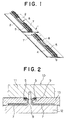
- fastener elements are removed from a predetermined number of prospective space portions (6), on each of which a separable bottom stop assembly 3 is to be mounted, of a fastener chain 1 composed of a pair of stringers 2, 2. Specifically, coupling heads are severed from the fastener elements 4 and the remaining fastener elements 4 are removed off sewing threads 5.
- the fastener elements are synthetic resin coiled fastener elements. Alternatively, they may be metallic fastener elements or injection molded synthetic resin fastener elements. It is essential that the fastener elements should be removed from the edge portions of the fastener tapes 7, irrespective of the type of fastener elements.
- the fastener elements 4 are removed from the fastener chain 1 to form the space portions 6, and then molten synthetic resin such as thermoplastic saturated polyester resin or polyurethane resin is impregnated into the entire area of each of the space portions 6 of the fastener chain 1.
- the space portions 6 are molded under heat and then hardened by a heating mold 10, such as shown in FIG. 2, in such a manner that the tape edge portions on which the sewing threads 5 are remaining are turned over into a U shape, as turns 9, to conform with the folded portions of the remaining stringers 2, 2 where the fastener elements 4 are mounted.
- the heating mold 10 is composed of an upper die 11, a lower die 12 and slide dies 13.
- a second pin member 14 of the separable bottom stop assembly 3 is injection molded, as shown in FIG. 4, on the tape edge portion of one stringer 2 by an injection mold 15, which is composed of an upper die 16, a lower die 17 and an orifice 18 as shown in FIG. 6.
- an injection mold 15 which is composed of an upper die 16, a lower die 17 and an orifice 18 as shown in FIG. 6.
- the tape edge portion at the space portion 6 will restore the U shape as indicated by phantom lines in FIG. 4.
- a box member 19 of the separable bottom stop assembly 3 such as shown in FIG. 5 is injection molded; the box member 19 has a unitary structure in which a first pin member 20 and a box 21 are integrally formed.
- this box member 19 has a two-piece structure in which a first pin member 22 and a box 23 are formed separately from each other.
- the first pin member 22 in injection molded on one tape edge portion, having on one end locking hooks 24.
- the box 23 to be locked with the first pin member 22 has catching portions 26 to be engaged with the locking hooks 24 on the inside wall of a hole 25 to which the first pin member 22 is to be inserted.
- the fastener chain 1 is sewn to a garment 28 contiguously to the first pin member 22 at the element-free portion by a sewing machine 27 of FIG. 8
- the first pin member 22 is threaded into the hole 25 until the locking hooks 24 are caught by the catching portions 26 so that the box 23 is fixed to the first pin member 22 to constitute the box member 19 of the separable bottom stop assembly 3.
- the sewing machine 27 comprises a table 29, a pressure foot 30 and a sewing needle 31, the pressure foot 30 having a pair of inclined guide grooves 32 in the surface confronting the table 29 for guiding the fastener elements 4, the second pin member 14 and the first pin member 22.
- 33 in FIG. 3 designates a slider.
- the separable bottom stop assembly molding method of this invention has the following results.
- the separable bottom stop assembly molding method comprises removing fastener elements 4 from a predetermined number of portions of a concealed slide fastener chain 1 to form a space portion 6, impregnating molten synthetic resin in fastener tapes 7 at areas around the space portion 6, heat-molding and hardening the tapes 7 in such a manner that confronting edge portions of the tapes 7 are turned over, cutting the tapes 7 across the space portion 6; injection molding a second pin member 14 of the separable bottom stop assembly 3 on the edge portion of one tape 7 and a box member 19 of the separable bottom stop assembly 3 on the edge of the other tape 7 at the space portion 6, contiguously to the fastener elements 4.
- molten synthetic resin is impregnated in the fastener chain's element-free portions, to which the separable bottom assembly 3 is to be attached, before heat-molding, it is possible to turn over the tape edge portions accurately and easily.
- the tapes 7 of the element-free portions can be treated so as to have a thickness equal to that of the remaining portions of the stringers 2 and so as to have an adequate degree of hardness, the second pin member 14 and the box member 19, or the first pin member 22 can be injection molded at a precise position. Accordingly there is no fear that inferior products might be obtained, facilitating the manufacturing of separable concealed slide fasteners.
Landscapes
- Engineering & Computer Science (AREA)
- Mechanical Engineering (AREA)
- Slide Fasteners (AREA)
- Injection Moulding Of Plastics Or The Like (AREA)
Applications Claiming Priority (2)
| Application Number | Priority Date | Filing Date | Title |
|---|---|---|---|
| JP38582/93 | 1993-02-26 | ||
| JP5038582A JPH06245806A (ja) | 1993-02-26 | 1993-02-26 | 隠しスライドファスナーの開離嵌挿具装着成形方法 |
Publications (2)
| Publication Number | Publication Date |
|---|---|
| EP0612487A1 true EP0612487A1 (de) | 1994-08-31 |
| EP0612487B1 EP0612487B1 (de) | 1998-04-15 |
Family
ID=12529291
Family Applications (1)
| Application Number | Title | Priority Date | Filing Date |
|---|---|---|---|
| EP94102422A Expired - Lifetime EP0612487B1 (de) | 1993-02-26 | 1994-02-17 | Verfahren zum Eingiessen von einem trennbaren unteren Endanschlag auf einen verdeckten Reissverschluss |
Country Status (8)
| Country | Link |
|---|---|
| US (1) | US5470516A (de) |
| EP (1) | EP0612487B1 (de) |
| JP (1) | JPH06245806A (de) |
| KR (1) | KR960001553B1 (de) |
| CA (1) | CA2116390C (de) |
| DE (1) | DE69409559D1 (de) |
| HK (1) | HK1006489A1 (de) |
| TW (1) | TW230189B (de) |
Cited By (2)
| Publication number | Priority date | Publication date | Assignee | Title |
|---|---|---|---|---|
| EP1321061A2 (de) * | 2001-12-21 | 2003-06-25 | Ykk Corporation | Trennbarer unterer Endanschlag für Reissverschlüsse und Herstellungsverfahren |
| EP1330967A1 (de) * | 2002-01-25 | 2003-07-30 | Ykk Corporation | Verdeckter Reissverschluss mit trennbarem unterem Endanschlag |
Families Citing this family (6)
| Publication number | Priority date | Publication date | Assignee | Title |
|---|---|---|---|---|
| DE4442080C2 (de) * | 1994-11-25 | 1997-05-22 | Bruss Dichtungstechnik | Verfahren zum Herstellen einer Dichtung für bewegte Bauteile und mit dem Verfahren hergestellte Dichtung |
| US6079085A (en) * | 1999-07-14 | 2000-06-27 | Chung; Roger C. Y. | Invisible zip fastener with double open end |
| CN101766376B (zh) * | 2010-02-09 | 2011-12-28 | 江门市多快好省机械有限公司 | 一种装饰性拉链的制作方法 |
| ES2646962T3 (es) | 2011-01-26 | 2017-12-18 | Ykk Corporation | Cadena de cierre de cremallera con tope terminal inferior separable y procedimiento para producir dicha cadena de cierre de cremallera |
| DE112017007677B4 (de) * | 2017-06-22 | 2023-05-04 | Ykk Corporation | Reißverschluss |
| CN112075728A (zh) * | 2020-09-18 | 2020-12-15 | 开易(广东)服装配件有限公司 | 第二种改进的链带、拉链、蒙皮用具及其形成方法 |
Citations (6)
| Publication number | Priority date | Publication date | Assignee | Title |
|---|---|---|---|---|
| JPS514816A (ja) * | 1974-06-10 | 1976-01-16 | Kyokado Eng Co | Yakuekichunyukoho |
| FR2401758A1 (fr) * | 1977-09-15 | 1979-03-30 | Horlacher Hans | Dispositif de positionnement des galons de fermetures a glissiere dans un moule de fabrication de telles fermetures |
| EP0021192A1 (de) * | 1979-06-21 | 1981-01-07 | Yoshida Kogyo K.K. | Trennbarer Reissverschluss |
| EP0158837A1 (de) * | 1984-03-15 | 1985-10-23 | Yoshida Kogyo K.K. | Trennbarer Reissverschluss |
| EP0160983A2 (de) * | 1984-05-10 | 1985-11-13 | Yoshida Kogyo K.K. | Verfahren und Vorrichtung zum Herstellen von Reissverschlüssen mit trennbaren Endgliedern |
| EP0368170A1 (de) * | 1988-11-08 | 1990-05-16 | Ykk Corporation | Trennbarer Reissverschluss |
Family Cites Families (10)
| Publication number | Priority date | Publication date | Assignee | Title |
|---|---|---|---|---|
| US1813433A (en) * | 1927-03-16 | 1931-07-07 | Hookless Fastener Co | Separable fastener |
| US3103728A (en) * | 1957-11-25 | 1963-09-17 | Wahl Brothers | Technique for assembling slide fasteners |
| BE602478A (fr) * | 1961-04-12 | 1961-07-31 | Berler Wilhelm | Perfectionnements aux organes de fermetures à curseurs |
| FR2055905A5 (de) * | 1969-08-06 | 1971-05-14 | Fflb | |
| US4034445A (en) * | 1975-07-28 | 1977-07-12 | Textron, Inc. | Molded top stop and apparatus and method of manufacture |
| JPS6239710Y2 (de) * | 1981-05-07 | 1987-10-09 | ||
| JPS5950312U (ja) * | 1982-09-27 | 1984-04-03 | ワイケイケイ株式会社 | 開離嵌挿具付スライドファスナー |
| JPS59120906U (ja) * | 1983-02-02 | 1984-08-15 | ワイケイケイ株式会社 | スライドフアスナ−の開離嵌挿具 |
| JPS6044130A (ja) * | 1983-08-23 | 1985-03-09 | Hitachi Metals Ltd | ロ−ルによる管の製造法 |
| EP0356600B1 (de) * | 1988-07-15 | 1993-04-07 | Opti Patent-, Forschungs- und Fabrikations-AG | Verfahren und Vorrichtung zur Herstellung von Reissverschlüssen |
-
1993
- 1993-02-26 JP JP5038582A patent/JPH06245806A/ja active Pending
-
1994
- 1994-02-16 US US08/197,328 patent/US5470516A/en not_active Expired - Fee Related
- 1994-02-17 DE DE69409559T patent/DE69409559D1/de not_active Expired - Lifetime
- 1994-02-17 EP EP94102422A patent/EP0612487B1/de not_active Expired - Lifetime
- 1994-02-24 CA CA002116390A patent/CA2116390C/en not_active Expired - Fee Related
- 1994-02-25 KR KR1019940003635A patent/KR960001553B1/ko not_active IP Right Cessation
- 1994-02-26 TW TW083101725A patent/TW230189B/zh active
-
1998
- 1998-06-18 HK HK98105646A patent/HK1006489A1/xx not_active IP Right Cessation
Patent Citations (6)
| Publication number | Priority date | Publication date | Assignee | Title |
|---|---|---|---|---|
| JPS514816A (ja) * | 1974-06-10 | 1976-01-16 | Kyokado Eng Co | Yakuekichunyukoho |
| FR2401758A1 (fr) * | 1977-09-15 | 1979-03-30 | Horlacher Hans | Dispositif de positionnement des galons de fermetures a glissiere dans un moule de fabrication de telles fermetures |
| EP0021192A1 (de) * | 1979-06-21 | 1981-01-07 | Yoshida Kogyo K.K. | Trennbarer Reissverschluss |
| EP0158837A1 (de) * | 1984-03-15 | 1985-10-23 | Yoshida Kogyo K.K. | Trennbarer Reissverschluss |
| EP0160983A2 (de) * | 1984-05-10 | 1985-11-13 | Yoshida Kogyo K.K. | Verfahren und Vorrichtung zum Herstellen von Reissverschlüssen mit trennbaren Endgliedern |
| EP0368170A1 (de) * | 1988-11-08 | 1990-05-16 | Ykk Corporation | Trennbarer Reissverschluss |
Cited By (5)
| Publication number | Priority date | Publication date | Assignee | Title |
|---|---|---|---|---|
| EP1321061A2 (de) * | 2001-12-21 | 2003-06-25 | Ykk Corporation | Trennbarer unterer Endanschlag für Reissverschlüsse und Herstellungsverfahren |
| EP1321061A3 (de) * | 2001-12-21 | 2004-06-16 | Ykk Corporation | Trennbarer unterer Endanschlag für Reissverschlüsse und Herstellungsverfahren |
| US6865782B2 (en) | 2001-12-21 | 2005-03-15 | Ykk Corporation | Slide fastener with separable bottom stop assembly and method of manufacturing the same |
| EP1330967A1 (de) * | 2002-01-25 | 2003-07-30 | Ykk Corporation | Verdeckter Reissverschluss mit trennbarem unterem Endanschlag |
| US6851162B2 (en) | 2002-01-25 | 2005-02-08 | Ykk Corporation | Concealed type slide fastener with separable bottom end stop |
Also Published As
| Publication number | Publication date |
|---|---|
| KR960001553B1 (ko) | 1996-02-02 |
| TW230189B (de) | 1994-09-11 |
| CA2116390C (en) | 1998-01-06 |
| JPH06245806A (ja) | 1994-09-06 |
| CA2116390A1 (en) | 1994-08-27 |
| HK1006489A1 (en) | 1999-02-26 |
| EP0612487B1 (de) | 1998-04-15 |
| US5470516A (en) | 1995-11-28 |
| DE69409559D1 (de) | 1998-05-20 |
| KR940019259A (ko) | 1994-09-14 |
Similar Documents
| Publication | Publication Date | Title |
|---|---|---|
| CA1076328A (en) | Slide fastener with molded top stops and method of manufacture | |
| KR100503865B1 (ko) | 개방이탈 삽입구가 부착된 은폐형 슬라이드 파스너 | |
| US5470516A (en) | Method of molding a separable bottom stop assembly on a concealed slide fastener | |
| US4658480A (en) | Fluid-tight slide fastener | |
| US4312103A (en) | Separable slide fastener | |
| JP3589442B2 (ja) | ファスナーテープの開離嵌挿具取付部 | |
| US7137177B2 (en) | Top end stop of linear slide fastener | |
| EP1537801B1 (de) | Verfahren zur Herstellung eines Gleitverschlusses | |
| US5359754A (en) | Top end stop for concealed slide fastener | |
| CA2091924C (en) | Slider for slide fastener with automatic stop means | |
| US5913481A (en) | Separable slide fastener | |
| GB2289917A (en) | Lock slider for slide fastener | |
| US6314622B1 (en) | Engaging member of fastening device | |
| US3605208A (en) | Molded clasp for slide fasteners | |
| US4380098A (en) | Slide fastener stringer | |
| US4858284A (en) | Separable bottom end stop for slide fastener | |
| US4182006A (en) | Slide fastener stringer | |
| CA1066492A (en) | Process and apparatus for manufacturing slide fastener stringer | |
| US4187591A (en) | Continuous slide fastener stringers | |
| CA1103903A (en) | Slide fastener stringer | |
| US4232432A (en) | Separable slide fastener | |
| US4675950A (en) | Slide fastener suitable for use on articles made of plastics material | |
| JPS5925222Y2 (ja) | スライドフアスナ−用下止具 | |
| US4237806A (en) | Installation of separable slide fastener on article | |
| GB2032998A (en) | A separable slide fastener |
Legal Events
| Date | Code | Title | Description |
|---|---|---|---|
| PUAI | Public reference made under article 153(3) epc to a published international application that has entered the european phase |
Free format text: ORIGINAL CODE: 0009012 |
|
| AK | Designated contracting states |
Kind code of ref document: A1 Designated state(s): DE ES FR GB IT |
|
| RAP1 | Party data changed (applicant data changed or rights of an application transferred) |
Owner name: YKK CORPORATION |
|
| 17P | Request for examination filed |
Effective date: 19941128 |
|
| 17Q | First examination report despatched |
Effective date: 19960726 |
|
| GRAG | Despatch of communication of intention to grant |
Free format text: ORIGINAL CODE: EPIDOS AGRA |
|
| GRAG | Despatch of communication of intention to grant |
Free format text: ORIGINAL CODE: EPIDOS AGRA |
|
| GRAG | Despatch of communication of intention to grant |
Free format text: ORIGINAL CODE: EPIDOS AGRA |
|
| GRAH | Despatch of communication of intention to grant a patent |
Free format text: ORIGINAL CODE: EPIDOS IGRA |
|
| GRAH | Despatch of communication of intention to grant a patent |
Free format text: ORIGINAL CODE: EPIDOS IGRA |
|
| GRAA | (expected) grant |
Free format text: ORIGINAL CODE: 0009210 |
|
| AK | Designated contracting states |
Kind code of ref document: B1 Designated state(s): DE ES FR GB IT |
|
| PG25 | Lapsed in a contracting state [announced via postgrant information from national office to epo] |
Ref country code: IT Free format text: LAPSE BECAUSE OF FAILURE TO SUBMIT A TRANSLATION OF THE DESCRIPTION OR TO PAY THE FEE WITHIN THE PRE;WARNING: LAPSES OF ITALIAN PATENTS WITH EFFECTIVE DATE BEFORE 2007 MAY HAVE OCCURRED AT ANY TIME BEFORE 2007. THE CORRECT EFFECTIVE DATE MAY BE DIFFERENT FROM THE ONE RECORDED.SCRIBED TIME-LIMIT Effective date: 19980415 Ref country code: FR Free format text: LAPSE BECAUSE OF FAILURE TO SUBMIT A TRANSLATION OF THE DESCRIPTION OR TO PAY THE FEE WITHIN THE PRESCRIBED TIME-LIMIT Effective date: 19980415 Ref country code: ES Free format text: THE PATENT HAS BEEN ANNULLED BY A DECISION OF A NATIONAL AUTHORITY Effective date: 19980415 |
|
| REF | Corresponds to: |
Ref document number: 69409559 Country of ref document: DE Date of ref document: 19980520 |
|
| PG25 | Lapsed in a contracting state [announced via postgrant information from national office to epo] |
Ref country code: DE Free format text: LAPSE BECAUSE OF FAILURE TO SUBMIT A TRANSLATION OF THE DESCRIPTION OR TO PAY THE FEE WITHIN THE PRESCRIBED TIME-LIMIT Effective date: 19980716 |
|
| EN | Fr: translation not filed | ||
| PLBE | No opposition filed within time limit |
Free format text: ORIGINAL CODE: 0009261 |
|
| STAA | Information on the status of an ep patent application or granted ep patent |
Free format text: STATUS: NO OPPOSITION FILED WITHIN TIME LIMIT |
|
| 26N | No opposition filed | ||
| REG | Reference to a national code |
Ref country code: GB Ref legal event code: IF02 |
|
| PGFP | Annual fee paid to national office [announced via postgrant information from national office to epo] |
Ref country code: GB Payment date: 20050216 Year of fee payment: 12 |
|
| PG25 | Lapsed in a contracting state [announced via postgrant information from national office to epo] |
Ref country code: GB Free format text: LAPSE BECAUSE OF NON-PAYMENT OF DUE FEES Effective date: 20060217 |
|
| GBPC | Gb: european patent ceased through non-payment of renewal fee |
Effective date: 20060217 |