EP0612288B1 - Vented removable cap - Google Patents
Vented removable cap Download PDFInfo
- Publication number
- EP0612288B1 EP0612288B1 EP92925129A EP92925129A EP0612288B1 EP 0612288 B1 EP0612288 B1 EP 0612288B1 EP 92925129 A EP92925129 A EP 92925129A EP 92925129 A EP92925129 A EP 92925129A EP 0612288 B1 EP0612288 B1 EP 0612288B1
- Authority
- EP
- European Patent Office
- Prior art keywords
- circumferential
- inner cap
- hub
- cap member
- circumferential hub
- Prior art date
- Legal status (The legal status is an assumption and is not a legal conclusion. Google has not performed a legal analysis and makes no representation as to the accuracy of the status listed.)
- Expired - Lifetime
Links
- 230000002093 peripheral effect Effects 0.000 claims description 10
- 238000007789 sealing Methods 0.000 claims description 4
- 230000000153 supplemental effect Effects 0.000 claims description 4
- 239000000853 adhesive Substances 0.000 claims description 3
- 230000001070 adhesive effect Effects 0.000 claims description 3
- 238000003780 insertion Methods 0.000 claims description 3
- 230000037431 insertion Effects 0.000 claims description 3
- 238000004891 communication Methods 0.000 description 5
- 230000008020 evaporation Effects 0.000 description 4
- 238000001704 evaporation Methods 0.000 description 4
- 239000000725 suspension Substances 0.000 description 3
- 238000010276 construction Methods 0.000 description 2
- 230000000694 effects Effects 0.000 description 2
- 238000004519 manufacturing process Methods 0.000 description 2
- 238000000034 method Methods 0.000 description 2
- 238000007796 conventional method Methods 0.000 description 1
- 238000013461 design Methods 0.000 description 1
- 238000000465 moulding Methods 0.000 description 1
Images





Classifications
-
- B—PERFORMING OPERATIONS; TRANSPORTING
- B43—WRITING OR DRAWING IMPLEMENTS; BUREAU ACCESSORIES
- B43K—IMPLEMENTS FOR WRITING OR DRAWING
- B43K23/00—Holders or connectors for writing implements; Means for protecting the writing-points
- B43K23/08—Protecting means, e.g. caps
- B43K23/12—Protecting means, e.g. caps for pens
- B43K23/122—Protecting means, e.g. caps for pens with means for preventing choking
- B43K23/124—Protecting means, e.g. caps for pens with means for preventing choking comprising an air passage
Definitions
- the present invention relates to removable caps for writing implements, and relates in particular, to a vented removable cap adapted to allow for the flow of air therethrough while engaging the nib or writing portion of the implement to prevent the evaporation of ink therefrom.
- Removable caps for writing implements which use ink are configured to enclose the writing or nib portion of the implement to prevent the evaporation of the ink therein as well as to protect the functional components.
- a conventional removable cap typically includes an outer cylindrical member having an inner cap disposed in the interior of the cylindrical member for receiving and forming an air tight seal around the writing portion of the implement.
- the removable cap has a double walled construction closed at a first end and open at a second end, where the inner cap and the outer cylindrical member are integrally formed as a single unit.
- removable caps which not only provides an adequate seal around the writing portion of an implement, but also permits air to flow axially through the interior of the cap when the cap is detached from the implement.
- Such removable caps typically include an outer hollow main body, an inner cap disposed within and secured to the main body, and interconnected apertures and/or spaces to establish the air passage. Examples of such configurations are described in U.S. Patent Nos. 5,000,603 to Isoda, 5,000,604 to Isoda, GB 2220199, and PCT Application WO 89/11978.
- a removable cap in U.S. Patent No. 5,000,603 to Isoda, includes an inner cylinder positioned within an outer cylindrical body.
- a plurality of ribs are provided on the outer peripheral surface of the inner cylinder to secure the inner cylinder to the outer body along its mid-length, and an outer flange is provided at the open end of the inner cylinder to secure the inner cylinder to the outer cylindrical body at its bottom portion also.
- a complex air passageway arrangement provides communication between the inner cavity and the external atmosphere.
- U.S. Patent No. 5,000,604 to Isoda discloses an inner cylinder for covering the tip of the writing instrument secured to a double-walled outer cylinder.
- the inner wall of the double-walled outer cylinder is provided with a plurality of axially directed slits, and the axially directed land portions between the slits are secured to the inner cylinder.
- Communication between the inner cavity and the external atmosphere is provided by the axially directed slits of the inner wall of the double-walled cylindrical outer body.
- British Patent Application GB 2220199 describes an outer cylindrical cap body having an inner cylinder positioned therein where the inner cylinder is secured to the outer cylinder at its open end. Air passage slots are provided adjacent the open end of the inner cylinder, and the slots are sealed by the body of the writing instrument when it is inserted into the cap. Upon removal of the body of the writing instrument, the air passage slots provide communication between the interior cavity of the cap and the outer atmosphere.
- PCT Application WO 89/11978 describes a pen cap having an outer cylindrical body with an inner cylinder mounted by axially directed land portions adjacent a bore hole at the closed end of the outer cylinder.
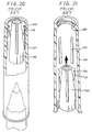
- a conically shaped inner cap 100 having a plurality of axially extending ribs 102 integrally molded with the inner cap is mounted within an outer tubular member 104.
- Each rib 102 possesses a groove 106 which locks with an annular rib 108 formed on the inner surface of the outer tubular member to effect the mounting.
- the axial extending ribs 102 directly abut the inner peripheral surface of the outer tubular member, and outer tubular member 104 also possesses raised portions 110 which are in contact with the peripheral surface of the inner cap.
- Air passage slots are provided between the axial ribs of the inner cap.
- each cap includes an inherently complex design, specifically with regard to the mounting of the inner cap to the main cap body which requires close tolerances during construction to prevent obstruction of the vent openings.
- the inner caps of these devices are supported by the main cap bodies along a substantial portion of the peripheral surfaces of the inner caps, such that any pivotal movement of the inner cap relative to the main cap body is minimized or eliminated, requiring precise molding and constructional tolerances. Consequently, if the inner cap is assembled in non-axial alignment relative to the main cap body, which may occur due to the precision in which the component parts are manufactured, the inner cap is not capable of adjusting its position relative to the main cap body to receive the writing portion of the implement.
- a removable cap for receiving a writing implement comprising a generally cylindrical member having an opening at one end for receiving the implement and a partial enclosure wall integrally formed with the cylindrical member at a second end.
- the partial enclosure wall comprises a closed circumferential hub having a central opening, the hub being concentric with the cylindrical member and including at least one radially extending rib projecting therefrom to secure the hub to the cylindrical member.
- the partial enclosure wall also includes at least one generally arcuately shaped opening surrounding the circumferential hub through which the interior of the cylindrical member communicates with external air.
- An inner cap member is mounted within the cylindrical member in general axial alignment therewith and includes an opening at one end and a closing wall at a second end for receiving and sealing a writing point of the implement.
- Mounting means are provided for suspendedly mounting the inner cap member adjacent its closed end within the central opening of the circumferential hub.
- the inner cap member includes a circumferential groove disposed adjacent the closed end of the inner cap member.
- the circumferential groove defines a head portion at the closed end of the inner cap member and terminates in a raised edge at a position adjacent a body portion of the inner cap member intermediate the open end of the inner cap member and the circumferential groove.
- the circumferential hub includes a ledge member disposed on an inner surface thereof, where the ledge member has an inner diameter that is less than the diameter of the head portion of the inner cap member.
- the ledge member may also include a beveled or tapered surface to facilitate insertion of the inner cap into the hub.
- the head portion of the inner cap is received within the central opening of the circumferential hub and engages with the ledge member of the hub to suspendedly mount the inner cap member.
- the inner diameter of the circumferential hub is less than the diameter of the raised edge of the inner cap member, so that once the inner cap member is mounted, the raised edge engages the end of the hub within the interior of the cylindrical member to retain the head portion within the circumferential hub.
- the beveled surface provided on the circumferential hub facilitates the insertion of the inner cap member within the hub during assembly.
- the inner cap member includes a circumferential groove with the raised edge eliminated and the circumferential hub includes a circumferential rib having a hemispherical cross-section. The groove and the rib interlock to suspendedly mount the inner cap member to the partial enclosure wall.
- the circumferential hub is provided with at least one outwardly projecting tab, while the inner cap member includes at least one corresponding recess which interlocks with the tab to mount the inner cap member to the hub.
- the circumferential hub is eliminated, and the partial enclosure wall comprises at least one radially projecting land portion which secures the inner cap directly to the land portion.
- the land portion defines at least one aperture through which the interior of the cylindrical member communicates with air external to the cap.
- the partial enclosure wall includes two land portions. The inner cap member may be suspendedly mounted to the land portions by any of the aforementioned means.
- the present invention is directed to a removable cap for a writing implement which effectively seals the writing portion of the implement to prevent the evaporation of ink therein while permitting air to axially flow through the interior of the cap when the cap is detached from the implement.
- the present invention is relatively simple to manufacture and assemble and facilitates adjustment of its axial alignment relative to the main cap body.
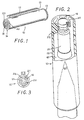
- FIGS. 1-4 illustrate a removable cap 10 in accordance with the present invention.
- Removable cap 10 is configured to detachably receive and enclose the writing or nib portion of a writing implement as shown in phantom in FIG. 2.
- Removable cap 10 includes main cap member 12 and inner cap member 14 which is suspendedly mounted to the main cap member.
- Main cap member 12 is preferably cylindrically shaped having an opening at a first end and a partial enclosure wall 16 integrally formed with member 12 at a second end.
- Inner cap member 14 is preferably generally cylindrically shaped, but may taper towards its closed end to receive and seal the writing portion of an implement in a generally frusto-conical shape.
- Partial enclosure wall 16 includes a circumferential hub 20 concentric with an outer wall of main cap 12 having a central opening 21, with six radially extending ribs 22 projecting from the hub. As shown in FIG. 4, ribs 22 also provide support and stability to hub 20 so that the hub can receive and secure inner cap 14 during assembly. Ribs 22 are shaped so as to define six arcuately shaped apertures or voids 18 surrounding hub 20, apertures 18 providing a passageway through which the interior of removable cap 10 communicates with external air when cap 10 is removed from the implement. It is to be appreciated that the number of ribs 22 and apertures 18 is not limited to six.
- Circumferential hub 20 is configured to receive and mount inner cap member 14 and includes a circumferential ledge member 24 projecting from the inner peripheral surface of the hub and disposed on the hub at a position intermediate the lower and upper edges of the hub.
- Ledge member 24 may also be positioned adjacent a lower edge of the hub.
- a beveled surface 26 extends from the ledge member 24 to a generally vertical surface 28 of hub 20.
- FIG. 5 illustrates an enlarged view of this surface in detail. As shown, vertical surface 28 extends to lower edge 30 of the hub.
- Inner cap member 14 includes a circumferential groove 32 disposed adjacent the closed end of the inner cap, groove 32 defining a head portion 34 on a first side of the groove and a stepped raised edge 36 on the second side, which extends from groove 32 to the remaining body portion of the inner cap.
- the diameter of head portion 34 is slightly less than the diameter of the inner peripheral surface of hub 20, but is larger than the inner diameter of circumferential ledge member 24. It is also preferable for the diameter of raised edge 36 to be larger than the diameter of circumferential hub 20 for reasons described below.
- inner cap 14 is inserted within main cap member 12, and is then advanced towards partial enclosure wall 16 (as shown in FIG. 4) with head portion 34 engaging beveled surface 26 of hub 20.
- the tapering feature of bevel surface guides head portion 34 through circumferential hub 20, wherein head portion 34 is forcibly inserted through the circumferential hub 20 until the lower edge of head portion 34 clears beveled surface 26 and rests on circumferential ledge 24.
- inner cap 14 is suspendedly mounted to partial enclosure wall 16 by the engagement of the lower edge of head portion 34 with circumferential ledge member 24. Head portion 34 is also maintained within hub 20 by the engagement of stepped raised edge 36 of inner cap 14 with the lower edge 30 of the circumferential hub.
- inner cap 14 is suspendedly mounted to main cap member 12 by the engagement of circumferential hub 20 with head portion 34 of the inner cap 14.
- the mounting means of the present invention mounts inner cap 14 in general axial alignment with main cap member 12.
- the mounting means of the present invention allows for slight pivotal movement of inner cap 14 relative to the main cap body. This is made possible since the inner cap is mounted in suspension at its closed end to the main cap member, while there is no other contact between the remaining portion of the inner cap member 14 with the main cap member 12.
- This is a feature of the present invention and finds application when component dimensions are not met with precision during manufacture and the inner cap in its assembled position is not aligned with the central axis of the main cap member. In such situations, as the writing portion of the implement enters the inner cap, the inner cap pivots around its mounted head portion 34 to receive the writing point of the implement and realign its position relative to the main cap member.
- removable cap 10 in its assembled condition provides a passageway for air to flow through the cap when the cap is detached from the implement.
- Arcuately shaped apertures 18 of partial enclosure wall 16 are in communication with a channel 40 defined between the outer peripheral surface of inner cap member 14 and the inner peripheral surface of the main cap member 12.
- Channel 40 is in direct communication with the open end of main cap member 12.
- inner cap member 14 encloses and seals the writing portion of the implement, thereby preventing evaporation of ink and protecting the functional components of the implement from damage.
- Removable cap 10 may be detachably mounted to the implement by conventional methods.
- FIGS. 6-8 illustrate an alternate embodiment of the removable cap of the present invention.
- ribs 22 are longer in length than the ribs of the embodiment of FIG. 2 and, as such, extend further axially along main cap member 12. This feature provides additional support and stability to circumferential hub 20.
- Inner cap 14 tapers to form a frusto-conical shape, to correspond with the tapering of the writing portion to be received.
- Inner cap 14 includes circumferential groove 42 forming raised edge 44 on the body portion side of the groove. When head portion 34 of inner cap 14 is mounted onto ledge member 24 of circumferential hub 20, raised edge 44 abuts the lower edge 30 of hub 20 to retain the inner cap within the circumferential hub.
- the embodiment of FIGS. 6-8 is similar in all other respects to the embodiment of FIGS. 1-5.
- FIGS. 9-11 illustrate another embodiment of the removable cap 10 of FIG. 1, in which a supplemental rib 23 is provided between each rib 22. Supplemental ribs 23 provide even further support to circumferential hub 20 and are integrally formed with the inner peripheral surface of main cap member 12 and the interior or lower portion of hub 20.
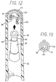
- FIGS. 12 and 13 illustrate a further embodiment of the present invention.
- circumferential hub 20 possesses only one radial rib 22, which defines one arcuately shaped aperture 18.
- Radial rib 22 is dimensioned and configured to support circumferential hub 20 and inner cap 14 after assembly as best seen in FIG. 13.
- circumferential hub 20 may be provided with a hemispherically shaped circumferential rib 46 and the inner cap 14 may possess a circumferential groove 48 adjacent its closed end which interlocks with rib 46 to mount the inner cap member to the hub.
- circumferential hub 20 may be provided with a plurality of tabs 52 which interlock with corresponding slots or recesses 54 provided in the inner cap to mount the inner cap member as shown in FIG. 15. Slots 54 do not penetrate through cap 14, in order to maintain the air-tightness within cap 14 when a writing implement is positioned therein. It is also possible to mount inner cap member 14 to circumferential hub 20 by adhesive means.
- circumferential hub 20 is replaced by two land portions 56, land portions 56 having engaging surfaces 60.
- Land portions 56 define two apertures 58 in the enclosing wall as best seen in FIG. 17.
- Inner cap 14 may be mounted in suspension to land portions 56 by any of the aforementioned methods.
- engaging surfaces 60 of land portions 56 may include tabs 62 which interlock with slots 64 provided in inner cap 14 to mount the inner cap in suspension to main cap member 12.
- land portions 56 may include an arcuate hemispherically shaped rib 66 which interlocks with an arcuate groove 68 in the inner cap to effect the mounting as shown in FIG. 19.
- inner cap 14 may be mounted by adhesive means, as in FIG. 16.
Landscapes
- Pens And Brushes (AREA)
- Closures For Containers (AREA)
- Turbine Rotor Nozzle Sealing (AREA)
- Light Receiving Elements (AREA)
- Containers And Packaging Bodies Having A Special Means To Remove Contents (AREA)
- Prevention Of Fouling (AREA)
- Outer Garments And Coats (AREA)
- Coating Apparatus (AREA)
Abstract
Description
- The present invention relates to removable caps for writing implements, and relates in particular, to a vented removable cap adapted to allow for the flow of air therethrough while engaging the nib or writing portion of the implement to prevent the evaporation of ink therefrom.
- Removable caps for writing implements which use ink are configured to enclose the writing or nib portion of the implement to prevent the evaporation of the ink therein as well as to protect the functional components. A conventional removable cap typically includes an outer cylindrical member having an inner cap disposed in the interior of the cylindrical member for receiving and forming an air tight seal around the writing portion of the implement. In one known type, the removable cap has a double walled construction closed at a first end and open at a second end, where the inner cap and the outer cylindrical member are integrally formed as a single unit.
- Recently, it has become desirable to construct a removable cap which not only provides an adequate seal around the writing portion of an implement, but also permits air to flow axially through the interior of the cap when the cap is detached from the implement. Such removable caps typically include an outer hollow main body, an inner cap disposed within and secured to the main body, and interconnected apertures and/or spaces to establish the air passage. Examples of such configurations are described in U.S. Patent Nos. 5,000,603 to Isoda, 5,000,604 to Isoda, GB 2220199, and PCT Application WO 89/11978.
- In U.S. Patent No. 5,000,603 to Isoda, a removable cap includes an inner cylinder positioned within an outer cylindrical body. A plurality of ribs are provided on the outer peripheral surface of the inner cylinder to secure the inner cylinder to the outer body along its mid-length, and an outer flange is provided at the open end of the inner cylinder to secure the inner cylinder to the outer cylindrical body at its bottom portion also. A complex air passageway arrangement provides communication between the inner cavity and the external atmosphere.
- U.S. Patent No. 5,000,604 to Isoda discloses an inner cylinder for covering the tip of the writing instrument secured to a double-walled outer cylinder. The inner wall of the double-walled outer cylinder is provided with a plurality of axially directed slits, and the axially directed land portions between the slits are secured to the inner cylinder. Communication between the inner cavity and the external atmosphere is provided by the axially directed slits of the inner wall of the double-walled cylindrical outer body.
- British Patent Application GB 2220199 describes an outer cylindrical cap body having an inner cylinder positioned therein where the inner cylinder is secured to the outer cylinder at its open end. Air passage slots are provided adjacent the open end of the inner cylinder, and the slots are sealed by the body of the writing instrument when it is inserted into the cap. Upon removal of the body of the writing instrument, the air passage slots provide communication between the interior cavity of the cap and the outer atmosphere.
- PCT Application WO 89/11978 describes a pen cap having an outer cylindrical body with an inner cylinder mounted by axially directed land portions adjacent a bore hole at the closed end of the outer cylinder.
- Another known type of vented removable cap is illustrated in Figs. 20 and 21 of the drawings. In accordance with this device, a conically shaped
inner cap 100 having a plurality of axially extendingribs 102 integrally molded with the inner cap is mounted within an outertubular member 104. Eachrib 102 possesses agroove 106 which locks with anannular rib 108 formed on the inner surface of the outer tubular member to effect the mounting. The axial extendingribs 102 directly abut the inner peripheral surface of the outer tubular member, and outertubular member 104 also possesses raisedportions 110 which are in contact with the peripheral surface of the inner cap. Air passage slots are provided between the axial ribs of the inner cap. - Although these caps are effective in sealing the writing portion of the implement and also incorporate provisions to enable external air to flow through the interior of the cap when the cap is detached from the implement, these devices present a number of disadvantages. For example, each cap includes an inherently complex design, specifically with regard to the mounting of the inner cap to the main cap body which requires close tolerances during construction to prevent obstruction of the vent openings. Furthermore, the inner caps of these devices are supported by the main cap bodies along a substantial portion of the peripheral surfaces of the inner caps, such that any pivotal movement of the inner cap relative to the main cap body is minimized or eliminated, requiring precise molding and constructional tolerances. Consequently, if the inner cap is assembled in non-axial alignment relative to the main cap body, which may occur due to the precision in which the component parts are manufactured, the inner cap is not capable of adjusting its position relative to the main cap body to receive the writing portion of the implement.
- A removable cap for receiving a writing implement is provided, comprising a generally cylindrical member having an opening at one end for receiving the implement and a partial enclosure wall integrally formed with the cylindrical member at a second end. The partial enclosure wall comprises a closed circumferential hub having a central opening, the hub being concentric with the cylindrical member and including at least one radially extending rib projecting therefrom to secure the hub to the cylindrical member. The partial enclosure wall also includes at least one generally arcuately shaped opening surrounding the circumferential hub through which the interior of the cylindrical member communicates with external air. An inner cap member is mounted within the cylindrical member in general axial alignment therewith and includes an opening at one end and a closing wall at a second end for receiving and sealing a writing point of the implement. Mounting means are provided for suspendedly mounting the inner cap member adjacent its closed end within the central opening of the circumferential hub.
- In one preferred embodiment, the inner cap member includes a circumferential groove disposed adjacent the closed end of the inner cap member. The circumferential groove defines a head portion at the closed end of the inner cap member and terminates in a raised edge at a position adjacent a body portion of the inner cap member intermediate the open end of the inner cap member and the circumferential groove. The circumferential hub includes a ledge member disposed on an inner surface thereof, where the ledge member has an inner diameter that is less than the diameter of the head portion of the inner cap member. The ledge member may also include a beveled or tapered surface to facilitate insertion of the inner cap into the hub.
- In assembly, the head portion of the inner cap is received within the central opening of the circumferential hub and engages with the ledge member of the hub to suspendedly mount the inner cap member. Furthermore, the inner diameter of the circumferential hub is less than the diameter of the raised edge of the inner cap member, so that once the inner cap member is mounted, the raised edge engages the end of the hub within the interior of the cylindrical member to retain the head portion within the circumferential hub. The beveled surface provided on the circumferential hub facilitates the insertion of the inner cap member within the hub during assembly.
- In an alternative embodiment, the inner cap member includes a circumferential groove with the raised edge eliminated and the circumferential hub includes a circumferential rib having a hemispherical cross-section. The groove and the rib interlock to suspendedly mount the inner cap member to the partial enclosure wall. In another embodiment, the circumferential hub is provided with at least one outwardly projecting tab, while the inner cap member includes at least one corresponding recess which interlocks with the tab to mount the inner cap member to the hub.
- In accordance with another embodiment of the present invention, the circumferential hub is eliminated, and the partial enclosure wall comprises at least one radially projecting land portion which secures the inner cap directly to the land portion. The land portion defines at least one aperture through which the interior of the cylindrical member communicates with air external to the cap. Preferably, the partial enclosure wall includes two land portions. The inner cap member may be suspendedly mounted to the land portions by any of the aforementioned means.
- The present invention is directed to a removable cap for a writing implement which effectively seals the writing portion of the implement to prevent the evaporation of ink therein while permitting air to axially flow through the interior of the cap when the cap is detached from the implement. The present invention is relatively simple to manufacture and assemble and facilitates adjustment of its axial alignment relative to the main cap body.
- Preferred embodiments of the invention are described hereinbelow wherein:
- FIG. 1 is a perspective view of the removable cap of the present invention;
- FIG. 2 is a perspective view in partial cross-section of a longitudinal section of the removable cap of FIG. 1;
- FIG. 3 is an end view of the removable cap of FIG. 1;
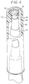
- FIG. 4 is a perspective cross-sectional view of a longitudinal section of the removable cap of FIG. 2 prior to assembly;
- FIG. 5 is an enlarged cross-sectional view of the mounting surface of a circumferential hub of the removable cap of FIG. 1;
- FIG. 6 is a perspective view in partial cross-section of a longitudinal section of an alternative embodiment of the present invention;
- FIG. 7 is a perspective cross-sectional view of a longitudinal section of the embodiment of FIG. 6 prior to assembly;
- FIG. 8 is an enlarged cross-sectional view of the mounting surface of the circumferential hub of the embodiment of FIG. 6;
- FIG. 9 is a perspective view in partial cross-section of a longitudinal section of another embodiment of the present invention;
- FIG. 10 is a perspective cross-sectional view of the longitudinal section of the embodiment of FIG. 9 prior to assembly;
- FIG. 11 is an end view of the embodiment of FIG. 9;
- FIG. 12 is a perspective cross-sectional view of a longitudinal section of another embodiment of the present invention prior to assembly;
- FIG. 13 is an end view of the embodiment of FIG. 12;
- FIG. 14 is a perspective cross-sectional view of a longitudinal section of still another embodiment of the present invention prior to assembly;
- FIG. 15 is a perspective cross-sectional view of a longitudinal section of a further embodiment of the present invention prior to assembly;
- FIG. 16 is a perspective cross-sectional view of a longitudinal section of another embodiment of the present invention prior to assembly;
- FIG. 17 is an end view of the embodiment of FIG. 16;
- FIG. 18 is a perspective cross-sectional view of a longitudinal section of yet another embodiment of the present invention prior to assembly;
- FIG. 19 is a perspective cross-sectional view of a longitudinal section of a further embodiment of the present invention prior to assembly;
- FIG. 20 is a perspective view in partial cross-section of a longitudinal section of a conventional removable cap; and
- FIG. 21 is a perspective cross-sectional view of a longitudinal section of the convention removable cap of FIG. 20 prior to assembly.
- Referring now in specific detail to the drawings, in which like reference numerals identify similar or identical elements throughout the several views, FIGS. 1-4 illustrate a
removable cap 10 in accordance with the present invention.Removable cap 10 is configured to detachably receive and enclose the writing or nib portion of a writing implement as shown in phantom in FIG. 2. -
Removable cap 10 includesmain cap member 12 andinner cap member 14 which is suspendedly mounted to the main cap member.Main cap member 12 is preferably cylindrically shaped having an opening at a first end and apartial enclosure wall 16 integrally formed withmember 12 at a second end.Inner cap member 14 is preferably generally cylindrically shaped, but may taper towards its closed end to receive and seal the writing portion of an implement in a generally frusto-conical shape. -
Partial enclosure wall 16 includes acircumferential hub 20 concentric with an outer wall ofmain cap 12 having acentral opening 21, with six radially extendingribs 22 projecting from the hub. As shown in FIG. 4,ribs 22 also provide support and stability tohub 20 so that the hub can receive and secureinner cap 14 during assembly.Ribs 22 are shaped so as to define six arcuately shaped apertures or voids 18 surroundinghub 20,apertures 18 providing a passageway through which the interior ofremovable cap 10 communicates with external air whencap 10 is removed from the implement. It is to be appreciated that the number ofribs 22 andapertures 18 is not limited to six. - Referring now to FIGS. 4 and 5, the mounting means for securing the
inner cap member 14 tomain cap member 12 is illustrated.Circumferential hub 20 is configured to receive and mountinner cap member 14 and includes acircumferential ledge member 24 projecting from the inner peripheral surface of the hub and disposed on the hub at a position intermediate the lower and upper edges of the hub.Ledge member 24 may also be positioned adjacent a lower edge of the hub. Abeveled surface 26 extends from theledge member 24 to a generallyvertical surface 28 ofhub 20. FIG. 5 illustrates an enlarged view of this surface in detail. As shown,vertical surface 28 extends tolower edge 30 of the hub. -
Inner cap member 14 includes acircumferential groove 32 disposed adjacent the closed end of the inner cap, groove 32 defining ahead portion 34 on a first side of the groove and a stepped raisededge 36 on the second side, which extends fromgroove 32 to the remaining body portion of the inner cap. The diameter ofhead portion 34 is slightly less than the diameter of the inner peripheral surface ofhub 20, but is larger than the inner diameter ofcircumferential ledge member 24. It is also preferable for the diameter of raisededge 36 to be larger than the diameter ofcircumferential hub 20 for reasons described below. - In assembly,
inner cap 14 is inserted withinmain cap member 12, and is then advanced towards partial enclosure wall 16 (as shown in FIG. 4) withhead portion 34 engagingbeveled surface 26 ofhub 20. The tapering feature of bevel surface guideshead portion 34 throughcircumferential hub 20, whereinhead portion 34 is forcibly inserted through thecircumferential hub 20 until the lower edge ofhead portion 34 clears beveledsurface 26 and rests oncircumferential ledge 24. Once inserted,inner cap 14 is suspendedly mounted topartial enclosure wall 16 by the engagement of the lower edge ofhead portion 34 withcircumferential ledge member 24.Head portion 34 is also maintained withinhub 20 by the engagement of stepped raisededge 36 ofinner cap 14 with thelower edge 30 of the circumferential hub. Thus,inner cap 14 is suspendedly mounted tomain cap member 12 by the engagement ofcircumferential hub 20 withhead portion 34 of theinner cap 14. - The mounting means of the present invention mounts
inner cap 14 in general axial alignment withmain cap member 12. However, it is to be appreciated that the mounting means of the present invention allows for slight pivotal movement ofinner cap 14 relative to the main cap body. This is made possible since the inner cap is mounted in suspension at its closed end to the main cap member, while there is no other contact between the remaining portion of theinner cap member 14 with themain cap member 12. This is a feature of the present invention and finds application when component dimensions are not met with precision during manufacture and the inner cap in its assembled position is not aligned with the central axis of the main cap member. In such situations, as the writing portion of the implement enters the inner cap, the inner cap pivots around its mountedhead portion 34 to receive the writing point of the implement and realign its position relative to the main cap member. - As shown in FIG. 2,
removable cap 10 in its assembled condition provides a passageway for air to flow through the cap when the cap is detached from the implement. Arcuately shapedapertures 18 ofpartial enclosure wall 16 are in communication with achannel 40 defined between the outer peripheral surface ofinner cap member 14 and the inner peripheral surface of themain cap member 12.Channel 40 is in direct communication with the open end ofmain cap member 12. - When the
removable cap 10 of the present invention is mounted on the writing implement,inner cap member 14 encloses and seals the writing portion of the implement, thereby preventing evaporation of ink and protecting the functional components of the implement from damage.Removable cap 10 may be detachably mounted to the implement by conventional methods. - FIGS. 6-8 illustrate an alternate embodiment of the removable cap of the present invention. In accordance with this embodiment,
ribs 22 are longer in length than the ribs of the embodiment of FIG. 2 and, as such, extend further axially alongmain cap member 12. This feature provides additional support and stability tocircumferential hub 20.Inner cap 14 tapers to form a frusto-conical shape, to correspond with the tapering of the writing portion to be received.Inner cap 14 includescircumferential groove 42 forming raisededge 44 on the body portion side of the groove. Whenhead portion 34 ofinner cap 14 is mounted ontoledge member 24 ofcircumferential hub 20, raisededge 44 abuts thelower edge 30 ofhub 20 to retain the inner cap within the circumferential hub. The embodiment of FIGS. 6-8 is similar in all other respects to the embodiment of FIGS. 1-5. - FIGS. 9-11 illustrate another embodiment of the
removable cap 10 of FIG. 1, in which asupplemental rib 23 is provided between eachrib 22.Supplemental ribs 23 provide even further support tocircumferential hub 20 and are integrally formed with the inner peripheral surface ofmain cap member 12 and the interior or lower portion ofhub 20. - FIGS. 12 and 13 illustrate a further embodiment of the present invention. In accordance with this embodiment,
circumferential hub 20 possesses only oneradial rib 22, which defines one arcuately shapedaperture 18.Radial rib 22 is dimensioned and configured to supportcircumferential hub 20 andinner cap 14 after assembly as best seen in FIG. 13. - It is also within the scope of the present invention to suspendedly mount
inner cap 14 tomain cap member 12 by alternate methods. Referring to FIG. 14,circumferential hub 20 may be provided with a hemispherically shapedcircumferential rib 46 and theinner cap 14 may possess acircumferential groove 48 adjacent its closed end which interlocks withrib 46 to mount the inner cap member to the hub. In the alternative,circumferential hub 20 may be provided with a plurality oftabs 52 which interlock with corresponding slots or recesses 54 provided in the inner cap to mount the inner cap member as shown in FIG. 15.Slots 54 do not penetrate throughcap 14, in order to maintain the air-tightness withincap 14 when a writing implement is positioned therein. It is also possible to mountinner cap member 14 tocircumferential hub 20 by adhesive means. - Referring now to FIGS. 16-19, another embodiment of the removable cap of the present invention is illustrated. In accordance with this embodiment,
circumferential hub 20 is replaced by twoland portions 56,land portions 56 having engagingsurfaces 60.Land portions 56 define twoapertures 58 in the enclosing wall as best seen in FIG. 17.Inner cap 14 may be mounted in suspension to landportions 56 by any of the aforementioned methods. For example, referring to FIG. 18, engagingsurfaces 60 ofland portions 56 may includetabs 62 which interlock withslots 64 provided ininner cap 14 to mount the inner cap in suspension tomain cap member 12. In the alternative,land portions 56 may include an arcuate hemispherically shapedrib 66 which interlocks with anarcuate groove 68 in the inner cap to effect the mounting as shown in FIG. 19. In addition,inner cap 14 may be mounted by adhesive means, as in FIG. 16.
Claims (24)
- A removable cap (10) for receiving a writing implement comprising:a generally cylindrical member (12) having an opening at a first end for receiving the implement and a partial-enclosure wall (16) integrally formed with said cylindrical member (12) at a second end, said partial enclosure wall (16) comprising a circumferential hub (20) having a central opening (21), said hub (20) being concentric with said cylindrical member (12) and having at least one radially extending rib (22) projecting between said hub (20) and said cylindrical member (12), said rib (22) defining at least one generally arcuately shaped opening (18) between said hub (20) and said cylindrical member (12) to permit unrestricted air flow through said partial enclosure wall (16) or through which the interior of said cylindrical member (12) communicates with air external to said cylindrical member (12);an inner cap member (14) disposed within said cylindrical member (12) and in general axial alignment therewith, said inner cap member (14) being opened at a first end and closed at a second end (34) for receiving and sealing a writing point of the implement; andmounting means (24, 26, 28, 30 or 52, 54) for suspendedly mounting said inner cap member (14) within said circumferential hub (20) or at said second end (34) thereof to said circumferential hub (20).
- A removable cap (10) for receiving a writing implement, comprising:a generally cylindrical member (12) having an opening at a first end for receiving the implement and a partial enclosure wall (16) at a second end, said partial enclosure wall (16) integrally formed with said cylindrical member (12) and including at least one radially projecting land portion (56) defining at least one aperture (58) through which the interior of said cylindrical member (12) communicates with air external to said cylindrical member (12);an inner cap member (14) disposed within said cylindrical member (12) and in general axial alignment therewith, said inner cap member (14) being opened at a first end and closed at a second end (34) for receiving and sealing a writing point of the writing implement; andmounting means (60, 62, 64, 66, 68) for suspendedly mounting said inner cap member (14) to said partial enclosure wall (16).
- The removable cap (10) of Claim 1, wherein said circumferential hub (20) has a plurality of radially extending ribs (22) projecting therefrom, said ribs (22) defining a plurality of generally arcuately shaped openings (18) surrounding said circumferential hub (20) through which the interior of said cylindrical member (12) communicates with air external to said cylindrical member (12);
wherein said mounting means (24, 25, 28 30) comprises said circumferential hub (20) comprising a circumferential ledge member (24) disposed on an inner surface of said circumferential hub (20); and
said inner cap member (14) comprising a circumferential groove (32) disposed adjacent said second end (34) of said inner cap member (14), said circumferential groove (32) defining a head portion (34) at said second end of said inner cap member (14) and including a raised edge (36) at a position intermediate said groove (32) and said first end of said inner cap member (14);
wherein said head portion (34) of said inner cap member (14) is received within said circumferential hub (20), said groove (32) engaging said circumferential ledge member (24) of said circumferential hub (20) to suspendedly mount said inner cap member (14) to said circumferential hub (20). - The removable cap (10) of Claim 1, wherein said circumferential hub (20) has radially extending ribs (22) projecting therefrom, said ribs defining six generally arcuately shaped openings (18) surrounding said circumferential hub (20) through which the interior of said cylindrical member (12) communicates with air external to said cylindrical member;
wherein said mounting means (24, 26, 28, 30) comprises said circumferential hub (20) comprising a circumferential ledge member (24) disposed on an inner surface of said circumferential hub (20); and
said inner cap member (14) comprising a circumferential groove (32) disposed adjacent said second end (34) of said inner cap member (14), said circumferential groove (32) defining a head portion (34) at said second end (34) of said inner cap member (14) and including a stepped raised edge (36) between said head portion (34) and a body portion of said inner cap member (14), said head portion (34) having a diameter greater than the diameter of said circumferential ledge member (24) of said circumferential hub (20), and said raised edge (36) having a diameter greater than the inner diameter of said circumferential hub (20);
wherein said head portion (34) is received within said circumferential hub (20) and engages with said circumferential ledge member (24) of said circumferential hub (20) to suspendedly mount said inner cap member (14) to said circumferential hub (20), and wherein said stepped raised edge (36) engages an interior end surface of said circumferential hub (20) to retain said head portion (34) of said inner cap member (14) within said circumferential hub (20). - The removable cap (10) of Claim 1, wherein said mounting means (22, 24, 26, 28) comprises a circumferential groove (48) disposed adjacent said second end (34) of said inner cap (14) which engages an annular rib (46) disposed on an inner peripheral surface (28) of said circumferential hub (20).
- The removable cap (10) of Claim 1, wherein said mounting means (22, 24, 26, 28) comprises said inner cap member (14) having a circumferential groove (32) disposed adjacent said second end (34) of said inner cap member (14), said circumferential groove (32) defining a head portion (34) at said second end (34) of said inner cap member (14) and a raised edge (36) at a position intermediate said first end of said inner cap member (14) and said circumferential groove (32).
- The removable cap (10) of Claim 6, wherein said mounting means (22, 24, 26, 28) further comprises said circumferential hub (20) having a circumferential ledge member (24) disposed on an inner surface (28) of said circumferential hub (20), said circumferential ledge member (24) having an inner diameter that is less than the diameter of said head portion (34) of said inner cap member (14).
- The removable cap (10) of Claim 7, wherein said head portion (34) is received within said circumferential hub (20) and said groove (36) engages with said circumferential ledge member (24) of said circumferential hub (20) to suspendedly mount said inner cap member (14) to said circumferential hub (20).
- The removable cap (10) of Claim 8, wherein the inner diameter of said circumferential hub (20) is less than the diameter of said raised edge (36) of said inner cap member (14), and wherein said raised edge (36) engages an interior end surface (30) of said circumferential hub (20) to retain said head portion (34) of said inner cap member (14) within said circumferential hub (20).
- The removable cap (10) of Claim 7, wherein said circumferential ledge member (24) is disposed adjacent an interior end surface of said circumferential hub (20).
- The removable cap (10) of Claim 1, wherein said inner cap member (14) is generally frusto-conically shaped.
- The removable cap (10) of Claims 1 or 5, wherein said partial enclosure wall (16) comprises six radially extending ribs (22) defining six generally arcuately shaped openings (18).
- The removable cap (10) of Claim 1, wherein said hub (20) comprises a plurality of radially-extending ribs (22) and said partial enclosure wail (16) further comprises a supplemental radially extending rib (23) positioned between each of said radially extending ribs (22), said supplemental rib (23) providing additional support to said circumferential hub (20).
- The removable cap (10) of any of Claims 1-13, wherein said mounting means (24, 26, 28, 30 or 52, 54 or 60, 62, 64, 66, 68) pivotally mounts said inner cap member (14), or said inner cap member (14) is pivotally movable about its second end (34).
- The removable cap (10) of Claim 5, wherein said groove (48) has a cross-sectional length greater than a cross-sectional length of said rib (46) such that said inner cap member (14) is pivotally movable within said cylindrical member (12).
- The removable cap (10) of Claim 2, wherein said mounting means (60, 62, 64, 66, 68) comprises an arcuate rib (66) disposed on said land portion (56) which engages an arcuate groove (68) in said second end (34) of said inner cap member (14), such that said groove (68) and said rib (66) interlock to suspendedly mount said inner cap member (14) to said partial enclosure wall (16).
- The removable cap (10) of Claim 2, wherein said partial enclosure wall (16) comprises two radially projecting land portions (56) defining two apertures (58) through which the interior of said cylindrical member (12) communicates with air external to said cylindrical member (12).
- The removable cap (10) of any of Claims 2, 16 or 17, wherein said inner cap member (14) is suspendedly mounted at said second end (34) thereof to said circumferential hub (20) or partial enclosure wall (16).
- The removable cap (10) of any of Claims 1-13 and 16-18, wherein said mounting means (24, 26, 28, 30 or 52, 54 or 60, 62, 64, 66, 68) permits pivotal movement of said inner cap member (14) about its second end (34).
- The removable cap (10) of any of Claims 3, 4 and 7-10, wherein said circumferential hub (20) further comprises a beveled surface (26) extending from an interior end surface of said circumferential hub (20) to said circumferential ledge member (24), said beveled surface (26) facilitating insertion if said inner cap member (14) within said circumferential hub (20) during assembly.
- The removable cap (10) of Claim 1, where said mounting means (52, 54) comprises at least one radially projecting tab (52) being disposed on said circumferential hub (20) and at least the corresponding recess (54) disposed adjacent said second end (34) of said inner cap member (14), said tab (52) and recess (54) interlocking to mount said inner cap member (14) to said partial enclosure wall (16).
- The removable cap (10) of Claims 3 and 4, where said raised edge (36) engages a first end of said circumferential hub (20) to retain said head portion (34) of said inner cap member (14) within said circumferential hub (20).
- The removable cap (10) of Claim 2, wherein said mounting means (60, 62, 64, 66, 68) comprises at least one radially projecting tab (62) extending from said land portion (56) which engages at least one corresponding recess (64) in said second end (34) of said inner cap member (14), such that said tab (62) and said recess (64) interlock to suspendedly mount said inner cap member (14) to said partial enclosure wall (16), or
said mounting means (60, 62, 64, 66, 68) comprises an arcuate rib (66) disposed on said land portion (56) which engages an arcuate groove (68) in said second end (34) of said inner cap member (14), such that said groove (68) and rib (66) suspendedly mount said inner cap member (14) to said partial enclosure wall (16). - The removable cap (10) of Claims 1 or 2, wherein said mounting means (24, 26, 28, 30 or 52, 54 or 60, 62, 64, 66, 68) comprises adhesive means for mounting said second end (34) of said inner cap member (14) to said partial enclosure wall (16) or for securing said second end (34) of said inner cap member (14) to said circumferential hub (20).
Applications Claiming Priority (3)
| Application Number | Priority Date | Filing Date | Title |
|---|---|---|---|
| US791897 | 1991-11-13 | ||
| US07/791,897 US5186564A (en) | 1991-11-13 | 1991-11-13 | Vented removable cap |
| PCT/US1992/009650 WO1993009960A1 (en) | 1991-11-13 | 1992-11-12 | Vented removable cap |
Publications (3)
| Publication Number | Publication Date |
|---|---|
| EP0612288A1 EP0612288A1 (en) | 1994-08-31 |
| EP0612288A4 EP0612288A4 (en) | 1995-02-22 |
| EP0612288B1 true EP0612288B1 (en) | 1997-06-11 |
Family
ID=25155131
Family Applications (1)
| Application Number | Title | Priority Date | Filing Date |
|---|---|---|---|
| EP92925129A Expired - Lifetime EP0612288B1 (en) | 1991-11-13 | 1992-11-12 | Vented removable cap |
Country Status (9)
| Country | Link |
|---|---|
| US (1) | US5186564A (en) |
| EP (1) | EP0612288B1 (en) |
| AT (1) | ATE154288T1 (en) |
| CA (1) | CA2121503C (en) |
| DE (1) | DE69220381T2 (en) |
| DK (1) | DK0612288T3 (en) |
| ES (1) | ES2102532T3 (en) |
| GR (1) | GR3024417T3 (en) |
| WO (1) | WO1993009960A1 (en) |
Families Citing this family (16)
| Publication number | Priority date | Publication date | Assignee | Title |
|---|---|---|---|---|
| JP3401370B2 (en) * | 1995-08-01 | 2003-04-28 | ゼブラ株式会社 | Writing instrument cap |
| US5570965A (en) * | 1995-09-01 | 1996-11-05 | C & J Jewelry Co., Inc. | Writing instrument clip assembly |
| JPH10157381A (en) * | 1996-11-26 | 1998-06-16 | Zebra Pen Corp | Cap for writing utensil |
| US5897266A (en) * | 1996-11-27 | 1999-04-27 | The Gillette Company | Vent system for writing instrument |
| US6164855A (en) * | 1998-03-26 | 2000-12-26 | Bic Corporation | Writing instrument with finger gripping device |
| USD404764S (en) * | 1998-03-26 | 1999-01-26 | Bic Corporation | Writing instrument |
| USD416579S (en) | 1998-09-22 | 1999-11-16 | Parker Pen Products | Clip for a writing instrument |
| USD416580S (en) | 1999-03-25 | 1999-11-16 | Parker Pen Products | Clip for a writing instrument |
| US6309127B1 (en) * | 1999-05-07 | 2001-10-30 | Berol Corporation | Caps for writing instruments |
| US6485211B1 (en) | 2001-09-25 | 2002-11-26 | Bic Corporation | Easily assembled grip element |
| USD464676S1 (en) | 2001-09-25 | 2002-10-22 | Bic Corporation | Grip element |
| USD471234S1 (en) | 2002-06-25 | 2003-03-04 | Easthill Industry Ltd. | Pen cap |
| US7172598B2 (en) * | 2002-09-30 | 2007-02-06 | Depuy Products, Inc. | Force specific impacting device |
| USD500791S1 (en) | 2003-10-23 | 2005-01-11 | Societe Bic | Writing instrument |
| CN104349907B (en) * | 2012-06-05 | 2016-04-06 | 三菱铅笔株式会社 | Pen caps for writing instruments and writing instruments |
| CA2903153C (en) * | 2013-03-05 | 2019-12-17 | Societe Bic | Sealing assembly to fill and seal a reservoir of a disposable gas lighter |
Family Cites Families (20)
| Publication number | Priority date | Publication date | Assignee | Title |
|---|---|---|---|---|
| DE668620C (en) * | 1935-07-13 | 1938-12-07 | Jaroslav Zahel | Closing cap with pocket clip for fountain pen |
| FR1419530A (en) * | 1965-01-06 | 1965-11-26 | Wagner Guenter | Waterproof cap for stylograph |
| US4459059A (en) * | 1981-07-10 | 1984-07-10 | Greenspan Donald J | Sliding cap with frictional engagement |
| US4500220A (en) * | 1982-09-20 | 1985-02-19 | Pentel Kabushiki Kaisha | Mechanical pencil with removable lead feed cover |
| JPS61270196A (en) * | 1985-05-27 | 1986-11-29 | パイロツトインキ株式会社 | Cap for writing utensil |
| DE3526759A1 (en) * | 1985-07-26 | 1987-01-29 | Laakmann Gransow Hannelore | Felt-tip pen |
| DE8711727U1 (en) * | 1987-08-29 | 1988-09-29 | J. S. Staedtler GmbH & Co, 8500 Nürnberg | Cap for writing, drawing or painting instruments |
| IT213920Z2 (en) * | 1988-02-29 | 1990-03-01 | Dobell Spa | CAP FOR WRITING INSTRUMENTS SUITABLE TO ALLOW THE PASSAGE OF AN AIR FLOW THROUGH IT. |
| DE3817248C1 (en) * | 1988-05-20 | 1989-10-26 | Kreuzer Produktion + Vertrieb Gmbh & Co Kg, 5300 Bonn, De | Protective cap for a writing, drawing or applicator instrument |
| DE3818473A1 (en) * | 1988-05-31 | 1989-12-07 | Staedtler Fa J S | CAP FOR WRITING INSTRUMENTS |
| DE3821195A1 (en) * | 1988-06-23 | 1989-12-28 | Schwan Stabilo Schwanhaeusser | PROTECTIVE CAP FOR A WRITING, SIGN OR APPLICATION DEVICE |
| GB2224244B (en) * | 1988-09-14 | 1992-01-15 | Mario Lino | Container |
| JPH0547647Y2 (en) * | 1988-10-03 | 1993-12-15 | ||
| US4969766A (en) * | 1989-02-15 | 1990-11-13 | Binney & Smith, Inc. | Cap for marking instruments |
| GB2229967B (en) * | 1989-03-30 | 1992-09-09 | Gillette Co | Pen caps |
| IT217037Z2 (en) * | 1989-04-28 | 1991-10-29 | Dobell Spa | MONOLITHIC HOOD FOR WRITING VEHICLES EQUIPPED WITH TWO GROUPS OF PROTECTED CHANNELS PROTECTED OUTSIDE TO ALLOW THE PASSAGE OF AIR THROUGH THE HOOD |
| JPH0756226Y2 (en) * | 1989-06-15 | 1995-12-25 | 三菱鉛筆株式会社 | Caps for writing instruments |
| JPH0756225Y2 (en) * | 1989-06-15 | 1995-12-25 | 三菱鉛筆株式会社 | Caps for writing instruments |
| US5000604A (en) * | 1989-10-03 | 1991-03-19 | Mitsubishi Pencil Co., Ltd. | Removable cap attached to a writing instrument |
| US5066156A (en) * | 1990-03-19 | 1991-11-19 | The Gillette Company | Writing instrument cap |
-
1991
- 1991-11-13 US US07/791,897 patent/US5186564A/en not_active Expired - Lifetime
-
1992
- 1992-11-12 AT AT92925129T patent/ATE154288T1/en not_active IP Right Cessation
- 1992-11-12 EP EP92925129A patent/EP0612288B1/en not_active Expired - Lifetime
- 1992-11-12 DK DK92925129.6T patent/DK0612288T3/en active
- 1992-11-12 WO PCT/US1992/009650 patent/WO1993009960A1/en not_active Ceased
- 1992-11-12 ES ES92925129T patent/ES2102532T3/en not_active Expired - Lifetime
- 1992-11-12 DE DE69220381T patent/DE69220381T2/en not_active Expired - Lifetime
- 1992-11-12 CA CA002121503A patent/CA2121503C/en not_active Expired - Lifetime
-
1997
- 1997-08-13 GR GR970402060T patent/GR3024417T3/en unknown
Also Published As
| Publication number | Publication date |
|---|---|
| EP0612288A1 (en) | 1994-08-31 |
| US5186564A (en) | 1993-02-16 |
| CA2121503C (en) | 1997-01-14 |
| GR3024417T3 (en) | 1997-11-28 |
| CA2121503A1 (en) | 1993-05-27 |
| ATE154288T1 (en) | 1997-06-15 |
| DK0612288T3 (en) | 1997-09-01 |
| EP0612288A4 (en) | 1995-02-22 |
| DE69220381T2 (en) | 1997-10-02 |
| WO1993009960A1 (en) | 1993-05-27 |
| DE69220381D1 (en) | 1997-07-17 |
| ES2102532T3 (en) | 1997-08-01 |
Similar Documents
| Publication | Publication Date | Title |
|---|---|---|
| US5186564A (en) | Vented removable cap | |
| EP0612287B1 (en) | A cap for writing and marking instruments | |
| JP2525466B2 (en) | Closing cap for writing instruments, drafters, and paints | |
| US5730183A (en) | Valve for venting a container | |
| US5127754A (en) | Writing instrument's cap with safety vent | |
| CA2053220A1 (en) | Writing instrument cap | |
| US4969766A (en) | Cap for marking instruments | |
| US5000603A (en) | Removable cap of writing instrument | |
| US4244480A (en) | Cap for sealing containers | |
| US5054949A (en) | Cap for writing implement with air vent | |
| GB2229967A (en) | Safety pen cap | |
| EP0456831B1 (en) | Cap | |
| US5316402A (en) | Penholder cap | |
| JP2580023Y2 (en) | Caps for writing instruments | |
| HK1004749A1 (en) | Cap for writing implements | |
| JPH0727888U (en) | Caps for writing instruments | |
| JP4393629B2 (en) | Writing instrument cap | |
| US6974272B2 (en) | Writing instrument cap | |
| JPH0675780U (en) | Writing crown attachment structure | |
| JPH09263089A (en) | Caps for writing instruments | |
| JP2528460Y2 (en) | Brush shaft cap | |
| JP2552154Y2 (en) | Writing instrument cap | |
| JPH0636887U (en) | Writing instrument cap | |
| EP0481479A1 (en) | Safety pen cap | |
| JP3865902B2 (en) | Writing instrument caps |
Legal Events
| Date | Code | Title | Description |
|---|---|---|---|
| PUAI | Public reference made under article 153(3) epc to a published international application that has entered the european phase |
Free format text: ORIGINAL CODE: 0009012 |
|
| 17P | Request for examination filed |
Effective date: 19940415 |
|
| AK | Designated contracting states |
Kind code of ref document: A1 Designated state(s): AT BE CH DE DK ES FR GB GR IE IT LI LU MC NL SE |
|
| A4 | Supplementary search report drawn up and despatched | ||
| AK | Designated contracting states |
Kind code of ref document: A4 Designated state(s): AT BE CH DE DK ES FR GB GR IE IT LI LU MC NL SE |
|
| 17Q | First examination report despatched |
Effective date: 19960131 |
|
| GRAG | Despatch of communication of intention to grant |
Free format text: ORIGINAL CODE: EPIDOS AGRA |
|
| GRAH | Despatch of communication of intention to grant a patent |
Free format text: ORIGINAL CODE: EPIDOS IGRA |
|
| GRAH | Despatch of communication of intention to grant a patent |
Free format text: ORIGINAL CODE: EPIDOS IGRA |
|
| GRAA | (expected) grant |
Free format text: ORIGINAL CODE: 0009210 |
|
| AK | Designated contracting states |
Kind code of ref document: B1 Designated state(s): AT BE CH DE DK ES FR GB GR IE IT LI LU MC NL SE |
|
| REF | Corresponds to: |
Ref document number: 154288 Country of ref document: AT Date of ref document: 19970615 Kind code of ref document: T |
|
| REG | Reference to a national code |
Ref country code: CH Ref legal event code: EP |
|
| REF | Corresponds to: |
Ref document number: 69220381 Country of ref document: DE Date of ref document: 19970717 |
|
| REG | Reference to a national code |
Ref country code: ES Ref legal event code: FG2A Ref document number: 2102532 Country of ref document: ES Kind code of ref document: T3 |
|
| REG | Reference to a national code |
Ref country code: CH Ref legal event code: NV Representative=s name: BOVARD AG PATENTANWAELTE |
|
| REG | Reference to a national code |
Ref country code: DK Ref legal event code: T3 |
|
| ET | Fr: translation filed | ||
| REG | Reference to a national code |
Ref country code: GR Ref legal event code: FG4A Free format text: 3024417 |
|
| PLBE | No opposition filed within time limit |
Free format text: ORIGINAL CODE: 0009261 |
|
| STAA | Information on the status of an ep patent application or granted ep patent |
Free format text: STATUS: NO OPPOSITION FILED WITHIN TIME LIMIT |
|
| 26N | No opposition filed | ||
| PGFP | Annual fee paid to national office [announced via postgrant information from national office to epo] |
Ref country code: MC Payment date: 20001020 Year of fee payment: 9 |
|
| PGFP | Annual fee paid to national office [announced via postgrant information from national office to epo] |
Ref country code: DK Payment date: 20001122 Year of fee payment: 9 |
|
| PGFP | Annual fee paid to national office [announced via postgrant information from national office to epo] |
Ref country code: NL Payment date: 20001123 Year of fee payment: 9 Ref country code: BE Payment date: 20001123 Year of fee payment: 9 |
|
| PGFP | Annual fee paid to national office [announced via postgrant information from national office to epo] |
Ref country code: LU Payment date: 20001124 Year of fee payment: 9 |
|
| PGFP | Annual fee paid to national office [announced via postgrant information from national office to epo] |
Ref country code: CH Payment date: 20001128 Year of fee payment: 9 |
|
| PG25 | Lapsed in a contracting state [announced via postgrant information from national office to epo] |
Ref country code: MC Free format text: LAPSE BECAUSE OF NON-PAYMENT OF DUE FEES Effective date: 20011112 Ref country code: LU Free format text: LAPSE BECAUSE OF NON-PAYMENT OF DUE FEES Effective date: 20011112 Ref country code: DK Free format text: LAPSE BECAUSE OF NON-PAYMENT OF DUE FEES Effective date: 20011112 |
|
| PG25 | Lapsed in a contracting state [announced via postgrant information from national office to epo] |
Ref country code: LI Free format text: LAPSE BECAUSE OF NON-PAYMENT OF DUE FEES Effective date: 20011130 Ref country code: CH Free format text: LAPSE BECAUSE OF NON-PAYMENT OF DUE FEES Effective date: 20011130 Ref country code: BE Free format text: LAPSE BECAUSE OF NON-PAYMENT OF DUE FEES Effective date: 20011130 |
|
| REG | Reference to a national code |
Ref country code: GB Ref legal event code: IF02 |
|
| BERE | Be: lapsed |
Owner name: BIC CORP. Effective date: 20011130 |
|
| PG25 | Lapsed in a contracting state [announced via postgrant information from national office to epo] |
Ref country code: NL Free format text: LAPSE BECAUSE OF NON-PAYMENT OF DUE FEES Effective date: 20020601 |
|
| REG | Reference to a national code |
Ref country code: CH Ref legal event code: PL |
|
| REG | Reference to a national code |
Ref country code: DK Ref legal event code: EBP |
|
| NLV4 | Nl: lapsed or anulled due to non-payment of the annual fee |
Effective date: 20020601 |
|
| PGFP | Annual fee paid to national office [announced via postgrant information from national office to epo] |
Ref country code: SE Payment date: 20021018 Year of fee payment: 11 |
|
| PGFP | Annual fee paid to national office [announced via postgrant information from national office to epo] |
Ref country code: GR Payment date: 20021024 Year of fee payment: 11 |
|
| PGFP | Annual fee paid to national office [announced via postgrant information from national office to epo] |
Ref country code: IE Payment date: 20021118 Year of fee payment: 11 |
|
| PG25 | Lapsed in a contracting state [announced via postgrant information from national office to epo] |
Ref country code: IE Free format text: LAPSE BECAUSE OF NON-PAYMENT OF DUE FEES Effective date: 20031112 |
|
| PG25 | Lapsed in a contracting state [announced via postgrant information from national office to epo] |
Ref country code: SE Free format text: LAPSE BECAUSE OF NON-PAYMENT OF DUE FEES Effective date: 20031113 |
|
| PG25 | Lapsed in a contracting state [announced via postgrant information from national office to epo] |
Ref country code: GR Free format text: LAPSE BECAUSE OF NON-PAYMENT OF DUE FEES Effective date: 20040603 |
|
| EUG | Se: european patent has lapsed | ||
| REG | Reference to a national code |
Ref country code: IE Ref legal event code: MM4A |
|
| PGFP | Annual fee paid to national office [announced via postgrant information from national office to epo] |
Ref country code: AT Payment date: 20051019 Year of fee payment: 14 |
|
| PG25 | Lapsed in a contracting state [announced via postgrant information from national office to epo] |
Ref country code: AT Free format text: LAPSE BECAUSE OF NON-PAYMENT OF DUE FEES Effective date: 20061112 |
|
| REG | Reference to a national code |
Ref country code: GB Ref legal event code: 732E Free format text: REGISTERED BETWEEN 20100610 AND 20100616 |
|
| PGFP | Annual fee paid to national office [announced via postgrant information from national office to epo] |
Ref country code: DE Payment date: 20101126 Year of fee payment: 19 |
|
| PGFP | Annual fee paid to national office [announced via postgrant information from national office to epo] |
Ref country code: GB Payment date: 20101124 Year of fee payment: 19 Ref country code: IT Payment date: 20101124 Year of fee payment: 19 |
|
| PGFP | Annual fee paid to national office [announced via postgrant information from national office to epo] |
Ref country code: ES Payment date: 20111124 Year of fee payment: 20 Ref country code: FR Payment date: 20111128 Year of fee payment: 20 |
|
| REG | Reference to a national code |
Ref country code: FR Ref legal event code: TP Owner name: BIC CORPORATION, US Effective date: 20120420 |
|
| PG25 | Lapsed in a contracting state [announced via postgrant information from national office to epo] |
Ref country code: IT Free format text: LAPSE BECAUSE OF NON-PAYMENT OF DUE FEES Effective date: 20111112 |
|
| REG | Reference to a national code |
Ref country code: DE Ref legal event code: R071 Ref document number: 69220381 Country of ref document: DE |
|
| REG | Reference to a national code |
Ref country code: DE Ref legal event code: R071 Ref document number: 69220381 Country of ref document: DE |
|
| REG | Reference to a national code |
Ref country code: GB Ref legal event code: PE20 Expiry date: 20121111 |
|
| PG25 | Lapsed in a contracting state [announced via postgrant information from national office to epo] |
Ref country code: GB Free format text: LAPSE BECAUSE OF EXPIRATION OF PROTECTION Effective date: 20121111 |
|
| REG | Reference to a national code |
Ref country code: ES Ref legal event code: FD2A Effective date: 20130725 |
|
| PG25 | Lapsed in a contracting state [announced via postgrant information from national office to epo] |
Ref country code: ES Free format text: LAPSE BECAUSE OF EXPIRATION OF PROTECTION Effective date: 20121113 |