EP0612262B1 - A toy building set - Google Patents
A toy building set Download PDFInfo
- Publication number
- EP0612262B1 EP0612262B1 EP92923707A EP92923707A EP0612262B1 EP 0612262 B1 EP0612262 B1 EP 0612262B1 EP 92923707 A EP92923707 A EP 92923707A EP 92923707 A EP92923707 A EP 92923707A EP 0612262 B1 EP0612262 B1 EP 0612262B1
- Authority
- EP
- European Patent Office
- Prior art keywords
- coupling
- type
- toy building
- set according
- elements
- Prior art date
- Legal status (The legal status is an assumption and is not a legal conclusion. Google has not performed a legal analysis and makes no representation as to the accuracy of the status listed.)
- Expired - Lifetime
Links
- 230000008878 coupling Effects 0.000 claims abstract description 233
- 238000010168 coupling process Methods 0.000 claims abstract description 233
- 238000005859 coupling reaction Methods 0.000 claims abstract description 233
- 230000000295 complement effect Effects 0.000 claims abstract description 29
- 239000011324 bead Substances 0.000 description 10
- 230000000717 retained effect Effects 0.000 description 4
- 230000000903 blocking effect Effects 0.000 description 1
- 230000000694 effects Effects 0.000 description 1
- 230000002427 irreversible effect Effects 0.000 description 1
- 238000004519 manufacturing process Methods 0.000 description 1
- 230000004048 modification Effects 0.000 description 1
- 238000012986 modification Methods 0.000 description 1
- 230000002787 reinforcement Effects 0.000 description 1
- 238000000926 separation method Methods 0.000 description 1
Images




Classifications
-
- A—HUMAN NECESSITIES
- A63—SPORTS; GAMES; AMUSEMENTS
- A63H—TOYS, e.g. TOPS, DOLLS, HOOPS OR BUILDING BLOCKS
- A63H33/00—Other toys
- A63H33/04—Building blocks, strips, or similar building parts
-
- A—HUMAN NECESSITIES
- A63—SPORTS; GAMES; AMUSEMENTS
- A63H—TOYS, e.g. TOPS, DOLLS, HOOPS OR BUILDING BLOCKS
- A63H33/00—Other toys
- A63H33/04—Building blocks, strips, or similar building parts
- A63H33/042—Mechanical, electrical, optical, pneumatic or hydraulic arrangements; Motors
Definitions
- the invention concerns a toy building set comprising a plurality of interconnectible building elements of the type defined in the introductory portion of claim 1.
- a plurality of toy building sets are known, consisting of box-shaped building elements with coupling studs on the upper side and complementary coupling means on the underside.
- Toy building sets of this type have been marketed for a number of years under the trademark DUPLO and are described in US-A-3 597 875. With building elements of this type it is possible to build compact and relatively simple structures, and these building elements therefore appeal to small children in particular.
- toy building sets of this type are known, an example being the toy building set described in the European Patent Application EP-A-460 081
- This toy building set consists of a plurality of elements which can be fixed mutually in a variable angle.
- a toy building set of this type will be suitable for building large and flexible structures which contain moving parts.
- the object of the invention is to provide a toy building set which consists of a plurality of interconnectible building elements, making it possible to combine the advantages possessed by the box-shaped building elements having coupling studs with the flexibility possessed by the toy building set with rotatably interconnectible building elements.
- the toy building set additionally comprises a third type of building element and a fourth type of building element as stated in the characterizing portion of claim 1.
- the invention provides various embodiments of the third and fourth types of building element, and these are described in the subclaims.
- the invention is unique in the shown embodiments in that the modular measures known from the first type of building elements are maintained in the interconnection in certain positions with the elements of the second and the third types. This applies both to the interconnection of the elements in elongation of each other and to the building of structures in the stacking direction.
- the invention provides a toy building set by means of which it is possible to construct both small, compact and large, flexible structures.
- a building element of the third type is unique in that the coupling parts of the second set of coupling means are adapted for mutual interconnection by elastic movement of at least one coupling part, a locking device being provided for mutual fixing of the coupling parts by blocking of said elastic movement so that two coupled elements are rotatably inter-connected.
- this element may be incorporated as a connection element between compact, box-shaped building elements with coupling studs and complementary coupling means - known under the trademark DUPLO - and more markedly constructional building elements for building more complex structures.
- the building element defined in the claim may expediently be provided with wheels such that it serves as a vehicle bottom for building vehicles and the like.
- Figs. 1 and 2 show a preferred embodiment of a third type of building element for a toy building set according to the invention.
- the building element is generally designated by the reference numeral 100 and consists of a box-shaped body which has coupling studs 102 on the upper side in its preferred embodiment. Both the shape and the position of the coupling studs 102 are known per se, the coupling studs 102 being arranged in rows with a mutual modular distance M.
- Fig. 2 is a bottom view of the building element 100 and shows that the bottom 104 of the building element 100 is recessed with respect to the rim 110, rear end 112 and front end 114 of the building element.
- a plurality of projections 106 are provided interiorly along the edge 110, which, together with a number of cylinder tubes 108 - here one - form complementary coupling means for receiving the coupling studs 102 of another element.
- the coupling studs 102 are received between the cylinder tube 108 and the projections 106 in a releaseable friction coupling in a manner known per se.
- two cylindrical projections 118 are shown, which are not necessarily included in the complementary coupling means because they serve a different purpose and merely constitute the termination of a cylinder tube extending therethrough.
- Fig. 1 shows a bushing 122 which is received non-release-ably in one fork arm 126 of the building element in the manufacture of said element.
- the bushing 122 has interior threads for a screw 130 which is received in the other fork arm 128 of the building element, likewise non-releaseably.
- the bushing 122 has a plurality of locking bosses 124 which are flexible in the axial direction of the screw 130. Together with a disc-shaped region 129 on the fork arm 128 the bushing 122 constitutes part of a coupling part in a second type of coupling means.
- a coupling head 140 constituting the second coupling part of the second type of coupling means, is provided at the other end of the building element.
- This second coupling part has a circular coupling area 142 on each side of the coupling head 140.
- This coupling area 142 is open at one side, the coupling head 140 having a substantially wedge-shaped cut 146.
- the coupling head 140 is adapted to be received between the fork arms 126 and 128, the two circular coupling areas 142 of the coupling head being caused to contact corresponding coupling areas of the first coupling part in the form of the bushing 122 and the circular face 129.
- the circular engagement faces 142 are provided with a plurality of depressions 144 in which the locking flaps 124 of the bushing 122 can be retained.
- Two building elements are interconnected in that the coupling head 140 is received between the fork arms 126 and 128, which are bent away from each other by flexible movement.
- the flexible movement can be prevented by tightening the screw 130, whereby the two elements form a rotatable connection about the direction defined by the longitudinal axis of the screw.
- the rotatable movement between two building elements is limited by a stop 132, thereby eliminating the risk of a child getting its fingers squeezed between the two inter-connected building elements.
- a1 is preferably a whole multiple of half the modular distance M.
- the distance a1 is here one and a half times M for both ends.
- the coupling head 140 is rotatably journalled in the front end of the building element 100, with the cylinder tube 120 serving as an axis of rotation for this rotatable movement. This will be explained in connection with fig. 3.
- a plurality of holes 150 with interior threads 152 are provided along the sides of the building element 100.
- the holes 150 being adapted to receive the threaded section of a screw on a second building element incorporated in the toy building set.
- This building element may e.g. be a wheel so that the screw serves as a hub.
- the threaded hole 150 terminates in a conical section 154 which serves as a relief or transitional area for a corresponding conical section on the screw (not shown).
- the conical section 154 is moreover provided with two locking bosses 155 provided diametrically in the hole and adapted to engage corresponding, complementary recesses on the screw.
- the upper side of the building element is formed with threaded holes 160 between the coupling studs arranged at a mutual modular distance, and these threaded holes 160, like the threaded holes 150 on the sides of the building element, have interior threads 162 and a conical section 164 with two diametrically provided locking bosses 165.
- the threaded holes 160 are provided in the intersection point of the diagonals for a square formed by four adjacent coupling studs 102. This means that the threaded holes 160 follow the same mutual modular distance M as the coupling studs 102.
- the building element has five coupling studs 102 arranged in pairs and thereby four threaded holes 160. There will thus also be four threaded holes 150 on each side of the building element.
- the building element 100 may e.g. serve as a vehicle bottom, and if the length of the building element 100 is increased, it may be expedient to omit individual pairs of wheels 150, because it is not possible to attach wheels in two adjacent holes anyhow.
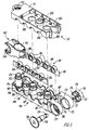
- Fig. 3 shows the building element of figs. 1 and 2 separated in its individual components.
- the bushing 122 (see fig. 1) has two coaxially positioned bushing tubes, the inner one of which having interior threads 171, the outer one having an annular locking groove 170 which terminates in a conical collar 175.
- the locking bosses 124 of the bushing are contiguous with the bushing at the root of the bosses so that these extend freely resiliently outwards in a radial direction.
- one of the fork arms of the element is provided with a hole to receive the bushing, said hole being formed with a guide 173 in the radial direction of the bushing so that these guides 173 can be received in grooves (not shown) in the bushing 122.
- the bushing is fixed hereby during the subsequent use.
- a locking ring 174 which is adapted to cooperate with the locking groove 170 upon mounting of the bushing 122.
- the locking groove 174 is formed with a conical guide face so that the bushing 122 can be correctly positioned using a relatively small force in the mounting of the bushing, while it is not possible in practice to remove the bushing 122 without destroying the parts.
- an even very strong mutual engagement is provided since the locking ring 174 and the conical collar 175 serve as barbs.
- the screw 130 has a head 176 from which a shank extends.
- the shank is formed with a bead 178 which is asymmetric so that it has a guide face and a stop face.
- the stop face is formed by a stepwise increase in the diameter of the shank, while the guide face is conical.
- the shank end facing away from the screw head 176 is provided with threads 179.
- the other fork arm of the element is provided with a hole having an interior cylinder face 177 which terminates at the end in a ring-shaped disc at a circular opening 180.
- the screw 130 When the screw is to be mounted, the threaded end is inserted through the hole 180, and then the bead 178 is caused to pass the opening 180, which can be done because of the guide face of the bead, while the stop face prevents withdrawal of the screw 130.
- the screw When the screw has been mounted in the hole of the fork arm, it can be moved longitudinally between two extreme positions. In one extreme position the bead 178 engages the area around the hole 180, where the screw head 176 in this position is approximately flush with the outer side of the fork arm. In the other extreme position the screw head 176 has been moved right down to the bottom of the hole 177 and engages the disc-shaped part. This travel is provided by screwing the screw into and out of the bushing 10, respectively.
- the screw 130 can advantageously be so short that it does not protrude beyond the contour of the element at any time.
- Fig. 3 moreover shows that the element 100 comprises two uniform threaded beams 181, each of which comprises a plurality of bushings 183 (here four) with interior threads 152, the bushings 183 being integral with a carrier beam 182 with a plurality of guide grooves 189.
- the bushings 183 form the threaded holes 150 shown in figs. 1 and 2, the bushings being therefore formed with a conical section 154 having two diametrically positioned locking bosses 155.
- the carrier beam 182 is tapered along its edges to facilitate mounting in the retaining grooves 185 provided in the upper part 190 (in the position shown in fig. 1) of the element.
- the lower part 191 has correponding retaining grooves, which, however, do not appear from the drawing.
- the edges on the upper part 190 and the lower part 191, respectively, are rounded so that the edges are caused to engage the bushings 183 quite tightly, which are thus caused to be flush with the side faces of the element 100.
- Some of the threaded holes 160 mentioned in connection with fig. 1 are provided by bushings 186, which have interior threads, and which are integral with the upper part 190.
- Others of the holes 160 are provided by a through-going cylinder tube 118, which likewise has interior threads and are integral with the upper part 190, but are moverover formed with a locking bead 187 which can be received in a complementary opening 188 on the lower part 191.
- the locking bead 187 has a guide face facilitating mounting, and a stop face preventing subsequent separation of the upper part 190 and the lower part 191. It will be seen that the shown element has two through-going cylinder tubes 118 as well as an additional cylinder tube 120.
- the cylinder tube 120 likewise has a locking ring at the end by which it can be locked to a hole 192 in the lower part 190, the hole 192 having a recessed locking bead and being adapted to receive the end of the cylinder tube 120, so that the locking bead provided on the cylinder tybe 120 is received in the hole 192 and is retained.
- Coupling between the upper part 190 and the lower part 191 via the three cylinder tubes 118, 120 provides a very safe and strong locking of the element 100.
- This locking is additionally intensified by the provision of two grooves 168 in the upper part 191 which are adapted to be received in the two guides 169 in the upper part 190.
- the groove 168 and the guide 169 moreover provide for reinforcement of the fork arms 126 and 128.
- the lower part 191 is provided with a plurality of holes along the edges to receive the bushings 183. This also appears from fig. 2.
- the coupling head 140 has a ring-shaped holding part 195 with an oval channel extending therethrough.
- This oval channel is provided with a front wall and a rear wall having the same radius of curvature, but the centers of the two radii of curvature are offset so that the channel is oval.
- a plurality of guides 194 are provided at the foot of the cylinder tube 120, which are adapted to engage the inner side of the ring-shaped holding part such that these in practice define the movements of the coupling head 140.
- Corresponding guides may be provided along the entire length of the cylinder tube 120 up to directly below the locking bead 193.
- the coupling head 140 is provided with locking pins 196 which are adapted to cooperate with a guide rail 198 provided behind the cylinder tube 120, it being possible to move the locking pins within the circle portion defined by the guide rail 198 with the locking grooves 197.
- a guide 199 is provided in the center of the guide rail 198.
- Corresponding guide grooves are of course also provided on the lower part 191 of the element.
- the coupling head can freely rotate between two extreme positions, the locking pins 194 being movable between the locking grooves 197.
- the locking pins 196 are received in the guides 199, whereby it is retained in a stable position. This is expedient in particular when the element is to be coupled with another element via the coupling head 140.
- FIGs. 4 and 5 show a fourth type of building element for a toy building set according to the invention.
- This building element is generally designated by the reference numeral 200, and it will be seen that the building element 200 has a box-shaped main body with a square cross-section.
- Figs. 6 and 7 show another embodiment of the fourth type of building element for a toy building set according to the invention, where this building element is generally designated by the reference numeral 300.
- the building element 200 has coupling studs 202 by means of which it can be interconnected with other parts incorporated in the toy building set.
- the building element 200 will also be provided with complementary coupling means on the underside, corresponding to those shown in fig. 6, by means of which it may e.g. be interconnected with the coupling studs 102 of the building element 100 shown in fig. 1.
- this interconnection will be purely frictional, and the building element 200 is therefore also provided with a screw 280 by means of which the frictional interconnection can be reinforced.
- the screw 280 will be provided with an annular bead so that the screw 280 can be moved in its axial direction between two extreme positions, where in one extreme position it is positioned entirely within the contours of the building element 200, and in the other extreme position it is positioned as shown in fig. 5. It will thus be possible to arrange the element 200 on elements without threaded holes as well as on elements with threaded holes 160 (fig. 1).
- the building element 200 is fixed with respect to the building element shown in fig. 1 by being caused to engage the coupling studs 102 releaseably and frictionally, following which the screw 280 is tightened with a tool provided for the purpose.
- This tool may e.g. have the shape of a screwdriver with a triangular end profile corresponding to the screw 130 shown in fig. 1. The tool will not be described in further detail.
- the building element will e.g. have a recess in connection with the second type of coupling means, so that the rear wall 261 of the threaded hole 260 corresponds to the outer wall of the element.
- the flexibility of the fork arms 226 and 228 will hereby be increased.
- the first coupling part in the second coupling means will be positioned on two form arms 226 and 228.
- a bushing 222 corresponding to the bushing 122 is non-releaseably arranged in a complementary hole in the fork arm 226, while a screw 230 corresponding to the screw 130 is arranged in an opening in the form arm 228, likewise non-releaseably.
- the function of this coupling part corresponds to the function of the coupling part shown in fig. 1.
- the axis of rotation defined by the coupling part shown in figs. 4 and 5 will be positioned at a distance a2 from the center of the coupling studs 202, the distance a2 being measured in parallel with the surface of the element 200 and corresponding to one and a half modular distances M.
- Figs. 6 and 7 shows the building element 300 which may be considered as being complementary to the building element 200 shown in figs. 4 and 5, since it is provided with a coupling head 340 for coupling with the second coupling type coupling part of the building element 200.
- the coupling head 340 has a wedge-shaped cut 346 and a partially circular coupling area 342 with a plurality of depressions 344.
- the coupling head 340 is positioned on a coupling arm extending obliquely upwardly from one side of the element 300.
- the coupling arm is provided with a stop 332 which, when the element 300 is interconnected with a second element via the coupling head 340, limits the rotatable movement provided hereby.
- the element 300 has complementary coupling means in the bottom, said coupling means being formed by projections 306 and a centrally arranged cylinder tube 382.
- the coupling studs of a second element can thus be received frictionally between the projections 306 and the cylinder tube 382.
- the cylinder tube 382 can advantageously have a length such that, when the element 300 is interconnected with a second element, it just touches the surface of this second element, so that no tensions will arise when the screw 380 of the element 300 is tightened.
- the function of the screw 380 corresponds to the function of the screw 280.
- the axis of rotation of the coupling head 340 will be positioned at a distance a3 from the center of the coupling stud 302, and this distance a3 corresponds to one and a half times the modular distance M of the coupling studs 302.
- the axis of rotation will likewise be positioned at a distance b3 from the upper side of the element 300, the distance b3 corresponding to the height of the coupling stud 302 added to half the height of the box-shaped body of the element 300.
- the building element 300 has so far been described as being an element with an obliquely upwardly protruding coupling arm, but a skilled person will appreciate that in another embodiment it may have an obliquely downwardly protruding coupling arm.
- the element may then have four coupling studs on the upper side, while on the underside it may be adapted to receive two coupling studs. The same observation may be made with respect to the building element 400 shown in figs. 8 and 9.
- Figs. 8 and 9 show another embodiment of the third type of building element according to the invention, said building element being generally designated by the reference numeral 400.
- the building element 400 comprises a rectangular body with coupling studs 402 on the upper side.
- the building element 400 has no coupling means complementary with the coupling studs 402, but has a coupling head 440 instead which is integral with the underside of the element.
- a threaded hole 460 with interior threads and a conical termination 464 with two locking bosses 465 is provided in the intersection point of the diagonals for the square formed by the coupling studs 402, a threaded hole 460 with interior threads and a conical termination 464 with two locking bosses 465 is provided.
- each of the side faces the building element 400 has respective threaded holes 450 with interior threads 452, the holes being terminated with a conical section 454 with two diametrically positioned locking bosses 455.
- these threaded holes 450 are provided with loose inserts which are mounted prior to the assembly of the element.
- the upper and lower halves of the element can be snapped together, the threaded hole 460 continuing in a cylinder tube which is downwardly terminated with snap means which can be caused to non-releaseably engage complementary snap means on the lower part of the element.
- these features are not shown in the drawing, but a skilled person will be able to understand the principle on the basis of fig. 3.
- the cylinder tube extending from the threaded hole 460, may be through-going so that it terminates in the wedge-shaped cut 446 of the coupling head 440. It will hereby be possible for the element 400 to receive a threaded shaft so that said shaft extends from the upper side as well as the underside of the element 400.
- the coupling head 440 has a coupling area 442 which is provided with a plurality of depressions 444.
- the toy building set of the invention can be supplemented with a building element complementary to the building element 400 shown in figs. 8 and 9, the coupling head 440 on the underside of the element being replaced by the first half of a second type of coupling means which consists of protruding fork arms.
- This first half like the coupling head 440, may be positioned such as to extend perpendicularly from the underside of the element.
- the second type of coupling means may extend perpendicularly from the upper side of the building element, while the underside of the element is then constructed as shown in fig. 6.
- the axis of rotation formed with the coupling head 440 will be positioned at a distance b4 from the lower edge of the building element corresponding to half the height of the box-shaped body of the building element.
- the element 400 can hereby be interconnected with the element 100 so that it can be incorporated in a structure with traditional building elements where their modular measures are maintained.
- Figs. 10 and 11 show a preferred embodiment of a second type of building element for use in the toy building set of the invention.
- This building element is not provided with coupling studs or coupling means complementary with these, but just comprises coupling means of a second type.
- the element is generally designated by the reference numeral 500 and it has a coupling head 540 at one end, said coupling head corresponding to the through-going coupling head shown in fig. 1 and having a wedge-shaped cut 546 and a coupling area 542 with depressions 544.
- the building element 500 has a coupling part complementary to the coupling head 540, said coupling part comprising a bushing 522 which is secured in one fork arm of the building element, while a screw 560 is journalled in the other fork arm.
- the coupling part complementary to the coupling head is formed by the inwardly directed face of the bushing 522 and the disc-shaped face 529.
- the element has a second coupling part which is complementary with the coupling head 540 and is arranged centrally in the building element 500. Flexibility is provided to the coupling part in that the coupling part is arranged centrally on two bridge sections having a relatively long free span.
- this coupling part will be somewhat smaller than that of the coupling part arranged on the fork arms, but it will be fully sufficient for achieving the desired function.
- the coupling head 540 is arranged on an arm forming an angle with the rest of the building element 500.
- the axis of rotation defined by the coupling head 540 will therefore be positioned at a distance b5, corresponding to half the height of the elements 100, 200, 300 and 400 without coupling studs, as well as to half the thickness of the element 500.
- the distance from the axis of rotation defined with the coupling head 540 and the axes of rotation defined with the screws 530 will hereby correspond to precisely the height of one of the mentioned elements.
- Fig. 12 shows a structure built with elements of the type which are described above.
- An element 1 forms the base of the structure, and it will be seen that this element substantially corresponds to the element 100 shown in figs. 1-3, but the element 1 is longer however, having eight pairs of coupling studs (101, fig. 1). It will moreover be seen that some of the threaded holes (150, fig. 1) are omitted. Nevertheless, the threaded holes maintain the modular distance m, the distance between two threaded holes in this embodiment being either one time or two times the modular distance m.
- a building element 2 corresponding to the building element 400 shown in figs. 8 and 9 is coupled via its coupling head (440, fig. 9) with the building element 1 via the coupling means which are provided thereon and are complementary to the coupling head on the element 2.
- a building element 3, corresponding to the building element 200 shown in figs. 4 and 5, is secured on the building element 1 at the side of the building element 2. This attachment is established by frictional coupling between the coupling studs (102, fig. 1) of the building element 1 and the corresponding complementary coupling means at the bottom of the element 3.
- This element 3 is moreover coupled with an element 4 via the second type of coupling means.
- the element 4 is simultaneously coupled to the base element 1 by friction, said coupling being established by means of frictional coupling between the coupling studs on the element 1 and the complementary coupling means in the bottom of the element 4.
- the coupling established by the second type of coupling means permits coupling of the elements 2 and 3 with a base plate - here the element 1 - in a manner such that the modular measures of the toy building set are observed.
- the elements 3 and 4 are coupled via the coupling means of the second type to provide a gap between the elements corresponding to precisely a modular measure.
- a building element 8 which is box-shaped and just has building studs on the upper side and complementary coupling means on the underside, can be coupled with the coupling studs (402, fig. 8; 202, fig. 4) on the elements 2 and 3, which takes place frictionally, as described above.
- a building element corresponding to the element 300 shown in figs. 6 and 7 is provided on the element 8.
- a building element 9 which corresponds to the element 8 and is coupled with an element 6 corresponding to the building element 200 shown in figs. 4 and 5, the element 9 being coupled with the elements 1 and 6 via frictional coupling.
- the structure shown in fig. 12 comprises an additional element 7 corresponding to the element 500 shown in figs. 10 and 11.
- this element just comprises coupling means of the second type and receives and retains at its one end the coupling head on the building element 5.
- the coupling head of the building element 7 is received and retained in corresponding manner by the coupling means of the building element 6 which are complementary to the coupling head.
- the body of the building element 7 extends in parallel with the body of the building element 1.
- the second type of coupling means have been explained above in connection with a relatively stiff coupling head, the snap coupling having been provided by flexible fork arms. However, nothing prevents the fork arms from being made more stiff, while the coupling head is made more flexible. This may be done e.g. by cutting through the coupling head longitudinally so that the coupling areas (142, fig. 1) can be moved toward each other in a flexible movement. When coupling has been established, the flexible movement may be fixed by placing a wedge in the cut. Thus, the invention is not restricted to the shown embodiment alone. Actually, also conceivable is an embodiment where the coupling head (140 in fig. 1) is adapted to grip a shaft part between the fork arms of a second element.
- Coupling of this type can also be established by snap effect.
- the shown embodiments have been explained in connection with the modular measure of the toy building set, but nothing prevents the elements of the invention from being embodied without modular measures. This, however, will reduce the usefulnes of the overall concept.
- the axis of rotation of the second type of coupling means may be positioned at other distances from the individual elements, it being also possible at other distances to maintain the mutual modular measure of the elements.
- the tertiary elements 100, 200, 300 and 400 as compact as possible, i.e. make the arm on which the coupling head is mounted as short as possible and make the fork arms as short as possible.
- the flexible and movable structures are then provided with the secondary building elemens corresponding to the building element 500.
- Fig. 13 shows a structure built with a toy building set according to the invention.
- An element 22, which corresponds to the element 1 shown in fig. 12, is provided with four wheels 21, which are screwed into threaded holes (150 in fig. 1) formed along the sides of the element 22.
- the coupling part, formed with the fork arms, at one end of the element 22 receives a coupling head on a tiltable platform 23. This reception takes place as described above.
- the tiltable platform 23 can be tilted from a position in which the lower part engages the surface of the element 22, to a position in which the contents of the platform 23 are discharged.
- Three more elements are secured to the element 22 by means of frictional coupling.
- One of these elements 24 is an element known per se, which is box-shaped and has coupling studs on the upper side and complementary coupling means in the bottom.
- a second element 25 corresponds to the element 200 shown in figs. 4 and 5, it having fork arms extending obliquely upwardly and being adapted to receive a coupling head on a second element.
- These two elements 24 and 25 in combination with the element 22 form a base for the third one of the elements - viz. the element 26 which serves as a cab, said element being actually just an element corresponding to the element 24 with a super-structure in the form of the cab.
- the element 26 can advantageously be provided with a screw corresponding to the screws 230 and 330 shown in figs.
- the coupling part on the element 25 receives a coupling head on a second element 27, which essentially corresponds to the element 500 shown in figs. 8 and 9, but is shorter however.
- the element 27 has a coupling head at its one end and a complementary coupling part at its other end.
- the second coupling part on the element 27 is adapted to receive a coupling head on a second element 28, which has the same length as the element 27, but has coupling heads at both ends.
- An element 29 receives the second one of the coupling heads on the element 28, said element having the same length as the elements 27 and 28. However, this element 29 has no coupling heads, but on the other hand two complementary coupling parts.
- the second coupling part on the element 29 receives a coupling head on a building element 30 having the shape of a bucket on an excavator.
- the elements 27, 28 and 29 constitute a movable connection by which a child during its play with a toy building set can perform digging movements with the bucket 30. It is clear that the elements 28 and 29 can be replaced by two elements corresponding to the element 27.
Landscapes
- Toys (AREA)
Abstract
Description
- The invention concerns a toy building set comprising a plurality of interconnectible building elements of the type defined in the introductory portion of claim 1.
- A plurality of toy building sets are known, consisting of box-shaped building elements with coupling studs on the upper side and complementary coupling means on the underside. Toy building sets of this type have been marketed for a number of years under the trademark DUPLO and are described in US-A-3 597 875. With building elements of this type it is possible to build compact and relatively simple structures, and these building elements therefore appeal to small children in particular.
- As the children develop, they try to meet their needs with toy building sets making it possible to build more complex structures. A plurality of examples of toy building sets of this type are known, an example being the toy building set described in the European Patent Application EP-A-460 081 This toy building set consists of a plurality of elements which can be fixed mutually in a variable angle. A toy building set of this type will be suitable for building large and flexible structures which contain moving parts.
- The object of the invention is to provide a toy building set which consists of a plurality of interconnectible building elements, making it possible to combine the advantages possessed by the box-shaped building elements having coupling studs with the flexibility possessed by the toy building set with rotatably interconnectible building elements.
- This object is achieved in that the toy building set additionally comprises a third type of building element and a fourth type of building element as stated in the characterizing portion of claim 1.
- The invention provides various embodiments of the third and fourth types of building element, and these are described in the subclaims.
- The invention is unique in the shown embodiments in that the modular measures known from the first type of building elements are maintained in the interconnection in certain positions with the elements of the second and the third types. This applies both to the interconnection of the elements in elongation of each other and to the building of structures in the stacking direction.
- The invention provides a toy building set by means of which it is possible to construct both small, compact and large, flexible structures.
- A building element of the third type is unique in that the coupling parts of the second set of coupling means are adapted for mutual interconnection by elastic movement of at least one coupling part, a locking device being provided for mutual fixing of the coupling parts by blocking of said elastic movement so that two coupled elements are rotatably inter-connected. Thus, this element may be incorporated as a connection element between compact, box-shaped building elements with coupling studs and complementary coupling means - known under the trademark DUPLO - and more markedly constructional building elements for building more complex structures. The building element defined in the claim may expediently be provided with wheels such that it serves as a vehicle bottom for building vehicles and the like.
- The invention will be explained more fully below in connection with preferred embodiments and with reference to the drawing, in which
- fig. 1 is a perspective view of a preferred embodiment of a third type of building element used in the invention,
- fig. 2 is a bottom view of the building element shown in fig. 1,
- fig. 3 is an exploded view of the components incorporated in the building element shown in fig. 1,
- fig. 4 is a perspective view of a preferred embodiment of a fourth type of building element used in the invention,
- fig. 5 is a side view of the building element shown in fig. 4,
- fig. 6 is a perspective view of a preferred embodiment of the fourth type of building element used in the invention,
- fig. 7 is a side view of the building element shown in fig. 6,
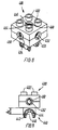
- fig. 8 shows a preferred embodiment of a third type of building element used in the invention,
- fig. 9 is a side view of the building element shown in fig. 8,
- fig. 10 is a perspective view of an embodiment of the second type of a building element for use in a toy building set according to the invention,
- fig. 11 is a side view of the building element shown in fig. 10,
- fig. 12 shows a structure built with building elements from a toy building set according to the invention, and
- fig. 13 shows another structure built with building elements from a toy building set according to the invention.
-
- Figs. 1 and 2 show a preferred embodiment of a third type of building element for a toy building set according to the invention. The building element is generally designated by the
reference numeral 100 and consists of a box-shaped body which hascoupling studs 102 on the upper side in its preferred embodiment. Both the shape and the position of thecoupling studs 102 are known per se, thecoupling studs 102 being arranged in rows with a mutual modular distance M. Fig. 2 is a bottom view of thebuilding element 100 and shows that thebottom 104 of thebuilding element 100 is recessed with respect to therim 110,rear end 112 andfront end 114 of the building element. A plurality ofprojections 106 are provided interiorly along theedge 110, which, together with a number of cylinder tubes 108 - here one - form complementary coupling means for receiving thecoupling studs 102 of another element. Thecoupling studs 102 are received between thecylinder tube 108 and theprojections 106 in a releaseable friction coupling in a manner known per se. In addition to thecylinder tube 108, twocylindrical projections 118 are shown, which are not necessarily included in the complementary coupling means because they serve a different purpose and merely constitute the termination of a cylinder tube extending therethrough. The same applies to acylinder tube 120 in thefront end 114 of thebuilding element 100, since the through-goingcylinder tubes building element 100 upon assembly of this, which will be explained in connection with fig. 3. - Fig. 1 shows a
bushing 122 which is received non-release-ably in onefork arm 126 of the building element in the manufacture of said element. Thebushing 122 has interior threads for ascrew 130 which is received in theother fork arm 128 of the building element, likewise non-releaseably. Thebushing 122 has a plurality oflocking bosses 124 which are flexible in the axial direction of thescrew 130. Together with a disc-shaped region 129 on thefork arm 128 the bushing 122 constitutes part of a coupling part in a second type of coupling means. - A
coupling head 140, constituting the second coupling part of the second type of coupling means, is provided at the other end of the building element. This second coupling part has acircular coupling area 142 on each side of thecoupling head 140. Thiscoupling area 142 is open at one side, thecoupling head 140 having a substantially wedge-shaped cut 146. Thecoupling head 140 is adapted to be received between thefork arms circular coupling areas 142 of the coupling head being caused to contact corresponding coupling areas of the first coupling part in the form of thebushing 122 and thecircular face 129. It will be seen that thecircular engagement faces 142 are provided with a plurality ofdepressions 144 in which thelocking flaps 124 of thebushing 122 can be retained. Two building elements are interconnected in that thecoupling head 140 is received between thefork arms fork arms screw 130, whereby the two elements form a rotatable connection about the direction defined by the longitudinal axis of the screw. The rotatable movement between two building elements is limited by astop 132, thereby eliminating the risk of a child getting its fingers squeezed between the two inter-connected building elements. Between the rotatable connection and the centre of the closest coupling stud there will be a distance a1, which is preferably a whole multiple of half the modular distance M. The distance a1 is here one and a half times M for both ends. - In a preferred embodiment the
coupling head 140 is rotatably journalled in the front end of thebuilding element 100, with thecylinder tube 120 serving as an axis of rotation for this rotatable movement. This will be explained in connection with fig. 3. - A plurality of
holes 150 withinterior threads 152 are provided along the sides of thebuilding element 100. Theholes 150 being adapted to receive the threaded section of a screw on a second building element incorporated in the toy building set. This building element may e.g. be a wheel so that the screw serves as a hub. As will be seen, the threadedhole 150 terminates in aconical section 154 which serves as a relief or transitional area for a corresponding conical section on the screw (not shown). Theconical section 154 is moreover provided with twolocking bosses 155 provided diametrically in the hole and adapted to engage corresponding, complementary recesses on the screw. - The upper side of the building element is formed with threaded
holes 160 between the coupling studs arranged at a mutual modular distance, and these threadedholes 160, like the threadedholes 150 on the sides of the building element, haveinterior threads 162 and aconical section 164 with two diametrically providedlocking bosses 165. The threadedholes 160 are provided in the intersection point of the diagonals for a square formed by fouradjacent coupling studs 102. This means that the threadedholes 160 follow the same mutual modular distance M as thecoupling studs 102. The same applies to the threadedholes 150, since they are disposed opposite the threadedholes 160 and thereby centrally between thecoupling studs 102 in the shown embodiment. In the shown embodiment, the building element has fivecoupling studs 102 arranged in pairs and thereby four threadedholes 160. There will thus also be four threadedholes 150 on each side of the building element. Thebuilding element 100 may e.g. serve as a vehicle bottom, and if the length of thebuilding element 100 is increased, it may be expedient to omit individual pairs ofwheels 150, because it is not possible to attach wheels in two adjacent holes anyhow. - Fig. 3 shows the building element of figs. 1 and 2 separated in its individual components. It will be seen that the bushing 122 (see fig. 1) has two coaxially positioned bushing tubes, the inner one of which having
interior threads 171, the outer one having anannular locking groove 170 which terminates in aconical collar 175. It will moreover be seen that the lockingbosses 124 of the bushing are contiguous with the bushing at the root of the bosses so that these extend freely resiliently outwards in a radial direction. It will be seen that one of the fork arms of the element is provided with a hole to receive the bushing, said hole being formed with aguide 173 in the radial direction of the bushing so that theseguides 173 can be received in grooves (not shown) in thebushing 122. The bushing is fixed hereby during the subsequent use. At the end of the opening of the fork arm there is moreover provided alocking ring 174 which is adapted to cooperate with the lockinggroove 170 upon mounting of thebushing 122. Like thecollar 175, the lockinggroove 174 is formed with a conical guide face so that thebushing 122 can be correctly positioned using a relatively small force in the mounting of the bushing, while it is not possible in practice to remove thebushing 122 without destroying the parts. Thus, an even very strong mutual engagement is provided since thelocking ring 174 and theconical collar 175 serve as barbs. - The
screw 130 has ahead 176 from which a shank extends. The shank is formed with abead 178 which is asymmetric so that it has a guide face and a stop face. The stop face is formed by a stepwise increase in the diameter of the shank, while the guide face is conical. The shank end facing away from thescrew head 176 is provided withthreads 179. The other fork arm of the element is provided with a hole having aninterior cylinder face 177 which terminates at the end in a ring-shaped disc at acircular opening 180. When the screw is to be mounted, the threaded end is inserted through thehole 180, and then thebead 178 is caused to pass theopening 180, which can be done because of the guide face of the bead, while the stop face prevents withdrawal of thescrew 130. When the screw has been mounted in the hole of the fork arm, it can be moved longitudinally between two extreme positions. In one extreme position thebead 178 engages the area around thehole 180, where thescrew head 176 in this position is approximately flush with the outer side of the fork arm. In the other extreme position thescrew head 176 has been moved right down to the bottom of thehole 177 and engages the disc-shaped part. This travel is provided by screwing the screw into and out of the bushing 10, respectively. Thescrew 130 can advantageously be so short that it does not protrude beyond the contour of the element at any time. - Fig. 3 moreover shows that the
element 100 comprises two uniform threadedbeams 181, each of which comprises a plurality of bushings 183 (here four) withinterior threads 152, thebushings 183 being integral with acarrier beam 182 with a plurality ofguide grooves 189. Thebushings 183 form the threadedholes 150 shown in figs. 1 and 2, the bushings being therefore formed with aconical section 154 having two diametrically positioned lockingbosses 155. It will be seen that thecarrier beam 182 is tapered along its edges to facilitate mounting in the retaininggrooves 185 provided in the upper part 190 (in the position shown in fig. 1) of the element. The lower part 191 has correponding retaining grooves, which, however, do not appear from the drawing. The edges on theupper part 190 and the lower part 191, respectively, are rounded so that the edges are caused to engage thebushings 183 quite tightly, which are thus caused to be flush with the side faces of theelement 100. Some of the threadedholes 160 mentioned in connection with fig. 1 are provided bybushings 186, which have interior threads, and which are integral with theupper part 190. Others of theholes 160 are provided by a through-goingcylinder tube 118, which likewise has interior threads and are integral with theupper part 190, but are moverover formed with a lockingbead 187 which can be received in acomplementary opening 188 on the lower part 191. The lockingbead 187 has a guide face facilitating mounting, and a stop face preventing subsequent separation of theupper part 190 and the lower part 191. It will be seen that the shown element has two through-goingcylinder tubes 118 as well as anadditional cylinder tube 120. Thecylinder tube 120 likewise has a locking ring at the end by which it can be locked to ahole 192 in thelower part 190, thehole 192 having a recessed locking bead and being adapted to receive the end of thecylinder tube 120, so that the locking bead provided on thecylinder tybe 120 is received in thehole 192 and is retained. Coupling between theupper part 190 and the lower part 191 via the threecylinder tubes element 100. This locking is additionally intensified by the provision of twogrooves 168 in the upper part 191 which are adapted to be received in the twoguides 169 in theupper part 190. Thegroove 168 and theguide 169 moreover provide for reinforcement of thefork arms bushings 183. This also appears from fig. 2. - The
coupling head 140 has a ring-shaped holdingpart 195 with an oval channel extending therethrough. This oval channel is provided with a front wall and a rear wall having the same radius of curvature, but the centers of the two radii of curvature are offset so that the channel is oval. A plurality of guides 194 (here four) are provided at the foot of thecylinder tube 120, which are adapted to engage the inner side of the ring-shaped holding part such that these in practice define the movements of thecoupling head 140. Corresponding guides may be provided along the entire length of thecylinder tube 120 up to directly below the lockingbead 193. It will moreover be seen that thecoupling head 140 is provided with lockingpins 196 which are adapted to cooperate with aguide rail 198 provided behind thecylinder tube 120, it being possible to move the locking pins within the circle portion defined by theguide rail 198 with the lockinggrooves 197. It will be seen that aguide 199 is provided in the center of theguide rail 198. Corresponding guide grooves are of course also provided on the lower part 191 of the element. When thelocking pin 196 is moved along theguide rail 198, the coupling head is pulled slightly forward, so that the rear wall of the ring-shaped holding part engages theguide 194 facing thebushing 186. In this position the coupling head can freely rotate between two extreme positions, the locking pins 194 being movable between the lockinggrooves 197. When thecoupling head 140 is directed straight forward and is moved rearwardly, the locking pins 196 are received in theguides 199, whereby it is retained in a stable position. This is expedient in particular when the element is to be coupled with another element via thecoupling head 140. - Figs. 4 and 5 show a fourth type of building element for a toy building set according to the invention. This building element is generally designated by the
reference numeral 200, and it will be seen that thebuilding element 200 has a box-shaped main body with a square cross-section. Figs. 6 and 7 show another embodiment of the fourth type of building element for a toy building set according to the invention, where this building element is generally designated by thereference numeral 300. - It will be seen that the
building element 200 hascoupling studs 202 by means of which it can be interconnected with other parts incorporated in the toy building set. In addition, thebuilding element 200 will also be provided with complementary coupling means on the underside, corresponding to those shown in fig. 6, by means of which it may e.g. be interconnected with thecoupling studs 102 of thebuilding element 100 shown in fig. 1. As explained before, this interconnection will be purely frictional, and thebuilding element 200 is therefore also provided with a screw 280 by means of which the frictional interconnection can be reinforced. The screw 280 will be provided with an annular bead so that the screw 280 can be moved in its axial direction between two extreme positions, where in one extreme position it is positioned entirely within the contours of thebuilding element 200, and in the other extreme position it is positioned as shown in fig. 5. It will thus be possible to arrange theelement 200 on elements without threaded holes as well as on elements with threaded holes 160 (fig. 1). - The
building element 200 is fixed with respect to the building element shown in fig. 1 by being caused to engage thecoupling studs 102 releaseably and frictionally, following which the screw 280 is tightened with a tool provided for the purpose. This tool may e.g. have the shape of a screwdriver with a triangular end profile corresponding to thescrew 130 shown in fig. 1. The tool will not be described in further detail. As shown in fig. 4, the building element will e.g. have a recess in connection with the second type of coupling means, so that therear wall 261 of the threadedhole 260 corresponds to the outer wall of the element. The flexibility of thefork arms form arms bushing 222 corresponding to thebushing 122 is non-releaseably arranged in a complementary hole in thefork arm 226, while ascrew 230 corresponding to thescrew 130 is arranged in an opening in theform arm 228, likewise non-releaseably. The function of this coupling part corresponds to the function of the coupling part shown in fig. 1. - The axis of rotation defined by the coupling part shown in figs. 4 and 5 will be positioned at a distance a2 from the center of the
coupling studs 202, the distance a2 being measured in parallel with the surface of theelement 200 and corresponding to one and a half modular distances M. - Figs. 6 and 7 shows the
building element 300 which may be considered as being complementary to thebuilding element 200 shown in figs. 4 and 5, since it is provided with a coupling head 340 for coupling with the second coupling type coupling part of thebuilding element 200. The coupling head 340 has a wedge-shapedcut 346 and a partiallycircular coupling area 342 with a plurality ofdepressions 344. The coupling head 340 is positioned on a coupling arm extending obliquely upwardly from one side of theelement 300. The coupling arm is provided with astop 332 which, when theelement 300 is interconnected with a second element via the coupling head 340, limits the rotatable movement provided hereby. With respect to thecoupling studs 302, theelement 300 has complementary coupling means in the bottom, said coupling means being formed byprojections 306 and a centrally arrangedcylinder tube 382. The coupling studs of a second element can thus be received frictionally between theprojections 306 and thecylinder tube 382. Thecylinder tube 382 can advantageously have a length such that, when theelement 300 is interconnected with a second element, it just touches the surface of this second element, so that no tensions will arise when thescrew 380 of theelement 300 is tightened. The function of thescrew 380 corresponds to the function of the screw 280. Here too, the axis of rotation of the coupling head 340 will be positioned at a distance a3 from the center of thecoupling stud 302, and this distance a3 corresponds to one and a half times the modular distance M of thecoupling studs 302. The axis of rotation will likewise be positioned at a distance b3 from the upper side of theelement 300, the distance b3 corresponding to the height of thecoupling stud 302 added to half the height of the box-shaped body of theelement 300. Thebuilding element 300 has so far been described as being an element with an obliquely upwardly protruding coupling arm, but a skilled person will appreciate that in another embodiment it may have an obliquely downwardly protruding coupling arm. The element may then have four coupling studs on the upper side, while on the underside it may be adapted to receive two coupling studs. The same observation may be made with respect to thebuilding element 400 shown in figs. 8 and 9. - Figs. 8 and 9 show another embodiment of the third type of building element according to the invention, said building element being generally designated by the
reference numeral 400. Thebuilding element 400 comprises a rectangular body withcoupling studs 402 on the upper side. Thebuilding element 400 has no coupling means complementary with thecoupling studs 402, but has acoupling head 440 instead which is integral with the underside of the element. In the intersection point of the diagonals for the square formed by thecoupling studs 402, a threadedhole 460 with interior threads and aconical termination 464 with two lockingbosses 465 is provided. Centrally in each of the side faces thebuilding element 400 has respective threadedholes 450 withinterior threads 452, the holes being terminated with aconical section 454 with two diametrically positioned lockingbosses 455. Like the element shown in figs. 1-3, these threadedholes 450 are provided with loose inserts which are mounted prior to the assembly of the element. The upper and lower halves of the element can be snapped together, the threadedhole 460 continuing in a cylinder tube which is downwardly terminated with snap means which can be caused to non-releaseably engage complementary snap means on the lower part of the element. However, these features are not shown in the drawing, but a skilled person will be able to understand the principle on the basis of fig. 3. The cylinder tube, extending from the threadedhole 460, may be through-going so that it terminates in the wedge-shapedcut 446 of thecoupling head 440. It will hereby be possible for theelement 400 to receive a threaded shaft so that said shaft extends from the upper side as well as the underside of theelement 400. Like the coupling head shown in fig. 1, thecoupling head 440 has acoupling area 442 which is provided with a plurality ofdepressions 444. - A skilled person will appreciate that the toy building set of the invention can be supplemented with a building element complementary to the
building element 400 shown in figs. 8 and 9, thecoupling head 440 on the underside of the element being replaced by the first half of a second type of coupling means which consists of protruding fork arms. This first half, like thecoupling head 440, may be positioned such as to extend perpendicularly from the underside of the element. Alternatively, the second type of coupling means may extend perpendicularly from the upper side of the building element, while the underside of the element is then constructed as shown in fig. 6. - In the preferred embodiment, the axis of rotation formed with the
coupling head 440 will be positioned at a distance b4 from the lower edge of the building element corresponding to half the height of the box-shaped body of the building element. Theelement 400 can hereby be interconnected with theelement 100 so that it can be incorporated in a structure with traditional building elements where their modular measures are maintained. - Figs. 10 and 11 show a preferred embodiment of a second type of building element for use in the toy building set of the invention. This building element is not provided with coupling studs or coupling means complementary with these, but just comprises coupling means of a second type. As will be seen from the figure, the element is generally designated by the
reference numeral 500 and it has acoupling head 540 at one end, said coupling head corresponding to the through-going coupling head shown in fig. 1 and having a wedge-shapedcut 546 and acoupling area 542 withdepressions 544. At its other end thebuilding element 500 has a coupling part complementary to thecoupling head 540, said coupling part comprising abushing 522 which is secured in one fork arm of the building element, while a screw 560 is journalled in the other fork arm. The coupling part complementary to the coupling head is formed by the inwardly directed face of thebushing 522 and the disc-shapedface 529. In addition, the element has a second coupling part which is complementary with thecoupling head 540 and is arranged centrally in thebuilding element 500. Flexibility is provided to the coupling part in that the coupling part is arranged centrally on two bridge sections having a relatively long free span. The flexibility of this coupling part will be somewhat smaller than that of the coupling part arranged on the fork arms, but it will be fully sufficient for achieving the desired function. As will be seen from the figures, thecoupling head 540 is arranged on an arm forming an angle with the rest of thebuilding element 500. The axis of rotation defined by thecoupling head 540 will therefore be positioned at a distance b5, corresponding to half the height of theelements element 500. The distance from the axis of rotation defined with thecoupling head 540 and the axes of rotation defined with thescrews 530 will hereby correspond to precisely the height of one of the mentioned elements. - Fig. 12 shows a structure built with elements of the type which are described above. An element 1 forms the base of the structure, and it will be seen that this element substantially corresponds to the
element 100 shown in figs. 1-3, but the element 1 is longer however, having eight pairs of coupling studs (101, fig. 1). It will moreover be seen that some of the threaded holes (150, fig. 1) are omitted. Nevertheless, the threaded holes maintain the modular distance m, the distance between two threaded holes in this embodiment being either one time or two times the modular distance m. - A
building element 2 corresponding to thebuilding element 400 shown in figs. 8 and 9 is coupled via its coupling head (440, fig. 9) with the building element 1 via the coupling means which are provided thereon and are complementary to the coupling head on theelement 2. A building element 3, corresponding to thebuilding element 200 shown in figs. 4 and 5, is secured on the building element 1 at the side of thebuilding element 2. This attachment is established by frictional coupling between the coupling studs (102, fig. 1) of the building element 1 and the corresponding complementary coupling means at the bottom of the element 3. This element 3 is moreover coupled with anelement 4 via the second type of coupling means. Theelement 4 is simultaneously coupled to the base element 1 by friction, said coupling being established by means of frictional coupling between the coupling studs on the element 1 and the complementary coupling means in the bottom of theelement 4. It should be noted that the coupling established by the second type of coupling means permits coupling of theelements 2 and 3 with a base plate - here the element 1 - in a manner such that the modular measures of the toy building set are observed. It will be seen that theelements 3 and 4 are coupled via the coupling means of the second type to provide a gap between the elements corresponding to precisely a modular measure. It will moreover be seen that the upper sides of theelements 2 and 3 likewise observe the modular measures so that a building element 8, which is box-shaped and just has building studs on the upper side and complementary coupling means on the underside, can be coupled with the coupling studs (402, fig. 8; 202, fig. 4) on theelements 2 and 3, which takes place frictionally, as described above. A building element corresponding to theelement 300 shown in figs. 6 and 7 is provided on the element 8. - At the other end of the element 1 there is provided a building element 9, which corresponds to the element 8 and is coupled with an element 6 corresponding to the
building element 200 shown in figs. 4 and 5, the element 9 being coupled with the elements 1 and 6 via frictional coupling. As will be seen, the structure shown in fig. 12 comprises an additional element 7 corresponding to theelement 500 shown in figs. 10 and 11. As explained before, this element just comprises coupling means of the second type and receives and retains at its one end the coupling head on thebuilding element 5. The coupling head of the building element 7 is received and retained in corresponding manner by the coupling means of the building element 6 which are complementary to the coupling head. It will be seen that the body of the building element 7 extends in parallel with the body of the building element 1. It is clear of course that the screws in theelements 3 and 4 can be tightened to reinforce the frictional coupling with the element 1. Corresponding tightenings can be affected with the previously mentioned screws to counteract the flexibility of the fork arms. An extremely stable structure can be achieved hereby, the shown structure being just included to illustrate the modular measure of the building set. - The invention has been described above in connection with preferred embodiments, and a plurality of modifications of the shown structures can therefore be made. Thus, nothing prevents the coupling studs and the complementary coupling means from being positioned at other points than on the upper side and underside of the building elements. Strictly speaking it is not even necessary that these coupling means are arranged on two opposed sides, and actually they can be arranged on two adjoining sides. However, this will often be considered inexpedient since the play value of the toy building set is considered to be greatest precisely when it is possible to stack the individual elements.
- The second type of coupling means have been explained above in connection with a relatively stiff coupling head, the snap coupling having been provided by flexible fork arms. However, nothing prevents the fork arms from being made more stiff, while the coupling head is made more flexible. This may be done e.g. by cutting through the coupling head longitudinally so that the coupling areas (142, fig. 1) can be moved toward each other in a flexible movement. When coupling has been established, the flexible movement may be fixed by placing a wedge in the cut. Thus, the invention is not restricted to the shown embodiment alone. Actually, also conceivable is an embodiment where the coupling head (140 in fig. 1) is adapted to grip a shaft part between the fork arms of a second element. Coupling of this type can also be established by snap effect. The shown embodiments have been explained in connection with the modular measure of the toy building set, but nothing prevents the elements of the invention from being embodied without modular measures. This, however, will reduce the usefulnes of the overall concept. Correspondingly, the axis of rotation of the second type of coupling means may be positioned at other distances from the individual elements, it being also possible at other distances to maintain the mutual modular measure of the elements. However, at the present time it is preferred to make the
tertiary elements building element 500. - Fig. 13 shows a structure built with a toy building set according to the invention. An
element 22, which corresponds to the element 1 shown in fig. 12, is provided with fourwheels 21, which are screwed into threaded holes (150 in fig. 1) formed along the sides of theelement 22. The coupling part, formed with the fork arms, at one end of theelement 22 receives a coupling head on atiltable platform 23. This reception takes place as described above. Thetiltable platform 23 can be tilted from a position in which the lower part engages the surface of theelement 22, to a position in which the contents of theplatform 23 are discharged. Three more elements are secured to theelement 22 by means of frictional coupling. One of theseelements 24 is an element known per se, which is box-shaped and has coupling studs on the upper side and complementary coupling means in the bottom. Asecond element 25 corresponds to theelement 200 shown in figs. 4 and 5, it having fork arms extending obliquely upwardly and being adapted to receive a coupling head on a second element. These twoelements element 22 form a base for the third one of the elements - viz. theelement 26 which serves as a cab, said element being actually just an element corresponding to theelement 24 with a super-structure in the form of the cab. Theelement 26 can advantageously be provided with a screw corresponding to thescrews 230 and 330 shown in figs. 4-7, whereby the frictional attachment is reinforced. The coupling part on theelement 25 receives a coupling head on asecond element 27, which essentially corresponds to theelement 500 shown in figs. 8 and 9, but is shorter however. Theelement 27 has a coupling head at its one end and a complementary coupling part at its other end. The second coupling part on theelement 27 is adapted to receive a coupling head on asecond element 28, which has the same length as theelement 27, but has coupling heads at both ends. Anelement 29 receives the second one of the coupling heads on theelement 28, said element having the same length as theelements element 29 has no coupling heads, but on the other hand two complementary coupling parts. The second coupling part on theelement 29 receives a coupling head on abuilding element 30 having the shape of a bucket on an excavator. Theelements bucket 30. It is clear that theelements element 27.
Claims (20)
- A toy building set comprisingbox shaped toy building elements (8, 9) of a first type having a first type of coupling means (102, 202, 302, 402) including coupling studs on an outer surface thereof and recesses for receiving coupling studs on another toy building element of the first type so as to stack toy building elements of the first type in frictional interconnection,toy building elements (500) of a second type having an elongate body with a second type of coupling means (540; 522, 529, 530) allowing establishing a releasable pivotal interconnection of two toy building elements (500) of the second type, toy building elements (8, 9) of the first type not being directly interconnectable with toy building elements (500) of the second type,
characterized in that the toy building set further comprisestoy building elements (100, 400) of a third type having coupling means (102, 402) of the first type including said coupling studs (102) on an outer surface thereof allowing releasable frictional interconnection with the recesses on toy building elements (8, 9) of the first type, and having coupling means (140, 440) of the second type allowing pivotal interconnection with toy building elements (500) of the second type, and said elements (100, 400) of the third type being provided with a threaded hole (160, 460) for receiving a screw, andtoy building elements (200, 300) of a fourth type having recesses for receiving said coupling studs (102, 402) on a toy building element (100, 400) of the third type in releasable frictional interconnection, and having a threaded screw (380) receivable in said threaded hole. - A toy building set according to claim 1 characterized in that the screw (380) is slidably received in the building element (200, 300) of the fourth type, the screw being slidably movable in the direction of stacking defined by the first type of coupling means (102, 202, 302, 402) between a position in which it is positioned completely within the contour of the building element (200; 300) of the fourth type, and another position in which the threaded part of the screw extends beyond the contour of the building element (200; 300).
- A toy building set according to claim 2, wherein the coupling studs (102; 202; 302; 402) in the first type of coupling means are arranged in parallel rows with a mutual modular distance (M) between the coupling studs (102; 202; 302; 402), characterized in that the screw connection is provided in the intersection point of the diagonals for a square with four coupling studs (102; 202; 302; 402) in the corners.
- A toy building set according to claims 1-3, characterized in that the width of the building elements (100; 200; 300; 400; 500;) is a whole multiple of the modular distance (M) of the coupling studs (102; 202; 302; 402).
- A toy building set according to claim 4, characterized in that the width of the elements (100; 200; 300; 400; 500; 1-9) is twice the modular distance (M).
- A toy building set according to claims 1-5, characterized in that the height of the box-shaped body of the building elements (100; 200; 300; 400) of the first third and fourth type corresponds to the height of the box-shaped, first type of building element (8, 9) not including coupling studs.
- A toy building set according to claim 6, characterized in that the height of the second type of building element (500) corresponds to the height of the box-shaped body of the third or fourth type of building element (100; 200; 300; 400).
- A toy building set according to claim 1-7 characterized by an elongated building element (100) of the third type hving coupling studs (102) and recesses of the first type on opposed sides and mutually complementary first and second coupling parts (140; 122, 126, 128, 129, 130) of the second type of coupling means at opposed ends.
- A toy building set according to claim 8, characterized in that the first coupling part (140) is rotationally connected with the element (100) of the third type about an axis transversely to the axis of rotation formed by interconnection of the second type of coupling means.
- A toy building set according to claim 8 or 9, characterized in that the element (100) of the third type has a row of threaded holes (150) along two long sides, and that the distance between the threaded holes (150) corresponds to the modular distance (M) of the coupling studs (102).
- A toy building set according to claims 8-10, characterized in that the distance in the longitudinal direction of the element (100) of the third type between the center of any of the coupling studs (102) and the axis of rotation formed with the second type of coupling means (122, 126, 128, 129, 130, 140) is a whole multiple of half the modular distance (M) of the coupling studs (102).
- A toy building set according to claim 11, characterized in that the distance between the axis of rotation and the adjacent pair of coupling studs (102) corresponds to three times half the modular distance (M).
- A toy building set according to claim 1-7 characterized by a box shaped building element (200; 300) of the fourth type having coupling studs (202; 302) and recesses (306, 382) of the first type on oppossed sides and a coupling part (222, 226, 228, 230; 342, 344, 346) of the second type extending obliquely from the contour of the box shaped element, such that the pivot axis of the coupling part is positioned outside the box shaped element proper.
- A toy building set according to claim 13, characterized in that the distance (a2; a3) in the longitudinal direction of the box shaped element (200; 300) between the center of any of the coupling studs (202; 302) and the axis of rotation formed with the second type of coupling means (222, 226, 228, 230; 342, 344, 346) is a multiple of half the modular distance (M) of the coupling studs (202; 302).
- A toy building set according to claim 14, characterized in that the distance (a2; a3) between the axis of rotation and the adjacent pair of coupling studs corresponds to twice half the modular distance (M).
- A toy building set according to claims 13-15, characterized in that the axis of rotation is positioned at a height (b2) above the upper side of the body corresponding to the height of the coupling studs (202; 203) added to a whole multiple of the height of the box shaped body.
- A toy building set according to claim 16, characterized in that the height (b2) corresponds to the height of the coupling studs (202; 302) added to half the height of the box shaped body.
- A toy building set according to claims 1-7, characterized by a box shaped building element (400) of the fourth type with coupling studs (402) on one side and one of the coupling parts (440) of the second type of coupling means on the opposed side.
- A toy building set according to claim 18, characterized in that the axis of rotation of the coupling part (440) is positioned below and centrally between two coupling studs (402).
- A toy building set according to claims 18-19, characterized in that the distance (b4) between the bottom of the box shaped building element (400) and the axis of rotation corresponds to half the height of the box shaped element.
Applications Claiming Priority (4)
| Application Number | Priority Date | Filing Date | Title |
|---|---|---|---|
| DK182891 | 1991-11-06 | ||
| DK1828/91 | 1991-11-06 | ||
| DK182891A DK172267B1 (en) | 1991-11-06 | 1991-11-06 | Toy building kits and building elements therefor |
| PCT/DK1992/000319 WO1993008886A1 (en) | 1991-11-06 | 1992-11-05 | A toy building set______________________________________________ |
Publications (2)
| Publication Number | Publication Date |
|---|---|
| EP0612262A1 EP0612262A1 (en) | 1994-08-31 |
| EP0612262B1 true EP0612262B1 (en) | 1999-03-10 |
Family
ID=8108353
Family Applications (1)
| Application Number | Title | Priority Date | Filing Date |
|---|---|---|---|
| EP92923707A Expired - Lifetime EP0612262B1 (en) | 1991-11-06 | 1992-11-05 | A toy building set |
Country Status (8)
| Country | Link |
|---|---|
| US (1) | US5645463A (en) |
| EP (1) | EP0612262B1 (en) |
| JP (1) | JP3621411B2 (en) |
| CN (1) | CN1049363C (en) |
| AU (1) | AU2941892A (en) |
| DE (1) | DE69228610T2 (en) |
| DK (2) | DK172267B1 (en) |
| WO (1) | WO1993008886A1 (en) |
Families Citing this family (75)
| Publication number | Priority date | Publication date | Assignee | Title |
|---|---|---|---|---|
| DK173099B1 (en) * | 1994-05-18 | 2000-01-17 | Lego As | Screw and nut with built-in torque limiting clutch |
| DK171783B1 (en) * | 1994-11-14 | 1997-05-26 | Lego As | Overload-proof building element for structural building kits |
| DK102095A (en) | 1995-09-14 | 1997-03-15 | Lego As | constructional |
| US5947787A (en) * | 1997-09-24 | 1999-09-07 | Parvia Corporation | Modular lattice substructure for a toy building set |
| US5924905A (en) * | 1997-09-24 | 1999-07-20 | Parvia Corporation | Modular terrain for a toy building set |
| US6129605A (en) * | 1997-09-24 | 2000-10-10 | Parvia Corporation | Modular base units for a toy building set |
| US5951356A (en) * | 1997-10-27 | 1999-09-14 | Parvia Corporation | Modular lattice substructure for a toy building set having columns and foundations |
| US5993283A (en) * | 1997-09-30 | 1999-11-30 | Parvia Corporation | Modular buildings for a toy building set |
| US6102770A (en) * | 1997-10-03 | 2000-08-15 | Parvia Corporation | Toy vehicular electromechanical guidance apparatus |
| US5865661A (en) * | 1997-10-03 | 1999-02-02 | Parvia Corporation | Toy vehicular drive apparatus |
| US6007401A (en) | 1997-10-03 | 1999-12-28 | Parvia Corporation | Optoelectric remote control apparatus for guiding toy vehicles |
| US6012957A (en) * | 1997-10-27 | 2000-01-11 | Parvia Corporation | Single beam optoelectric remote control apparatus for control of toys |
| USD410704S (en) | 1998-03-18 | 1999-06-08 | Interlego Ag | Toy building element |
| DE19825130B4 (en) * | 1998-06-05 | 2006-04-27 | Best-Lock Group Ltd., Kowloon | building block |
| TW393335B (en) * | 1998-10-14 | 2000-06-11 | Interlego Ag | A toy building set |
| USD410705S (en) | 1998-10-14 | 1999-06-08 | Interlego Ag | Toy building element |
| USD419616S (en) * | 1998-10-14 | 2000-01-25 | Interlego Ag | Toy building element |
| DK174710B1 (en) * | 1998-10-14 | 2003-09-29 | Lego As | A toy |
| DK174518B1 (en) | 1999-01-15 | 2003-05-05 | Lego As | A toy |
| US6033282A (en) * | 1999-02-04 | 2000-03-07 | Youth Toy Enterprise Co., Ltd. | Multipurpose built-up measuring device |
| EP1207950B1 (en) * | 1999-09-03 | 2004-11-24 | Dae Sung Toys Co. Ltd. | Moveable and sectional block toy |
| US6264522B1 (en) | 1999-12-07 | 2001-07-24 | Marilyn M. Dickson | Construction system |
| KR20000063717A (en) * | 2000-08-01 | 2000-11-06 | 최종운 | Built-up multipurpose structure |
| US6672931B1 (en) | 2000-11-14 | 2004-01-06 | Jim Bagley | Interconnectable model construction elements |
| US6948998B2 (en) * | 2003-02-07 | 2005-09-27 | Jim Bagley | Interconnectable model construction elements |
| US7517269B2 (en) * | 2003-08-12 | 2009-04-14 | Parvia Corp. | Building element for constructing a modular substructure |
| CA107740S (en) * | 2004-01-29 | 2005-09-16 | Interlego Ag | Toy building element |
| USD516635S1 (en) * | 2004-06-29 | 2006-03-07 | Kwan-Young Kim | Assembly block |
| US20090149110A1 (en) * | 2004-09-02 | 2009-06-11 | Dane Scarborough | Toy construction set |
| EP1796804A4 (en) * | 2004-09-02 | 2009-11-11 | Dane Scarborough | Toy construction set method and apparatus |
| USD517615S1 (en) * | 2004-12-22 | 2006-03-21 | Kwan-Young Kim | Assembly block |
| US7588476B2 (en) * | 2005-04-08 | 2009-09-15 | K'nex Limited Partnership Group | Hinged connector for multi-part construction toy |
| US7553209B1 (en) | 2005-05-17 | 2009-06-30 | Soren Christian Sorensen | Toy-building elements for variably positional toys |
| US8651914B2 (en) * | 2006-01-27 | 2014-02-18 | Costas Sisamos | Snap-lock construction toy |
| EP1813332A1 (en) * | 2006-01-31 | 2007-08-01 | Techno Bloxx AG | Connection means for construction components with a set of building blocks |
| CN101843983B (en) * | 2009-03-24 | 2012-04-11 | 智高实业股份有限公司 | Impeller-type building block assembly |
| US8742814B2 (en) | 2009-07-15 | 2014-06-03 | Yehuda Binder | Sequentially operated modules |
| US8602833B2 (en) * | 2009-08-06 | 2013-12-10 | May Patents Ltd. | Puzzle with conductive path |
| US8221182B2 (en) * | 2009-12-16 | 2012-07-17 | Elenco Electronics, Inc. | Three-dimensional structures with electronic circuit paths and safety circuits |
| EP2569064B1 (en) | 2010-05-13 | 2020-10-21 | Creative Toys LLC | Versatile robust construction toy |
| TWM415736U (en) * | 2010-12-31 | 2011-11-11 | Genius Toy Taiwan Co Ltd | Transitional building blocks group |
| CA140086S (en) * | 2011-01-25 | 2011-11-08 | Lego As | Building block for a toy building set |
| US9597607B2 (en) | 2011-08-26 | 2017-03-21 | Littlebits Electronics Inc. | Modular electronic building systems with magnetic interconnections and methods of using the same |
| US11330714B2 (en) | 2011-08-26 | 2022-05-10 | Sphero, Inc. | Modular electronic building systems with magnetic interconnections and methods of using the same |
| US9019718B2 (en) | 2011-08-26 | 2015-04-28 | Littlebits Electronics Inc. | Modular electronic building systems with magnetic interconnections and methods of using the same |
| GB2495748A (en) * | 2011-10-19 | 2013-04-24 | Aderemi Knut Lawal-Solarin | Modular construction kits |
| USD689963S1 (en) * | 2011-11-22 | 2013-09-17 | Lego A/S | Construction set horse |
| CN104080521A (en) * | 2012-02-06 | 2014-10-01 | 柳贞根 | Rotating connection block for assembly block toy |
| JP2015529567A (en) * | 2012-07-18 | 2015-10-08 | プレジデント アンド フェローズ オブ ハーバード カレッジ | Apparatus, system, and method for modular soft robot |
| US8893699B2 (en) | 2012-09-28 | 2014-11-25 | Hasbro, Inc. | Projectile firing building element |
| USD693416S1 (en) * | 2012-10-31 | 2013-11-12 | Nicholas J. Webb | Connector for a construction kit |
| US9480931B1 (en) | 2012-11-16 | 2016-11-01 | Mattel, Inc. | Building components |
| USD714887S1 (en) | 2013-05-29 | 2014-10-07 | Mega Brands Inc. | Toy figurine part |
| USD714886S1 (en) | 2013-05-29 | 2014-10-07 | Mega Brands Inc. | Toy figurine part |
| KR20150089192A (en) * | 2014-01-27 | 2015-08-05 | 유니트러스트개발(주) | Power train system and built-up type toy having this |
| KR20150100165A (en) * | 2014-02-24 | 2015-09-02 | 주식회사 로보빌더 | Joining apparatus of modular actuator |
| USD740893S1 (en) * | 2014-02-25 | 2015-10-13 | Chiswick Innovations Ltd. | Toy building block |
| US9682328B2 (en) * | 2014-09-11 | 2017-06-20 | Honor Metro Limited | Toy vehicle track |
| US9947249B1 (en) * | 2015-07-15 | 2018-04-17 | Timothy Mark Baldwin | Segmented sign frame |
| USD786984S1 (en) | 2015-10-15 | 2017-05-16 | Mega Brands Inc. | Construction set element |
| CN108290079B (en) * | 2016-04-21 | 2020-11-10 | 佳罗拉视角私人有限责任公司 | Modular construction system, coupling element, object, tool and packaging |
| US10857476B2 (en) * | 2016-09-28 | 2020-12-08 | Bodak Blocks Limited | Building block and building block assemblies |
| USD834105S1 (en) * | 2017-06-01 | 2018-11-20 | Mattel-Mega Holdings (Us), Llc | Construction set element |
| US10874954B2 (en) * | 2017-08-02 | 2020-12-29 | Paul Anderson | Rotationally engaged toy brick system |
| US11491413B2 (en) * | 2017-08-02 | 2022-11-08 | Paul Anderson | Rotationally engaged toy brick system |
| KR102007717B1 (en) * | 2017-12-27 | 2019-08-06 | 윤이식 | Assembled type toy frame |
| TWI656317B (en) * | 2018-02-14 | 2019-04-11 | 競聯企業有限公司 | Snap-in self-defense device |
| CN112292188A (en) * | 2018-04-26 | 2021-01-29 | 乐高公司 | Toy top and toy system with toy top and toy doll |
| BR102018072319A2 (en) * | 2018-10-30 | 2019-01-15 | Batista Lima Bezerra Silton | plastic bottle with locking means for coupling one or more bottles |
| US11616844B2 (en) | 2019-03-14 | 2023-03-28 | Sphero, Inc. | Modular electronic and digital building systems and methods of using the same |
| CN110339581A (en) * | 2019-07-02 | 2019-10-18 | 北京优如兰文化发展有限责任公司 | Building blocks splice basic module, building blocks splicing block, building blocks steering module and toy |
| USD977027S1 (en) | 2020-05-27 | 2023-01-31 | Mattel-Mega Holdings (Us), Llc | Construction set element |
| US20220288501A1 (en) * | 2021-03-10 | 2022-09-15 | Douglas Cushing | Toy building blocks and building block kit packaging |
| CN113350775B (en) * | 2021-07-01 | 2024-12-10 | 张广 | Single magic block board structure |
| US11654377B1 (en) * | 2022-10-25 | 2023-05-23 | Shenzhen Eighteen Nine Technology Co., Ltd. | Building block |
Citations (1)
| Publication number | Priority date | Publication date | Assignee | Title |
|---|---|---|---|---|
| US3597875A (en) * | 1967-11-29 | 1971-08-10 | Interlego Ag | Toy building set |
Family Cites Families (9)
| Publication number | Priority date | Publication date | Assignee | Title |
|---|---|---|---|---|
| EP0085542A3 (en) * | 1982-01-28 | 1984-11-07 | Peter Tasker | Constructional toy |
| CA1222869A (en) * | 1983-03-30 | 1987-06-16 | 284215 Alberta Limited | Connectable polygonal construction modules |
| US4606732A (en) * | 1984-06-15 | 1986-08-19 | Ronald Lyman | Interlocking toy building blocks with interconnecting, releasable hinges |
| NL8503134A (en) * | 1985-11-14 | 1987-06-01 | Cornelia Petronella Maria West | BUILDING ELEMENT AND CONNECTORS FOR CONNECTING BUILT-UP ELEMENTS. |
| US4789369A (en) * | 1987-03-20 | 1988-12-06 | Fantasy Toys, Inc. | Toy building blocks with multiple pivoting interconnections |
| DE58903111D1 (en) * | 1988-10-25 | 1993-02-04 | Lego As | KIT WITH PLUG-IN BLOCKS FOR LAYER DESIGN. |
| EP0413009B1 (en) * | 1989-02-24 | 1992-09-30 | Interlego AG | Structural element for building blocks, in particular toy building blocks |
| DK87289A (en) * | 1989-02-24 | 1990-08-25 | Lego As | THE CONNECTOR TO A TOY BUILDING SITE |
| US5259803A (en) * | 1991-04-09 | 1993-11-09 | Lyman Ronald L | Toy construction set featuring gears and radiant connectors |
-
1991
- 1991-11-06 DK DK182891A patent/DK172267B1/en not_active IP Right Cessation
-
1992
- 1992-11-05 WO PCT/DK1992/000319 patent/WO1993008886A1/en not_active Ceased
- 1992-11-05 JP JP50810393A patent/JP3621411B2/en not_active Expired - Lifetime
- 1992-11-05 DK DK92923707T patent/DK0612262T3/en active
- 1992-11-05 EP EP92923707A patent/EP0612262B1/en not_active Expired - Lifetime
- 1992-11-05 AU AU29418/92A patent/AU2941892A/en not_active Abandoned
- 1992-11-05 DE DE69228610T patent/DE69228610T2/en not_active Expired - Lifetime
- 1992-11-05 US US08/232,251 patent/US5645463A/en not_active Expired - Lifetime
- 1992-11-06 CN CN92114392A patent/CN1049363C/en not_active Expired - Lifetime
Patent Citations (1)
| Publication number | Priority date | Publication date | Assignee | Title |
|---|---|---|---|---|
| US3597875A (en) * | 1967-11-29 | 1971-08-10 | Interlego Ag | Toy building set |
Also Published As
| Publication number | Publication date |
|---|---|
| DE69228610T2 (en) | 1999-09-09 |
| JP3621411B2 (en) | 2005-02-16 |
| DK0612262T3 (en) | 1999-09-27 |
| DK172267B1 (en) | 1998-02-16 |
| WO1993008886A1 (en) | 1993-05-13 |
| CN1049363C (en) | 2000-02-16 |
| DK182891A (en) | 1993-05-07 |
| EP0612262A1 (en) | 1994-08-31 |
| AU2941892A (en) | 1993-06-07 |
| US5645463A (en) | 1997-07-08 |
| CN1078917A (en) | 1993-12-01 |
| DK182891D0 (en) | 1991-11-06 |
| JPH07500744A (en) | 1995-01-26 |
| DE69228610D1 (en) | 1999-04-15 |
Similar Documents
| Publication | Publication Date | Title |
|---|---|---|
| US5645463A (en) | Toy building set | |
| CA2102307C (en) | Constructional toys | |
| US6200187B1 (en) | Construction building set | |
| US5827106A (en) | Toy construction piece and kit thereof | |
| US4964834A (en) | Triangle based interconnecting block set | |
| US5527201A (en) | Toy construction kit with interconnecting building pieces | |
| US5172534A (en) | Chainable building blocks | |
| US7267598B2 (en) | Interfacings between block type and rod and connector type construction toy sets | |
| EP1027118B1 (en) | Panels for construction toy set | |
| US4476751A (en) | Multiple screwdriver | |
| US4740189A (en) | Construction toy assembly | |
| EP1755757B1 (en) | Toy construction system | |
| EP0127397A1 (en) | A construction element | |
| US6126506A (en) | Multi-block structure with multiple rail configuration and pivot means | |
| EP0661087A2 (en) | Construction toy | |
| CA1247371A (en) | Toy construction kit | |
| US4589853A (en) | Construction set, preferably a toy set | |
| US4594816A (en) | Universal hinge-type joint | |
| US5322467A (en) | Plastic link toy | |
| US6142847A (en) | Reflective I-rail interconnector | |
| US5718637A (en) | Composite slide for children to use | |
| KR100853490B1 (en) | Assembly toy with free angle adjustment | |
| US4582496A (en) | Socketed building block | |
| HK52086A (en) | Building block set | |
| SK92002A3 (en) | An assembly kit for creating three-dimensional toy structures |
Legal Events
| Date | Code | Title | Description |
|---|---|---|---|
| PUAI | Public reference made under article 153(3) epc to a published international application that has entered the european phase |
Free format text: ORIGINAL CODE: 0009012 |
|
| 17P | Request for examination filed |
Effective date: 19940420 |
|
| AK | Designated contracting states |
Kind code of ref document: A1 Designated state(s): BE CH DE DK LI NL |
|
| 17Q | First examination report despatched |
Effective date: 19950912 |
|
| GRAG | Despatch of communication of intention to grant |
Free format text: ORIGINAL CODE: EPIDOS AGRA |
|
| GRAG | Despatch of communication of intention to grant |
Free format text: ORIGINAL CODE: EPIDOS AGRA |
|
| GRAG | Despatch of communication of intention to grant |
Free format text: ORIGINAL CODE: EPIDOS AGRA |
|
| GRAH | Despatch of communication of intention to grant a patent |
Free format text: ORIGINAL CODE: EPIDOS IGRA |
|
| GRAH | Despatch of communication of intention to grant a patent |
Free format text: ORIGINAL CODE: EPIDOS IGRA |
|
| GRAA | (expected) grant |
Free format text: ORIGINAL CODE: 0009210 |
|
| AK | Designated contracting states |
Kind code of ref document: B1 Designated state(s): BE CH DE DK LI NL |
|
| REG | Reference to a national code |
Ref country code: CH Ref legal event code: EP |
|
| REG | Reference to a national code |
Ref country code: CH Ref legal event code: NV Representative=s name: ISLER & PEDRAZZINI AG |
|
| REF | Corresponds to: |
Ref document number: 69228610 Country of ref document: DE Date of ref document: 19990415 |
|
| REG | Reference to a national code |
Ref country code: DK Ref legal event code: T3 |
|
| PLBE | No opposition filed within time limit |
Free format text: ORIGINAL CODE: 0009261 |
|
| STAA | Information on the status of an ep patent application or granted ep patent |
Free format text: STATUS: NO OPPOSITION FILED WITHIN TIME LIMIT |
|
| 26N | No opposition filed | ||
| REG | Reference to a national code |
Ref country code: CH Ref legal event code: PCAR Free format text: ISLER & PEDRAZZINI AG;POSTFACH 1772;8027 ZUERICH (CH) |
|
| PGFP | Annual fee paid to national office [announced via postgrant information from national office to epo] |
Ref country code: DE Payment date: 20101104 Year of fee payment: 19 |
|
| PGFP | Annual fee paid to national office [announced via postgrant information from national office to epo] |
Ref country code: CH Payment date: 20111114 Year of fee payment: 20 Ref country code: DK Payment date: 20111110 Year of fee payment: 20 Ref country code: NL Payment date: 20111117 Year of fee payment: 20 |
|
| PGFP | Annual fee paid to national office [announced via postgrant information from national office to epo] |
Ref country code: BE Payment date: 20111114 Year of fee payment: 20 |
|
| REG | Reference to a national code |
Ref country code: DE Ref legal event code: R071 Ref document number: 69228610 Country of ref document: DE |
|
| REG | Reference to a national code |
Ref country code: DE Ref legal event code: R071 Ref document number: 69228610 Country of ref document: DE |
|
| REG | Reference to a national code |
Ref country code: DK Ref legal event code: EUP |
|
| REG | Reference to a national code |
Ref country code: NL Ref legal event code: V4 Effective date: 20121105 |
|
| REG | Reference to a national code |
Ref country code: CH Ref legal event code: PL |
|
| BE20 | Be: patent expired |
Owner name: *LEGO A/S Effective date: 20121105 |