BACKGROUND OF THE INVENTION
Field of the Invention
The present invention relates to a multi-disk player
for selecting and taking one optical disk out of a lot of
optical disks to load the same into a record playing
equipment, and taking out the optical disk from the record
playing equipment after playing records on the optical disk.
Description of the Background Art
In recent years optical disk players for playing
records on optical disks have spread widely. Some of the
optical disk players comprise a multi-disk player for
selecting and taking one optical disk out of a lot of
optical disks contained in a record medium containing
portion to load the same into a record playing equipment,
and taking out the optical disk from the record playing
equipment after playing records on the optical disk to
return the same to its original position in the record
medium containing portion.
This multi-disk player comprises a box-shaped or
groove-shaped chassis, a containing portion for containing a
plurality of optical disks (compact disks) with they being
arranged in a lot of upper and lower stages in the chassis,
and a disk loader for loading one disk selected out of the
plurality of disks into the record playing equipment from
the containing portion and returning the disk in the record
playing equipment to its original position in the containing
portion, as disclosed in, for example, Japanese Patent Laid-Open
Gazette No. 52251/1989, or US-A-4 949 324.
The containing portion comprises a magazine formed in
the shape of a box whose one side surface is opened, and the
disks are put one at a time on thin plate-shaped trays
arranged in a lot of upper and lower stages in the magazine.
An insertion port for getting the magazine in and out of the
chassis is provided on the front surface of the chassis, and
the magazine containing a lot of disks is gotten in and out
of the containing portion through the insertion port. This
insertion port is generally opened and closed by a front
panel which is provided with various keys used for operating
a multi-disk player, an AM/FM radio and the like.
The above described disk loader takes out an arbitrary
selected disk, together with a tray on which the disk is
put, from the magazine loaded in the containing portion to
load the same into the record playing equipment, and takes
out the tray and the disk from the record playing equipment
after the playing is terminated to return the tray and the
disk to their original position in the magazine.
The record playing equipment has a clamper provided
opposed to a spindle, receives the disk from the magazine
and then, raises this clamper to lift the disk from the tray
so that the center of the disk is interposed between the
spindle and the clamper, and is so constructed as to read
records in a required position on the disk by moving an
optical head in the radial direction of the disk while
rotating the spindle and the clamper.
The above described disk loader comprises a sliding
device for horizontally moving the disk throughout form the
containing portion to the record playing equipment and an
elevator device for causing a height at which the record
playing equipment receives the disk and the height of the
selected disk in the containing portion to correspond to
each other because the record playing equipment is disposed
at the left, the right or the rear of the containing
portion.
The above described sliding device includes one of such
a swing type as to rotate a tray around one corner of the
tray and one of such a reciprocating type as to linearly
move the tray in the direction in which the containing
portion and the record playing equipment are arranged.
The latter sliding device in which the moving space of
the tray is not projected toward the sides of the containing
portion and the record playing equipment is preferable in
terms of miniaturization. It is considered that the latter
sliding device will be most commonly used in the future.
The above described sliding device of a reciprocating
type comprises a sliding member which is provided movably
back and forth in the horizontal direction in which the
containing portion and the record playing equipment are
arranged and a reciprocating driving device for driving the
sliding member back and forth. The above described sliding
member has an engaging portion which is engaged and
disengaged with and from the tray from above and below.
Furthermore, the above described sliding member is
provided with a rack having a gear train arranged in the
direction of the movement of the sliding member. The
reciprocating driving device comprises the rack, one pinion
gear rotatably supported on the chassis and engaged with the
rack, and an actuator for driving the gear in both the
forward and reverse directions.
The pinion gear is driven in the forward and reverse
directions by the actuator to drive the sliding member
having the engaging portion engaged with the tray back and
forth. Consequently, the selected tray and the disk put
thereon move back and forth between the containing portion
and the record playing equipment.
The above described elevator device includes one of
such a type as to raise and lower the magazine and one of
such a type as to raise and lower the record playing
equipment and the sliding device. The former is most
commonly used when the number of disks is small and the
magazine is lower than the record playing equipment, while
the latter is most commonly used when the number of disks is
large and the magazine is higher than the record playing
equipment.
An arbitrary disk can be held in each of the trays in
the magazine. In addition, some trays can be freely kept
empty. After the magazine is loaded into the containing
portion once, each of the trays is moved from the magazine
to the record playing equipment by the disk loader, and it
is determined whether or not the disk is loaded into the
record playing equipment to determine whether or not the
tray is empty. If the tray is empty, the disk loader is
subjected to an unload operation to return the tray to its
original position in the magazine and indicate that the tray
is empty by lighting a lamp as required.
The above described containing portion is provided with
an ejecting device for taking out the magazine loaded
therein. The ejecting device is so constructed as to
prevent the disk and the tray which are moving between the
magazine and the record playing equipment from being damaged
as well as inhibit or nullify the operation of the ejecting
device while the disk loader is being operated and the
record playing equipment is being operated so as to reliably
return the disk and the tray to their original position in
the magazine from the record playing equipment.
As described in the foregoing, if the multi-disk player
is so constructed that the operation of the ejecting device
is inhibited or nullified while the disk loader is being
operated and the record playing equipment is being operated,
it cannot take out the disk remaining in the magazine and
replace the disk with another disk or insert the disk into
the empty tray in the magazine unless it waits until the
playing of records on the disk is terminated to return the
disk to the magazine or interrupts the playing of the
records to return the disk to the magazine. Accordingly,
the multi-disk player is inconvenience for use.
SUMMARY OF THE INVENTION
Therefore, an object of the present invention is to
provide a multi-disk player capable of taking out a record
medium remaining in a containing portion during recording or
playing, replacing the record medium with another record
medium and adding a disk.
In order to attain the object, a multi-disk player
according to the present invention comprises the features as defined in the
claims 1 or 8.
In the present invention thus constructed, the disk
cassettes other than the disk cassette arbitrarily selected,
along with the trays for supporting the respective disk
cassettes, are left in the containing portion. In the tray
holding the disk cassette out of the remaining trays, the
disk cassette is locked in the position where the catching
member catches the end surface on the side of the recording
and/or playing equipment of the disk cassette pushed into
the tray against the bias means.
If at arbitrary time, that is, while one disk cassette
arbitrary selected is being recorded or played, while one
disk cassette arbitrarily selected is being moved between
the recording and/or playing equipment and the containing
portion, or while all the disk cassettes are contained in
the containing portion, the operating means corresponding to
another one disk cassette arbitrarily selected out of the
disk cassettes contained in the containing portion is
operated, the locking function of the locking member
corresponding to the operating means is released.
Consequently, the catching member of the corresponding tray
is urged forward by the bias means and moved, whereby the
disk cassette in the tray is pushed by the catching member
and ejected forward.
Consequently, the multi-disk player can eject the disk
cassette in the containing portion toward the outside of the
containing portion without waiting until writing or reading
of records on the record medium in the disk cassette which
is being recorded or played is terminated to return the disk
cassette to the containing portion or without interrupting
the writing or reading of records to return the disk
cassette to the containing portion. Accordingly, the multi-disk
player is much more convenient for use.
In the present invention, a plate spring used for
positioning the disk cassette in the tray can be also used
as the locking means. In addition, the catching member is
constituted by a plate spring formed to connect with the
plate spring so that it can simultaneously play a role of
the bias means.
In this case, however, it is not necessarily easy to
form a series of plate springs in a predetermined shape.
Unless the plate spring for positioning the disk cassette is
formed in a shape permitting its function, the disk cassette
pushed into the tray is ejected against its will.
Therefore, the present invention also has for its
object to reliably prevent the disk cassette from being
ejected against its will.
In order to attain the object, in the present
invention, there are provided a horizontal plate provided in
the catching member along the upper surface or the lower
surface of the tray, bias means stretched between the
horizontal plate and the tray for urging the catching member
forward, a latch lever supported on the tray so as to be
displaceable throughout from a latch position where the
catching member is received from the front to a releasing
position where it is not received, second bias means for
urging the latch lever toward the latch position, and
operating means for moving the latch lever to the releasing
position against the second bias means.
This latch lever can be so constructed as to be moved
rightward and leftward ahead of a front edge of the
horizontal plate which retreats to a predetermined position
by loading the disk cassette into the tray. In this case,
however, the latch lever must be moved from the latch
position to the releasing position. On the other hand, the
above described operating means comprises an operating tool
which is operated on the front surface of the multi-disk
player. However, a key which is so operated as to be pushed
backward for the purpose of easy operation is most commonly
used as the operating tool. In such construction, there may
be provided a cam which is interlocked with the key so as to
move the latch lever in a direction at right angles to the
direction of operation of the key and a cam follower causing
the latch lever to follow the cam, and the cam lever may be
provided with an inclined surface inclined toward the inside
of the tray in the rear of the cam lever to catch a rod, a
plate or the like which is interlocked with the key.
Furthermore, a latch lever having a pin entering a
latch slit formed in the horizontal plate and a lever
projected toward the left or the right of the tray and
supported on the tray so as to be horizontally rotatable
around one point which is off-centered from the pin can be
used as the above described latch lever.
In this case, the above described latch slit comprises
a longitudinal slit extending backward and forward in order
for the catching member including the horizontal plate to be
movable in a predetermined range and a transverse slit
connecting with a front end of the longitudinal slit and
extending rightward and leftward so as to catch the
horizontal plate from the front by the pin in the position
where the catching member retreats.
The catching member is supported slidably back and
forth and the bias means is stretched between the catching
member and the main body of the tray, while the catching
member is provided with a latch slit comprising a
longitudinal slit extending backward and forward and a
transverse slit extending to connect with a front end of the
longitudinal slit either rightward or leftward. The multi-disk
player is provided with a latch lever having a pin
entering the latch slit and a lever projected toward either
the right or the left of the tray and supported on the main
body of the tray so as to be horizontally rotated around a
position which is off-centered from the pin and second bias
means for urging the latch lever in the direction in which
the pin enters the transverse slit.
If the catching member is pushed into a predetermined
position by the disk cassette, therefore, the pin enters the
transverse slit from the longitudinal slit, whereby the
catching member is not moved forward. The latch lever is
rotated in the direction in which the pin is moved toward
the longitudinal slit by the operating member. If the pin
enters the longitudinal slit, the catching member can be
moved forward. Consequently, the catching member is urged
forward by the bias means to eject the disk cassette.
Furthermore, it is preferable that the loading and
unloading equipment according to the present invention
comprises a sliding device for horizontally moving the disk
cassette throughout from the containing portion to the
recording and/or playing equipment so as to smoothly load
the tray and the disk cassette into the recording and/or
playing equipment from the containing portion and return the
tray and the disk cassette to the containing portion from
the recording and/or playing equipment, an elevator device
for raising and lowering the sliding device to a height
corresponding to the height of the selected disk cassette, a
disk cassette receiving frame provided in the recording
and/or playing equipment for receiving the selected disk
cassette from the containing portion, and a second elevator
device for raising and lowering the height of the disk
cassette receiving frame to a height corresponding to the
height of the selected disk in the containing portion.
This construction comprises two elevator devices. In
the present invention, it is considered that the respective
elevator devices are provided with dedicated motors.
However, motors are high in cost as components, and the
reduction of the number of motors is effective for the
reduction of the entire cost. Further, it is preferable
that the sliding device and the disk cassette receiving
frame are synchronously raised and lowered so as to smoothly
transfer the tray and the disk cassette between the
containing portion and the disk cassette receiving frame.
Therefore, the present invention also has for its
object to synchronize the sliding device and the disk
cassette receiving frame with each other as well as reduce
the number of motors to make the entire cost low.
In order to attain the object, in the present
invention, there are provided means for interlocking both
the elevator devices and a common motor for driving both the
elevator devices.
In the present invention, it is preferable to detect
the position of a movable member which is moved with respect
to a member to be a basis of the sliding device and the
elevator devices in order to control the operation of the
loading and unloading equipment. In order to detect the
position of the movable member, one of the member to be a
basis and the movable member may be provided with a portion
to be detected corresponding to the stop position of the
movable member, and the other member may be provided with a
sensor driven by the portion to be detected.
As the above described portion to be detected, only one
portion to be detected may be provided. Alternatively, a
plurality of portions to be detected may be provided
properly spaced in the direction of the movement of the
movable member. If only one portion to be detected is
provided, sensors are disposed properly spaced in the
direction of the movement of the movable member. On the
other hand, a plurality of portions to be detected are
provided, one sensor may be provided in one place along a
moving path of the portions to be detected.
The former is favorable in that the shape of the member
to be a basis or the movable member which is provided with
the portion to be detected is simplified so that the
component cost can be made low. The latter is favorable in
that the number of sensors is decreased to one so that the
entire cost can be made low.
The foregoing and other objects, features, aspects and
advantages of the present invention will become more
apparent from the following detailed description of the
present invention.
BRIEF DESCRIPTION OF THE DRAWINGS
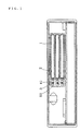
Fig. 1 is a front view showing one embodiment of the
present invention from which a front panel is removed;
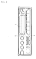
Fig. 2 is a front view showing one embodiment of the
present invention;
Fig. 3 is a bottom view showing main parts in one
embodiment of the present invention;
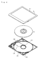
Fig. 4 is an exploded perspective view showing an
optical disk cassette which is applied to one embodiment of
the present invention;
Fig. 5 is a bottom view showing a tray according to one
embodiment of the present invention;
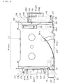
Fig. 6 is a side view showing a disk containing portion
according to one embodiment of the present invention;
Fig. 7 is a cross sectional view showing a height
detecting device for a disk receiving frame according to one
embodiment of the present invention;
Fig. 8 is an exploded view showing the height detecting
device for a disk receiving frame according to one
embodiment of the present invention;
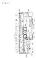
Fig. 9 is a side view showing a loading device
according to one embodiment of the present invention;
Fig. 10 is a plan view showing the loading device
according to one embodiment of the present invention;
Fig. 11 is a side view showing main parts in one
embodiment of the present invention;
Fig. 12 is a plan view showing a tray according to
another embodiment of the present invention;
Fig. 13 is a side view showing a containing portion
according to another embodiment of the present invention;
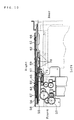
Fig. 14 is a side view showing a loading and unloading
equipment according to another embodiment of the present
invention;
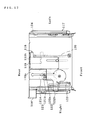
Fig. 15 is a plan view showing the loading and
unloading equipment and a second elevator device according
to another embodiment of the present invention; and
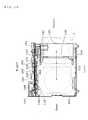
Fig. 16 is a side view showing the second elevator
device according to another embodiment of the present
invention.
DESCRIPTION OF THE PREFERRED EMBODIMENTS
A multi-disk player according to one embodiment of the
present invention shown in Fig. 1 is combined with an AM/FM
radio receiver and a CD player carried by an automobile.
Three slit-shaped insertion ports 2 are formed on the
front surface of the multi-disk player so as to load three
optical disk cassettes 1, and an ejection key 3 used for an
ejecting operation is provided at the left side of each of
the insertion ports 2.
As shown in Fig. 2, a front panel 4 is provided on the
front surface of the multi-disk player. If the front panel
4 is shaken downward to the front, the front surface of the
multi-disk player is opened. Consequently, the three
insertion ports 2 and the three ejection keys 3 are exposed,
thereby to make it possible to insert, discharge and replace
the optical disk cassettes 1.
Keys such as various control keys of the multi-disk
player and the FM/AM radio, a CD player and the like, a
locking releasing key of a locking device for locking the
front panel 4 in its closed position are provided on the
front surface of the front panel 4.
As shown in Fig. 3, the multi-disk player comprises a
containing portion 5 which can contain the three optical
disk cassettes 1, a record playing equipment 6 disposed
behind the containing portion 6, and a disk loader 7 for
loading one optical disk cassette 1 selected out of the
three optical disk cassettes 1 into the record playing
equipment 6 from the containing portion 5 and returning the
optical disk cassette 1 loaded in the record playing
equipment 6 to its original position in the containing
portion 5.
As shown in Fig. 4, the above described optical disk
cassette 1 is so adapted that an optical disk 8 having a
diameter of 64 mm is rotatably inserted into a cassette case
11 comprising an upper shell 9 and a lower shell 10 each
having a flat surface measuring approximately 72 mm x 68 mm.
A spindle hole 12 is formed in the center of the lower shell
10, and a spindle 13 (shown in Fig. 3) of the record playing
equipment 6 is caused to enter the spindle hole 12 to rotate
the optical disk 8. A window 14 is provided in one side
part of the lower shell 10, and records on a recording
surface of the optical disk 8 are read by an optical head 15
(shown in Fig. 3), which looks in the window 14, of the
record playing equipment 6. The above described window 14
is opened or closed by a shutter 16 slidably supported on
the lower shell 10.
As shown in Fig. 3, the optical disk cassettes 1 are
inserted one at a time into respective trays 17 made of a
metal plate when they are respectively inserted into the
containing portion 5 through the insertion ports 2. As
shown in Fig. 5, the tray 17 has a clip 18 made of a plate
spring entering in a V shape the lower part of its left rear
edge, and a recess 19 to and from which the clip 18 is
fitted and extracted is formed in a left rear edge of the
lower shell 10. If the optical disk cassette 1 is inserted
into the tray 17 to a predetermined depth, therefore, the
clip 18 is fitted in the recess 19 of the lower shell 10.
Accordingly, the optical disk cassette 1 is positioned in
the tray 17 and held therein.
The shutter 16 of the optical disk cassette 1 is pushed
open by a projection 20 formed by folding a part of the
right sidewall of the tray 17 inward when the optical disk
cassette 1 is inserted into the containing portion 5.
This multi-disk player comprises an ejecting device 21
for detaching, when any one of the ejection keys 3 is
depressed, the clip 18 of the tray 17 corresponding to the
ejection key 3 from the recess 19 of the lower shell 10 and
ejecting the optical disk cassette 1 in the tray 17 forward.
This ejecting device 21 comprises the above described
ejection keys 3, a slide plate 22 supported on the left
sidewall of each of the trays 17 so as to be movable back
and forth, a return spring 23 for urging the slide plate 22
forward, an ejection spring 24, and a slide plate 59 of the
disk loader 7 (shown in Fig. 9).
If the ejection key 3 is operated, the slide plate 59
is moved to the height of the tray 17 corresponding to the
ejection key 3, and is moved forward after an engaging
portion 31 of the tray 17 is positioned between a pair of
engaging members 71, to push the engaging portion 31
forward. At this time, an end 22a of the slide plate 22 is
caught by a projection 27a provided in a guide member 27,
whereby a rear end of the slide plate 22 pushes the clip 18.
Consequently, the clip 18 is pushed out leftward, to be
detached from the recess 19 of the optical disk cassette 1.
The above described ejection spring 24 comprises a
plate spring formed to connect with the above described clip
18 and is so constructed that its one end is supported on
the left rear of the tray 17 and the other end, that is, a
free end 24a advances to the center of the tray 17 in a natural
state. If the optical disk cassette 1 is loaded into the
tray 17, the rear surface of the optical disk cassette 1
pushes the free end 24a of the ejection spring 24 into a right
rear end of the tray 17. Thereafter, if the ejection key 3
is depressed to detach the clip 18 from the recess 19 of the
optical disk cassette 1, the optical disk cassette 1 is
ejected forward by an elastic restoring force of the
ejection spring 24. Consequently, the front thereof is
exposed from the insertion port 2, thereby to make it
possible to pull the optical disk cassette 1 out by hand.
An engaging portion 31 extending toward the left of the
guide member 27 is located in the left rear of each of the
trays 17. A left end of the engaging portion 31 is further
folded downward, as shown in Fig. 6, thereby to provide an
engaging portion 31a. An inverted V-shaped positioning
groove 32 is formed in a lower edge of the engaging portion
31a.
Three levers 33 corresponding to the respective trays
17 are supported shakably in a seesaw shape on the left side
surface of the guide member 27 on the left, and a
positioning pin 34 is projected leftward from a rear end of
each of the levers 33. The positioning pin 34 and the lever
33 are urged in a clockwise direction until a front end of
the lever 33 is caught by a stopper 36 projected on the left
side surface of the guide member 27 by a pressure bar spring
35 supported on the guide member 27. The positioning pin 34
is fitted in the positioning groove 32 of the tray 17,
whereby the tray 17 is put in a predetermined position of
the containing portion 5.
The slide plate 59 is returned to a first predetermined
forward position where a pair of engaging members 71 is
positioned on both sides of the engaging portion 31 of the
tray 17 which is put in a predetermined position, to wait
until any one of the ejection keys 3 is operated in a
position corresponding to the height of any one of the
optical disk cassette 1. If any one of the ejection keys 3
is operated, the slide plate 59 starts to be moved forward
after being moved to the height of the optical disk cassette
1 corresponding to the ejection key 3. For example, if the
slide plate 59 is moved to a predetermined forward position
where the rear engaging member 71 catches the engaging
portion 31 of the tray 17, a proximity switch 80 shown in
Fig. 11 is turned on.
The proximity switch 80 is turned on and then, is
turned off by further forward movement of the slide plate
59. If the slide plate 59 is moved forward by further
driving a motor continuously for, for example, one second on
the basis of the termination of the on state, the
positioning pin 34 is driven downward by the taper of the
positioning groove 32, whereby the lever 33 is rotated in a
counterclockwise direction. Accordingly, the tray 17 can be
moved forward by a predetermined amount from a predetermined
position. The optical disk cassette 1 is ejected in the
above described manner while the tray 17 is moved forward by
a predetermined amount from a predetermined position.
The slide plate 59 is moved forward at the time of
ejection by driving the motor for, for example, one second
on the basis of the termination of the on state of the
proximity switch 80 as described above, and is returned to
the position where the proximity switch 80 is turned on
again after the time has elapsed. The tray 17 is also
returned to a predetermined position as the slide plate 59
is returned. The slide plate 22 is returned to its original
position by the return spring 23 at this time, whereby the
clip 18 is returned to the position where it enters the tray
17.
Respective pairs of front and rear pins 25 and 26 are
projected on both left and right sides of each of the trays
17. The pins 25 and 26 are respectively inserted into the
guide grooves 29 and 30 formed in the guide members 27 and
28 provided on both left and right sides of the tray 17
movably back and forth.
As described in the foregoing, the tray 17 is
positioned by fitting the positioning pin 34 in the
positioning groove 32 of the engaging portion 31. The
positioning groove 32 of the engaging portion 31 is so
formed that the tray 17 is not moved backward even if the
optical disk cassette 1 is forced into the tray 17 and the
slide plate 59 is driven backward in a state where the tray
17 is positioned. Therefore, a pin which is engaged with a
projection 33a of the lever 33 is formed in the slide plate
59. The lever 33 is first rotated to disengage the
positioning pin 34 and the engaging portion 31 by the
movement of the slide plate 59 and then, the tray 17 is
moved by the engaging member 71.
As shown in Fig. 5, the containing portion 5 is
provided with a cassette detecting device 37 so as to
determine whether the optical disk cassette 1 is loaded into
each of the trays 17 which is put in a predetermined
position in the containing portion 5.
The cassette detecting device 37 comprises a detecting
plate 38 supported on the right rear of each of the trays 17
movably back and forth, a return spring 39 for urging the
detecting plate 38 forward, and a microswitch 40 which is
supported on the right side of the guide member 28 on the
right and is turned on or off by the advance or retreat of
the detecting plate 38. If the optical disk cassette 1 is
loaded into the tray 17, an end 38d of the detecting plate
38 is pushed backward by the optical disk cassette 1 against
the return spring 39. If the microswitch 40 is turned off,
therefore, the loading of the optical disk cassette 1 is
detected.
The results of the detection are indicated by lighting
one or both of a green loading indicator lamp 41 (shown in
Fig. 1), for example, contained in the ejection key 3
corresponding to the tray 17, for example, or a loading
indicator lamp provided on the front panel 4. If the
optical disk cassette 1 is not loaded, the results are not
reasonably indicated by lighting.
The above described record playing equipment 6
comprises a main body 43 supported on a chassis 42 common to
the record playing equipment 6 and the containing portion 5,
and a disk receiving frame 45 supported on the main body 43
movably up and down through a pair of right and left
pantograph mechanisms 44.
As shown in Fig. 3, the above described main body 43
comprises a sub-chassis 46, a spindle motor 47 fixed to the
sub-chassis 46, a spindle 48 fixed to an output shaft of the
spindle motor 47, an optical head 15 supported on the sub-chassis
46 movably rightward and leftward, a head driving
device 49 for driving the optical head 15, and a disk
up-and-down driving device 50 (see Fig. 6) for driving the
disk receiving frame 45 up and down.
The disk receiving frame 45 is provided with a pair of
right and left guide rails 51 disposed with proper spacing
in the lateral direction, and guide grooves into and from
which the pairs of front and rear pins 25 and 26 projected
on both left and right sides of the tray 17 as shown in Fig.
3 are respectively inserted and extracted from the front are
respectively formed in the guide rails 51.
When the optical disk cassette 1 is transferred between
the record playing equipment 6 and the containing portion 5,
the disk up-and-down driving device 50 is operated to make
the heights of the guide grooves of the disk receiving frame
45 equal to the heights of the guide grooves 29 and 30 of
the tray 17 for holding the selected optical disk cassette 1
in the containing portion 5.
The height of the disk receiving frame 45 is detected
by a detecting device 52 provided throughout from the sub-chassis
46 to the disk receiving frame 45. The detecting
device 52 comprises a plate spring 53 having its one end
fixed to the disk receiving frame 45 and its other end
slidably held on the lower surface of the chassis 46, and a
pair of electrodes 54 supported by the sub-chassis 46 so as
to be slidably brought into contact with both edges of the
plate spring 53, as shown in Figs. 7 and 8. Slit 55
corresponding to a plurality of predetermined heights of the
disk receiving frame 45 are formed in the above described
plate spring 53.
In the detecting device 52, if the disk receiving frame
45 is raised and lowered, the middle part and the other end
of the plate spring 53 move back and forth along the lower
surface of the sub-chassis 46. If the slit 55 is put in the
position of either one of the electrodes 54, both the
electrodes 54 are insulated from each other, so that
detection signals each composed of an OFF signal are
outputted.
When the detection signals are outputted, therefore, it
is judged which of the trays 17 has a height corresponding
to a height at which the disk receiving frame 45 is
positioned on the basis of the position where the disk up-and-down
driving device 50 is started, the direction in
which the disk up-and-down driving device 50 is driven, and
the number of detection signals after starting the disk up-and-down
driving device 50. The disk up-and-down driving
device 50 is stopped at a height corresponding to the height
of the selected tray 17, thereby to make the heights of the
guide grooves of the disk receiving frame 45 equal to the
heights of the guide grooves 29 and 30 of the tray 17
holding the selected optical disk cassette 1 in the
containing portion 5.
The disk receiving frame 45 is provided with a
positioning spring which is engaged with the pin 25 of the
tray 17 for positioning the tray 17 itself.
As shown in Figs. 9 and 10, the above described disk
loader 7 comprises an elevator 56, an up-and-down driving
device 57, an up-and-down plate 58, a slide plate 59, and a
back-and-forth driving device 60. The back-and-forth
driving device 60 is of epicyclic gear construction. A
pinion gear 69 and a gear of a motor are always connected to
each other even if the up-and-down plate 58 is raised and
lowered.
The above described elevator 56 is supported on the
left of a right sidewall 61 of the chassis 42 through a pair
of pins 62 movably back and forth, and is driven back and
forth by the up-and-down driving device 57.
A cam groove 63 comprising three horizontal grooves
having heights corresponding to the heights of the
respective trays 17 and disposed in the order of height with
predetermined spacing in the longitudinal direction and an
inclined groove for causing the horizontal grooves to
connect with each other in the order of height is formed in
the above described up-and-down plate 58. In addition, an
arc-shaped groove 65 extending upward and downward is formed
on the right sidewall 61 of the chassis 42, and a pair of
pins 64 corresponding to the cam groove 63 and the arc-shaped
groove 65 is projected on the right side surface of
the slide plate 59. The pins 64 are respectively inserted
through the cam groove 63 and the arc-shaped groove 65. If
the up-and-down plate 58 is moved back and forth, therefore,
the slide plate 59 supported on the up-and-down plate 58
through the pins 64 is guided by the arc-shaped groove 65 to
be raised and lowered.
A pair of upper and lower guide grooves 66 extending
backward and forward is formed in the above described
up-and-down plate 58, and a pair of pins 67 projected from
the right surface of the slide plate 59 is slidably inserted
into the guide grooves 66, respectively, whereby the slide
plate 59 is supported on the up-and down plate 58 movably
back and forth.
A rack 68 is formed throughout the entire length of a
lower edge the slide plate 59, and two pinion gears 69 which
are engaged with the rack 68 and three gears 70 which
interlock both the pinion gears 69 in the same direction are
rotatably supported on the up-and-down plate 58.
The plurality of pinion gears 69 and the rack 68 are
thus engaged with each other, thereby to make it possible to
increase the length of the stroke of the slide plate 59 to
the length which is the sum of the length of the stroke and
the spacing between the plurality of pinion gears 69. In
other words, the length of the slide plate 59 is decreased
by the spacing between the plurality of pinion gears 69,
thereby to make it possible to miniaturize the multi-disk
player as a whole.
The engaging members 71 projected leftward are
projected properly spaced in the longitudinal direction in a
rear end of the above described slide plate 59. When the
slide plate 59 is put in a predetermined position in the
vicinity of a front end of the stroke of the slide plate 59,
the engaging portion 31 of each of the trays 17 is
positioned between the engaging members 71 as viewed from
the top.
Specifically, as shown in Fig. 9, a positioning pin 72
projected rightward is provided in a front end of the slide
plate 59, and the positioning pin 72 is fitted in a
positioning groove 74 of a positioning tool 73 supported on
a front end of the up-and-down plate 58, thereby to put the
slide plate 59 in a predetermined position.
As shown in Fig. 11, the position of the positioning
tool 73 is held fixed by inserting a pin 76 of the
positioning tool 73 through a longitudinal groove 75 formed
at the front of the right sidewall 61 of the chassis 42
movably upward and downward.
As shown in Fig. 11, a loading detecting device 77 for
determining whether or not the slide plate 59 is in this
predetermined position is provided on the right sidewall 61
of the chassis 42.
The loading detecting device 77 comprises a detecting
plate 78 supported on the right sidewall 61 of the chassis
42 movably back and forth, a return spring 79 for urging the
detecting plate 78 backward, and the proximity switch 80
which is switched between its on and off states by the
advance or retreat of the above described detecting plate
78.
The proximity switch 80 is turned off when the above
described detecting plate 78 catches the front end of the
slide plate 59 to move forward, as shown in Fig. 9, thereby
to determine that the slide plate 59 and the tray 17 are put
in predetermined wait positions.
If the tray 17 is moved from the containing portion 5
to the record playing portion 6, the above described
determination is made by a moving member 28f facing the
guide groove 30 from a hole 28e of the guide member 28 and a
switch 28g, as shown in Fig. 5. Specifically, when the tray
17 is in the containing portion 5, the moving member 28f is
moved forward against a spring by the pin 26, whereby the
switch 28g is turned off. If the tray 17 is moved backward,
the moving member 28f is moved by the spring, whereby the
switch 28g is turned on. Consequently, a red loading
indicator lamp 81, for example, contained in the ejection
key 3 corresponding to the tray 17 which is moved to the
record playing portion 6 is lighted, to take care not to
erroneously insert the optical disk cassette 1 into the
insertion port 2 having no tray 17.
Furthermore, as shown in Fig. 11, a height detecting
device 82 is provided on the right sidewall 61 of the
chassis 42 so as to determine which of the trays 17 is moved
from the containing portion to the record playing portion 6.
The height detecting device 82 comprises a detecting
plate 83 fixed to the left side surface of the elevator 56,
driving members 84 provided properly spaced in the
longitudinal direction above and below the detecting plate
83, and two proximity switches 85 which are turned on by the
movement of the driving members 84 to the opposed positions.
The upper proximity switch 85 is turned on when the elevator
56 retreats so that the up-and-down plate 58 and the slide
plate 59 are at heights corresponding to the upper tray 17,
the lower proximity switch 85 is turned on when the elevator
56 advances so that the up-and-down plate 58 and the slide
plate 59 are at heights corresponding to the lower tray 17,
and both the proximity switches 85 are turned on when the
up-and-down plate 58 and the slide plate 59 are at heights
corresponding to the intermediate tray 17. When the upper
proximity switch 85 is turned on, it is determined by a
counter value whether the height of the intermediate tray 17
is the height of the lower tray 17.
In this multi-disk player, a control circuit (not
shown) composed of a microcomputer controls the motor, the
indicator lamp and the like on the basis of each of the
above described keys and switches, to obtain a desired
operation. If the optical disk cassette 1 is inserted
through the insertion port 2 and is held in the tray 17, the
green indicator lamp 41 of the ejection key 3 corresponding
to the tray 17 lights up. At this time, if the optical disk
cassette 1 is also loaded into the other tray 17, the green
indicator lamp 41 of the ejection key 3 corresponding to the
tray 17 reasonably lights up. Thereafter, if the front
panel 4 is closed to depress a multi-disk operating key
provided on the front surface thereof, the slide plate 59 is
raised and lowered to a height at which the engaging portion
31 of the tray 17 selected in accordance with a
predetermined order or selected by a selection key provided
on the front surface of the front panel 4 is positioned
between the engaging members 71 of the slide plate 59 of the
disk loader 7 and at the same time, the disk receiving frame
45 of the record playing portion 6 is raised and lowered to
a height corresponding to the tray 17.
After the slide plate 59 and the disk receiving frame
45 are moved to heights corresponding to the selected tray
17, the slide plate 59 is moved backward, to put the tray 17
on the guide rail 51 of the disk receiving frame 45 from the
guide members 27 and 28 of the containing portion 5.
At this time, a switch 28g provided to correspond to
the tray 17 is turned on, so that the green indicator lamp
41 corresponding to the tray 17 goes out and a read loading
indicator lamp 81 lights up.
Thereafter, the disk receiving frame 45 is lowered, and
the spindle 48 is caused to enter the spindle hole 12 of the
optical disk cassette 1 to be pressed against the center of
the optical disk 8 to such a degree that it can be
frictionally transmitted and then, the spindle motor 47 is
started. Consequently, the reading of records by the
optical head 49 is started. The slide plate 59 is returned
to the containing portion 5, to prepare for an ejecting
operation.
When the playing of the records is terminated, the
slide plate 59 is moved from the containing portion 5 to the
record playing equipment 6 and then, one end of an end 59a
of the slide plate 59 abuts against a switch 59b, whereby
the switch 59b is turned on. If it is thus determined that
the slide plate 59 is moved to a predetermined position on
the side of the record playing equipment 6, the containing
portion 5 and the disk up-and-down driving device 50 are
operated in the reverse direction to raise the disk
receiving frame 45 to its original height, and the slide
plate 59 of the disk loader 7 is moved forward to move the
tray 17 from the disk receiving frame 39 to the containing
portion 5, whereby the tray 17 is supported by the original
guide members 27 and 28.
At this time, the switch 28g is turned off, so that the
red loading indicator lamp 81 corresponding to the tray 17
goes out. Since the optical disk cassette 1 in the tray 17
is not in an ejected state, the microswitch 40 remains off,
so that the green indicator lamp 41 corresponding to the
tray 17 lights up.
If the ejection key 3 of any one of the optical disk
cassettes 1 remaining in the containing portion 5 is
depressed while records on the selected optical disk
cassette 1 are being played, the optical disk cassette 1 is
moving back and forth from and to the record playing
equipment 6, or when all the optical disk cassettes 1 are
contained in the containing portion 5, the clip 18 provided
in the tray 17 is detached from the recess 19 of the optical
disk cassette 1. Consequently, the ejection spring 24 is
elastically restored, whereby the optical disk cassette 1 is
pushed out forward and the front thereof is projected
forward from the insertion port 2. At this time, the
microswitch 40 is turned on. Accordingly, the green
indicator lamp 41 corresponding to the tray 17 goes out even
while records are being played. The optical disk cassette 1
whose front is projected from the insertion port 2 may be
pushed into the insertion port 2 again, or may be extracted
from the insertion port 2 to insert another optical disk
cassette 1 into the insertion port 2. When the optical disk
cassette 1 is inserted, the microswitch 40 is reasonably
turned off. Accordingly, the green indicator lamp 41
corresponding to the tray 17 lights up.
Furthermore, it can be easily understood that two or
more optical disk cassettes 1 remaining in the containing
portion 5 can be simultaneously ejected by simultaneously
depressing two or more ejection keys 3.
According to the multi-disk player, therefore, the
optical disk cassette 1 remaining in the containing portion
5 while records are being played can be taken out and
replaced, and another optical disk cassette 1 can be added.
Consequently, the multi-disk player becomes more convenient
for use.
In an ejecting device 118 according to another
embodiment of the present invention shown in Fig. 12, an
ejection plate 119 catching a front end of an optical disk
cassette 1 is supported slidably back and forth on a tray
117. The ejection plate 119 has a horizontal plate 119a
along the upper surface of the tray 117 and a vertical plate
119b extending downward from a rear end of the horizontal
plate 119a and catching a rear end of the optical disk
cassette 1.
Furthermore, bias means 120 composed of a helical
tension spring is stretched between the horizontal plate
119a and the tray 117. Further, a latch slit 121 comprising
a longitudinal slit 121a extending backward and forward and
a transverse slit 121b continuously extended leftward from a
front end of the longitudinal slit 121a is formed on the
above described horizontal plate 119a. In addition, the
ejecting device 118 is provided with a latch lever 122
having a pin 122a entering the latch slit 121 and a lever
122b projected toward the right of the tray 117 and
supported on the tray 117 so as to be horizontally rotated
around a position which is off-centered from the pin 122a
and second bias means 123 composed of a helical tension
spring for urging the latch lever 122 in the direction in
which the pin 122a enters the transverse slit 121b.
If the optical disk cassette 1 is pushed into the tray
117, the ejection plate 119 is pushed backward. If the
ejection plate 119 is pushed into the position of the
transverse slit 121b with the pin 122a being in the
longitudinal slit 121a, the second bias means 123 moves the
pin 122a into the transverse slit 121b. Consequently, the
ejection plate 119 is held in its set position, whereby the
optical disk cassette 1 is held in a predetermined position
of the tray 117 by a positioning spring 124.
Furthermore, in the ejecting device 118 according to
the present embodiment, sliding members 126 respectively
corresponding to the trays 117 are provided in the
containing portion 125, as shown in Fig. 13. If an
arbitrary ejection key is pushed by not less than a
predetermined amount, the sliding member 126 which retreats
in synchronism with the ejection key pushes the lever 122b
of the tray 117 corresponding to the ejection key backward
against the second bias means 123, thereby to move the pin
122a from the transverse slit 121b to the longitudinal slit
121a. If the pin 122a is moved to the longitudinal slit
121b, the engagement between the pin 122a and the transverse
slit 121b is nullified. Consequently, the ejection plate
119 is drawn forward vigorously by the bias means 120,
whereby the optical disk cassette 1 is ejected from the tray
117.
In this tray 117, the ejection plate 119 is held in a
predetermined position by the latch lever 122 even when the
positioning function of the positioning spring 124 is lost
by some reason, thereby to eliminate the possibility that
the optical disk cassette 1 is ejected against its will.
Accordingly, the optical disk cassette 1 can be ejected only
when the ejection key 3 is arbitrarily operated.
The containing portion 125 according to the present
embodiment is provided with gates 127 which are swingably
raised and lowered ahead of the respective trays 117. Each
of the gates 127 is urged downward by a spring (not shown).
When the tray 117 is positioned in the containing portion
125, the gate 127 is pushed open upward to the front from
the inside by a front end of the tray 117. Consequently,
the optical disk cassette 1 can be freely inserted into an
empty tray 117 from the front, or can be freely taken out
from the tray 117.
If the tray 117 in which the optical disk cassette 1 is
set is pulled out backward by not less than a predetermined
amount from the containing portion 125, whereby the optical
disk cassette 1 is moved toward the back of the front end of
the containing portion 125, the above described gate 127 is
shaken downward to the rear from the upper front by a spring
by being deprived of its support, to close the front of the
tray 117. Consequently, another optical disk cassette 1 can
be reliably prevented from being erroneously inserted into a
space to be ensured in the containing portion 125 for the
optical disk cassette 1 in which records are being played or
which is moving back and forth from and to the record
playing equipment and the tray 117.
Furthermore, as shown in Figs. 14 and 15, an elevator
device 130 according to the present embodiment comprises a
pair of right and left cam plates 131 to 132, one up-and-down
plate 133, one sliding member 134, and a synchronizing
device 134 for mechanically interlocking both the cam plates
131 and 132.
As shown in Figs. 14 and 16, both the cam plates 131
and 132 are respectively supported on a chassis 135 slidably
back and forth, and racks 136 and 137 are formed in upper
front edges of the cam plates 131 and 132.
Furthermore, as shown in Fig. 14, two rows of cam
grooves 138 each having three horizontal grooves 138a having
heights corresponding to the heights of the respective trays
and disposed properly spaced in the longitudinal direction
in the order of height and an inclined groove 138b for
causing the respective grooves 138a to connect with each
other in the order of height are formed properly spaced in
the longitudinal direction in the cam plate 131 on the right
out of the two cam plates. An extending inclined groove
138c extending from an end of the lowermost horizontal
groove 138a to an arbitrary height larger than that of the
other higher horizontal groove 138a on the opposite side to
the other higher horizontal groove 138a and an extending
horizontal groove 138d connecting with an upper end of the
inclined groove 138c are formed in each of the cam grooves
138.
Two rows of guide grooves 139 composed of long holes
are formed with the same spacing in the longitudinal
direction as that between the cam grooves 138 on the right
sidewall of the chassis 135, and two pins 140 projected on
the outer side surface of the up-and-down plate 133 disposed
inside of the above described cam plate 131 are inserted
into the corresponding cam grooves 138 and guide grooves
139. A pinion 143 which is interlocked with an elevator
motor 141 through an interlocking gear device 142 is engaged
with the rack of the cam plate 131 to rotate the elevator
motor 141 in the forward direction or the reverse direction.
Consequently, the cam plate 131 is moved back and forth and
is driven by the cam groove 138 and the pins 140 are guided
by the guide grooves 139, whereby the up-and-down plate 133
is moved up and down.
The cam groove 138 is provided with the extending
horizontal groove 138c and the extending horizontal groove
138d, whereby the up-and-down plate 133 and the sliding
member 134 supported thereon can be held in a position above
a main body 157 of a record playing equipment 153 shown in
Fig. 16 at a height corresponding to the extending
horizontal groove 138 while the optical disk cassette 1 is
loaded into the record playing equipment 153, for example,
in addition to a height corresponding to each of the trays
117.
The sliding member 134 is supported on the above
described up-and-down plate 133 movably back and forth, and
a sliding driving device 144 for driving the sliding member
134 is supported thereon. Another rack 145 is formed in a
lower edge of the above described sliding member 134. The
above described sliding driving device 144 is so constructed
as to transmit the rotation of the slide motor 146 to one of
two pinion gears 149 which are engaged with this rack 145
through a transmission gear device 148 and further transmit
the rotation of the one pinion gear 149 to the other pinion
gear 149 by a timing belt 150 to drive the sliding member
134, as shown in Fig. 15.
Different cam grooves 151 are respectively formed in
both the above described cam plates 131 and 132. The cam
grooves 151 are the same as the two rows of cam grooves 138
formed in the above described cam plate 131 on the right in
that each of them has three horizontal grooves 151a
respectively having heights corresponding to the heights of
the trays and disposed properly spaced in the longitudinal
direction in the order of height and an inclined groove 151b
for causing the respective horizontal grooves 151a to
connect with each other in the order of height. However,
the cam grooves 151 differ from the cam grooves 138 in that
each of them has a floating groove 151d having an extending
inclined surface 151c extending from an end of the lowermost
horizontal groove 151a to a predetermined height smaller
than that of the other higher horizontal groove 151a on the
opposite side to the other higher horizontal groove 151a (at
the back thereof in this case).
Furthermore, each of the guide grooves 152 formed on
both right and left sidewalls of the chassis 135 to
correspond to the cam grooves 151 comprises a long hole 152a
extending downward in a horn shape and a circular hole 152b
connecting with a lower end of the long hole 152a and having
a larger diameter than that of the lower end.
A pin 155 projected both rightward and leftward from a
disk receiving frame 154 of the record playing equipment 153
is inserted through the cam groove 151 and the guide groove
152, as shown in Fig. 16. The disk receiving frame 154 is
supported movably back and forth on the main body 157 of the
record playing equipment 153 through a pantograph mechanism
156, and is urged toward the main body 157 by a spring (not
shown). Although the main body 157 may be fixed to the
chassis 135, the main body 157 is supported on the chassis
135 through a vibration control device. In addition, the
movement in one of right and left directions of the
pantograph mechanism 156 is regulated by a right end wall of
the main body 157 provided with a guide groove 166. A
spring is engaged with a groove formed in a top end of a pin
167 inserted through the guide groove 166, thereby to urge
the pantograph mechanism 156 as well as regulate the
movement in the other direction of the pantograph mechanism
156. Further, the cam plate 132 on the left is urged
backward by a helical tension spring 168 stretched between
the cam plate 132 on the left and a rear end of the chassis
135.
As shown in Fig. 14, a pinion 159 which is engaged with
the rack 137 of the cam plate 132 on the left is connected
to the pinion 143 for driving the cam plate 131 on the right
by a synchronizing mechanism composed of an interlocking
shaft 158. Consequently, the two cam plates 131 and 132 are
synchronously moved back and forth, thereby to make it
possible to put the disk receiving frame 154 to a height
corresponding to the height of each of the trays and a
position closer to the main body 157 than the height.
If the cam plates 131 and 132 are further moved from
the positions of the cam plates 131 and 132 in which the pin
155 is positioned in the lowermost horizontal groove 151a
toward the other higher horizontal groove 151a, that is,
forward, the pin 155 urged by a spring force is guided by
the extending inclined surface 151c to be moved toward the
main body 157. The optical disk supported on the disk
receiving frame 154 is pressed against the spindle of the
main body 157 as the pin 155 is moved.
Specifically, the elevator motor 141 used for raising
and lowering the up-and-down plate 133 is also used for
raising and lowering the disk receiving frame 154 without
using a motor used for raising and lowering the disk
receiving frame 154 to reduce the number of motors by one,
resulting in reduced total cost.
One photointerrupter 160 is fixed to the upper part of
the right sidewall of the chassis 135, and three tongue
members 161, 162 and 163 which cross the photointerrupter
160 as the photointerrupter 160 is moved are projected
outward to the right with predetermined spacing in the
longitudinal direction on the upper part of the cam plate
131 on the right.
It is assumed that in the initial state, the up-and-down
plate 133, the sliding member 134 and the disk
receiving frame 154 are at heights corresponding to the tray
117 in the upper stage. In this case, the cam plate 131 is
positioned in a rear stroke end in the initial state, so
that the front tongue member 163 interrupts a light path
between light emitting means and light receiving means of
the photointerrupter 160.
If the optical disk cassette 1 in the upper stage is
selected, the elevator motor 141 is not started, whereby the
sliding member 134 can be moved from a front stroke end to
the rear stroke end by rotating the slide motor 146 in the
forward direction. An engaging portion 164 of the tray 117
in the upper stage (shown in Fig. 12) is positioned between
a pair of front and rear engaging portions 165 of the
sliding member 134. The tray 117 in the upper stage and the
optical disk cassette 1 are loaded into the disk receiving
frame 154 from the containing portion 125 by moving the
sliding member 134 to the rear stroke end.
If the optical disk cassette 1 in the middle stage or
the lower stage is selected, the elevator motor 141 is
started in the forward direction, whereby the cam plates 131
and 132 are moved forward. The front tongue member 163
passes through the photointerrupter 160 to open the light
path of the photointerrupter 160 while the cam plates 131
and 132 are moving forward and then, the middle tongue
member 162 interrupts the light path of the photointerrupter
160, thereby to determine that the sliding member 134 and
the disk receiving frame 154 are at heights corresponding to
the intermediate tray 117.
If the tray 117 in the middle stage is selected, the
elevator motor 141 is stopped when the middle tongue member
162 is detected, whereby the tray 117 in the middle stage
and the optical disk cassette 1 are loaded into the disk
receiving frame 154 from the containing portion 125.
If the tray 117 in the lower stage is selected, the
front tongue member 163 passes through the photointerrupter
160 to open the light path of the photointerrupter 160 and
then, the middle tongue member 162 and the rear tongue
member 161 interrupt the light path of the photointerrupter
160 twice, thereby to determine that the up-and-down plate
133, the sliding member 134 and the disk receiving frame 154
are at heights corresponding to the tray 117 in the middle
stage and at the same time, the elevator motor 141 is
stopped, whereby the tray 117 in the lower stage and the
optical disk cassette 1 are loaded into the disk receiving
frame 154 from the containing portion 125.
After the tray 117 in any stage and the optical disk
cassette 1 are loaded into the disk receiving frame 154, the
elevator motor 141 is rotated in the forward direction,
thereby to move the cam plates 131 and 132 to the front
stroke end. Consequently, the disk receiving frame 154 is
moved toward the main body 157, thereby to start to play
records.
The main body 157 is provided with a limit switch (not
shown) which is operated in the stroke end of the cam plate
131. If the limit switch is turned on or off, the elevator
motor 141 is stopped. In this state, a state where records
can be played is detected.
If the ejection key corresponding to the optical disk
cassette 1 in which records are being played is depressed
once, the playing of the records is interrupted, so that the
elevator motor 141 is rotated in the reverse direction.
Consequently, the up-and-down plate 133, the sliding member
134 and the disk receiving frame 154 are returned to heights
corresponding to the optical disk cassette 1. Thereafter,
the slide motor 136 is rotated in the reverse direction, so
that the sliding member 134 moves forward. Consequently,
the tray 117 and the optical disk cassette 1 are returned to
the containing portion 125 from the disk receiving frame
154. If the same ejection key is depressed once again after
the tray 117 and the optical disk cassette 1 are returned to
the containing portion 125, the optical disk cassette 1 is
ejected from the tray 117.
Although in the present embodiment, the
photointerrupter 160 is used, it can be determined that the
up-and-down plate 133, the sliding member 134 and the disk
receiving frame 154 are put in positions corresponding to
the height of any one of the optical disk cassettes 1 by
only providing one of sensors such as proximity switches,
microswitches and photosensors if the cam plate 131 or 132
is thus provided with portions to be detected such as tongue
members 117, projections, recesses, slits and magnetic
members whose number is the same as the number of stages of
the trays 117 properly spaced in the direction in which the
cam plate 131 or 132 advances or retreats. The number of
sensors in a detecting device for detecting the heights of
the up-and-down plate 133, the sliding member 134 and the
disk receiving frame 154 is thus decreased to one, thereby
to make it possible to simplify the construction as well as
reduce the entire cost.
In the above described embodiment, it is determined by
switching the microswitch 166 fixed to the front of the up-and-down
plate 133 to an on or off state by the sliding
member 134 that the sliding member 134 is positioned in the
front stroke end, and it is determined by pressing the plate
spring 168 for switching the microswitch 167 fixed to the
rear of the up-and-down plate 133 to an on or off state
backward by the sliding member 134 to turn the microswitch
167 off or on that the sliding member 134 is positioned in
the rear stroke end.
It goes without saying that the sliding member 134 may
be provided with two portions to be detected such as tongue
members, projections, recesses, slits and magnetic members
are provided properly spaced in the longitudinal direction
so that one sensor supported on the up-and-down plate 133
senses which of the stroke ends is a stroke end in which the
sliding member 134 is positioned, thereby to make it
possible to further reduce the entire cost.
Although the present invention has been described and
illustrated in detail, it is clearly understood that the
same is by way of illustration and example only and is not
to be taken by way of limitation.